APM3095P中文资料
液晶8脚贴片元器件参数大集合
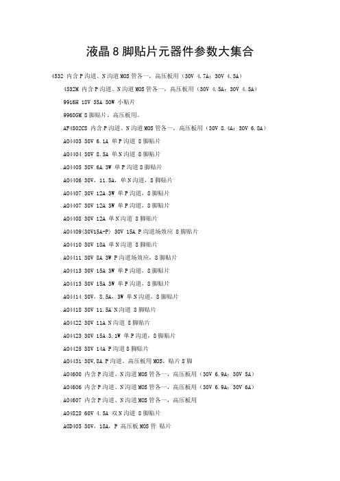
液晶8脚贴片元器件参数大集合4532 内含P沟道、N沟道MOS管各一,高压板用(30V 4.7A;30V 4.5A)4532M 内含P沟道、N沟道MOS管各一,高压板用(30V 4.5A;30V 4.5A)9916H 18V 35A 50W 小贴片9960GM 8脚贴片,高压板用。
AF4502CS 内含P沟道、N沟道MOS管各一,高压板用(30V 8.4A;30V 6.8A) AO4403 30V 6.1A 单P沟道 8脚贴片AO4404 30V 8.5A 单N沟道 8脚贴片AO4405 30V 6A 3W 单P沟道8脚贴片AO4406 30V,11.5A,单N沟道,8脚贴片AO4407 30V 12A 3W 单P沟道,8脚贴片AO4407 30V 12A 3W 单P沟道,8脚贴片AO4408 30V 12A 单N沟道 8脚贴片AO4409(30V15A-P) 30V 15A P沟道场效应 8脚贴片AO4410 30V 18A 单N沟道 8脚贴片AO4411 30V 8A 3W P沟道场效应,8脚贴片AO4413 30V 15A 3W 单P沟道,8脚贴片AO4413 30V 15A 3W 单P沟道,8脚贴片AO4414 30V,8.5A,3W 单N沟道,8脚贴片AO4418 30V 11.5A N沟道 8脚贴片AO4422 30V 11A N沟道 8脚贴片AO4423 30V 15A 3.1W 单P沟道,8脚贴片AO4425 38V 14A P沟道8脚贴片AO4431 30V,8A P沟道。
高压板用MOS,贴片8脚AO4600 内含P沟道、N沟道MOS管各一,高压板用(30V 6.9A;30V 5A)AO4606 内含P沟道、N沟道MOS管各一,高压板用(30V 6.9A;30V 6A)AO4607 内含P沟道、N沟道MOS管各一,高压板用AO4828 60V 4.5A 双N沟道 8脚贴片AOD405 30V,18A,P 高压板MOS管贴片AOD408 30V,18A,N 高压板MOS管贴片AOD409 60V 26/18A P 高压板MOS管贴片AOD409 60V 26/18A P 高压板MOS管贴片AOD420 30V,10A,N 高压板MOS管贴片AOD442 60V,38/27A,N 高压板MOS管贴片AOD442 60V,38/27A,N 高压板MOS管贴片AOD444 60V,12A,N 高压板MOS管贴片AOP600 内含P、N沟道各1,30V 7.5A、30V 4.5A。
APM9435规格书

ANPEC reserves the right to make changes to improve reliability or manufacturability without notice, and advise customers to obtain the latest version of relevant information to verify before placing orders.Pin DescriptionOrdering and Marking InformationFeaturesApplications• Power Management in Notebook Computer,Portable Equipment and Battery Powered SystemsSO − 8• -30V/-4.6A, R DS(ON) = 52m Ω(typ.) @ V GS = -10VR DS(ON) = 80m Ω(typ.) @ V GS = -4.5V• Super High Density Cell Design • Reliable and Rugged • SO-8 PackageAbsolute Maximum Ratings (T A = 25°C unless otherwise noted)S S S GDD D D P-Channel MOSFETGA P M 9435H a n d lin g C o d e T e m p. R a n g e P a c k a g e C o d eP a c k a g e C o d e K : S O -8O p e ra tio n J u n c tio n T e m p. R a n g e C : -55 to 150°C H a n d lin g C o d e T U : T u b eT R : T a p e & R e e lA P M 9435A P M 9435X X X X XX X X X X - D a te C o d eElectrical Characteristics (T A = 25°C unless otherwise noted)Absolute Maximum Ratings (T A = 25°C unless otherwise noted)Notesa : Guaranteed by design, not subject to production testing b: Pulse test ; pulse width ≤300µs, duty cycle ≤ 2%0.02.55.07.510.012.515.017.520.00.000.020.040.060.080.100.120.140.1602468105101520-50-2502550751001251500.000.250.500.751.001.251.50123455101520Typical Characteristics-I D -D r a i n C u r r e n t (A )Transfer Characteristics-V GS - Gate-to-Source Voltage (V)Threshold Voltage vs. Junction T emperatureTj - Junction T emperature (°C)-V G S (t h )-T h r e s h o l d V o l t a g e (V )(N o r m a l i z e d )On-Resistance vs. Drain Current-I D - Drain Current (A)R D S (o n )-O n -R e s i s ta n c e (Ω)Output Characteristics-I D -D r a i n C u r r e n t (A )-V DS- Drain-to-Source Voltage (V)0510********200400600800123456789100.000.050.100.150.200.250.3005101520250246810-50-2502550751001251500.000.250.500.751.001.251.501.752.00Typical Characteristics-V GS - Gate-to-Source Voltage (V)R D S (o n )-O n -R e s i s t a n c e (Ω)On-Resistance vs. Gate-to-Source VoltageR D S (o n )-O n -R e s i s t a n c e (Ω)(N o r m a l i z e d )On-Resistance vs. Junction TemperatureT J - Junction T emperature (°C)-V DS - Drain-to-Source Voltage (V)CapacitanceC a p a c i t a n c e (p F )Gate ChargeQ G - Gate Charge (nC)-V G S -G a t e -S o u r c e V o l t a g e (V )0.010.111001020304050607080301E-41E-30.010.11100.010.11300.00.20.40.60.8 1.0 1.2 1.4 1.6 1.80.111020Typical CharacteristicsSingle Pulse Power Time (sec)Square Wave Pulse Duration (sec)N o r m a l i z e d E f f e c t i v e T r a n s i e n tT h e r m a l I m p e d a n c eNormalized Thermal Transient Impedence, Junction to AmbientP o w e r (W )Source-Drain Diode Forward Voltage-V SD -Source-to-Drain Voltage (V )-I S -S o u r c e C u r r e n t (Α)Packaging InformationSOP-8 pin ( Reference JEDEC Registration MS-012)Reflow Condition (IR/Convection or VPR Reflow)Physical SpecificationsPre-heat temperature183 CPeak temperatureTime°t e m p e r a t u r eClassification Reflow ProfilesPackage Reflow ConditionsReliability test programCover Tape DimensionsCustomer ServiceAnpec Electronics Corp.Head Office :5F, No. 2 Li-Hsin Road, SBIP,Hsin-Chu, Taiwan, R.O.C.T el : 886-3-5642000Fax : 886-3-5642050Taipei Branch :7F, No. 137, Lane 235, Pac Chiao Rd.,Hsin Tien City, Taipei Hsien, Taiwan, R. O. C.T el : 886-2-89191368Fax : 886-2-89191369。
APM技术规格书

APM(Aerosol Particle Monitor)灰尘传感器■特点PWM 脉宽调制输出采用粒子计数原理可灵敏检测直径1 微米以上的粒子内置加热器可实现自动吸入空气小尺寸重量轻易安装使用■应用空气清新机空气调节器空气质量监测仪通风设备■参数■脉宽输出波形PWM低脉冲率:RT=LT/ UT x100% ■特性曲线■原理结构图连接器说明■ 说明1、 输出脚Vout1 :此脚位为普通输出脚位,灵敏度已预设定,最小粒子检出能力为1 μm ;2、 输出脚Vout2 :此脚位为可调输出脚位,灵敏度可通过控制脚来调整,默认为Vout1 的2.5倍即最小粒子检出能力为2.5μm ;3、 控制脚: 通过在此脚与GND 之间加一个电阻可调整Vout2 的最小粒子检出水平,调整电阻值可调整Vout 2 的灵敏度。
应用实例■结构说明■应用说明1.本产品是作为家电产品用途而制造的产品,对于医疗机器,防灾机器等,高安全性,依赖性等用途时,请不要使用。
2.安装:①由于本产品利用电阻的焦耳发热,会在壳体内部产生上升气流,因此请以垂直的姿势使用。
②远离人工气流如风扇,如当用于空气清新机时,风扇的前方和后方都不能安装,可任选外壳一侧安装,但外壳上要保留通风口以保证外部气流可以流进来;③注意安装时要避免粘性粒子如油类进入模块,当这种粒子粘在光学部件上将会产生故障。
④当模块受潮湿将会影响它的正常功能,因此应避免受潮。
3.如果壳体内部的上升气流混乱的话,会对传感器特性产生影响,请考虑消除传感器周围的气流压力。
4.本产品使用塑料镜片,约6 个月一次清洁一次,在做镜片表面清洁时,请不要使用有机溶剂或洗洁剂,请不要用硬物擦伤,划伤镜片表面。
有关镜片表面的清洁,可以用棉棒醮上洁净水擦拭后,再用干燥的棉棒擦拭。
5.本产品的调整、检查是在盖上镜片窗的状态下进行的。
请在使用时,准备可以盖住镜片窗的遮光盖。
6.本产品的供给电源,在接插位置时,将脉冲电压控制在30mV以下。
PGA309资料
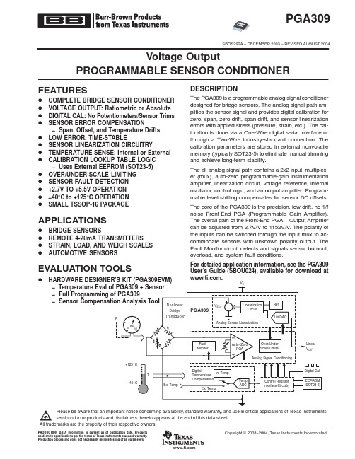
proper handling and installation procedures can cause damage. ESD damage can range from subtle performance degradation to complete device failure. Precision integrated circuits may be more susceptible to damage because very small parametric changes could1s/divV REF =4.096VMeasured After Bandpass Filter 0.1Hz Second−Order High−Pass 10Hz Fourth−Order Low−Pass1s/divG =1152Coarse Offset =−59mVMeasured After Bandpass Filter 0.1Hz Second−Order High−Pass 10Hz Fourth−Order Low−PassV IN =+61mVCLK_CFG=00(default)Gain=1152Time(10µs/div)SMALL−SIGNAL STEP RESPONSEGain=256Time(10µs/div)OVERVOLTAGE RECOVERYV OUTUnit1 Unit2Code(LSB)70000100002000030000400006000050000vs CODEPACKAGING INFORMATIONOrderable Device Status (1)Package Type Package Drawing Pins Package Qty Eco Plan (2)Lead/Ball FinishMSL Peak Temp (3)PGA309AIPWR ACTIVE TSSOP PW 162500Green (RoHS &no Sb/Br)CU SNPB Level-1-260C-UNLIM PGA309AIPWTACTIVETSSOPPW16250Green (RoHS &no Sb/Br)CU SNPBLevel-1-260C-UNLIM(1)The marketing status values are defined as follows:ACTIVE:Product device recommended for new designs.LIFEBUY:TI has announced that the device will be discontinued,and a lifetime-buy period is in effect.NRND:Not recommended for new designs.Device is in production to support existing customers,but TI does not recommend using this part in a new design.PREVIEW:Device has been announced but is not in production.Samples may or may not be available.OBSOLETE:TI has discontinued the production of the device.(2)Eco Plan -May not be currently available -please check /productcontent for the latest availability information and additional product content details.None:Not yet available Lead (Pb-Free).Pb-Free (RoHS):TI's terms "Lead-Free"or "Pb-Free"mean semiconductor products that are compatible with the current RoHS requirements for all 6substances,including the requirement that lead not exceed 0.1%by weight in homogeneous materials.Where designed to be soldered at high temperatures,TI Pb-Free products are suitable for use in specified lead-free processes.Green (RoHS &no Sb/Br):TI defines "Green"to mean "Pb-Free"and in addition,uses package materials that do not contain halogens,including bromine (Br)or antimony (Sb)above 0.1%of total product weight.(3)MSL,Peak Temp.--The Moisture Sensitivity Level rating according to the JEDECindustry standard classifications,and peak solder temperature.Important Information and Disclaimer:The information provided on this page represents TI's knowledge and belief as of the date that it is provided.TI bases its knowledge and belief on information provided by third parties,and makes no representation or warranty as to the accuracy of such information.Efforts are underway to better integrate information from third parties.TI has taken and continues to take reasonable steps to provide representative and accurate informationbut may not have conducted destructive testing or chemical analysis on incoming materials and chemicals.TI and TI suppliers consider certain information to be proprietary,and thus CAS numbers and other limited information may not be available for release.In no event shall TI's liability arising out of such information exceed the total purchase price of the TI part(s)at issue in this document sold by TI to Customer on an annual basis.PACKAGE OPTION ADDENDUM9-Dec-2004Addendum-Page 1元器件交易网元器件交易网IMPORTANT NOTICETexas Instruments Incorporated and its subsidiaries (TI) reserve the right to make corrections, modifications,enhancements, improvements, and other changes to its products and services at any time and to discontinueany product or service without notice. Customers should obtain the latest relevant information before placingorders and should verify that such information is current and complete. All products are sold subject to TI’s termsand conditions of sale supplied at the time of order acknowledgment.TI warrants performance of its hardware products to the specifications applicable at the time of sale inaccordance with TI’s standard warranty. T esting and other quality control techniques are used to the extent TIdeems necessary to support this warranty. Except where mandated by government requirements, testing of allparameters of each product is not necessarily performed.TI assumes no liability for applications assistance or customer product design. Customers are responsible fortheir products and applications using TI components. T o minimize the risks associated with customer productsand applications, customers should provide adequate design and operating safeguards.TI does not warrant or represent that any license, either express or implied, is granted under any TI patent right,copyright, mask work right, or other TI intellectual property right relating to any combination, machine, or processin which TI products or services are used. Information published by TI regarding third-party products or servicesdoes not constitute a license from TI to use such products or services or a warranty or endorsement thereof.Use of such information may require a license from a third party under the patents or other intellectual propertyof the third party, or a license from TI under the patents or other intellectual property of TI.Reproduction of information in TI data books or data sheets is permissible only if reproduction is withoutalteration and is accompanied by all associated warranties, conditions, limitations, and notices. Reproductionof this information with alteration is an unfair and deceptive business practice. TI is not responsible or liable forsuch altered documentation.Resale of TI products or services with statements different from or beyond the parameters stated by TI for thatproduct or service voids all express and any implied warranties for the associated TI product or service andis an unfair and deceptive business practice. TI is not responsible or liable for any such statements.Following are URLs where you can obtain information on other Texas Instruments products and applicationsolutions:Products ApplicationsAmplifiers Audio /audioData Converters Automotive /automotiveDSP Broadband /broadbandInterface Digital Control /digitalcontrolLogic Military /militaryPower Mgmt Optical Networking /opticalnetworkMicrocontrollers Security /securityTelephony /telephonyVideo & Imaging /videoWireless /wirelessMailing Address:Texas InstrumentsPost Office Box 655303 Dallas, Texas 75265Copyright 2004, Texas Instruments Incorporated。
APM5 系列网络电力仪表 安装使用说明书 V1.1
475APM5系列网络电力仪表安装使用说明书V1.1安科瑞电气股份有限公司申明版权所有,未经本公司之书面许可,此手册中任何段落、章节内容均不得被摘抄、拷贝或以任何形式复制、传播,否则一切后果由违者自负。
本公司保留一切法律权利。
本公司保留对本手册所描述之产品规格进行修改的权利,恕不另行通知。
订货前,请垂询当地代理商以获悉本产品的最新规格。
总部:安科瑞电气股份有限公司地址:上海市嘉定区育绿路253号销售电话:************销售手机:187****7862(同微信)柏经理售后服务热线:************上海售后服务部*************江阴售后服务部目录1.概述 (1)1.1型号功能 (1)1.2功能选型 (2)1.3技术参数 (3)2.安装接线 (5)2.1外形及安装尺寸 (5)2.2安装方法 (6)2.3工程施工注意事项 (6)2.3.1电压输入 (6)2.3.2电流输入 (7)2.3.3通讯接线 (7)2.4接线方法 (7)2.4.1接线图 (7)3.操作说明 (12)3.1导航按键字符号说明 (12)3.2菜单显示总览 (12)3.3界面介绍 (14)3.3.1主界面 (14)3.3.2菜单界面 (14)3.3.3矢量图界面 (15)4.查看数据信息 (15)4.1查看事件记录 (15)4.1.1查看DIDO记录 (15)4.1.2查看报警信息 (15)4.1.3查看录波记录: (16)5.参数设置 (16)5.1参数设置界面 (16)5.2输入设置 (17)5.3通信设置 (18)5.4无线设置 (19)5.5报警设置 (19)5.6DO设置 (22)5.7AO设置 (23)5.8复费率设置 (24)5.8.2切换日期设置 (25)5.9录波设置 (26)5.10需量设置 (27)5.11系统设置 (27)5.12清除设置 (29)5.13版本信息 (30)6.Modbus通讯说明 (30)6.1简介 (30)6.2通讯地址表 (30)7.以太网通讯指南 (61)7.1以太网参数修改 (61)7.1.1通过按键修改 (61)7.2Modbus TCP寄存器地址 (61)8.DL/T-645通讯指南 (61)8.1DL/T645-2007协议简述 (61)8.2传输方式 (61)8.3协议 (61)8.3.1数据帧格式 (62)8.3.2传输 (62)8.3.3数据标识表 (63)9.常见故障排查分析 (67)10.包装 (67)1.概述APM5系列网络电力仪表(以下简称仪表)按IEC 国际标准设计,具有全电量测量、电能统计、电能质量分析(包括谐波、间谐波、闪变)、故障录波功能(包括电压暂升暂降中断、冲击电流等记录)、事件记录功能及网络通讯等功能,主要用于电网供电质量的综合监控。
场效应管的代替型号

液晶 8 脚贴片元器件参数大集合
4532 内含 P 沟道、N 沟道 MOS 管各一,高压板用(30V 4.7A;30V 4.5A)
4532M 内含 P 沟道、N 沟道 MOS 管各一,高压板用(30V 4.5A;30V 4.5A)
AO4409(30V15A-P) 30V 15A P 沟道场效应 8 脚贴片
AO4410 30V 18A 单 N 沟道 8 脚贴片
AO4411 30V 8A 3W P 沟道场效应,8 脚贴片
AO4413 30V 15A 3W 单 P 沟道,8 脚贴片
AO4413 30V 15A 3W 单 P 沟道,8 脚贴片
9916H 18V 35A 50W 小贴片 9960GM 8 脚贴片,高压板用。
AF4502CS 内含 P 沟道、N 沟道 MOS 管各一,高压板用(30V 8.4A;30V 6.8A)
AO4403 30V 6.1A 单 P 沟道 8 脚贴片 AO4404 30V 8.5A 单 N 沟道 8 脚贴片
TPC8401 内含 P 沟道、N 沟道 MOS 管各一,高压板用(30V 4.5A;30V 4.5A)
AP1501/AP1506 , 3A 降压 DC/DC ,直接替换 LM2576/LM2596 ,广泛应用于车载 DVD ,车载音响, LCD/LCM ; AP1507 , 3A 降压 DC/DC ,替换 SHARP PQ1CZ21 , PQICZ41 , PQ1CG21 。应用于车 载 DVD ,车载音响; AP1509 , 2A 降压 DC/DC 。替换 MP1410 ;应用于 DVD 译码版,网络产品; AP2001 , CCFL 驱动 IC ,
台湾茂达的产品封装及功能说明

深圳市沛城电子科技有限公司地址:中国广东省深圳市南山区科技园北区清华紫光信息港B座三楼联系人:曾小姐电话:86-755-82990713(直线)总机:86-755-82993060传真: 86-755-82992851E-mail: pcmy2011@MSN:yinhualy@公司网址:阿里旺铺:沛城电子是茂达(ANPEC)授权一级代理商,1、MOSFET(MOS管)APM9435为一颗P-MOSFET,VDS耐压为30V,VGS耐压为25V,提供最大的连续电流为6.2A,在VGS=10V 时,最大导通阻抗为60mΩ,采用无铅的SOP-8封装,主要作为电源的开关和PWM的功率器件的应用,常用在车载电子、LCD、便携DVD等电子产品上. 替代市面上如 CEM9435、AP9435 、AF9435 、GE9435、 GT9435 、TM9435、 MT9435、 SD9435。
APM2300CAC,SOT23封装, N沟道 20V/6A兼容,AO3400,SI2300,ME2314,GN2300,……APM2301CAC,SOT23封装, P沟道 20V/6A, 800MA VIN 2.5-5.5 BUCK PWM,兼容AO3401 ,SI2301,LT3406,RT8008,RT8009,APS1006,MP2104……APM2306,SOT23封装,兼容ME2306,GV2314……APM4412为一颗N-MOSFET,VDS耐压为30V,VGS耐压为20V,提供最大的连续电流为12A,在VGS=10V 时,最大导通阻抗为12mΩ,采用无铅的SOP-8封装,主要作为电源的开关和PWM的功率器件的应用,常用在车载电子、LCD、便携DVD,电子调速器等电子产品上。
APM4953为一颗P-MOSFET,VDS耐压为30V,VGS耐压为25V,提供最大的连续电流为6.2A,在VGS=10V 时,最大导通阻抗为60mΩ,采用无铅的SOP-8封装,主要作为电源的开关和PWM的功率器件的应用,常用在车载电子、LCD、便携DVD等电子产品上.兼容SI4953,AP4953,STM9435,MT9435……APM9926,封装SOP/TSSOP-8,兼容N9926A,应用LED显示屏APM4550:封装SOP8,应用:笔记本,场效应管APM3095:封装SOT252,其他MOSFET(MOS管):APM4953KC SOP8 双P沟道 30V/5A兼容SI4953,AP4953,STM9435,MT9435……APM2305AC SOT23 沟道 16V/3.5A兼容 SI2305……APM3055LUC TO252 N沟 30V/20A兼容STD1703APM3023NUC TO252 N沟道 30V/30A兼容AOD408,AP40T03…APM3095PUC TO252 N沟道 30V/8AAP2014NUC TO252 N沟道 20V/40A兼容SOD434,AP9T18GAPM9410KC SOP8 N沟通道30V/8A,APM4435KC SOP8 P沟道 30V/8AAPM2506NUC TO252 N沟道 25V50A兼容 06N03,AO472,AP86T02, STD70N02,60N03…APM2509NUC TO252 N沟道 25V50A兼容09N03,AO452,AP72T02,STD90N02,70N03…APM7313KC SOP8 双N沟道 30V/6A兼容IRF7313,AO48002、PWM(DC-DC升/降压IC):DC-DC升压IC:APW7077AAPW7077A是一颗升压PWM控制器,超低的启动电压(0.9V),工作电压为(0.9V~5.5V),内置软启动和固定的300K频率,APW7077A本身的驱动能力为150mA,SOT-25封装,和AP1624,NCP1450,XC6368兼容。
sae ams 3095a标准
SAE AMS 3095A标准是什么?1. SAE AMS 3095A标准简介SAE AMS 3095A是由美国汽车工程师学会(SAE)制定的一项标准,它是针对航空航天领域中金属材料的光谱分析的要求。
该标准规定了用于检验金属材料成分的光谱分析的方法和要求,以确保材料的质量和合格性。
2. SAE AMS 3095A标准的适用范围这项标准适用于航空航天领域中使用的各种金属材料,包括铝合金、钛合金、镍合金等。
它涵盖了从材料生产到成品制造的整个生命周期,确保材料符合特定的成分要求,以保证飞机部件的质量和安全性。
3. SAE AMS 3095A标准的具体要求根据SAE AMS 3095A标准,进行光谱分析的设备和方法必须符合一定的要求,包括但不限于以下几点:- 分析仪器必须能够准确测量所涉及的金属材料中的各种元素,包括但不限于铝、镁、铁、硅、镧等。
- 分析方法必须精准可靠,确保测试结果的准确性和可重复性。
- 分析结果必须符合特定的规范要求,以确保材料成分符合设计要求。
4. SAE AMS 3095A标准的意义和应用SAE AMS 3095A标准的制定旨在保证航空航天领域中使用的金属材料的质量和可靠性。
通过严格的光谱分析要求,可以有效地避免杂质和成分偏差对材料性能的影响,保证飞机部件在高强度、高温、高压等复杂环境下的安全可靠运行。
SAE AMS 3095A标准也为材料生产厂家、航空航天制造商以及相关监管部门提供了一致的技术规范和标准化要求,有利于提高产业整体的质量水平和竞争力。
5. SAE AMS 3095A标准的更新和发展随着航空航天领域的发展和技术的进步,金属材料的要求也在不断提高。
SAE AMS 3095A标准也将不断进行更新和完善,以适应新材料、新工艺和新需求的发展。
通过持续改进和更新,SAE AMS 3095A 标准将为航空航天材料分析提供更加可靠和先进的技术支持。
结论SAE AMS 3095A标准作为航空航天领域中材料分析的重要标准,对于保证材料质量、促进产业发展具有重要意义。
IBM磁带产品详细参数

3573L4S(高容量,PN)包括IBM LTO Ultrium 4 LVD Ultra160连接,SCSI磁带驱动器
3573F4S(高容量,PN)包括IBM LTO Ultrium 4的4 Gbps光纤通道磁带驱动器
使用LTO Ultrium 3每个磁带库的容量最高可达38.40TB(压缩);本机容量达19.20TB
数据传输速率
使用全高型和半高型LTO Ultrium 4技术,本机数据传输速率可达120MBps
使用全高型LTO Ultrium 3技术,本机数据传输速率可达80MBps
使用半高型LTO Ultrium 3技术,本机数据传输速率可达60MBps
操作系统支持
为IBM System p®、IBM System i®、IBM System x、Windows Server 2003、Sun Solaris、HP-UX、Red Hat和United Linux提供本机设备驱动程序支持。
TS3310
3576 L5B型
3576 L5B型和4个E9U型
1-4
磁带盒数量
48
I/O插槽数量
3
物理容量
使用LTO Ultrium 4每个磁带盒最高可达1.60TB(压缩);本机为800GB
使用LTO Ultrium 3每个磁带盒最高可达800GB(压缩);本机容量达400GB
使用LTO Ultrium 4每个磁带库的容量最高可达76.80TB(压缩);本机容量达38.40TB
热插拔组件
电源、磁带驱动器
RAID支持
无
系统管理
PGA309中文资料

除非另有说明
+7.0V –0.3V~VSA+0.3V
150mA 10mA 50mA
–60 ~+150 –55 ~+150
+150器件永久性损坏 延长在极限条件下的工作时间会影响器件的可靠性 这些仅仅只 是权限参数 并不意味着在极限条件下或在任何其它超出推荐工作条件所示参数的情况下器件能有效工作
3
武汉力源信息技术服务有限公司
免费电话 800-8808051
续表
4
武汉力源信息技术服务有限公司
免费电话 800-8808051
续表
5
武汉力源信息技术服务有限公司
免费电话 800-8808051
续表
6
评估工具
z 硬件设计套件 PGA309DK 对 PGA309 和传感器进行评估 在整个温度范围内评估
z 软件控制设计套件 对 PGA309 编程以进行评估 对 PGA309 编程以进行首次生产试行 传感器计算分析工具
1
武汉力源信息技术服务有限公司
免费电话 800-8808051
6 查询表允许过温时的多斜率补偿 查询表可使用 17 个校准点 其中包括存储在 16 位数据格式中的 3 个调整值 TX
温度 XMX 零点 DAC(Zero DAC) GMX 增益 17 3 16=查询表的大小
引脚配置
顶视图 TSSOP
引脚描述
引脚 名称
1
VEXC
2
GNDA
3
VSA
4
VIN1
5
VIN2
内部/外部 z 校准参照表查询逻辑
包括线性内插演算法 z 非易失性的校准常量
THS3091中文资料

高电压,低失真,电流反馈运算放大器·低失真- 77 dBc的HD2在10兆赫,RL = 1 K- 69 dBc的在10 MHz的HD3,R L = 1千瓦·低噪音- 14 PA / ÖHz同相电流噪声- 17 PA / ÖHz反相电流噪声- 2 NV / ÖHz电压噪声·高转换率:7300 V /μs的(G = 5 V0 = 20 VPP)·宽带:210兆赫(G = 2,RL = 100瓦)·高输出电流驱动器:± 250毫安·宽电源电压范围:± 5 V至± 15 V的·省电特性:(THS3095只有)·高电压的任意波形·电源FET驱动器·引脚驱动程序VDSL线路驱动器THS3091和THS3095是高电压,低失真,高速电流反馈设计工作在宽电源放大器±5 V的要求大,线性输出信号,如PIN,功率FET,和VDSL线路驱动器的应用到± 15 V的范围内。
THS3095功能掉电引脚(PD)放大器置于低功耗待机模式,降低静态电流从950毫安到500μA。
总谐波结合的宽电源电压范围在10 MHz时为-69 dBc的低失真,除了7300 V /μs的高压摆率使得非常适合用于高电压的任意THS3091 / 5波形驱动器应用。
此外,有处理能力大的电压摆幅,驾驶到高电阻和高电容负载,同时保持良好的稳定时间性能,使这些器件引脚的驱动程序和PowerFET驱动器应用的理想选择。
THS3091和THS3095提供8引脚· VDSL的线路驱动器,采用SOIC(D)和8引脚SOIC(DDA)的包PowerPAD™。
请注意,在得克萨斯州的关键应用的可用性,标准保修,并使用一个重要的通知仪器的半导体产品和免责条款及其出现在此数据表的结束。
PowerPAD是德州仪器的商标。
3095说明书CH
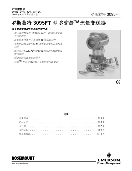
在实际处理条件下可保持 10 年的稳定性
通过主动模拟测试,罗斯蒙特 3095FT 已经向广大客户证明其具有 在大多数要求较高的条件下能够保持出色性能的实力。 绝佳的变送 器稳定性降低了标定的频率,从而降低维护和运行成本。
共面 平台为差压流量计提供支持
这种解决方案已进行工厂标定、压力试验并在开箱后就可立即进行 安装。 只有罗斯蒙特能够提供可降低工程和库存成本的规模可变的 共面变送器设计。
通讯要求 250 欧姆的最小环路电阻。
参考精度 (包括线性度、滞后、重复性 )
(1) 超级流量量程 2 - 3 (选项 U3)
温度极限
过程 • - 40 至 185 °F (- 40 至 85 °C) 环境温度 • - 40 至 185 °F (- 40 至 85 °C) • 配备一体化表头: - 4 至 175 °F (- 20 至 80 °C) 储存温度 • - 50 至 212 °F (- 46 至 100 °C) • 配备一体化表头: - 40 至 185 °F (- 40 至 85 °C)
静压影响
• 零点误差 = ± 0.05% 量程上限 / 1000 psi (6895 kPa) • 量程误差 = ± 0.20% 读数 / 1000 psi (6895 kPa)
启动时间
在向变送器加电后 60 秒内,过程变量就会达到技术规格中规定的 要求。
稳定性
超级流量量程 2 - 3 (选项 U3) (1) • ± 十年稳定性,精度为 ± 0.25% 量程上限,温度变化范围: ±50 °F (28 °C), 线压达到 1000 psi (6895 kPa)。 量程 2 - 3 • ± 五年稳定性,精度为 ± 0.125% 量程上限,温度变化范围: ± 50 °F (28 °C) ,线压达到 1000 psi (6895 kPa)。
LM309中文资料

LM109/LM3095-Volt RegulatorGeneral DescriptionThe LM109series are complete 5V regulators fabricated on a single silicon chip.They are designed for local regulation on digital logic cards,eliminating the distribution problems association with single-point regulation.The devices are available in two standard transistor packages.In the solid-kovar TO-5header,it can deliver output currents in ex-cess of 200mA,if adequate heat sinking is provided.With the TO-3power package,the available output current is greater than 1A.The regulators are essentially blowout proof.Current limiting is included to limit the peak output current to a safe value.In addition,thermal shutdown is provided to keep the IC from overheating.If internal dissipation becomes too great,the regulator will shut down to prevent excessive heating.Considerable effort was expended to make these devices easy to use and to minimize the number of external compo-nents.It is not necessary to bypass the output,although thisdoes improve transient response somewhat.Input bypass-ing is needed,however,if the regulator is located very far from the filter capacitor of the power supply.Stability is also achieved by methods that provide very good rejection of load or line transients as are usually seen with TTL logic.Although designed primarily as a fixed-voltage regulator,the output of the LM109series can be set to voltages above 5V,as shown.It is also possible to use the circuits as the control element in precision regulators,taking advantage of the good current-handling capability and the thermal overload protection.Featuresn Specified to be compatible,worst case,with TTL and DTLn Output current in excess of 1An Internal thermal overload protection n No external components requiredSchematic DiagramDS007138-1April 1998LM109/LM3095-Volt Regulator©1999National Semiconductor Corporation Absolute Maximum Ratings (Note 1)If Military/Aerospace specified devices are required,please contact the National Semiconductor Sales Office/Distributors for availability and specifications.Input Voltage35VPower DissipationInternally LimitedOperating Junction Temperature Range LM109−55˚C to +150˚C LM3090˚C to +125˚C Storage Temperature Range −65˚C to +150˚CLead Temperature (Soldering,10sec.)300˚CElectrical Characteristics (Note 2)ParameterConditionsLM109LM309UnitsMinTyp Max Min Typ Max Output Voltage T j =25˚C 4.75.05 5.3 4.85.05 5.2V Line Regulation T j =25˚C 4.0504.050mV 7.10V ≤V IN ≤25V Load RegulationT j =25˚CTO-39Package 5mA ≤I OUT ≤0.5A 15501550mV TO-3Package5mA ≤I OUT ≤1.5A 1510015100mV Output Voltage7.40V ≤V IN ≤25V, 4.65.44.755.25V5mA ≤I OUT ≤I MAX ,P <P MAXQuiescent Current 7.40V ≤V IN ≤25V 5.210 5.210mA Quiescent Current Change 7.40V ≤V IN ≤25V 0.50.5mA 5mA ≤I OUT ≤I MAX 0.80.8mA Output Noise Voltage T A =25˚C4040µV10Hz ≤f ≤100kHzLong Term Stability 1020mV Ripple Rejection T j =25˚C 5050dBThermal Resistance,(Note 3)Junction to CaseTO-39Package 1515˚C/W TO-3Package2.52.5˚C/WNote 1:“Absolute Maximum Ratings”indicate limits beyond which damage to the device may occur.Operating Ratings indicate conditions for which the device is functional,but do not guarantee specific performance limits.Note 2:Unless otherwise specified,these specifications apply −55˚C ≤T j ≤+150˚C for the LM109and 0˚C ≤T j ≤+125˚C for the LM309;V IN =10V;and I OUT =0.1A for the TO-39package or I OUT =0.5A for the TO-3package.For the TO-39package,I MAX =0.2A and P MAX =2.0W.For the TO-3package,I MAX =1.0A and P MAX =20W.Note 3:Without a heat sink,the thermal resistance of the TO-39package is about 150˚C/W,while that of the TO-3package is approximately 35˚C/W.With a heat sink,the effective thermal resistance can only approach the values specified,depending on the efficiency of the sink.Note 4:Refer to RETS109H drawing for LM109H or RETS109K drawing for LM109K military specifications.Connection DiagramsMetal Can PackagesDS007138-33Order Number LM109H,LM109H/883or LM309HSee NS Package Number H03ADS007138-34Order Number LM109K STEEL orLM309K STEELSee NS Package Number K02A Order Number LM109K/883See NS Package Number K02C2Application Hints1.Bypass the input of the LM109to ground with≥0.2µFceramic or solid tantalum capacitor if main filter capaci-tor is more than4inches away.2.Avoid insertion of regulator into“live”socket if inputvoltage is greater than10V.The output will rise to within 2V of the unregulated input if the ground pin does not make contact,possibly damaging the load.The LM109 may also be damaged if a large output capacitor is charged up,then discharged through the internal clamp zener when the ground pin makes contact.3.The output clamp zener is designed to absorb tran-sients only.It will not clamp the output effectively if a fail-ure occurs in the internal power transistor structure.Ze-ner dynamic impedance is≈4Ω.Continuous RMS current into the zener should not exceed0.5A.4.Paralleling of LM109s for higher output current is notrecommended.Current sharing will be almost nonexist-ent,leading to a current limit mode operation for devices with the highest initial output voltage.The current limit devices may also heat up to the thermal shutdown point (≈175˚C).Long term reliability cannot be guaranteed under these conditions.5.Preventing latchoff for loads connected to negativevoltage:If the output of the LM109is pulled negative by a high cur-rent supply so that the output pin is more than0.5V negative with respect to the ground pin,the LM109can latch off.This can be prevented by clamping the ground pin to the output pin with a germanium or Schottky diode as shown.A silicon diode(1N4001)at the output is also needed to keep the positive output from being pulled too far negative.The10Ωresistor will raise+V OUT by≈0.05V.Crowbar Overvoltage Protection Typical Performance Characteristics DS007138-7Input CrowbarDS007138-8Output CrowbarDS007138-9*Zener is internal to LM109.**Q1must be able to withstand7A continuous current if fusing is not used at regulator input.LM109bond wires will fuse at currents above7A.†Q2is selected for surge capability.Consideration must be given to filter capacitor size,transformer impedance,and fuse blowing time.††Trip point is≈7.5V.Maximum AveragePower Dissipation(LM109K)DS007138-16Maximum AveragePower Dissipation(LM309K)DS007138-17Output ImpedanceDS007138-18 3Typical Performance Characteristics(Continued)Maximum AveragePower Dissipation (LM109H)DS007138-19Maximum AveragePower Dissipation (LM309H)DS007138-20Ripple RejectionDS007138-21Current LimitCharacteristics (Note 5)DS007138-22Thermally Induced Output Voltage VariationDS007138-23Ripple RejectionDS007138-24Note 5:Current limiting foldback characteristics are determined by input output differential,not by output voltage.Input-Output Differential (V)DS007138-25Output Voltage (V)DS007138-26Output Voltage (V)DS007138-27 4Typical Performance Characteristics(Continued)Typical ApplicationsQuiescent CurrentDS007138-28Quiescent CurrentDS007138-29Output Voltage NoiseDS007138-30Line Transient Response DS007138-31Load Transient ResponseDS007138-32Fixed 5V RegulatorDS007138-2*Required if regulator is located more than 4"from power supply filter capacitor.†Although no output capacitor is needed for stability,it does improve transient response.C2should be used whenever long wires are used to connect to the load,or when transient response is critical.Note:Pin 3electrically connected to case.Adjustable Output RegulatorDS007138-45Typical Applications(Continued)High Stability Regulator*DS007138-5*Regulation better than0.01%,load,line and temperature,can be obtained.†Determines zener current.May be adjusted to minimize thermal drift.‡Solid tantalum.Current RegulatorDS007138-6 *Determines output current.If wirewound resistor is used,bypass with0.1µF.6Physical Dimensions inches(millimeters)unless otherwise notedMetal Can Package(H)Order Number LM109H,LM109H/883or LM309HNS Package Number H03AMetal Can Package(K)Order Number LM109K STEEL,LM309K STEELNS Package Number K02A7Physical Dimensionsinches (millimeters)unless otherwise noted (Continued)LIFE SUPPORT POLICYNATIONAL’S PRODUCTS ARE NOT AUTHORIZED FOR USE AS CRITICAL COMPONENTS IN LIFE SUPPORT DE-VICES OR SYSTEMS WITHOUT THE EXPRESS WRITTEN APPROVAL OF THE PRESIDENT OF NATIONAL SEMI-CONDUCTOR CORPORATION.As used herein:1.Life support devices or systems are devices or sys-tems which,(a)are intended for surgical implant intothe body,or (b)support or sustain life,and whose fail-ure to perform when properly used in accordancewith instructions for use provided in the labeling,can be reasonably expected to result in a significant injury to the user.2.A critical component is any component of a life support device or system whose failure to perform can be rea-sonably expected to cause the failure of the life support device or system,or to affect its safety or effectiveness.National Semiconductor Corporation AmericasTel:1-800-272-9959Fax:1-800-737-7018Email:support@National Semiconductor EuropeFax:+49(0)180-5308586Email:europe.support@Deutsch Tel:+49(0)180-5308585English Tel:+49(0)180-5327832Français Tel:+49(0)180-5329358Italiano Tel:+49(0)180-5341680National Semiconductor Asia Pacific Customer Response Group Tel:65-2544466Fax:65-2504466Email:sea.support@National Semiconductor Japan Ltd.Tel:81-3-5639-7560Fax:81-3-5639-7507Metal Can Package (K)Mil-Aero ProductOrder Number LM109K/883NS Package Number K02CL M 109/L M 3095-V o l t R e g u l a t o rNational does not assume any responsibility for use of any circuitry described,no circuit patent licenses are implied and National reserves the right at any time without notice to change said circuitry and specifications.。
P沟道场效应管大全

AO P沟道场效应管系列:AO3401,3401 AO SOT-23 P场 -30V -4.2AAO3403L,AO3403,3403 AO SOT-23 P场 -30V -2.6A AO3407,3407 AO SOT-23 P场 -30V -4.1AAO3409,3409 AO SOT-23 P场 -30V -2.6AAO3413L,AO3413,3413 AO SOT-23 P场 -20V -3A AO3415,3415 AO SOT-23 P场 -20V -4AAO3419,3419 AO SOT-23 P场 -20V -3.5AAO4401,4401 AO SOP-8 P场 -30V -6.1AAO4403,4403 AO SOP-8 P场 -30V -6.1AAO4405,4405 AO SOP-8 P场 -30V -6AAO4407,4407 AO SOP-8 P场 -30V -12AAO4411,4411 AO SOP-8 P场 -30V -8AAO4413,4413 AO SOP-8 P场 -30V -15AAO4415,4415 AO SOP-8 P场 -30V -8AAO4419,4419 AO SOP-8 P场 -30V -9.7AAO4423L,AO4423,4423 AO SOP-8 P场 -30V -15A AO4425,4425 AO SOP-8 P场 -38V -14AAO4429,4429 AO SOP-8 P场 -30V -15AAO4433L,AO4433,4433 AO SOP-8 P场 -30V -11A AO4437,4437 AO SOP-8 P场 -12V -11AAO4701L,AO4701,4701 AO SOP-8 P场 -30V -5AAO6401,6401 AO TSOP-6 P场 -30V -5AAO6405,6405 AO TSOP-6 P场 -30V -5AAO6409,6409 AO TSOP-6 P场 -20V -5AAO6419,6419 AO TSOP-6 P场 -30V -5AAO6701L,AO6701,6701 AO TSOP-6 P场 -30V -2.3AAO7401L,AO7401,7401 AO SOT-323 P场 -30V -1.2AAOD403,D403 AO SOT-252 P场 -30V -85AAOD405,D405 AO SOT-252 P场 -30V -18AAOD407,D407 AO SOT-252 P场 -60V -12AAOD409,D409 AO SOT-252 P场 -60V -26AAOU401,U401 AO TO-251 P场 -60V -20AAOU417,U417 AO TO-251 P场 -30V -18AAP/富鼎 P沟道场效应管系列:AP40P03GH,AP40P03,40P03GH,40P03,SOT-252,AP/富鼎,05NPB,SMD/MOS,-30V,-30A,0.028ΩAP4435M,AP4435M,4435M AP/富鼎 SOP-8 P场 -30V -8AAP9575H,AP9575,9575H AP/富鼎 SOT-252 P场 -60V -15AAP6679H,AP6679,6679H AP/富鼎 SOT-252 P场 -30V -75AAP9563H,AP9563,9563H AP/富鼎 SOT-252 P场 -40V -2.6A AP6679P,AP6679P,6679P AP/富鼎 TO-220 P场 -30V -75AAP20P02GJ,AP20P02,20P02GJ AP/富鼎 TO-251 P场 -20V -18A CET/华瑞 P沟道场效应管系列:CEB05P03,05P03 CET/华瑞 SOT-263 P场 -30V -5AFAIRCHILD/仙童 P沟道场效应管系列:NDB6030PL,SOT-263,FAIRCHILD,SMD/MOS,P场,-30V,-30A,0.025Ω NDB6020P,SOT-263,FAIRCHILD,SMD/MOS,P场,-20V,-24A,0.05Ω FDR838P SOP-8 FAIRCHILD SMD/MOS P场 -20V -8A 0.017ΩFDR838 SOP-8 FAIRCHILD SMD/MOS P场 -20V -8A 0.017Ω838P SOP-8 FAIRCHILD SMD/MOS P场 -20V -8A 0.017ΩFDS4435 FAIRCHILD SOP-8 P场 -30V -9AFDS6685 FAIRCHILD SOP-8 P场 -30V -8.8ANDS8435 FAIRCHILD SOP-8 P场 0 0NDS9435A,NDS9435 FAIRCHILD SOP-8 P场 -30V -5.3AFDN336P,FDN336 FAIRCHILD SOT-23 P场 -30V -1.3AFDN340P,FDN340 FAIRCHILD SOT-23 P场 -20V -2ANDC652P,NDC652 FAIRCHILD SOT-23-6 P场 -20V -1.3AD10P05 FAIRCHILD SOT-252 P场 -50V -10AD15P05 FAIRCHILD SOT-252 P场 -50V -15AFDD5614P,FDD5614 FAIRCHILD SOT-252 P场 -60V -15AFDD6637 FAIRCHILD SOT-252 P场 -35V -55AFQD17P06,17P06,D17P06 FAIRCHILD SOT-252 P场 -60V -17AFQD3P50,3P50,D3P50 FAIRCHILD SOT-252 P场 -500V -2.1ARFD10P03L,RFD10P03,10P03 FAIRCHILD SOT-252 P场 -30V -10A SFR9034 FAIRCHILD SOT-252 P场 -60V -14ASFR9224TM,SFR9224 FAIRCHILD SOT-252 P场 -250V -2.5ASFR9310 FAIRCHILD SOT-252 P场 -400V -1.5ANDB6030PL,NDB6030 FAIRCHILD SOT-263 P场 -30V -30ARFP15P05,15P05 FAIRCHILD TO-220 P场 -50V -15ASFP9634 FAIRCHILD TO-220 P场 -250V -5ASFS9630 FAIRCHILD TO-220F P场 -200V -6.5ASFS9634 FAIRCHILD TO-220F P场 -250V -3.4AFQU11P06TU,FQU11P06,11P06 FAIRCHILD TO-251 P场 -60V -11A FQU17P06,U17P06,17P06 FAIRCHILD TO-251 P场 -60V -12ARFD15P05,15P05 FAIRCHILD TO-251 P场 -50V -15ASFU9214 FAIRCHILD TO-251 P场 -250V -2.7ARFD17P06,17P06 FAIRCHILD TO-251短 P场 -60V -17AHIT P沟道场效应管系列:2SJ295,J295 HIT TO-220F P场 -60V -30A2SJ528S,2SJ528,J528 HIT SOT-252 P场 -60V -7A2SJ245,J245 HIT SOT-252 P场 -60V -5A2SJ529,J529 HIT SOT-252 P场 0 0infineon/英飞凌 P沟道场效应管系列:IPP100P03P3L-04,IPP100P03P3L,IPP100P03,100P03,TO-220, infineon,08NPB,P场,-30V,-100A,0.0043Ω3P03L04,TO-220,infineon,08NPB,P场,-30V,-100A,0.0043Ω SPD08P06P,SPD08P06,D08P06 infineon SOT-252 P场 -60V -8.8ASPD09P06P,SPD09P06,09P06 infineon SOT-252 P场 -60V -9ASPD18P06P,SPD18P06,18P06 infineon SOT-252 P场 -60V -18A SPD30P06P,SPD30P06,30P06 infineon SOT-252 P场 -60V -30A SPD50P03L,SPD50P03,50P03 infineon SOT-252-5 P场 -30V -50A SPB08P06P,SPB08P06,08P06 infineon SOT-263 P场 -60V -8ASPB80P06P,SPB80P06,80P06 infineon SOT-263 P场 -60V -80A intersil P沟道场效应管系列:IRF9540S,IRF9540,F9540 intersil SOT-263 P场 -100V -23ARFD10P03L,RFD10P03,10P03 intersil TO-251 P场 -30V -10AIR P沟道场效应管系列:IRL5602STRR,SOT-263,IR,SMD/MOS,-20V,-24A,P场,0.042ΩIRF9510STRL,SOT-263,IR,SMD/MOS,-100V,-4A,P场,1.2ΩIRFL9014,FL9014 IR SOT-223 P场 -60V -1.8AIRLML6401,LML6401 IR SOT-23 P场 12V 4.3AIRFR5305PBF,IRFR5305,FR5305 IR SOT-252 P场 -55V -31AIRFR5505,FR5505 IR SOT-252 P场 -55V -18AIRFR6215,FR6215 IR SOT-252 P场 -150V -13AIRFR9014N,IRFR9014,FR9014,FR9014N IR SOT-252 P场 -60V -5.1A IRFR9024N,FR9024N,IRFR9024 IR SOT-252 P场 -60V -8.8AIRFR9024NTRPBF,IRFR9024NTR,FR9024 IR SOT-252 P场 -60V -8.8A IRFR9110N,IRFR9110,FR9110 IR SOT-252 P场 -100V 3.1AIRFR9120N,IRFR9120,FR9120N,FR9120 IR SOT-252 P -100V -5.6AIRFR9210,FR9210 IR SOT-252 P场 -200V -1.9AIRFR9220,FR9220 IR SOT-252 P场 -200V -3.6AIRF4905NS,F4905NS IR SOT-263 P场 -55V -64AIRF5305STRL,IRF5305S,F5305S IR SOT-263 P场 -55V -31AIRF9530NS,F9530NS IR SOT-263 P场 -100V -14AIRF9640NS,IRF9640N,F9640NS IR SOT-263 P场 -200V -11AIRF9Z34S,F9Z34S IR SOT-263 P场 -60V -18AIRL5602S,IRL5602,L5602S,L5602 IR SOT-263 P场 -20V -24AIRF4905PBF,IRF4905,F4905 IR TO-220 P场 -55V -74AIRF5305PBF,IRF5305,F5305 IR TO-220 P场 -55V -31AIRF9510,F9510 IR TO-220 P场 -100V -4AIRF9530,F9530 IR TO-220 P场 -100V -14AIRF9540N,F9540N,IRF9540,IRF9540PBF IR TO-220 P场 -100V -23A IRF9610,F9610 IR TO-220 P场 -200V -1.8AIRF9640,F9640 IR TO-220 P场 -200V -11AIRF9Z34PBF,IRF9Z34,F9Z34 IR TO-220 P场 -60V -18AIRFI9630G,IRFI9630,FI9630 IR TO-220F P场 -200V -4.3AIRFU5505,FU5505 IR TO-251 P场 -55V -18AIRFU9024N,IRFU9024,FU9024N,FU9024 IR TO-251 P场 -60V -8.8A IRFU9220N,IRFU9220,FU9220N,FU9220 IR TO-251 P场 -200V -3.6A IRF4905S,F4905S IR TO-262 P场 -55V -64AMOT P沟道场效应管系列:MTB50P03HDLT4G,MTB50P03,50P03 MOT SOT-263 P场 -30V -50A NRC P沟道场效应管系列:2SJ132,J132 NEC TO-251 P场 -30V -2A2SJ325,J325 NEC TO-251 P场 -30V -4A2SJ325-Z-E2,2SJ325-Z,J325-Z NEC SOT-252 P场 -30V -4A2SJ326,J326 NEC TO-251 P场 -60V -2A2SJ327-Z,2SJ327,J327-Z,J327 NEC SOT-252 P场 -60V -4A2SJ460TA,2SJ460,J460 NEC TO-92S P场 -50V -0.1A2SJ599,J599 NEC TO-251 P场 -60V -20A2SJ600-Z,2SJ600,J600-Z,J600 NEC SOT-252 P场 -20V -25AON P沟道场效应管系列:NTF2955T1,NTF2955 ON SOT-223 P场 -60V -1.2ANTD2955 ON SOT-252 P场 -60V -12ANTD25P03LT4,NTD25P03L,NTD25P03,D25P03L,D25P03,25P03 ON SOT-252 P场 -30V -25ANTD20P06LT4,NTD20P06L,NTD20P06,D20P06L,D20P06,20P06 ON SOT-252 P场 -60V -20ASANYO P沟道场效应管系列:2SJ653,J653,SANYO,-60V,-37A,P MOS,25mΩ2SJ634,J634 SANYO SOT-252 P场 -60V -8A2SJ591,J591 SANYO TO-220F P场 -60V -28A2SJ652,J652 SANYO TO-220F P场 -60V -28A2SJ653,J653 SANYO TO-220F P场 -60V -37ATM P沟道场效应管系列:TM9435AD,TM9435 TM SOT-252 P场 -30V -10ATOSHIBA/东芝 P沟道场效应管系列:TPC6103,SOT-23-6, -12V, -5.5A,0.035Ω2SJ377-Z,2SJ377,J377-Z,J377 TOSHIBA SOT-252 P场 -60V -5A 2SJ439-Z,2SJ439,J439-Z,J439 TOSHIBA SOT-252 P场 -16V -5A VISHAY/威士 P沟道场效应管系列:SUM110P04-04L-E3,SUM110P04,110P04 VISHAY SOT-263 P场 -40V -110ASUP75P05-08,SUP75P05,75P05 VISHAY TO-220 P场 -50V -75A SUP75P03-07,SUP75P03,75P03 VISHAY TO-220 P场 -30V -75A SUP65P04-15-E3,SUP65P04,65P04 VISHAY TO-220 P场 -40V -65A SI4467DY-T1,SI4467DY,SI4467 VISHAY SOP-8 P场 -12V -12A茂达 P沟道场效应管系列:APM3095P,APM3095 茂达 SOT-252 P场 -30V -6A。
MAXIM MAX3095 MAX3096 说明书

MAX3095/MAX3096
_______________Ordering Information
PART TEMP. RANGE PIN-PACKAGE MAX3095CPE+ 0°C to +70°C 16 Plastic DIP MAX3095CSE+ 0°C to +70°C 16 Narrow SO MAX3095CEE+ 0°C to +70°C 16 QSOP MAX3095EPE+ -40°C to +85°C 16 Plastic DIP MAX3095ESE+ -40°C to +85°C 16 Narrow SO MAX3095EEE+ -40°C to +85°C 16 QSOP MAX3096CPE+ 0°C to +70°C 16 Plastic DIP MAX3096CSE+ 0°C to +70°C 16 Narrow SO MAX3096CEE+ 0°C to +70°C 16 QSOP MAX3096EPE+ -40°C to +85°C 16 Plastic DIP MAX3096ESE+ -40°C to +85°C 16 Narrow SO MAX3096EEE+ -40°C to +85°C 16 QSOP +Denotes a lead(Pb)-free/RoHS-compliant package.
________________Functional Diagram
VCC
G G A1
MAX3095 MAX3096
Y1
Pin Configuration
nce3095k场效应管参数
nce3095k场效应管参数(实用版)目录1.场效应管的基本概念2.nce3095k 场效应管的主要参数3.nce3095k 场效应管参数的测试方法4.nce3095k 场效应管参数对电路性能的影响5.总结正文一、场效应管的基本概念场效应管(Field Effect Transistor,简称 FET)是一种半导体器件,是基于半导体材料的电子运动方式而设计的。
场效应管是三种主要的晶体管之一,另外两种是双极晶体管和绝缘栅双极晶体管。
场效应管具有高输入电阻、低噪声和低功耗等特点,在电路设计中有着广泛的应用。
二、nce3095k 场效应管的主要参数ce3095k 是一种常见的场效应管型号,其主要参数包括:1.漏极电流(ID):漏极电流是指在特定电压下通过场效应管的电流。
nce3095k 的漏极电流通常在几毫安到几十毫安之间。
2.源极电流(IS):源极电流是指在特定电压下从场效应管的源极流入的电流。
nce3095k 的源极电流通常很小,通常在几纳安到几十纳安之间。
3.栅极电流(IG):栅极电流是指在特定电压下通过场效应管栅极的电流。
nce3095k 的栅极电流通常很小,通常在几纳安到几十纳安之间。
4.跨导(gm):跨导是指在特定电压下,栅极电流与漏极电流之比。
nce3095k 的跨导通常在几毫欧姆到几十毫欧姆之间。
5.输出电阻(ro):输出电阻是指场效应管的漏极电流与漏极电压之比。
nce3095k 的输出电阻通常在几十欧姆到几百欧姆之间。
三、nce3095k 场效应管参数的测试方法要测试 nce3095k 场效应管的参数,需要使用一些专业的测试设备,例如数字万用表、示波器和半导体参数测试仪等。
测试步骤如下:1.将场效应管连接到测试电路中。
2.测量漏极电流:在特定的电压下,使用数字万用表或示波器测量漏极电流。
3.测量源极电流:在特定的电压下,使用数字万用表或示波器测量源极电流。
4.测量栅极电流:在特定的电压下,使用数字万用表或示波器测量栅极电流。
- 1、下载文档前请自行甄别文档内容的完整性,平台不提供额外的编辑、内容补充、找答案等附加服务。
- 2、"仅部分预览"的文档,不可在线预览部分如存在完整性等问题,可反馈申请退款(可完整预览的文档不适用该条件!)。
- 3、如文档侵犯您的权益,请联系客服反馈,我们会尽快为您处理(人工客服工作时间:9:00-18:30)。
RDS(ON)-On-Resistance (Ω)
On-Resistance vs. Drain Current
0.24
0.21
0.18 -VGS=4.5V
0.15
0.12 -VGS=10V
0.09
0.06
0.03
0.00 012345678
-VSD -Source-to-Drain Voltage (V)
Power (W)
Single Pulse Power
250
200
150
100
50
0 1E-3 0.01
0.1 1 10
Time (sec)
100 1000
Normalized Effective Transient Thermal Impedance
2.18
2.39
0.89
1.27
0.508
0.89
5.207
5.461
0.46
0.58
0.46
0.58
5.334
6.22
6.35
6.73
3.96
5.18
9.398
10.41
0.51
0.64
1.02
0.89
2.032
Copyright ANPEC Electronics Corp.
6
Rev. A.1 - Oct., 2002
Symbol PD
TJ TSTG RθjA
Parameter Maximum Power Dissipation TA=25°C
TA=100°C Maximum Junction Temperature Storage Temperature Range Thermal Resistance – Junction to Ambient
Symbol
Parameter
Rating
Unit
VDSS VGSS
Drain-Source Voltage Gate-Source Voltage
-30 V
±25
ID*
Maximum Drain Current – Continuous
IDM
Maximum Drain Current – Pulsed
1.Duty Cycle, D=t1/t2 2.Per Unit Base=RthJA=50°C/W 3.TJM-TA=PDMZthJA
100
1000
Copyright ANPEC Electronics Corp.
5
Rev. A.1 - Oct., 2002
元器件交易网
VDD=-15V , IDS=-1A , VGEN=-10V , RG=6Ω RL=15Ω
Input Capacitance
VGS=0V
Output Capacitance
VDS=-25V
Reverse Transfer Capacitance Frequency=1.0MHz
Notes a : Pulse test ; pulse width ≤300µs, duty cycle ≤ 2% b : Guaranteed by design, not subject to production testing
-ID - Drain Current (A)
Copyright ANPEC Electronics Corp.
3
Rev. A.1 - Oct., 2002
元器件交易网
APM3095P
Typical Characteristics
RDS(ON)-On-Resistance (Ω)
Rating 50 20 150
-55 to 150 50
Unit
W
°C °C °C/W
Electrical Characteristics (TA = 25°C unless otherwise noted)
Symbol
Parameter
Test Condition
Static
BVDSS
Drain-Source Breakdown Voltage
VGS=0V , IDS=-250µA
IDSS VGS(th) IGSS
Ra DS(ON)
Zero Gate Voltage Drain Current Gate Threshold Voltage Gate Leakage Current
Drain-Source On-state
Resistance
On-Resistance vs. Gate-to-Source Voltage
0.30 -ID=3A
0.25
0.20
0.15
0.10
0.05
0.00
0
2
4
6
8
10
-VGS - Gate-to-Source Voltage (V)
RDS(ON)-On-Resistance (Ω) (Normalized)
Package Code U : TO -252
O perating Junction T em p. R ange C : -55 to 150°C
H andling C ode TU : Tube TR : Tape & Reel
XXXX X - Date C ode
Absolute Maximum Ratings (TA = 25°C unless otherwise noted)
-12 A
-30
* Surface Mounted on FR4 Board, t ≤ 10 sec.
ANPEC reserves the right to make changes to improve reliability or manufacturability without notice, and advise customers to obtain the latest version of relevant information to verify before placing orders.
2
Rev. A.1 - Oct., 2002
元器件交易网
APM3095P
Typical Characteristics
-ID-Drain Current (A)
Output Characteristics
10 -VGS=5,6,7,8,9,10V
Ordering and Marking Information
GD S
Top View of TO-252
S
G
DD
P-Channel MOSFET
APM 3095P
APM3095P U :
H andling C ode Temp. Range Package Code
A P M 3095P XXXXX
Min. 0.086 0.035 0.020 0.205 0.018 0.018 0.210 0.250 0.156 0.370 0.020 0.025 0.035
Copyright ANPEC Electronics Corp.
1
Rev. A.1 - Oct., 2002
元器件交易网
APM3095P
Absolute Maximum Ratings Cont. (TA = 25°C unless otherwise noted)
元器件交易网
APM3095P
P-Channel Enhancement Mode MOSFET
Features
Pin Description
•
-30V/-6A
,
RDS(ON)=95mΩ(typ.)
@
V =-10V GS
RDS(ON)=140mΩ(typ.)
@
V =-4.5V GS
APM3095P Unit
Min. Typ. Max.
-30
V
-1
µA
-1 -1.5 -2
V
±100 nA
95 110 mΩ
140 160
-0.7 -1.3
V
8
13
1.9
nC
1.1
10 20
8
20
ns
25 50
5
15
550
120
pF
75
Copyright ANPEC Electronics Corp.
Total Gate Charge Gate-Source Charge Gate-Drain Charge
VDS=-15V , IDS=-3A VGS=-10V
Turn-on Delay Time Turn-on Rise Time Turn-off Delay Time Turn-off Fall Time
APM3095P
Packaging Information
TO-252( Reference JEDEC Registration TO-252)
E b2
L2
A C1
b e1
D H
L1 L
C A1
Dim
A A1 b b2 C C1 D E e1 H L L1 L2
Millimeters
Min.
Max.
700
600
Ciss
500
400
300
200 Coss
100
Crss
0
0
5 10 15 20 25 30
-VDS - Drain-to-Source Voltage (V)
