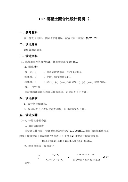
C25说明书3 (1)
Schneider Electric C25 Series定义式接触器说明书
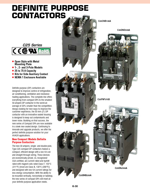
Definite PurPose ContaCtorsl Open Style with Metal Mounting Platel 1-, 2- and 3-Pole Models l 25 to 75 A Capacityl Kits for Side Auxiliary Contact l NEMA 1 Enclosure AvailableDefinite purpose (DP) contactors aredesigned to improve control of refrigeration, air conditioning, ventilation and resistance heating applications. The complete line offers everything from compact DPs to the smallest 50 ampere DP contactor in the world anaverage of 20% smaller than the competition. Always looking for new ways to improve the customer experience, the 50 mm (2") DP contactor with an innovative sealed housing is designed to keep out contaminants and lower noise. Building on that success, the new series of Compact DPs are now available in a sleek new sealed design. Continuing to innovate and upgrade products, we offer the perfect definite purpose solution for your HVACR applications.New Compact Models Definite Purpose ContactorsThe new 30 ampere, single- and double-pole, Type C25 compact DP contactors feature a compact, efficient design with a low VA coil and straight through wiring. These devices are economically priced, UL recognized/CSA certified, are current rated and hp/kW rated with magnet coils rated Class F, 155°C (311°F) [most are Class B, 130°C (266°F)] and designed with low VA current ratings for less energy consumption. With the ability to be mounted vertically, horizontally or tabletop, the new series of compact DPs will meet all your definite purpose application needs.C25BNB230AC25DND330AC25FNF375BC25DNJ350AC25CNB130AComPaCt seriesLightiNg Duty RAtiNgSC25CNB130AC25BNB230ASPECifiCAtiONSCOMPACt MODELSuL Recognized Components: UL File number E1491, Guides NLDX2 and NLDX8CSA Certified Components: CSA C22.2 No. 14-05, File number 238083 Class 3211 84iEC: 60947-4-1EN: 60947-4-1ARi: 780/790 Standard RohS: Compliantinsulation Voltage: 690VCurrent Rated and hp/kW Rated Contacts: Double breakMagnet Coil: Class F, 155°C (311°F)Contact Arc Covers: Standard on all contactorsContactors are Marked with Line and Load terminal Designations Operating temperature Range: -13 to 158°F (-25 to 70°C)tERMiNAL WiRE RANgEhex Washer head Screws: 16-10 AWG, 30 lb-in torque rating Box Lugs:16-10 AWg: 35 lb-in torque rating 8 AWg: 40 lb-in torque rating 6-4 AWg: 45 lb-in torque ratingMounting Position: Vertical, horizontal or tabletopiEC/CE RAtiNgS (iEC 60947-4-1, EN 60947-4-1)C25FNF375AC25DNJ350AStANDARD SERiESuL Recognized Components: UL File #E-1491, Guide NLDX2CSA Certified Components:File #LR353, Class 3211 04, 481301 and 122201iEC: 60947-4-1EN: 60947-4-1RohS Compliance: 25 to 50 A only Magnet CoilClass B: (C25E, F, G, H and K), 130°C (266°F)Class f: (C25D and L), 155°C (311°F) Class h: (C25D), 180°C (356°F) (Available as factory installed option)Contacts: Double break Coil terminals: 10-14 AWG Ambient temperature: 65°C (150°F) maximumApprovals: UL recognized, CSA certified and conform to ARI 780 CE mark terminal Wire Range#8–32 Screw/Pressure Plate: 1-Conductor: 14–8 AWG 2-Conductors: 14–8 AWGBox Lugs—15 to 50 A: #2 posidrive screw or 5⁄32 hex socket screw upper Level: 14-4 AWG (1-conductor)Lower Level: 14-6 AWG (1-conductor)Box Lugs—75 Aupper Level: 14–2 AWG Lower Level: 14–6 AWGNote: The box lugs on the 25–75A device can accept two conductors per pole.C25DND330ALightiNg Duty RAtiNgSstanDarD seriesC25DNJ350AC25BNB230AC25DND330A。
C25普通混凝土配合比计算书(天助)

隧道工程C25普通混凝土配合比计算说明书一、设计依据:1、JGJ 55-2000《普通混凝土配合比设计规程》。
2、JGJ041-2000《公路桥涵施工技术规范》,JTG F60-2009《公路隧道施工技术规范》。
3、其它相关规程及规范。
4、设计坍落度为50~70mm。
二、主要使用材料:1.水泥:重庆天助水泥P.042.5R, 28d抗折强度8.0 Mpa,28d抗压强度48.3Mpa。
2.细集料:兴辉料场河砂:Mx:2.8,含泥量:3.6%。
3.粗集料:聚力料场山碎石4.75~31.5mm。
4.水:清彻无污染河水。
三、配制强度计算:fcu,o ≥fcu,k+1.645σ(σ值根据经验取5)fcu,o=25+1.645*5fcu,o=33.2Mpa四、计算水灰比(αa =0.46 αb=0.07):w/c=αa * fce/( fcu,o+αa*αb*fce) 根据现场工程施工工艺和规范及设计要求,最后采用w/c =0.54。
五、选择用水量:根据恒用水量原则,以及砼坍落度和施工工艺,最后确定用水量为mwo =193kg六、确定水泥用量:m co =mwo/( w/c)=193/0.54=358(kg )七、确定砂率:根据公路桥涵施工技术规范,普通混凝土βs宜选择37%βs=mso /(mgo+mso)*100% =37%八、确定粗骨料、细骨料的用量:当采用重量法时,应按下列公式计算:mco + mso+ mgo+mwo= mcpmcp为每立方米混凝土拌合物的假定重量,其值可取2400~2500kg。
九、确定基准配合比:mco : mso: mgo: mwo=358 : 700 : 1190 : 193十、基准配合比试配调整:根据水灰比的变化以基准配合比的W/C增减0.05作为另两组混凝土的水灰比,此时砂率作相应的调整(±1%),试拌结果如下:当W/C=0.49时;m co1 : mso1: mgo1: mwo1=394 : 676 : 1183 : 193当W/C=0.59时;m co2 : mso2: mgo2: mwo2=327 : 716 : 1180 : 193根据试块抗压强度结果,最终确定配合比为:m co : mso: mgo: mwo= 358 : 700 : 1190 : 193计算人: 复核人:。
C25-8.83-0.981型汽机运规(南汽)
30MW汽机运规一、本规程编写依据1、水利电力部颁发的《汽轮机运行规程》及《电力工业标准汇编》2、南京汽轮电机集团公司C25-8.83/0.981型汽轮机产品说明书。
3、南京汽轮电机集团公司C25-8.83/0.981型汽轮机调节系统说明书。
4、各辅助设备制造厂产品说明书。
二、下列人员应熟悉并熟知本规程1、汽机车间全体运行人员2、汽机车间主任、副主任3、安技科科长、助理、各相关专业专工、值长本规程自下发之日起执行,试行期一年。
目录1 汽轮发电机组及辅助设备规范及主要性能1.1 汽轮发电机组设备规范及主要技术性能1.2 辅助设备规范1.3 汽轮机本体及系统概述1.4 调节保安系统概述2 汽轮机组的启停操作及正常维护2.1 汽轮机组的启机及运行2.2 汽轮机组的停机2.3 辅助设备的运行2.4 机电联系信号的使用说明3 事故处理4 汽轮机组相关试验5 公用系统6 循环水泵的运行附件Ⅰ汽机设备定期切换及试验附件Ⅱ附属机械轴承振动(双振幅)标准附件Ⅲ压力与饱和温度对照表附件Ⅳ典型工况热平衡图Pe=1.255MPa(a)De=0t/hPe=0.981MPa(a)De=40t/hPe=1.05MPa(a)De=30t/hPe=1.13MPa(a)De=20t/h附件Ⅴ工况图附件Ⅵ各种修正曲线附件Ⅶ工业抽汽温度、压力曲线附件Ⅶ调节级配汽曲线附件Ⅸ冷态滑参数启动曲线附件Ⅹ热态滑参数启动曲线附件Ⅺ C25-8.83/0.981型机组滑参数停机时新蒸汽参数的滑降表第一章汽轮发电机组及辅助设备规范及主要性能1 汽轮发电机组设备规范及主要技术性能1.1 汽轮机设备规范型号C25-8.83/0.981型式高压、单缸、单抽汽、冷凝式额定功率25 MW最大功率30 MW主汽门前蒸汽压力8.83±0.49 MPa主汽门前蒸汽温度535℃纯冷凝工况排汽压力4.7 KPa抽汽工况排汽压力 4.40 KPa额定工业抽汽压力0.981 MPa额定工业抽汽温度275.5 ℃额定工业抽汽量80 t/h最大工业抽汽量130 t/h冷却水温度20℃(额定)33 ℃(最高)锅炉给水温度221℃(额定工况)202℃(纯冷凝工况)汽耗 6.045(额定工况)3.841(纯冷凝工况)热耗7093(额定工况)10011(纯冷凝工况)冷却水量5600 t/h额定转速r/min 3000汽轮机转向顺时针从机头向机尾汽轮机转子临界转速1807 r/min(每台机组略有不同)轴系一阶转速(汽轮机) 2148 r/min轴系一阶转速(发电机) 1883 r/min轴承振动0.03 mm过临界允许最大振动0.15 mm通流级数21级1级调节级20级压力级回热级数6级2台高加1台除氧器3台低加汽轮机中心高距运转平台800 mm汽轮机本体最大尺寸(长×宽×高) 8152×4890×4314 mm汽轮机本体总重106 T汽轮机上半总重25 T(连同隔板)汽轮机下半总重26 T(连同隔板)汽轮机转子总重15 T制造厂家南京汽轮机厂1.2 回热抽汽各级参数1.3 调节保安系统的主要技术规范主油泵进口油压0.098 MPa主油泵出口油压1.568 MPa转速不等率4±1 %迟缓率0.5 %油动机最大行程210 mm危急遮断器动作转速3270-3330 r/min危急遮断器复位转速3055 r/min喷油试验时危急遮断器动作转速2920±30 r/min转速表超素保护值3270 r/min(停机值)转子轴向位移报警值+1.0或-0.6 mm 负为反向转子轴向位移报警值+1.3或-0.7 mm 停机值润滑油压降低报警值0.05-0.055 MPa 自启交流润滑油泵润滑油压降低报警值0.04 MPa 自启直流润滑油泵润滑油压降低保护值0.02-0.03 MPa 停机润滑油压降低保护值MPa 0.015 停盘车润滑油压高0.16MPa 报警值停高压油泵润滑油压高0.078 MPa 报警值主油泵出口油压低1.3 MPa报警值主油泵出口油压低1.0 MPa 自启高压油泵轴承回油温度高65℃报警值轴承回油温度高75℃停机值轴瓦温度高105℃报警值轴瓦温度高110℃停机值胀差报警+3 正向-2 负向主油箱油位高+150 mm报警值主油箱油位高-100 mm 报警值低真空保护排汽真空低Ⅰ值MPa -0.087 报警值排汽真空低Ⅱ值MPa -0.073 报警值排汽真空低Ⅲ值MPa -0.061 停机值轴承振动0.06 mm 报警值1.4 发电机及励磁机设备技术规范1.4.1 发电机设备规范型号QFW-30-2C额定功率30000 KW额定电压 6.3 KV额定电流3436.6 A频率50 HZ容量37.5 MVA功率因数0.8励磁电流408 A额定转速3000 r/min产品标准GB/T7064-1996绝缘/使用等级F/B接线法Y1.4.2 交流励磁机设备规范型号TFLW118-3000A额定功率118 KW额定电压246 V额定电流480 A额定频率HZ 150额定转速r/min 3000励磁电压V 48.5励磁电流 A 6.15防护等级IP54绝缘/使用等级F/F接线方式Y重量1343 Kg1.4.3发电机永磁机设备规范型号TFY2.85-3000C功率 2.85 KW额定转速3000 r/min频率400 HZ额定电压V 190额定电流15 A励磁电压V 190功率因数0.9绝缘等级 F相数 12 辅助设备规范2.1 冷凝器设备规范型号N-2000-1型式分列两道制表面回热式冷却面积2000 m2冷却水量5600 t/h 淡水冷却水温度20 ℃冷凝器压力0.0047~0.0048 MPa(绝对压力)汽轮机排汽流量67.28 t/h凝结水温度30.8 ℃过冷度℃ 1汽轮机排汽压力0.0049 MPa排汽口背压0.005 MPa(绝对压力)冷却管数量3920根冷却水流速 1.68 m/S2.2 汽封加热器设备规范型号JQ-23-1设计冷却水量50 t/h冷却水最大压力 1.2 MPa加热面积23 m22.3 空气冷却器设备规范型号STKLQZ冷却面积154.1 m2工作压力(管侧)0.36 MPa2.4 油系统设备规范2.4.1 主油箱设备规范主油箱净重3327 Kg油箱容积正常油位12m3 最高油位12m3 外形尺寸4326×1512×3005(mm)2.4.2 冷油器设备规范型号YL-40冷却面积40m2油量800 L/min冷却水量117.5 t/H出口油温40±5℃2.5 加热器设备规范3 汽轮机本体及系统概述3.1 汽轮机主要结构概述汽轮机结构包括静止部分和转子部分。
电解质开关与启动器(15-360A,两、三、四极)C25产品选择指南说明书
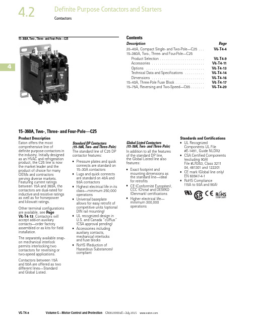
415–360A, Two-, Three- and Four-Pole—C25ContentsDescription Page20–40A, Compact Single- and Two-Pole—C25 . . .V5-T4-415–360A, Two-, Three- and Four-Pole—C25Product Selection . . . . . . . . . . . . . . . . . . . . . . .V5-T4-9Accessories . . . . . . . . . . . . . . . . . . . . . . . . . . .V5-T4-11Options . . . . . . . . . . . . . . . . . . . . . . . . . . . . . .V5-T4-13Technical Data and Specifications . . . . . . . . . .V5-T4-14Dimensions . . . . . . . . . . . . . . . . . . . . . . . . . . .V5-T4-1615–40A, Three-Pole Fuse Block . . . . . . . . . . . . . . .V5-T4-1715–75A, Reversing and Two-Speed—C65 . . . . . . .V5-T4-2015–360A, Two-, Three- and Four-Pole—C25Product DescriptionEaton offers the mostcomprehensive line ofdefinite purpose contactors inthe industry. Initially designedas an HVAC and refrigerationproduct, the C25 line is nowthe market leader and theproduct of choice for manyOEMs and contractorsserving diverse markets.Featuring current ratingsbetween 15A and 360A, thecontactors are dual-rated forinductive and resistive ratingsas well as for horsepowerand kilowatt ratings.Other terminal configurationsare available, see PageV5-T4-13. Contactors willaccept add-on auxiliarycontacts—order factoryassembled or as kits for fieldinstallation.The separately available snap-on mechanical interlockpermits interlocking twocontactors for reversing ortwo-speed applications.Contactors between 15Aand50A are offered as twodifferent lines—Standardand Global Listed.Standard DP Contactors(15–50A, Two- and Three-Pole)The standard line of C25 DPcontactor features:●Pressure plates and quickconnects are standard on15–30A contactors●Lugs and quick connectsare standard on 40A and50A contactors●Highest electrical life in itsclass—minimum 250,000operations●Universal baseplateallows for easy retrofit ofcompetitive units (optionalDIN rail mounting)●UL recognized design inU.S. and Canada “cURus”(CSA approval pending)●Accessories includingauxiliary contacts,mechanical interlocksand fuse blocks●RoHS (Reduction ofHazardous Substances)compliantGlobal Listed Contactors(15–50A, Two- and Three-Pole)In addition to all the featuresof the standard DP line,the Global Listed line alsofeatures:●Exact footprint andmounting dimensions asthe standard line—idealfor retrofits●CE (Conformité Européen),CCC (China) and DEMKO(Denmark) certifications●Higher electrical life—minimum 300,000operationsStandards and Certifications●UL RecognizedComponents UL File#E-1491, Guide NLDX2●CSA Certified Components(excluding 90A)File#LR353, Class 321104, 481301 and 122201●CE mark (Global line only)EN 60947-4-1●RoHS Compliance(15A to 50A and 90A)4ContactorsProduct SelectionWhen Ordering Specify ●Catalog number plus magnet coil suffix, see Page V5-T4-10●Catalog numbers of accessory kits required, see Accessories, Page V5-T4-11●Modify catalog number for any options required, see Options, Page V5-T4-13C25 Contactors—Open T ypeNote1 Incomplete catalog number. Replace underscore (_) in catalog number with magnet coil suffix from table on Page V5-T4-10.MaximumMotor (hp)MaximumMotor (kW)Number of Poles Standard DP ContactorsGlobal Listed LineAmpere RatingWith Baseplate With DIN Rail AdapterWith Baseplate Inductive Full Load Resistive per Pole Line Voltage Locked Rotor Single- Phase Three- Phase Single- Phase Three- Phase Catalog Number 1Catalog Number 1Catalog Number 11520115903/4—0.40—2C25DND215_C25DRD215_C25DND215_-GL 2309023 1.5 2.23C25DND315_C25DRD315_C25DND315_-GL46075—5— 3.757560—5— 3.725351151502— 1.5—2C25DND225_C25DRD225_C25DND225_-GL 23015037-1/2 2.2 5.53C25DND325_C25DRD325_C25DND325_-GL 460125—10—7.54C25END425_——575100—10—7.530401151802— 1.5—2C25DND230_C25DRD230_C25DND230_-GL 230180510 3.77.53C25DND330_C25DRD330_C25DND330_-GL 460150—15—114C25END430_——575120—15—1140501152403— 2.2—2C25DNF240_C25DRF240_C25DNF240_-GL 2302407-1/210 5.57.53C25DNF340_C25DRF340_C25DNF340_-GL 460200—20—154C25ENF440_——575160—20—1550651153003— 2.2—2C25DNJ250_C25DRJ250_C25DNJ250_-GL 23030010157.5113C25DNJ350_C25DRJ350_C25DNJ350_-GL460250—30—22575200—30—2260751153605— 3.7—2C25FNF260_——23036010207.5153C25FNF360_——460300—40—30575240—40—3075901154505— 3.7—2C25FNF275_——23045015201118.53C25FNF375_——460375—50—37575300—50—37901201155407-1/2— 5.5—2C25GNF290_——230540153011223C25GNF390_——460450—50—37575360—50—37120140230720————3C25HNE3120_——4607205755702002002401200————3C25KNE3200_——480120060010003003002401800————3C25KNE3300_——480180060015003603602402320————3C25LNE3360_——48023206001900DP Contactor4Magnet Coil SuffixNotes1 Class H AC coils available as option for 15A–50A contactor. Add2 before AC coil suffix letter.2 Available through 75A.3 Available through 120A.4 104–120V 50/60 Hz for 60A, 75A and all four-pole contactors (25A–40A).5 Available 120–360A.6 Available 15–90A, others 240V.7 Available through 50A.8 Not available for 90A.9 Contactors with DC coils (only available up to 75A) include an early break NC auxiliary contact, C320KGD1. See Page V5-T4-62 for more details.j Available only for 15A through 75A contactors and four-pole contactors.Voltage 60 Hertz 50 HertzCoil SuffixVoltage 60 Hertz Coil SuffixAC 1DC 912 212R 121R 24 324T 241T 110–120 4110–120 4A 481W 208 5—E 1201A j 208–240 6208–240B 240 7220J 277—H —380–415L 440–480440–480C 550–600 8550–600D4ContactorsAccessoriesAuxiliary Contact Kits (Side Mounted)Heavy-Duty Pilot Rated for 10A at 600 VacSnap Switch Design Side Mounted Auxiliary Contacts (For 15–75A Contactors Only)Magnet Coil Quick Connect T erminalNotes1 Valid on Series FI contactors only.2 To order, add suffix number 9 to the complete catalog number. Example: C25DND215A 9.With Standard Pressure Plate TerminalsWith Pressure Plate and Quick Connect Terminals CircuitCatalog NumberCatalog NumberFor 15 through 75A 1NO C320KG1C320KG111NC C320KG2C320KG121NO-1NC C320KG3C320KG132NO C320KG4C320KG142NCC320KG5C320KG15For 90A 1NO —FIC320DPG10 11NC —FIC320DPG01 11NO-1NC—FIC320DPG11 12NO—FIC320DPG20 1For 120 through 360A 1NO C320KGS20—1NC C320KGS21—1NO-1NCC320KGS22—Snap Switch Design withQuick Connect TerminalsCircuit Catalog Number 1NO-1NC C320SNP112NO-2NCC320SNP22DescriptionExtra dual quick connect terminals (U-shaped) for magnet coil terminals 2Side Mounted Auxiliary ContactAuxiliary Contact for FI Series ContactorsSide Mounted Snap Switch4Auxiliary Contact Kits (Top Mounted)Heavy-Duty Pilot Rated for 10A at 600 VacMechanical Interlock KitSolid-State ON DELAY TimerSide mounted on C25D, C25E and C25F frame.This timer is designed to be wired in series with the load (typically a coil). When the START button is pushed (power applied to timer), the ON DELAY timing function starts. At the completion of the set timing period, timer and series wired load will both be energized.Solid-State ON DELA Y TimerSeparate EnclosuresSeparate Enclosures—NEMA 1Notes1 Not available for four-pole contactors (15–40 Amp).2 Add operating voltage suffix to catalog number.A = 120V,B = 240V, E = 208V3 Rated 0.5 ampere pilot duty—not to be used on larger contactors.4 Terminal connections are quick connects only. Two per side.With Standard PressurePlate TerminalsWith Standard PressurePlate TerminalsCircuit Catalog Number Circuit Catalog NumberFor 15 through 75A 11NO C320KGT11NO-2NC C320KGT111NC C320KGT23NC C320KGT121NO-1NC C320KGT34NO C320KGT132NO C320KGT43NO-1NC C320KGT142NC C320KGT52NO-2NC C320KGT153NO C320KGT91NO-3NC C320KGT162NO-1NC C320KGT104NCC320KGT17Description Catalog NumberMechanical interlock kit for 15 through 75A C321KM60BTiming Range Catalog Number 2340.1–1.0 secondsC320TDN1_1–30 seconds C320TDN30_30–300 seconds C320TDN300_5–30 minutesC320TDN3000_Application Catalog Number15 through 50A, two- and three-pole C799B1860A, two- and three-pole or25 through 40A, four-poleC799B19Top MountedAuxiliary ContactMechanical InterlockSolid-State ON DELAYTimerNEMA 1 Enclosure4ContactorsOptionsTo order C25, C65, A25 and B25 contactors and starters with the factory installed options listed below, change the basic catalog number listed in the product selection table as noted.Factory Installed Options Field Installed OptionsAuxiliary Contacts (Side Mount)Add code letter listed below to complete catalog number. Example: Change C25DND215A to C25DND215AA .Auxiliary Contacts—Factory InstalledNotes1Screw/pressure plate terminals are not available on 50A contactors.2Four-pole contactors have box lugs with slotted screws.3Replace letter in the 6th position of catalog number with code letter listed. Example: Change C25FN F 250 to C25FN E 250.490A available only with binding head screw and quick connect terminals.5Kit contains quantity 1 shield.6Not for use with Quick Connect terminals on the power poles.DescriptionCode LetterNumber of PolesDescriptionCatalog Number T erminals—15A through 50A Finger-proof shield for 15–50A49-7899KIT 56Binding head screwsWithout quick connect terminals A 2-, 3-, 4-pole With quick connect terminals (side-by-side)B 2-, 3-, 4-pole With quick connect terminals (vertical in-line)G 2-, 3-pole Screw/pressure plate 1Without quick connect terminals C 2-, 3-, 4-pole With quick connect terminals (side-by-side)D 2-, 3-, 4-pole With quick connect terminals (vertical in-line)H 2-, 3-pole Box lugs (#2 posidrive/slotted screw Without quick connect terminals E 2-, 3-, 4-pole 2With quick connect terminals (side-by-side)F 2-, 3-, 4-pole 2With quick connect terminals (vertical in-line)J 2-, 3-pole Box lugs (hex socket allen head screw)Without quick connect terminals K 2-, 3-pole With quick connect terminals (side-by-side)L 2-, 3-pole With quick connect terminals (vertical in-line)M2-, 3-poleT erminals—60A through 75A 3Box lugs (slotted screw)Without quick connect terminals E 2-, 3-pole With quick connect terminalsF2-, 3-poleDescriptionWith Standard Pressure Plate Terminals With QuickConnect Terminals Snap Switch Design with Quick Connect Terminals Code LetterCode LetterCode LetterFor 15 through 90A 41NO A F —1NC B G —1NO-1NC C H —2NO D J —2NCE K —For 15 through 75A 1NO-1NC ——L 2NO-2NC——M For 120 through 360A 1NO A ——1NO-1NC C ——2NO D ——2NCE——Special Marking (Special contactor marking, consult local sales office)4Technical Data and SpecificationsStandard and Global Listed Line15–360A, T wo-, Three- and Four-Pole—C25Contactor T orque RatingsNotes1The box lugs on the 15–75A device can accept two conductors per pole.2The box lugs on the 15–50A device can accept two conductors per pole, the upper section will accept4–14 AWG and the lower section will accept 6–14 AWG.3The box lugs on the 60–75A device can accept two conductors per pole, the upper section will accept3–14 AWG and the lower section will accept 6–14 AWG.SpecificationDescription Standard Global Listed LineMagnet coil Class B (C25E, F, G, H and K), 130°CClass F (C25D and L), 155°CClass H (C25D), 180°C(available as factory installed option)Class B (C25E, F, G, H and K), 130°CClass F (C25D and L), 155°CClass H (C25D), 180°C(available as factory installed option) Contacts Double break Double breakCoil terminals18 AWG (90A)18 AWG (90A)Ambient temperature150°F (65°C) maximum150°F (65°C) maximumTerminal wire range#8–32 binding head screw14–12 AWG (one conductor-solid)14–12 AWG (one conductor-solid)#8–32 screw/pressure plate14–8 AWG (one conductor);14–8 AWG (two conductors)14–8 AWG (one conductor);14–8 AWG (two conductors)Box lugs—15–50A 1# 2 posidrive screw or 5/32 hex socket screwUpper level: 14–4 AWG (one conductor)Lower level: 14–6 AWG (one conductor)# 2 posidrive screw or 5/32 hex socket screwUpper level: 14–4 AWG (one conductor)Lower level: 14–6 AWG (one conductor) Box lugs—60–75A 1Upper level: 14–2 AWGLower level: 14–6 AWGUpper level: 14–2 AWGLower level: 14–6 AWGBox lugs—90A1/0–8 AWG1/0–8 AWGBox lugs—120A3/0–8 AWG3/0–8 AWGBox lugs—200–300A350 kcmil–6 AWG350 kcmil–6 AWGBox lugs—360A750 kcmil–2 AWG750 kcmil–2 AWGContactor Size Terminal Wire Range Tightening Torque15–50A 28–32 binding head screw12–14 AWG22 lb-inScrew/pressure plate8–14 AWG15 lb-inBox lug12–14 AWG15 lb-in10 AWG25 lb-in8 AWG40 lb-in4–6 AWG45 lb-in60–75A 3Box lug10–14 AWG40 lb-in8 AWG45 lb-in3–6 AWG50 lb-in90A Box lug1/0–8 AWG60 lb-in120A Box lug8 AWG40 lb-in4–6 AWG45 lb-in3–1/0 AWG50 lb-in200–300A Box lug6–350 kcmil200 lb-in360A Box lug2–750 kcmil550 lb-in4ContactorsFor Global Line OnlyDC Ratings (Global Listed Line Only)Lighting Duty Ratings (Global Listed Line Only)IEC/CE Ratings (IEC 60947-4-1, EN 60947-4-1) for 15A through 50A C25 D–Contactors (Global Listed Line Only)Two-Pole, 15–30A Inductive Two-Pole, 40A Inductive Three-Pole, 15–30A Inductive Three-Pole, 40A Inductive UL/CSADC-3/DC-5UL/CSA DC-3/DC-5UL/CSA DC-3/DC-5UL/CSA DC-3/DC-5VoltageFLA hp I e FLA hp I e FLA hp I e FLA hp I e 240 Vdc three poles in series ——————43/44515120 Vdc three poles in series ——————83/4810110120 Vdc two poles in series 5.51/2 5.583/48 5.51/2 5.583/48120 Vdc per pole 21/102 3.51/4 3.521/102 3.51/4 3.524 Vdc per pole15—1520—2015—1520—20C25D_ Inductive Rating Tungsten and Ballast (480V)25A 30A 30A 40A 40A 50A 50A60AC25D_AC-1 (I c )AC-3 (I e )AC-4 (I e )AC-8a Inductive Rating 480V 600V 480V 600V 480V 600V 480V 600V 15A 20A 20A 15A 15A 15A —15A 15A 25A 30A 30A 25A 25A 25A —25A 25A 30A 40A 40A 30A 30A 30A —30A 30A 40A 50A —40A —40A —40A —50A65A65A50A50A50A—50A50A4DimensionsApproximate Dimensions in Inches (mm)C25 Contactors, Open Type and Open Type—Reversing15–75 Ampere (Non-Reversing)15–75 Ampere (Reversing)90 Ampere120 Ampere200–360 AmpereDimensions and Shipping WeightsNote1Add 0.30 in (8 mm) to width for C25 contactors with DC coils.AmpereSizeNumberof PolesWide High Deep MountingSide AuxiliaryContact AdderShippingWeightLbs (kg)A B C D E F G H JOpen T ype15–50 2 and 3 2.40 (61.0) 1 3.75 (95.0) 3.35 (85.0) 3.25 (83.0) 2.00 (51.0)— 3.13 (79.0) 1.50 (38.0)0.34 (8.6) 1.3 (.6) 25–404 2.68 (68.0) 1 3.75 (95.0) 3.38 (86.0) 3.25 (83.0) 2.00 (51.0) 1.50 (38.0) 3.13 (79.0) 1.50 (38.0)0.50 (12.5) 2.3 (1.0) 60–75 2 and 3 2.63 (67.0) 1 3.75 (95.0) 3.97 (101.0) 3.25 (83.0) 2.00 (51.0) 1.50 (38.0) 3.13 (79.0) 1.50 (38.0)0.37 (9.5) 2.8 (1.3) 90 2 and 3 3.86 (98.0) 5.00 (127.0) 4.41 (112.0)— 2.87 (73.0)—— 2.48 (63.0)—NN (NN) 120 2 and 3 3.54 (90.0)7.17 (182.0) 5.94 (151.0) 3.00 (76.0) 6.63 (168.0)———0.54 (13.7)8.5 (3.9) 200 and 300 2 and 37.05 (179.0)9.11 (232.0)7.25 (184.0) 6.00 (152.0)8.50 (216.0)————20.0 (9.1) 360 2 and 37.05 (179.0)13.12 (333.0)7.78 (198.0) 6.00 (152.0)12.50 (318.0)————23.0 (10.4) Open T ype—Reversing15–50 2 and 3 5.0 (127.0) 3.75 (95.0) 3.35 (85.0) 3.25 (83.0) 4.53 (118.0)— 3.13 (79.0) 4.13 (105.0)0.34 (8.6) 2.6 (1.2) 60–75 2 and 3 5.77 (147.0) 3.75 (95.0) 3.97 (101.0) 3.25 (83.0 5.15 (131.0) 3.15 (80.0) 3.13 (79.0) 4.65 (118.0)0.37 (9.5) 5.6 (2.5)。
C25普通混凝土配合比设计(70-90mm)加减水剂的

湖南省湘筑工程有限公司湖南省新化至溆浦高速公路第3合同段C25普通混凝土配合比设计说明书(设计坍落度70-90mm、掺高效缓凝减水剂)施工单位:湖南省湘筑工程有限公司监理单位:广东虎门技术咨询有限公司目录一、设计说明 (01)二、设计依据 (01)三、设计要求 (01)四、原材料 (01)五、试件制取及养生方法 (01)六、混凝土配合比的计算 (01)七、试配及试验结果汇总 (05)八、配合比的选定 (06)九、施工注意事项 (06)附:1、混凝土配合比抗压强度试验报告;2、水泥性能试验报告;3、砂性能试验报告;4、碎石性能试验报告;C25普通混凝土配合比设计说明一、设计说明本混凝土设计为C25普通混凝土,所处的环境条件为湿润、有冻害的非侵蚀性土(或)水中。
该标号混凝土主要用于桥梁桥墩基础、桥台基础;涵洞基础、涵身、铺砌及附属设施等;混凝土采用间歇式搅拌机进行拌和,采用混凝土罐车进行运输。
考虑到夏天炎热高温、以及运输、施工过程中的坍落度损失,故设计坍落度比普通混凝土要大。
设计坍落度为拌和出料时的坍落度.考虑到夏天炎热高温、运输、施工时间过长,本混凝土掺入了高效缓凝减水剂,混凝土的凝结时间为6小时左右。
二、设计依据1、《湖南省新化至溆浦高速公路两阶段施工图设计》2、《普通混凝土配合比设计规程》(JGJ 55-2000)3、《公路桥涵施工技术规范》(JTJ 041-2000)4、《公路工程集料试验规范》(JTG E42-2005)5、《公路工程水泥及水泥混凝土试验规程》(JTG E30-2005)6、《建筑用砂》(GB/T14684-2001)7、《建筑用卵石、碎石》(GB/T14685-2001)8、《普通混凝土力学性能试验方法标准》(GB/T20081-2001)9、《通用硅酸盐水泥》(GB175-2007)三、设计要求1、设计强度25MPa,配制强度不低于33.2MPa;2、坍落度要求:设计坍落度为70~90mm;3、最大水灰比:0.55;4、最小水泥用量:275kg/m3。
c25砼配合比设计详细说明书海螺
新邵县县城至新田铺公路改造工程第二合同段〔C25〕普通混凝土配合比设计说明书娄底市交通建立质量监视试验检测中心新邵县县城至烂坝公路改建工程工地试验室二O一四年十月C25普通混凝土配合比设计一、设计目的:新邵县城至烂坝公路改建工程使用的普通混凝土,设计强度等级为C25,施工要求其坍落度为10—30mm。
拟用于桥梁、涵洞台身等工程中。
二、设计依据:1、?普通混凝土配合比设计规程?JGJ 55-20112、?公路桥涵施工技术标准?JTG/TF50-20113、?公路工程水泥及水泥混凝土试验规程?JTG E30—20054、?公路工程集料试验规程?JTG E42—20055、?构造混凝土设计标准?GB500106、招标文件及设计图纸。
三、组成材料:1、水泥:邵阳市云峰新能源科技,海螺牌水泥。
2、 砂:新邵县大新乡新坪砂场,Mx=3.34属粗砂,符合级配要求,表观密度2623kg/m3,含泥量0。
7%。
符合?公路工程集料试验规程JTGE42-2005?和?公路桥涵施工技术标准?JTG/T F50-2011的要求.3、碎石:新邵县吉星采石场,采用混合级配〔4。
75),经筛分符合混合级配标准〔4.75〕,表观密度为2781kg/ m3,,含泥量0.8%.4、水:采用自来水,淡水。
四、设计步骤:1、确定试配强度〔ƒcu,o)fcu,o≥ƒcu,k+1.645σ=25+1.645×=33。
23〔MPa)式中:ƒcu,o—混凝土配制强度,ƒcu,k—混凝土设计强度等级值,σ——-砼强度标准差—5.02、计算水胶比水胶比:W/B=(aaƒb)/(ƒcu,o +aa a bƒb)式中:W/B —混凝土水胶比,aa、a b—回归系数,〔碎石a a=0。
53,a b=0.20〕,ƒ—胶凝材料28d胶砂抗压强度(MPa〕。
b(1〕胶凝材料28d胶砂抗压强度:ƒb=γfγsƒce式中:γf ,γs—粉煤灰影响系数和粒化高炉矿渣影响系数,(γf=0.75,γs=0。
厄贝少坦氢氯噻嗪片说明书

厄贝沙坦氢氯噻嗪片说明书请仔细阅读说明书并在医师指导下使用一旦发现妊娠应当尽快停止使用本品。
直接作用于肾素-血管紧张素系统的药物,可能造成发育期胚胎损伤甚至死亡。
本品中所含的氢氯噻嗪可能使抗兴奋剂检测结果呈现阳性。
运动员慎用。
【药品名称】通用名称:厄贝沙坦氢氯噻嗪片英文名称:Irbesartan and Hydrochlorothiazide Tablets汉语拼音:EbeishatanQinglüsaiqinPian【成份】本品为复方制剂,其组份为:每片含厄贝沙坦150mg和氢氯噻嗪12.5mg。
化学结构式:2528678342分子量:厄贝沙坦:428.5;氢氯噻嗪:297.2【性状】本品为圆形薄膜衣片,除去包衣后显白色。
【适应症】用于治疗原发性高血压。
该固定剂量复方用于治疗单用厄贝沙坦或氢氯噻嗪不能有效控制血压的患者。
【规格】厄贝沙坦150mg/氢氯噻嗪12.5mg。
【用法用量】口服,空腹或进餐时使用。
常用起始和维持剂量为每日一次,每次1片,根据病情可增至每日一次,每次2片。
本品用于治疗单用厄贝沙坦或氢氯噻嗪不能有效控制血压的患者。
推荐患者在使用固定剂量复方之前,对单一成分的剂量(即厄贝沙坦或氢氯噻嗪)在联合用药中进行调整,当联合用药中,各单药剂量固定后,可用该复方进行替代。
下列情况可以由单一成分直接转为复方治疗:本品150mg/12.5mg复方可以用于单独使用厄贝沙坦150mg或氢氯噻嗪不能有效控制血压的患者。
不推荐使用每日一次剂量大于厄贝沙坦300 mg/氢氯噻嗪25 mg。
必要时,本品可以合用其它降血压药物(见【药物相互作用】)。
【不良反应】以下列出的不良反应的发生率采用如下定义约定:非常常见(≥1/10);常见(≥1/100);偶见(≥1/1000,<1/100);罕见(≥1/10000,<1/1000);非常罕见(<1/10000)。
厄贝沙坦/氢氯噻嗪复方片剂:在高血压患者安慰剂对照试验中,不良反应总发生率在厄贝沙坦/氢氯噻嗪组与安慰剂组间无差异。
C25混凝土配合比设计说明书

C25混凝土配合比设计说明书一、设计依据1、图纸设计2、《普通混凝土配合比设计规程》JGJ55-20113、《铁路混凝土工程施工质量验收标准》TB10424-20104、《普通混凝土拌合物性能试验方法标准》GB/T50080-20025、《普通混凝土力学性能试验方法》GB/T50081-20026、《普通混凝土长期性能与耐久性能试验方法标准》GB/T50082-20097、《铁路混凝土工程施工技术指南》铁建设【2010】241号8、《铁路混凝土结构耐久性设计规范》TB10005-20109、《铁路隧道工程施工质量验收标准》TB 10417-200310、《铁路桥涵工程施工质量验收标准》TB 10415-2003二、设计说明1、工程概况:新建和顺至邢台铁路工程HXZQ-1标,全长43.128km,正线起始里程为D1K0+000~D2K45+508,阳涉联络线起始里程为LDK0+000~DK010+300。
本标段主要结构物:跨董榆公路特大桥、蔡家庄特大桥、三泉沟特大桥、清漳东源1号特大桥、清漳东源2号特大桥、清漳东源3号特大桥、清漳东源4号特大桥、七里滩沟大桥、许村特大桥、骆驼村大桥、白泉隧道、平松隧道、新村隧道、天河山隧道等。
主体结构物设计使用年限级别为一级,设计使用年限为100年。
2、环境类别和作用等级:无3、技术要求:设计强度等级25.0MPa,混凝土坍落度为140~180mm,胶凝材料330~360kg/m3。
4、耐久性要求:混凝土碱总含量不大于3.0kg/m3,氯离子含量不超过胶凝材料总量的0.10%,三氧化硫含量不超过胶凝材料总量的4.0%,56d电通量小于1500C。
5、使用部位:涵洞、桥梁、隧道、路基附属,(排水沟、沟槽身、混凝土块、道路、套拱、衬砌、仰拱、端墙墙身、顶帽、挡墙等)。
三、原材料选用水泥:石家庄曲寨水泥有限公司,P.O 42.5。
外掺料:国电河北龙山发电有限责任公司,F类II级粉煤灰。
辛伐他汀片说明书

成分本品主要成份为辛伐他汀。
性状本品为白色或类白色片或薄膜衣片,除去包衣后显白色或类白色。
适应症本品用于1、高脂血症:(1)饮食疗法及其他非药物治疗效果欠佳时,可应用辛伐他汀降低原发性高胆固醇血症患者的总胆固醇和低密度脂蛋白胆固醇。
辛伐他汀同时可升高高密度脂蛋白胆固醇并因此降低低密度脂蛋白胆固醇/高密度脂蛋白胆固醇以及总胆固醇/高密度脂蛋白胆固醇的比率。
(2)在合并患高胆固醇血症和高甘油三酯血症的病人,且高胆固醇血症为主要异常时,降低升高的胆固醇水平。
2、冠心病。
对冠心病患者,辛伐他汀用于:(1)减少死亡的危险性。
(2)减少冠心病死亡及非致死性心肌梗死的危险性。
(3)减少脑卒中和短暂性脑缺血的危险性。
(4)减少心肌血管再通手术(冠状动脉搭桥术及经皮气囊冠状动脉成形术)的危险性。
(5)延缓动脉粥样硬化的进展,包括新病灶及全堵塞的发生。
规格(1)5mg;(2)10mg;(3)20mg;(4)40mg。
用法用量口服。
1、高胆固醇血症:一般始服剂量为每天10mg,晚间顿服。
对于胆固醇水平轻至中度升高的患者,始服剂量为每天5mg。
若需调整剂量则应间隔四周以上,最大剂量为每天40mg。
当低密度脂蛋白胆固醇水平降至75mg/dL(1.94mmol/L)或总胆固醇水平降至140mg/dL(36mmo l/L)以下时,应减低辛伐他汀的服用剂量。
2、冠心病:冠心病患者可以每天晚上服用20mg作为起始剂量。
如需要剂量调整,可参考以上说明(高胆固醇血症)。
3、协同治疗:辛伐他汀单独使用或与胆酸螯合剂协同应用时均有效。
对于已同时服用免疫抑制剂类药物的患者,辛伐他汀的推荐剂量为每天10mg。
4、肾功能不全:由于辛伐他汀由肾脏排泄不明显,故中度肾功能不全患者不必调整剂量,对于严重肾功能不全的患者(肌肝清除率<30ml/min),如使用剂量超过每天10mg时应慎重考虑,并小心使用。
临床应用及指南1、玉素甫等研究分析冠心病心绞痛患者采用酒石酸美托洛尔片联合辛伐他汀片的治疗效果,得出结论酒石酸美托洛尔片联合辛伐他汀片用于治疗冠心病心绞痛相比单用酒石酸美托洛尔片治疗效果更为显著,能够有效改善患者各项评定指标,帮助患者完成治疗,而且其安全性更高,值得临床推广。
C25普通混凝土配合比试验报告

C25普通混凝土配合比试验报告一,技术标准水泥混凝土设计等级:C25试验依据:《公路桥涵施工技术规范》《公路混凝土配合比试验规程》《公路工程质量检验评定标准》配制强度:Rp =R+1.645σ=25+1.645σ=33.2MPaσ值二,原材料水泥:葛洲坝三峡牌P.O42.5各项指标满足规范要求。
(报告附后)粗集料:郧县贯通石场5-16mm:16-31.5mm。
比例按65%:35%细集料:金沙公司河沙,细砂外加剂:江苏特密斯,掺量为1.0%三,试验室配合比试验设计坍落度为160-180mm,根据配合比进行试验,当坍落度满足设计要求时,水胶比及水泥用量满足规范要求。
根据配合比进行试验,测定28d抗压强度。
四,结果四川川桥试验检测有限责任公司南水北调环湖南路HH01工地试验室二零一二年五月二十日C25普通混凝土配合比说明书一,技术要求水泥混凝土设计等级:C25 依据:《公路桥涵施工技术规范》 《水泥混凝土配合比设计规程》 《公路工程质量检测评定标准》 设计标准:Rp =R+1.645σ =25+1.645σ =33.2MPa 二,原材料(1)水泥:中国葛洲坝水泥有限公司,三峡P.O42.5(2)粗骨料:贯通石场,5-16掺65%.16-31.5mm 掺35%,5-31.5mmII 级配碎石。
细集料:金沙公司河沙,细砂。
(3)水:饮用水(4)外加剂:江苏特密斯聚羧酸高效减水剂,掺1.0% 三,施工范围:白鹤观大桥桩系梁 四,设计计算(1)配制强度:f cu.o =f cu.k +1.645*σ=25+1.645*5=33.225MPa (2) 计算水胶比:W/B=αa*f ce /(f cu.o +αa*αb*f ce )=0.53*42.5*1.16*0.75/ (33.225+0.53*0.2*42.5*1.16)Kg/m ³=0.51(3) 选用单位用水量:拌合物坍落度160-180mm ,掺入1.0%聚羧酸高性能减水剂后的单位用水量为W=150kg/m ³(4) 计算胶凝材料用量m co =m wo /W/B=150/0.51=294㎏,粉煤灰掺量22%,粉煤灰用量=294*0.22=65Kg/m ,水泥用量m co=m B o-m F o=294-65=229Kg/m(5) 假定砼容重:2400kg ,选择砂率:38%,计算砂石用量:m so +m go =2400-m co -m wo =2400-294-150=1956kg/m ³ 计算砂用量:(m co +m go )*0.38=743kg/m ³ 计算碎石用量:1956-743=1213kg/m ³基准配合比为:m co :m wo :m so :m go :减水剂=229:65:743:1213:150:2.94 (6) 按质量法配合比为:基准配合比A 组m co :m wo :m so :m go =229:65:743:1213:150:2.94根据《普通混凝土配合比设计规程》经过试验室结果确定水胶比0.45和0.47和0.49B 组m co :m wo :m so :m go :外加剂=260:73:150:728:1189:3.33C 组m co :m wo :m so :m go :外加剂=249:70:150:734:1197:3.19D 组m co :m wo :m so :m go :外加剂=239:67:150:739:1205:3.06故选定B 组水胶比0.45的配合比作为试验7天,28天抗压强度,配合比B 组m co :m wo :m so :m go :外加剂=260:73:150:728:1189:3.33四川川桥试验检测有限责任公司南水北调环湖南路HH01工地试验室 二零一二年五月二十日水泥混凝土(砂浆)配合比试验报告试验:复核:审核:水泥砼抗压强度试验报告编号:C-082—□□□—□□□□监理水泥砼抗压强度试验报告编号:C-082—□□□—□□□□监理郧县南水北调环湖南路HH01工程项目经理部水泥混凝土配合比试验报告C25普通混凝土施工单位:四川公路桥梁建设集团有限公司监理单位:湖北金恒通交通建设咨询监理有限公司。
DS-2XT6645G0-LIZS C25 4 MP高温相机说明书

DS-2XT6645G0-LIZS/C254 MP High Temperature Camera⏹High quality imaging with 4 MP resolution ⏹ Water-cooling double-layer 304 stainless steel protectivecover with high-temperature resistance (ambienttemperature ≤ 250°C (482 °F)), supporting air curtainstructure and effective dust removal⏹ Clear imaging against strong back light due to 120 dB trueWDR technology⏹ Water and dust resistant (IP68)⏹ Easy installation with Power over Ethernet (PoE)technology and 12 VDC power input⏹Supports Hikvision Embedded Open Platform (HEOP) with1.5 TOPS computing power and importing third partyapplicationsSpecificationCameraImage Sensor 1/3" Progressive Scan CMOSMax. Resolution 2688 × 1520Shutter Time 1/3 s to 1/100,000 sMin. Illumination Color: 0.005 Lux @ (F1.2, AGC ON), B/W: 0.001 Lux @ (F1.2, AGC ON), 0 Lux with IR Day & Night IR cut filterLensFocus Auto, Semi-auto, ManualFocal Length & FOV 2.8 to 12 mm, horizontal FOV 105.4° to 34.3°, vertical FOV 56.1° to 19.3°, diagonal FOV 125.8° to 39.3°Iris Type Fixed Aperture F1.2 DORIDORI 2.8 to 12 mm:D: 63.4 to 180.6 m, O: 25.2 to 71.7 m, R: 12.7 to 36.1 m, I: 6.3 to 18.1 mIlluminatorSupplement Light Type IR, White LightSupplement Light Range IR: up to 30 mWhite Light: up to 20 mSmart Supplement Light YesIR Wavelength 850 nm HEOPOpen Resources System memory: 60 MB Smart RAM: 350 MB Flash: 2 GBComputing Power 1.5 TOPSDeep Learning Structure Caffe, PyTorch, TensorFlow Programming Language C, C++VideoMain Stream 50 Hz: 25 fps (2688 × 1520, 2560 × 1440, 1920 × 1080, 1280 × 720) 60 Hz: 30 fps (2688 × 1520, 2560 × 1440, 1920 × 1080, 1280 × 720)Sub-Stream 50 Hz: 25 fps (704 × 576, 640 × 480) 60 Hz: 30 fps (704 × 480, 640 × 480)Third Stream 50 Hz: 10 fps (1920 × 1080, 1280 × 960, 1280 × 720, 704 × 576, 640 × 480) 60 Hz: 10 fps (1920 × 1080, 1280 × 720, 704 × 480, 640 × 480)Video Compression Main stream: H.265/H.264 /H.265+/H.264+ Sub-stream: H.265/H.264/MJPEGThird stream: H.265/H.264Video Bit Rate 32 Kbps to 8 MbpsH.264 Type Baseline Profile, Main Profile, High Profile H.265 Type Main ProfileBit Rate Control CBR, VBRScalable Video Coding (SVC) H.265 and H.264 encodingRegion of Interest (ROI) 1 fixed region for main stream and sub-streamTarget Cropping YesAudioEnvironment Noise Filtering YesAudio Sampling Rate 8 kHz/16 kHz/32 kHz/48 kHzAudio Compression G.711ulaw/G.711alaw/G.722.1/G.726/MP2L2/PCM/AAC-LC/MP3Audio Bit Rate 64 Kbps (G.711)/16 Kbps (G.722.1)/16 Kbps (G.726)/32 to 192 Kbps (MP2L2)/8 to 320 Kbps (MP3)Audio Type Mono soundNetworkSimultaneous Live View Up to 6 channelsAPI Open Network Video Interface, ISAPI, SDK, ISUPProtocols TCP/IP, ICMP, HTTP, HTTPS, FTP, SFTP, DHCP, DNS, DDNS, RTP, RTSP, RTCP, PPPoE, NTP, UPnP, SMTP, SNMP, IGMP, 802.1X, QoS, IPv6, UDP, SSL/TLSUser/Host Up to 32 users3 user levels: administrator, operator, and userNetwork Storage NAS (NFS, SMB/CIFS), Auto Network Replenishment (ANR),Together with high-end Hikvision memory card, memory card encryption and health detection are supported.Client iVMS-4200, Hik-Connect, Hik-CentralWeb Browser Plug-in required live view: IE 8+, Chrome 41.0 to 44, Firefox 30.0 to 51, Safari 8.0 to 11 Plug-in free live view: Chrome 45.0+, Firefox 52.0+Local service: Chrome 57.0+, Firefox 52.0+Not recommended: Safari 11+, EdgeImageImage Settings Rotate mode, saturation, brightness, contrast, sharpness, white balance, AGC, adjustable by client software or web browserWide Dynamic Range (WDR) 120 dBImage Stabilization EISPicture Overlay LOGO picture can be overlaid on video with 128 × 128 24 bit bmp format. Day/Night Switch Day, Night, Auto, Schedule, Alarm TriggerImage Enhancement BLC, HLC, 3D DNR, Defog, Gray ScaleImage Parameters Switch YesSNR ≥ 50 dBPrivacy Mask 8 programmable polygon privacy masksInterfaceEthernet Interface 1 RJ45 10 M/100 M self-adaptive Ethernet portOn-Board Storage Built-in memory card slot, support microSD/microSDHC/microSDXC card, up to 256 GB, *You are recommended to purchase memory card together with the product if needed. After ordering, the memory card will be installed to product during manufacturing.Audio 1 input (line in), 1 output (line out)Alarm 1 input, 1 output (max. 24 VDC, 1 A/110 VAC, 500 mA) Reset Key YesEventBasic Event Motion detection (support alarm triggered by specified target types (human and vehicle)), video tampering alarm, exception (network disconnected, IP address conflict, illegal login, HDD full, HDD error)Smart Event Line crossing detection, intrusion detection, region entrance detection, region exiting detection (support alarm triggered by specified target types (human and vehicle)) Scene change detection, audio exception detection, defocus detection, unattended baggage detection, object removal detectionLinkage Upload to FTP/NAS/memory card, notify surveillance center, send email, trigger alarm output, trigger recording, trigger captureGeneralPower Three-core terminal block,DC: 12 V, 0.94 A, max. 11.24 W, PoE: IEEE 802.3at Class 4, max. 13.37 WMaterial Front cover: metal, body: metalDimension 290.8 mm × 199.67 mm × 141 mm (11.45" × 7.86" × 5.55") Package Dimension 753 mm × 313 mm × 424 mm (29.65" × 12.32" × 16.69") Weight Appox. 6.25 kg (13.78 lb.)With Package Weight Appox. 8.565 kg (18.88 lb.)Startup and Operating Conditions Water cooling (with 20 °C (68 °F) pure water):1. Ambient temperature 200 °C (392 °F), water flow speed 2 L/min, internal body temperature of the body 38 °C (100.4 °F)2. Ambient temperature 250 °C (482 °F), water flow speed 2.5 L/min, internal body temperature 41 °C (105.8 °F)Air curtain under water-cooling conditions:1. Inlet port: G1/42. Installation pressure: max. 0.4 MPa3. Recommended min. pressure: 0.2 MPaHumidity 95% or less (non-condensing)*It is necessary to protect the cable from heat when the ambient temperature of the cable is above 120 °C (248 °F).Linkage Method Upload to FTP/NAS/memory card, notify surveillance center, send email, trigger alarm output, trigger recording, trigger captureLanguage 33 languages: English, Russian, Estonian, Bulgarian, Hungarian, Greek, German, Italian, Czech, Slovak, French, Polish, Dutch, Portuguese, Spanish, Romanian, Danish, Swedish, Norwegian, Finnish, Croatian, Slovenian, Serbian, Turkish, Korean, Traditional Chinese, Thai, Vietnamese, Japanese, Latvian, Lithuanian, Portuguese (Brazil), UkrainianGeneral Function Anti-banding, three streams, heartbeat, mirror, flash log, password reset via email, pixel counterApprovalEMC CE-EMC (EN 55032: 2015+A11:2020+A1:2020, EN 50130-4: 2011+A1: 2014, EN IEC 61000-3-2:2019+A1:2021, EN 61000-3-3: 2013+A1:2019+A2:2021)UKCA (EN 55032: 2015+A11:2020+A1:2020, EN 50130-4: 2011+A1: 2014, EN IEC 61000-3-2:2019+A1:2021, EN 61000-3-3: 2013+A1:2019+A2:2021)Environment CE-RoHS (RoHS Directive 2011/65/EU+2015/863) Protection IP68 (IEC 60529-2013)⏹ Dimension⏹ Accessory⏹ Optional DS-1704ZJWall Mount⏹Available Model DS-2XT6645G0-LIZS/C25(2.8-12mm)。
C25普通砼配合比1说明书003

C25普通砼混凝土配合比设计报告编号:JN1-HPB2010-003一、设计要求1、砼设计标准为C25;2、坍落度控制在100~140mm;3、适用于大桥挖井基础、隧道(水沟、仰拱、电缆槽沟及盖板)等施工;4、按标准方法制作和养护边长为150mm的立方体试块温度在20±2℃,相对湿度≥95%;按规范要求,试件试配强度以标准养护56天强度为准。
二、依据规范标准《普通混凝土配合比设计规程》 JGJ55-2000《铁路混凝土与砌体工程施工施工规范》 TB10210-2001《铁路混凝土与砌体工程施工质量验收标准》 TB10414-2003《铁路混凝土工程施工质量验收补充标准》铁建设[2005]160号《普通混凝土力学性能试验方法标准》 GB/T50081-2002《普通混凝土拌合物性能试验方法标准》 GB/T50080-2002《混凝土结构工程施工及验收规程》 GB50204-2002《铁路混凝土结构耐久性设计暂性规定》铁建设[2005]157号三、原材料技术标准1、粗骨料采用当地沁水河生产的卵碎石,规格为5~16mm(小石子)、16~31.5mm(大石子)两种,试验确定掺配比例分别为20%、80%。
其技术指标经试验结果如下:2、细骨料采用高平市沟村人工机制砂与河北省沙河细砂掺配,掺配比例分别为70%、30%。
其技术指标经试验结果如下:砂技术指标3、水泥采用河南太行水泥有限公司“愚公”牌P.O42.5水泥,其技术指标经试验结果如下:水泥质量技术指标4、粉煤灰采用山西阳城国际发电有限责任公司Ⅰ级粉煤灰,技术指标符合Ⅰ级,掺量为胶凝材料的35%。
5、水:洁净水6、外加剂采用山西黄腾化工有限公司生产的HT-HPC聚羧酸高性能减水剂,掺量为胶凝材料用量的1.0%,减水率为27.1%。
四、设计步骤(1)确定配制强度根据《普通混凝土配合比设计规程》混凝土的配制强度采用下式确定:f cu,0≥f cu,k+1.645σ根据GB50204-2002《混凝土结构工程施工及验收规程》设计规范要求,σ取5.0MPa,则f cu,0=25+1.645×5=33.2MPa。
C25混凝土配合比设计说明书
mco+mso+mgo+mwo=mcp
βs==0.37
混凝土假定单位重mcp=2400kg/m3
mso+mgo=2400-360-162
βs==0.37
解得:mso=695kg/m3, mgo=1183kg/m3
按重量法计算得初步配合比
mco:mso:mgo:mwo=360:695:1183:162=1:1.93:3.29:0.45
已知混凝土单位用水量mwo=162kg/m3,水灰比W/C=0.45
则混凝土的单位水泥用量为:
mco== 162/0.45=360kg/m3
5、选定砂率βs
根据当地原材料情况以及以往经验,选定砂率为βs=37%
6、计算砂石用量(重量法)
已知:单位水泥用量为mco=360kg/m3,单位用水量为mwo=162kg/m3
3、确定单位用水量mwo
混凝土拌和物的施工坍落度为30-50mm。碎石最大粒径40mm,由《普通混凝土配合比设计规程》JGJ55-2011中,表4.0.1-2中查得:mwo=175kg/m3,根据外加剂的减水率,计算单位用水量mwo=mwo’(1-ß)=175×(1-7.6%)=162kg/m3。
4、计算水泥用量mco
3、作抗压强度试件并检测其强度。
C25水泥混凝土
配合比设计报告
C25混凝土配合比设计说明书
一、参考资料
在计算配合比时,参阅《普通混凝土配合比设计规程》JGJ55-2011
二、设计题目
C25普通混凝土
三、设计资料
1、混凝土强度等级为C25,拌和物坍落度30-50mm
2、组成材料
水泥:()普通硅酸盐水泥,标号P.O42.5;
MM1C25 数字音频播放器操作手册说明书
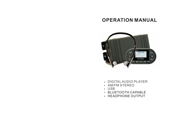
OPERATION MANUALDIGITAL AUDIO PLAYERAM/FM STEREOUSBBLUETOOTH CAPABLEHEADPHONE OUTPUTCONTENTSCONTENTS ................................................................... 1CONTROL PANEL ILLUSTRATION....................................2WIRE DIAGRAM ............................................................3INSTALLATION .............................................................. 4BASIC OPERATION ......................................................... 5RADIO OPERATION .........................................................6USB OPERATION ............................................................7iPod OPERATION..............................................................8SPECIFICATIONS ............................................................9TROUBLESHOOTING (10)TROUBLESHOOTING:WARRANTY INFORMATION:Can not read some USB devicesThe unit is not 100%compatible with all USB devices or the USB device has a special format.Try to format the USB device in FAT 16/32 standard.Can not play certain songs with specific formats that are downloaded from websitesExample:iTunes,which is in DRM (digital right management)format is not supported by the current unit while in USB mode.Unit takes about 60 seconds to recognize USB deviceIt's normal.The unit sometimes takes longer to read all the files on the USB deviceLCD cannot display the MP3 song name correctlyThe songs are in a foreign language or not in ID3 tag formatPower does not turn on (no sound)Check the wire.Check the unit fuse and if fuse is blown,simply replace with new fuse. If problem occurs again, consult the dealer.No sound output when operating the unit with amplifiers or power antenna is attachedPower antenna lead is shorted to the ground or excessive current is required for amplifiers or power antennaButton is not responsive or the LCD display is wrongThe connection pins for the front panel may be e a soft cloth to clean it's surface.If this does not fix the problem,please consult your dealer.Unit picks up engine noise Check the ground wireAfter the power is turned on, the unit power turns off immediatelyThe battery may be too low (operating voltage is 11V to 16V).If the unit still cannot turn on, please consult your dealer.Should this product require service,you may obtain specific information by contacting the dealer from whom this product was purchased.For any service related questions, please call our technical service team.Technical Support Phone Number:843-849-9037CONTROL PANEL ILLUSTRATION1.POWER ON/OFF2.FUNCTION SELECT BUTTON3.MODE BUTTON4.BAND BUTTON,Track Repeat Button5.SCAN BUTTON6.MENU7.PLAY/PAUSE8.VOLUME UP/DOWN9.RADIO tune UP/DOWN button, USB/iPod track UP/DOWN buttonSPECIFICATIONFM SpecificationAM Specification LINE OUT GENERALFrequency Range 87.5-107.9MHz Channel step 200KHz Sensitivity 10dB Signal to Noise Radio 55dbTuning European or USA Frequency Range 530-1710 Khz Channel step 10KHz Usable Sensitivity 32dBuv Signal to noise Radio 50dB Output2Volt (max)Impedance33ohmOperating temperature 032to50122Storage temperature -25-13to 85185Humidity up85%RH, non condensing Waterproof level BLACK BOX IP-66COMMANDER IP-67Voltage input 12V DC(10~14.5V allowable)Current input 10A peak Output power 4x45Impedance 4 or 8 ohms Weight 2lbs(0.75kg)Dimensions (W*H*D)Black Box (210mm*92mm*57mm)Commander (140mm*71mm*18mm)℃(℉)℃(℉)℃(℉)℃(℉).Note: Specifications and design are subject to modification without notice due to improvement.WIRING DIAGRAMFUSE REPLACEMENT:If the fuse blows,check the power connection and replace the fuse.If the fuse blows again after the replacement,there may be an internal malfunction. In this case,Warning:Only replace fuse with the same type and e of a different type or rating may cause serious damage consult your nearest repair center./safety concerns.Search functionMove cursor to SEARCH and press SEL to enter search function,the unit can search all the songs titles started with the specified word (only character 0~9 and a~z is supported).For example,if you want to search songs started with character “M”,press VOL+/-button until the character “M”displayed on LCD,and then press “SEL”button.The songs whose title starts with M will be searched and displayed on LCD,You can then press VOL+/- button to select.Note:it always takes more time for searching all the song in the USB drives especially when the USB drive size is big.iPod Operation (Additional cable required for iPod connectivity “Mil-iplug”)Connecting iPodYou may connect your iPod through an iPod port at the back of your unit,This cable can be purchased through your nearest dealer/distributor or through Playing songs in iPod1,Press MODE repeatedly until iPod is displayed on LCD,the unit will play iPod automatically.2, Press button to pause playing and press again to resume.3,Press MENU to access iPod menu,you can select between PLAYLIST,ARTIST,ALBUM,GENRE,SONGSby pressing VOL+/-button,and then press SEL to select the folder or play the songs.Whenyou are selecting between the menus,simply press MENU button to return to up one level menu simply press MENU button to go back one screen at a time.4, Press and Hold SEEK+/- button to fast forward/rewind the song playing.5, Press BD/RPT button to select iPod repeat mode.For connecting iPod, MP3 players and other portable media players.,AUX IN PORTAuto ScanIn tuner mode menu,select the Search Stations,the radio will search the15 strongest stations(FM mode)or10strongest stations(AM mode),and store them to the presets.Preset ScanIn tuner mode menu,select Preset Scan,the radio will scan all the stored stations on current band, and play for 5 second at each station.USB OperationsConnect your USB drive to the USB port at the rear of the unit.Press MODE button repeatedly until USB mode displayed on LCD,the unit will start playing the audio files in the USB drive.Listening to the music,1, Play/Pause (7)Push to pause playing in USB mode, and push again to resume play.2, SCAN (5)Press this button to listen to the first10seconds audio of each track.Press this button again to restore the player to its normal play mode.3, BD/RPT(4)Press this button while playing a desired track to play the track repeatedly. Press BD/RPT button again to return to normal play mode.4, MENU (6)There are four modes in USB menu list:FILE LIST,FOLDER LIST, RANDOM,SEARCH.Press VOL+/-button to move the cursors and Press SEL button to select.FILE LISTIn files list mode,all the audio files in the USB drive will be displayed on the LCD, press VOL+/- and SEL button to select a button to play.FOLDER LISTIn folder list mode,all the folders in the USB drive will be displayed on the LCD,press VOL+/-and SEL button to browse the audio files in the folder. Then press VOL+/-again to select a desired button,and press SEL button to play.RANDOM PLAYSimply pressing SEL to turn RANDOM PLAY ON/OFF when the cursor is moved to RANDOM mode.INSTALLATIONBest:90 facing upwardTUNER REGIONThe MM1BLACK BOX can support USA and EURO frequency,Simply press SEL button to set USA or EURO frequency.CLOCK OperationMODE button (MODE) (3)MENU (6):There are two settings in Clock setting menu:1,12hour/24hour display mode switch,press SEL to change the clock display mode2,Adjust the clock settings:the hours will blink at first,press VOL+/-to adjust the hour,and then press SEL,the minute will blink,press VOL+/-to adjust, and SEL to exit.Press to switch mode:TUNER/USB/AUX/IPOD modes.The MENU functions are different in different mode.I cannot get Manual tuning to work.Radio Operation:Listening to the radioPress MODE (3) to select the radio mode, the frequency appears on LCD.Press BD/RPT to select radio band FM AM Auto seek a station:Press “SEEK+/-”button to start a seek.Manual tuningPress and Hold “SEEK+/-”button to change to manual tuning mode.Storing a scanPress MENU,then press SEL+/-button to move cursor to SAVE CURRENT.Should you wish to save the current station,pressing the “SEL”button will add that station to a preset.Note:there are 15preset stations for FM and 12preset stations for AM.When all the presets are full,user should remove a preset before storing a new one.Moving to a presetPress MENU,then press VOL+/-button to move cursor to RECALL,and then the preset list will be displayed on LCD.Press SEL to select one of the frequencies using the VOL+/-to scroll up or down through that preset list.Automatically tuning control (SCAN)In tuner mode,press SCAN button to scan the stations;the radio will play the searched stationed for 5seconds before the next scan.Press SCAN again to stop scanning.→Basic Operations:POWER ON/OFF 1SELECT(2)&VOLUME UP/DOWN(8)Bluetooth Operations:Dimmer Settings:()Press this button to turn the unit on or offRepeatedly press SEL button to access audio settings,press VOLUME UP/DOWN to move the cursors to the settings below:BASS,TREBLE,FADER,BALANCE,EQUALIZER,LOUDNESS,SPEAKERPress “SEL”button to enter into the mentioned audio settings.Once the particular audio setting has been selected,use the “VOL”buttons to adjust up or down.Press and Hold “SEL”button for 3 seconds to enter system settings.Press Volume buttons to move up or down to access the following functions:BLUETOOTH, DIMMER,TUNER REGION, CLOCK, VERSION, RESET.Then, use the “SEL”button to access the particular function desired.The PRV BLACK BOX supports an external bluetooth module that can stream audio to your external Bluetooth headset.The headset must be paired to the stereo receiver. Let's go through this process:1)Hold Select button for 3seconds until sub menu appears.Bluetooth will be the first option that comes up.Press Select button again to enter into the Bluetooth category.When the Bluetooth is turned on,a small Bluetooth icon will be displayed at the top right corner.The icon will keep blinking until a Bluetooth headset is connected/paired.2)The screen that you are now in will enable you to activateBluetooth.The “BLUETOOTH”category must be turned on and the device must be paired through the “SEARCH DEVICES”menu.3)When in Bluetooth headset mode,one can choose to either leaveon the external speakers (if connected)or turn them off.To turn off,push the SEL button to enter into Audio settings.Then use the Volume-button until the “Speaker Mute”category is reached.Then, use the “SEL”button to mute the speakers.The MM1BLACK BOX supports 10level dimmers,press VOL+/-to move cursor to DIMMER and press SEL to enter dimmer setting menu,press VOL+/- again to set the dimmer value.。
E2K-C25ME1电容式接近传感器 说明书
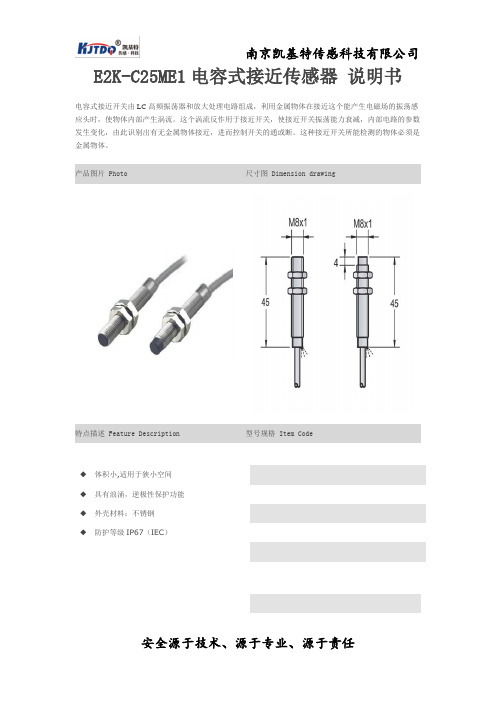
E2K-C25ME1电容式接近传感器说明书
电容式接近开关由LC高频振荡器和放大处理电路组成,利用金属物体在接近这个能产生电磁场的振荡感应头时,使物体内部产生涡流。
这个涡流反作用于接近开关,使接近开关振荡能力衰减,内部电路的参数发生变化,由此识别出有无金属物体接近,进而控制开关的通或断。
这种接近开关所能检测的物体必须是金属物体。
产品图片 Photo 尺寸图 Dimension drawing
特点描述 Feature Description型号规格 Item Code
◆体积小,适用于狭小空间
◆具有浪涌,逆极性保护功能
◆外壳材料:不锈钢
◆防护等级IP67(IEC)
电气接线图 Connection diagram规格参数 Specification
安装方式非埋入式
检测距离 4
外形规格J8*45
输出方式PNP NO
电源电压10…30VDC
开关频率1KHz
开关点偏移≤±10%
迟滞范围1…20%
重复误差≤3%
负荷电流≤100mA
残留电压≤2.5V
消耗电流≤10mA
保护回路浪涌,逆极性保护
输出指示红色LED
环境温度-25…70℃
环境湿度35-95%
防护等级IP67
外壳材料不锈钢
接线方式2米PUR电缆
无论您使用的是标准产品,还是定制的特殊产品,凯
基特都是您的最佳选择。
DigitroniK SDC25 26控制器说明书

No. CP–SS–1819ESingle Loop ControllerSDC25/26I SpecificationsHandling Precautions•The accuracy is ±0.3%FS ±1 digit, and ±0.6%FS ±1 digit for a negative area of the thermocouple.•The accuracy varies according to the range.The accuracy of the No.17 (sensor type B) is ±4.0%FS for a range of 260°C or less, ±0.4%FS for 260 to 800°C.The accuracy of the No.23 (sensor type PR40-20) is±2.5%FS for 0 to of 300°C, and ±1.5%FS for 300 to 800°C,±0.5%FS for 800 to of 1900°C.The accuracy of the No.26 (sensor type golden iron chromel) is ±1.5K.•For ranges with a decimal point, tenths are displayed on theline underneath point.Table 1 Input Types and RangesI Model Selection GuideI II III IV V VI VII VIII Example: C25TR0UA1000Gang-mountingStand-alone mountingGang-mountingStand-alone mountingI DimensionsG C25(Unit:mm)G C26G Panel cutout diagram • C25• C26Handling PrecautionsTo fasten this controller onto the panel, tighten a mounting bracket screws, and turn one more half turn when there is no play between the bracket and panel. Excessively tightening the screws may deform the controller case.Handling Precautions•When three or more units are gang-mounted horizontally, the maximum allowable ambient temperature is 40°C.•For water-proof installation, install the attached gasket and then mount the device as a stand-alone device.11100 to 240VacDigital input CurrentRelayRS-485RelayRelay (independentcontact)Current TransformerinputsCurrent VoltageThermocoupleRTDVoltage pulseVoltage pulse Current/Voltage pulseCurrentCurrent Current10)(1) Upper display:Displays PV values (present tempera-ture, etc.) or setup items.(2) Lower display:Displays SP values (set temperature,etc.) and other parameter values.When the lower display shows the SP value, the "sp" lamp lights up. When the display shows the manipulated variable (MV), the "out" lamp lights up.I Part Names and Functions(3) Mode indicatorman:Lights when MANUAL (manual mode).ev1 to ev3:Lights when event relays are ON.ot1, ot2:Lights when the control output is ON.(4) Multi-status indicator:In the combination of the lighting condition and the lighting status as a group, the priority 3 groups can be set.(5) [mode] key:The operation which has been set be-forehand can be done by pushing thekey for 1s or more.(6) [display] key:Used to change the display contentsin the operation display mode. Dis-play is returned from bank setup dis-play to operation display.(7) < , , key:Used for incrementing numeric val-ues and performing arithmetic shift operations.(8) [para] key:Switches the display.(9) [enter] keys:Used to set the setup values at thestart of change and during the change.(10) Loader connector :Connects to a personal computer byusing a dedicated cable supplied with the Smart Loader Package.<<G Connection of C25/2612C26Line filterYamatake's model No. E81446364-001(Equivalent to ZAC2205-00U Instrument Insulation transformer (100/100V)G Precautions on the use of self-tuning function The final control devices must be powered up simul-taneously with or prior to the instrument when the self-tuning function is to be used.G Precautions on wiring (2)When noise is excessiveIf a large amount of noise exists, appropriate isolation transformer and line filter are used to eliminate the effect of the noise.Additionally, do not put these lines together in the same conduit or duct.5.Inspection after wiringAfter the wiring work has been completed, always inspect and check the wiring status. Great care should be taken since incorrect wiring may cause the instru-ment to malfunction or severe personal injury.Printed in Japan. (H)1st Edition: Issued in Jan., 2004Advanced Automation Company 1-12-2 Kawana, Fujisawa Kanagawa 251-8522 Japan URL: No part of this publication may be reproduced or duplicated without the prior written permission of Y amatake Corporation.。
苯甲酸雌二醇注射液_兽用苯甲酸雌二醇注射液说明书
畜牧堂兽药说明书,更多药品请登录畜牧堂网站查询苯甲酸雌二醇注射液_兽用苯甲酸雌二醇注射液说明书本品为苯甲酸雌二醇的灭菌油溶液。
含苯甲酸雌二醇(C25H28O3)应为标示量的90.0%~110.0%。
【性状】本品为淡黄色的澄明油状液体。
【鉴别】取本品适量(约相当于苯甲酸雌二醇lmg),加无水乙醇10ml,强力振摇,置冰浴中放置使分层,取上层乙醇溶液置离心管中,离心,取上清液,作为供试品溶液;另取苯甲酸雌二醇对照品,加无水乙醇制成每1ml中含0.1mg的溶液,作为对照品溶液。
照薄层色谱法(附录23页)试验,吸取上述两种溶液各10μl,分别点于同一硅胶G薄层板上,以苯-乙醚-冰醋酸(50:30:0.5)为展开剂,展开后,晾干,喷以硫酸-无水乙醇(1:1),于105℃加热10~20分钟,取出,放冷,置紫外光灯(365nm)下检视。
供试品溶液所显主斑点的颜色和位置应与对照品溶液的主斑点相同。
【检查】应符合注射剂项下有关的各项规定(附录5页)。
【含量测定】照高效液相色谱法(附录24页)测定。
色谱条件与系统适用性试验用十八烷基硅烷键合硅腔为填充剂;甲醇-水(80:20)为流动相;检测波长为230nm。
理论板数按苯甲酸雌二醇峰计算应不低于2000。
测定法精密量取本品适量(约相当于苯甲酸雌二醇2mg),置lOOml量瓶中,加无水乙醇适量,充分振摇,待溶液澄清后,用无水乙醇稀释至刻度,摇匀,精密量取20μl注入液相色谱仪,记录色谱图;另精密称取经105℃干燥至恒重的苯甲酸雌二醇对照品适量,加无水乙醇溶液并定量稀释制成每lml中约含20μg的溶薇,同法测定。
按外标法以峰面积计算,即得。
【作用与用途】同苯甲酸雌二醇。
【用法与用量】肌内注射一次量马10~20mg 牛5~20mg 羊1~3mg 猪3~10mg 犬0.2~0.5mg【规格】(1)lml;lmg (2)lml:2mg【贮藏】遮光,密闭保存。
苯甲酸雌二醇注射液说明书兽用【兽药名称】通用名:苯甲酸雌二醇注射液商品名:英文名:Estradiol Benzoate Injection汉语拼音:Benjiasuan Ci’erchun Zhusheye【主要成分】苯甲酸雌二醇【性状】本品为淡黄色的澄明油状液体。
- 1、下载文档前请自行甄别文档内容的完整性,平台不提供额外的编辑、内容补充、找答案等附加服务。
- 2、"仅部分预览"的文档,不可在线预览部分如存在完整性等问题,可反馈申请退款(可完整预览的文档不适用该条件!)。
- 3、如文档侵犯您的权益,请联系客服反馈,我们会尽快为您处理(人工客服工作时间:9:00-18:30)。
C25砼配合比设计说明书
一、设计依据:
1、JGJ55-2000《普通混凝土配合比设计规程》的有关规定。
2、JTJ041-2000《公路桥涵施工技术规范》的有关规定。
3、GBJ146-90《粉煤灰混凝土应用技术规范》的有关规定。
二、设计要求:
1、C25砼、集中拌合砼,采用罐车运输砼。
2、混凝土坍落度要求:110~150mm。
3、试块抗压强度保证率95%。
三、原材料来源及性能参数:
1、水泥:河南登封中联水泥有限公司(P.O42.5普通硅酸盐水泥、)见附表;
2、碎石:新密市源通建材有限公司,4.75—26.5mm连续级配碎石,其性能(见附表);
3、砂:信阳,河砂、中砂,细度模数为2.8,含泥量1.3%,表观密度2.565g/cm3,堆积密度为1.484g/cm3(见附表);
4、水:井水,饮用水,冬季施工时,对拌和用水加热,搅拌时间较常温延长50%,拌和物出机温度不低于10。
C,其性能(见附表);
5、外加剂:河北省混凝土外加剂厂,聚羧酸系高效减水剂,型号:DH13型,掺量0.6%,
减水率19.4%,使用时,砂石水泥与水拌和后1-2分钟加入聚羧酸减水剂,延长拌和时间1-2分钟,其性能(见附表);
6、混合材料:I级粉煤灰,南阳鸭河口发电有限责任公司,取代水泥用量30%,其性能(见附表);
四、制作与养生的方法:
把用于砼配制的各种原材料混合并机械搅拌均匀,性能测试结果符合规范要求后,制作试件,标准养护24小时后拆模,再放入标准恒温恒湿养护室里进行养生。
五、混凝土配合比掺数的初步确定:
1、按JGJ 55-2000规范的有关规定;
2、水灰比确定:砼配制强度:f cu,0≥f cu,k+1.645σ
=25+1.645×5.0
=33.2
3、水灰比W/C = αa f ce/(f cu0+αaαb f ce)
= 0.46×42.5×1/(33.2+0.46×0.07×42.5×1)
= 0.57
4、按耐久性校核选定水灰比为0.46;
4、单位用水量的确定:按GBJ146-90附表3.2得m wo=166kg;
5、JGJ55-2000《普通混凝土配合比设计规程》4.0.2要求选取砂率βs=35%;
六、混凝土配合比材料用量确定:
1、胶凝材料用量:m co= M wo÷W/C =166÷0.46=360kg ;
2、根据GBJ146-90粉煤灰砼应用技术规范有关规定,根据确定的粉煤灰等量取代水泥量和基准混凝土水泥用量,粉煤灰混凝土中水泥量=360×(1-30%)=252kg;粉煤灰混凝土中的粉煤灰量=360-252=108kg
3、设定砼容重m cp=2410kg/m3,用下面联立方程计算砂石材料用量:
m co+m go+m so+m wo=m cp
m so /( m go+m so)×100%=βs
式中:胶凝材料用量=360kg/ m3(其中水泥=252kg;粉煤灰=108kg)
m wo=166kg/ m3 Sp=35% m cp=2410kg/m3
解联立方程得:m go=1225kg/ m3m so=659kg/ m3减水剂:2.160kg/ m3
4、每立方砼材料重量比例的初步确定:
水泥:砂:碎石:水:减水剂:粉煤灰
=252:659:1225:166:2.160:108
七、配合比试拌与调整
1、试拌:按初步配合比,取0.035m3砼的材料用量进行试拌,各材料用量为:
水泥:8.820kg ;砂:23.065kg 碎石:42.875kg ;水:5.810kg ;减水剂:0.0756kg;
粉煤灰:3.780kg 。
2、试拌后,拌合物性能实测如下:
坍落度(mm): 1)110mm ;2)120mm;平均:120mm
粘聚性:良好;泌水性:无;含砂:中;棍度:上。
3、调整:
调整情况说明:坍落度符合要求、粘聚性、保水性良好;经试配后测定砼容重为2410kg/m3;
设计密度为2410kg/m3;差值小于计算值的2.0%,故不于调整。
八、基准配合比
每立方米材料用量重量比
水泥:砂:碎石:水:减水剂:粉煤灰
=252:659:1225:166:2.160:108
= 1:2.615:4.861:0.66:0.0086:0.429
九、联立配合比的确定:
为了便于比较,增加二个较基准配合比水胶比分别增加0.03和减小0.03关联配合比。
1、混凝土最大总碱含量:≤3.0kg/m3
碱含量计算:
水泥碱含量:0.48% 粉煤灰碱含量:0 外加剂碱含量:0
水碱含量:5.1mg/L 砂碱含量:0 碎石碱含量:0
混凝土总碱含量:
252×0.48%+108×0×1/6+659×0+1225×0+166×0.0000510+2.160×0
=1.218kg/m3
2、混凝土氯离子含量不宜超过胶凝材料用量的0.15%
氯离子含量计算:
水泥氯离子含量:0.01% 砂氯离子含量:0.01% 碎石氯离子含量:0.00%
粉煤灰氯离子含量:0.05% 外加剂氯离子含量:0.03% 水氯离子含量:18.1mg/L
混凝土氯离子总含量:(252×0.01%+108×0.05%+659×0.01%+2.160×0.03%+166×0.0000181)÷360=0.041%
十一、
经试配,按照混凝土耐久性和经济适用性选定:
水泥:砂:碎石:水:减水剂:粉煤灰
=252:659:1225:166:2.160:108
= 1:2.615:4.861:0.66:0.0086:0.429
做为涵洞基础、墙身、台帽、盖板、帽石、小件预制(防护)、接桩头、系梁、截水沟、截水墙、支撑梁、急流槽、边沟跌井C25混凝土配合比。
