ansys分布载荷作用下的悬臂梁应力计算
ANSYS悬臂梁等效应力分析教程

mikeliu65
工程软件教程系列
第 9 步,施加约束。
单击打开图示对话框。
- 11 -
mikeliu65
工程软件教程系列
在弹出的对话框内输入需要的面的编号或者选择对应的面。 按照下图路径打开编号显示目录。
在弹出的对话框内勾选 AREA number。单击 ok 退出。
- 12 -
mikeliu65
单击 line 下的 set,
。弹出 element size on picked line 对话框,
单击 pick all。在弹出的对话框里,设置线段网格大小。设置每一段网格长度为 0.05m。单击 ok,完成线段长度设置。
-9-
mikeliu65
工程软件教程系列
单击 mesh tool,弹出 mesh tool 对话框。选择 HEX 单击 mesh,开始划分网格。在弹出的 mesh volumes 对话框里单击 pick all。完成网格划分。
设置完成后如下图:
-6-
mikeliu65
工程软件教程系列
第 7 步,建立体悬臂梁三维实体。
点开下图所示的路径,在弹出的窗口里输入如下参数。
-7-
mikeliu65
工程软件教程系列
点击 ok,完成三维实体创建。
-8-
mikeliu65
工程软件教程系列
第 8 步,划分网格。
单击 mesh tool,弹出 mesh tool 对话框。
-1-
mikeliu65
工程软件教程系列
第 1 步打开软件,设置文件保存路径。
打开 ansys12.0
,设置文件保存路径,在 working 内输
入保存路径。例如我的保存路径设为 F:\mikeliu65\chapter-1
悬臂梁受均布载荷的应力和变形计算
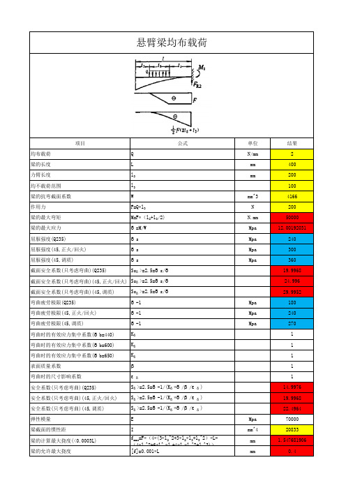
悬臂梁均布载荷项目公式单位结果均布载荷Q N/mm2梁的长度L mm400力臂长度l2mm200均不载荷范围l3100梁的抗弯截面系数W mm^34166作用力F=Q*l3N200梁的最大弯矩M=F*(l2+l3/2)N.mm50000梁的最大应力δ=M/W Mpa12.00192031屈服强度(Q235)δs Mpa240屈服强度(45,正火/回火)δs Mpa300屈服强度(45,调质)δs Mpa360截面安全系数(只考虑弯曲)(Q235)Ssδ>=2.5=δs/δ19.9968截面安全系数(只考虑弯曲)(45,正火/回火)Ssδ>=2.5=δs/δ24.996截面安全系数(只考虑弯曲)(45,调质)Ssδ>=2.5=δs/δ29.9952弯曲疲劳极限(Q235)δ-1Mpa180弯曲疲劳极限(45,正火/回火)δ-1Mpa240弯曲疲劳极限(45,调质)δ-1Mpa270弯曲时的有效应力集中系数(δb=440)Kδ1弯曲时的有效应力集中系数(δb=600)Kδ1弯曲时的有效应力集中系数(δb=650)Kδ1表面质量系数β1弯曲时的尺寸影响系数εδ1安全系数(只考虑弯曲)(Q235)Sδ>=2.5=δ-1/(Kδ*δ/β/εδ)14.9976安全系数(只考虑弯曲)(45,正火/回火)Sδ>=2.5=δ-1/(Kδ*δ/β/εδ)19.9968安全系数(只考虑弯曲)(45,调质)Sδ>=2.5=δ-1/(Kδ*δ/β/εδ)22.4964弹性模量E Mpa70000梁截面的惯性距I mm^420833mm 1.547681906梁的计算最大挠度(<0.0003L)f max=F*(4*(3*l2^2+3*l2*l3+l3^2)*L-(4*l2^2+6*l^2*l3+4*l2*l3^2+l3^3))梁的允许最大挠度[f]=0.001*L mm0.4。
ansys分布载荷作用下的悬臂梁应力计算
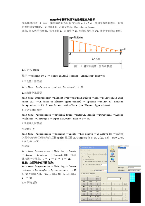
ansys 分布载荷作用下的悬臂梁应力计算分析模型如图1-1 所示, 梁的横截面为矩形 宽х高 = 1х 2 m 2. 受到分布载荷作用。
材料的弹性模量200GPa, 泊松比0.3。
习题文件名: Cantilever beam 。
注意:用实体单元离散,长度单位m, 力的单位 N ,对应应力单位 Pa ,按照平面应力处理。
1.1 进入ANSYS 程序 →ANSYSED 10.0 → input Initial jobname: Cantilever beam →OK1.2设置计算类型Main Menu: Preferences →select Structural → OK1.3选择单元类型Main Menu: Preprocessor →Element Type→Add/Edit/Delete →Add →select Solid Quad 4node 182 →OK (back to Element Types window) → Options →select K 1: Reduced integration → K3: Plane Stress →OK→Close (the Element Type window)1.4定义材料参数Main Menu: Preprocessor →Material Props →Material Models →Structural →Linear →Elastic →Isotropic →input EX:200e9,PRXY:0.3→ OK1.5生成几何模型生成特征点Main Menu: Preprocessor →Modeling →Create →Key points →In Active CS →依次输入四个点的坐标(每次输入后按Apply,最后按OK):input:1(0,0,0), 2(10,0,0), 3(10,2,0), 4(0,2,0) →OK生成面Main Menu: Preprocessor → Modeling → Create→ Areas → Arbitrary → Through KPS →依次连接四个特征点,1 → 2 → 3 → 4 → OK注意:上面两步也可简化为:Main Menu: Preprocessor → Modeling → Create→Areas → Rectangle → By two corners → WPX, WP Y 均输入0, Width 输入10, Height 输入2 → OK1.6 网格划分=0Main Menu: Preprocessor →Meshing →Mesh Tool→(Size Controls) lines: Set →拾取长边: OK→input NDIV: 50→Apply→拾取短边: →input NDIV: 10 →OK →(back to the mesh tool window)Mesh: Areas, Shape: Quad, Mapped →Mesh →Pick All (in Picking Menu) → Close( the Mesh Tool window)1.7 模型施加约束给左边施加固定约束Main Menu: Solution →Define Loads →Apply →Structural→Displacement → On lines →选左边线→OK →select 第一行: ALL DOF →第四行 VALUE 选 0: → OK给梁的上边施加线性分布载荷ANSYS 命令菜单栏: Parameters →Functions →Define/Edit→1) 在下方的下拉列表框(第三行)内选择X作为设置的变量;2) 在Result窗口中出现{X},写入所施加的载荷函数(力的单位:N):10000-1000*{X};3) File → Save 输入my_q(文件扩展名:func) →返回:Parameters →Functions →Read from file:将需要的my_q.func文件打开,任给一个参数名qq, Local coordinatesystem id for (x,y,z) 栏选0→OKUtility menu → plotctrls → Symbols → Show pres andconvect as 表框内的Face outline下拉改为 arrowsMain Menu: Solution →Define Loads →Apply →Structural →Pressure →On Lines →拾取梁的上层线→OK →在下拉列表框中选择:Existing table →Apply →选择需要的载荷参数名qq→OKsolution→load step opts→write LSFile输入文件名(注意:显示的载荷箭头应当沿着长度有长短不同)1.8 分析计算Main Menu: Solution →Solve →Current LS →OK(to close the solve Current Load Step window) →OK1.9 结果显示Main Menu: General Postproc →Plot Results →Deformed Shape… → select Def + Undeformed →OK (back to Plot Results window)→Contour Plot →Nodal Solu…→select: Stress → X Component of stress → OK1.10 退出系统ANSYS Utility Menu: File →Exit→ Save Everything→ OK。
悬臂梁变形及应力分析

基于ANSYS 10.0对悬臂梁的强度及变形分析姓名:***班级:机制0803班学号:************对悬臂梁的受力及变形分析摘要:本研究分析在ANSYS10.0平台上,采用有限元法对悬臂梁进行强度与变形分析、验证此悬臂梁设计的合理性。
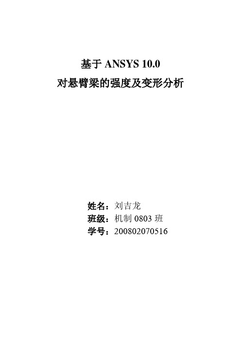
一、问题描述长度L=254 mm的方形截面的铝合金锥形杆,上端固定,下端作用有均布拉力P=68.9 Mpa,上截面的尺寸50.8×50.8 mm,下截面尺寸25.4×25.4 mm(见右图),弹性模量E=7.071×10⁴ Mpa,泊松比μ=0.3,试用确定下端最大轴向位移δ和最大轴向应力。
试将分析结果与理论解进行比较,说明有限元分析的误差。
(理论解:最大轴向位移δ=0.1238 mm)。
二、建立有限元模型:定义模型单元类型为:solid(实体)95号单元,材料常数为:弹性模量E=7.071×10⁴ Mpa,泊松比μ=0.3。
三、有限元模型图:建立有限元模型时,观察模型的形状可知,我们可以先建立模型的上下底面,再根据有上下底面形成的八个关键点(keypoints)生成线,接着生成面,生成体。
最后生成该悬臂梁的模型图,示图如下:整个模型建立好之后即可对其划分网格,划分网格时,若选择自由划分则生成的网格比较混乱,不能比较准确的模拟该梁真实的受力变形情况。
故我们选择智能划分模式,并且分别对模型的各个棱边(lines)进行均匀分割,这样可以划分出比较理想的网格,更利于我们的研究和分析。
网格划分之后的模型图为:四、加载并求解:根据该悬臂梁的受力特点,我们在其下底面(比较大的底面)上进行六个自由度的位移约束,而在其上地面上施加大小为P=68.9 Mpa均布拉力,将载荷加载好之后便可进行运算求解,求解完成之后,我们得到其位移变形图如下:Z向位移云图为:Z向应力云图为:五、结果分析及结论:由以上两张云图和一张变形图中我们可以读出,悬臂梁的最大轴向(Z向)位移和轴向(Z向)最大应力分别为:最大轴向位移为:δ=0.123746 mm 最大轴向应力为:σ=68.224 Mpa 但是,我们知道,如果所划分的网格有差异时,计算结果将会产生一定的误差,由于设计要求的最大轴向位移不能超过0.1238mm,而我们的建模计算结果已经小于此设计要求值。
悬臂梁变形及应力分析
基于ANSYS 10.0对悬臂梁的强度及变形分析姓名:刘吉龙班级:机制0803班学号:200802070516对悬臂梁的受力及变形分析摘要:本研究分析在ANSYS10.0平台上,采用有限元法对悬臂梁进行强度与变形分析、验证此悬臂梁设计的合理性。
一、问题描述长度L=254 mm的方形截面的铝合金锥形杆,上端固定,下端作用有均布拉力P=68.9 Mpa,上截面的尺寸50.8×50.8 mm,下截面尺寸25.4×25.4 mm(见右图),弹性模量E=7.071×10⁴ Mpa,泊松比μ=0.3,试用确定下端最大轴向位移δ和最大轴向应力。
试将分析结果与理论解进行比较,说明有限元分析的误差。
(理论解:最大轴向位移δ=0.1238 mm)。
二、建立有限元模型:定义模型单元类型为:solid(实体)95号单元,材料常数为:弹性模量E=7.071×10⁴ Mpa,泊松比μ=0.3。
三、有限元模型图:建立有限元模型时,观察模型的形状可知,我们可以先建立模型的上下底面,再根据有上下底面形成的八个关键点(keypoints)生成线,接着生成面,生成体。
最后生成该悬臂梁的模型图,示图如下:整个模型建立好之后即可对其划分网格,划分网格时,若选择自由划分则生成的网格比较混乱,不能比较准确的模拟该梁真实的受力变形情况。
故我们选择智能划分模式,并且分别对模型的各个棱边(lines)进行均匀分割,这样可以划分出比较理想的网格,更利于我们的研究和分析。
网格划分之后的模型图为:四、加载并求解:根据该悬臂梁的受力特点,我们在其下底面(比较大的底面)上进行六个自由度的位移约束,而在其上地面上施加大小为P=68.9 Mpa均布拉力,将载荷加载好之后便可进行运算求解,求解完成之后,我们得到其位移变形图如下:Z向位移云图为:Z向应力云图为:五、结果分析及结论:由以上两张云图和一张变形图中我们可以读出,悬臂梁的最大轴向(Z向)位移和轴向(Z向)最大应力分别为:最大轴向位移为:δ=0.123746 mm 最大轴向应力为:σ=68.224 Mpa 但是,我们知道,如果所划分的网格有差异时,计算结果将会产生一定的误差,由于设计要求的最大轴向位移不能超过0.1238mm,而我们的建模计算结果已经小于此设计要求值。
有限元分析及应用报告-利用ANSYS软件分析带孔悬臂梁
有限元分析及应用报告题目:利用ANSY软件分析带孔悬臂梁姓名:xxx学号:xxx班级:机械xxx学院: 机械学院指导老师:xxx二零一五年一月问题概述图示为一隧道断面,其内受均布水压力q,外受土壤均布压力p;试采用不同单元计算断面内的位移及应力,并分别分析q=0或p=0时的位移和应力分布情况。
(材料为钢,隧道几何尺寸和压力大小自行确定)本例假定内圆半径为1m,外圆半径为2m,外受均布压力p=10000pa ,内受均布压力为q=20000pa 。
问题分析由题目可知,隧道的的长度尺寸远远大于截面尺寸,并且压力在长度方向上均匀分布,因此本问题可以看作为平面应变问题。
由于在一个截面内,压力沿截面四周均匀分布,且截面是对称的圆环,所以可以只取截面1/4进行有限元建模分析,这样不仅简化了建模分析过程,也能保证得到精确的结果。
由以上分析,可以选取单元类型plane42进行有限元分析,在option中选择K3 为plane strain。
三.有限元建模1.设置计算类型由问题分析可知本问题属于平面静应力问题,所以选择preferences 为structure 。
2.单元类型选定选取平面四节点常应变单元plane42,来计算分析隧道截面的位移和应力。
由于此问题为平面应变问题,在设置element type的K3时将其设置为plane strain。
3.材料参数隧道的材料为钢,则其材料参数:弹性模量E=2.1e11,泊松比(T =0.34.几何建模按照题目所给尺寸利用ansys的modeling依次建立keypoint :1(0,0),2(1,0),3(2,0),4(0,2),5(0,1) , create LINES 依次连接keypoint 2、3和4、5即可创建两条直线,使用create article 的By cent & radius 创建两条圆弧。
create AREAS依次选择四条线即建立了所需的1/4截面。
ansys workbench例题
Ansys Workbench是一款广泛应用于工程领域的有限元分析软件,可以用于解决各种结构力学、流体动力学、电磁场等问题。
本文将以Ansys Workbench为例,介绍一个结构力学的例题,并详细讲解解题过程。
1. 问题描述假设有一个悬臂梁,在梁的自由端施加一个集中力,要求计算梁的应力分布和挠度。
2. 建模打开Ansys Workbench软件,新建一个静力学分析项目。
在几何模型中,画出悬臂梁的截面,并确定梁的长度、宽度和厚度。
在材料属性中,选择梁的材料,并输入对应的弹性模量和泊松比。
在约束条件中,将梁的支座固定,模拟悬臂梁的真实工况。
在外部荷载中,施加一个与梁垂直的集中力,确定力的大小和作用位置。
3. 网格划分在建模结束后,需要对悬臂梁进行网格划分。
在Ansys Workbench 中,可以选择合适的网格划分方式和密度,以保证计算结果的准确性和计算效率。
通常情况下,悬臂梁的截面可以采用正交结构网格划分,梁的长度方向可以采用梁单元网格划分。
4. 设置分析类型在网格划分完成后,需要设置分析类型为结构静力学。
在分析类型中,可以选择加载和约束条件,在求解器中,可以选择计算所需的结果类型,如应力、应变、位移等。
5. 求解和结果分析完成以上步骤后,可以提交计算任务进行求解。
Ansys Workbench软件会自动进行计算,并在计算完成后给出计算结果。
在结果分析中,可以查看悬臂梁的应力分布图和挠度图,进一步分析梁的受力情况和变形情况。
6. 参数化分析除了单一工况下的分析,Ansys Workbench还可以进行参数化分析。
用户可以改变材料属性、外部加载、几何尺寸等参数,快速地进行批量计算和结果对比分析,以得到最优的设计方案。
7. 结论通过Ansys Workbench对悬臂梁的结构分析,可以得到悬臂梁在外部加载下的应力分布和挠度情况,为工程设计和优化提供重要参考。
Ansys Workbench还具有丰富的后处理功能,可以绘制出直观的分析结果图,帮助工程师和研究人员更好地理解和使用分析结果。
ANSYS悬臂梁的自由端受力的有限元计算[1]
![ANSYS悬臂梁的自由端受力的有限元计算[1]](https://img.taocdn.com/s3/m/6ed4c5c1da38376baf1faec4.png)
悬臂梁自由端受力的有限元计算一、计算目的1、掌握ANSYS软件的基本几何形体构造、网格划分、边界条件施加等方法。
2、熟悉有限元建模、求解及结果分析步骤和方法。
3、利用ANSYS软件对梁结构进行有限元计算。
4、梁的变形、挠曲线等情况的分析。
5、一维梁单元,二维壳单元,三维实体单元对计算结果的影响。
6、载荷施加在不同的节点上对结果的影响。
二、计算设备PC,ANSYS软件(版本为11.0)三、计算内容悬臂梁受力模型如上图所示,一段长100[mm]的梁,一端固定,另一段受到平行于梁截面的集中力F的作用,F=100[N]。
梁的截面为正方形,边长为10[mm]。
梁所用的材料:弹性模量E=2.0 105[MPa],泊松比0.3。
四、计算步骤(以梁单元为例)1、分析问题。
分析该物理模型可知,截面边长/梁长度=0.1是一个较小的值,我们可以用梁单元来分析这样的模型。
当然,建立合适的壳单元模型和实体单元模型也是可以的。
故拟采用这三种不同的方式建立模型。
以下主要阐述采用梁单元的模型的计算步骤。
2、建立有限元模型。
a)创建工作文件夹并添加标题;在个人的工作目录下创建一个文件夹,命名为beam,用于保存分析过程中生成的各种文件。
启动ANSYS后,使用菜单“File”——“Change Directory…”将工作目录指向beam 文件夹;使用/FILNAME,BEAM命令将文件名改为BEAM,这样分析过程中生成的文件均以BEAM为前缀。
偏好设定为结构分析,操作如下:GUI: Main Menu > Preferences > Structuralb)选择单元;进入单元类型库,操作如下:GUI: Main Menu > Preprocessor > Element Type > Add/Edit/Delete > Add…对话框左侧选择Beam选项,在右侧列表中选择2D elastic 3选项,然后单击OK按钮。
材料力学悬臂梁应力计算
材料力学悬臂梁应力计算材料力学是一门研究材料在力学作用下的力学性能的学科。
悬臂梁是材料力学中一个重要的力学结构,其应力计算是材料力学研究的重点内容之一悬臂梁是一根一端固定,另一端自由悬挂的梁,在实际工程中广泛应用于建筑、桥梁、汽车和航空等领域。
悬臂梁的应力计算是设计和分析该结构强度和稳定性的关键步骤。
为了进行悬臂梁的应力计算,首先需要了解材料的力学性质。
材料力学性质包括弹性模量、屈服强度、断裂韧度等。
这些性质描述了材料在力学作用下的变形、强度和断裂性能。
悬臂梁的应力计算可以分为静力学分析和弹性力学分析两个步骤。
在静力学分析中,根据悬臂梁的受力情况,可以得到悬臂梁上的切线力和弯矩。
在弹性力学分析中,可以根据悬臂梁的几何形状和材料性质计算出悬臂梁上的应力。
常见的应力计算公式包括悬臂梁的弯曲应力公式和剪切应力公式。
对于悬臂梁的弯曲应力计算,可以使用悬臂梁的弯曲方程进行计算。
弯曲方程描述了悬臂梁上的弯曲曲线和应力分布,可以根据悬臂梁的载荷和几何形状计算出悬臂梁上的最大应力。
悬臂梁的弯曲方程可以通过一些经典方法求解,例如Euler-Bernoulli悬臂梁理论和Timoshenko悬臂梁理论。
对于悬臂梁的剪切应力计算,可以使用剪切力的变化率进行计算。
剪切力是悬臂梁上的横向力,可以通过静力学分析得到。
剪切应力是悬臂梁上截面上垂直剪切力作用下的应力,可以通过剪切力和悬臂梁的截面面积计算得到。
除了弯曲应力和剪切应力,还需要考虑其他引起应力的因素,例如温度变化和预应力等。
温度变化会引起悬臂梁的热应力,而预应力可能会改变悬臂梁的应力分布。
总结起来,悬臂梁的应力计算是材料力学中一个重要的研究内容。
它可以通过静力学分析和弹性力学分析来计算悬臂梁上的应力。
悬臂梁的应力计算不仅可以用于设计和分析悬臂梁的结构强度和稳定性,还可以用于预测悬臂梁在使用过程中的变形和破坏情况。
因此,悬臂梁的应力计算对于材料力学的研究和实际工程应用有着重要的意义。
ANSYS Example06悬臂梁优化算例 (ANSYS)
06 悬臂梁优化算例(ANSYS)在实际工程中,经常遇到需要对结构构件进行截面优化,以充分利用材料并节省造价。
ANSYS软件提供了一些常用的结构优化功能,本算例将以一个受均布荷载的平面悬臂梁为例,介绍实用ANSYS软件对构件进行优化。
知识要点:(1)输出命令流文件(2)Element Table的使用(3)结果的求和,排序(4)设计变量,状态变量,目标变量(5)优化算法(1)首先用ANSYS建立有限元模型,先输入以下控制参数:P=1e6 ! 作用在悬臂梁上的局部荷载L=10 ! 悬臂梁长度T1=1 ! 悬臂梁固定端截面高度T2=1 ! 悬臂梁中点截面高度T3=1 ! 悬臂梁自由端截面高度(2)进入ANSYS主菜单Preprocessor->Element Type->Add/Edit/Delete,添加单元类型为Plane 82(3)在ANSYS主菜单Materials Props->Material Models中添加钢材材料属性:Structural->Linear->Elastic->Isotropic,输入弹性模量为200E3,泊松比为0.3(1)下面建立悬臂梁的模型,首先建立关键点信息,在ANSYS主菜单Preprocessor->Modeling->Create->Keypoints->In Active CS,依次输入以下关键点:(4)选择ANSYS主菜单,依次连接关键点1-2,2-3,3-6,6-5,5-4,4-1,5-2(5)选择ANSYS主菜单Preprocessor->Modeling->Create->Areas->Aribitrary->By Lines,依次点选直线1,7,5,6和2,3,4,7,生成面模型如图(6)进入ANSYS主菜单Preprocessor->Meshing ->Size Cntrls ->ManualSize ->Global->Size,设定单元的最大尺寸为L/50(7)进入ANSYS主菜单Preprocessor->Meshing ->Mesh->Areas->Free,对生成的面进行网格划分(8)完成建模后开始添加边界条件,首先进入ANSYS主菜单Solution->DefineLoads->Apply->Structural->Displacement->On Lines,选中直线6,选择约束所有位移(9)接着进入ANSYS主菜单Solution->Define Loads->Apply->Structural->On Lines,选择直线1和直线2,输入压力大小为P(10)下面进行求解,进入ANSYS主菜单Solution->Solve->Current LS,求解当前工况(11)然后进入后处理进行结果整理,首先进入ANSYS主菜单General Postproc->ListResults->Sorted Listing->Sort Nodes,选择对所有节点的von Mises应力进行排序。
ansys工字悬臂梁受力分析

• 3) 选择MainMenu→Solution→Define Loads→Apply→Structural→Force/Moment→On Keypoints 命令,出现Apply F/M on KPs拾取菜单。 • 4)用鼠标在ANSYS显示窗口选取编号为2关键点,单击【OK】按钮,出现Apply F/M on KPs对 话框,在Lab Direction of force/mom下拉菜单中选择FY,在Apply as下拉菜单中选择Constant value,在VALUE Force/moment value 输入栏中输入-8000,如图所示。 命令流:FK,2,FY,-8000
命令流:R,1,0.006655,0.00019,0.32
⒊ 定义材料性能参数
• 1)选择MainMenu→Preprocessor→MaterialProps→Material Models命令,出现Define Material Model Behavior对话框。 • 2)在Material Models Available 输入栏中选择Structural→Linear→Elastic→Isotropic命令,出现 Linear Isotropic Properties Mater... 对话框,在Linear Isotropic Material Properties for Material Number 1 输入框中,选其中的EX输入栏输入2.2e11,在PRXY输入栏输入0.3,如下图所示,单击【 OK】按钮关闭该对话框。
• 4)选择Utility Menu→PlotCtrls→Numbering命令,出现Plot Numbering Controls对话框 ,选中KP Keypoint numbers和LINE Line numbers 选项,使其状态由Off变为On,其余选项 采用默认设置,单击【OK】按钮关闭该对话框。 命令流:/PNUM,KP,1 /PNUM,LINE,1
基于ANSYS的悬臂梁剪力与弯矩图分析(含理论计算)
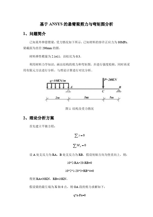
基于ANSYS的悬臂梁剪力与弯矩图分析1、问题简介已知某外伸悬臂梁,受力情况如下所示,已知材料的容许正应力为80MPa。
梁截面为直径200mm的圆。
材料弹性模量为2.1e11,泊松比为0.3。
利用材料力学知识,画出结构的剪力和弯矩图,并进行强度校核,同时再采用有限元方法进行分析,与理论计算进行对比分析。
图1 结构及受力情况2、理论分析方案首先建立平衡方程:∑=0y∑A M=设A处支反力为RA,B处支反力为RB,假设初始方向为竖直向上,则:10*2-RA+20-RB=010*2*1-20*3+RB*4=0得到RA=30KN,RB=10KN。
假设梁的最左端为X轴0点,则OA段的剪力求解如下:q*x-Fx=0得到Fx=10*x,其中0<x<2,且方向向上在AC段,则2<x<5,剪力求解方程如下:10*2-RA+Fx=0得到:Fx=10KN,且方向向下。
在CB段,其中5<x<6,剪力求解方程如下:10*2-RA+20-FX=0得到FX=10KN,其中方向向上。
由上述计算可得剪力图如下所示,其中正好表示方向向上。
图2 剪力图假设梁的最左端为X轴0点,则弯矩图的求解过程如下所示:OA段:10*x*x/2-Mx=0得到Mx=5*x^2,其中方向为顺时针。
AC 段:10*2*(1+x)-RA*x-Mx=0得到:Mx==20-10xCB段:Mx=RB*(6-x)得到MX=60-10x由上述计算可知弯矩图如下所示,图3 弯矩图由图3可知,梁的最大正弯矩为Mc=10KN*m最大负弯矩为Ma=20KN*m 。
其中弯曲应力计算公式如下所示:3max max max max max 32d M W M I y M Z πσ=== 所以如上所示梁结构的最大弯曲应力发生在截面A 处,按照如上公式计算,知最大应力为25.478MPa ,材料许用正应力为80MPa ,此时安全系数为3.14,材料满足强度要求。
材料力学悬臂梁应力计算
材料力学悬臂梁应力计算材料力学悬臂梁应力计算悬臂梁是由一端固定支撑,另一端向外悬挂的结构形式。
在工程实践中,我们经常会遇到需要计算悬臂梁上的应力情况的问题。
悬臂梁的应力分析是材料力学中一个重要而有挑战性的问题,它在工程设计和结构安全性评估方面起着重要的作用。
首先,在进行悬臂梁应力计算之前,我们需要了解悬臂梁的几何参数和受力情况。
几何参数包括悬臂梁的长度、截面形状以及截面尺寸等。
受力情况包括悬臂梁上的外载荷、支撑约束和边界条件等。
当我们确定了悬臂梁的几何参数和受力情况后,接下来可以通过应力计算公式来计算悬臂梁上的应力分布。
悬臂梁的应力计算一般可以采用弯曲应力理论或者兼顾弯曲和剪切应力的复合应力理论。
根据这些理论,我们可以得到悬臂梁上的弯曲应力和剪切应力的表达式。
弯曲应力是指在悬臂梁上由外载荷引起的弯曲变形而产生的应力。
它与悬臂梁上截面的几何形状和外载荷之间有着密切的关系。
我们可以通过弯矩-曲率关系来计算悬臂梁上的弯曲应力。
弯矩-曲率关系描述了悬臂梁在受到外力作用下的曲率与弯矩之间的关系。
剪切应力是指在悬臂梁上由外载荷引起的剪切力而产生的应力。
悬臂梁的剪切应力分布是非常复杂的,它与悬臂梁上的截面形状和剪切力分布有着密切的关系。
我们可以通过横截面的剪力和惯性矩来计算悬臂梁上的剪切应力。
在进行悬臂梁应力计算时,我们需要注意一些重要的问题。
首先,应该保证所选用的应力计算理论与实际情况相吻合。
不同的应力计算理论适用于不同的受力情况。
其次,应力计算中的各个参数和变量应在计算过程中准确无误地输入。
错误的输入可能导致计算结果的不准确性。
最后,需要对计算结果进行合理的评估和分析,以确定悬臂梁的结构安全性。
悬臂梁应力计算是材料力学中一个复杂而重要的问题。
通过合理地选择应力计算理论和准确地输入参数,我们可以得到悬臂梁上的应力分布情况。
这对于工程设计和结构安全性评估具有重要的指导意义。
希望通过深入学习和研究悬臂梁应力计算问题,我们能够更好地应对工程实践中的挑战,为工程结构的安全运行提供可靠的保障。
悬臂梁的ANSYS典型分析过程
2 、定义参数 Utility Menu>Parameters>Scalar Parameters 文本框中输入“L=2”, “H=0.1”、 “B=0.05”、 “XSECT=H*B” “INERTIAZ=(B*H*3)/12”
3 、定义单元类型和梁的截面尺寸 Main Menu>Preprocessor>Element Type>Add/Edit/Delete 选择“Structural Beam”和“2D elastic 3”选项。
悬臂梁的ANSYS典型分析过程
5
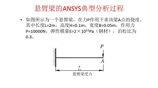
• 如图所示为一个悬臂梁,在力P作用下求该梁A点的挠度。 其中长度L=2m,高度H=0.1m,宽度B=0.05m,作用力 P=10000N,弹性模量E=2×10¹¹Pa(钢材),泊松比为 0.3。
P
A
4
悬臂梁受力
1 、定义工作文件名 Utility Menu>File>Change Jobname :“Beam”, 选择【New log and error files】寸
Main Menu>Preprocessor>Real Constants>Add/Edit/Delete 选择“Type l BEAM3”选项。弹 出【Real constants for BEAM3】对话框。输入几何特性 “xsect”、“inertiaz”和 “h”,单击“OK”按钮。
10、显示变形结果 Main Menu>General Postproc>Plot Results>Deformed Shape 弹 出 【Plot Deformed Shape】 对 话 框 。 选 择 “Def+undeformed”,生成结果如图1-19所示。
【干货】基于ANSYS的悬臂梁模态分析
【干货】基于ANSYS的悬臂梁模态分析1、连续系统的振动实际的振动系统都是连续体,它们具有连续分布的质量与弹性,因而又称连续系统或分布参数系统。
由于确定连续体上无数质点的位置需要无限多个坐标,因此连续体是具有无限多自由度的系统。
连续体的振动要用时间和空间坐标的函数来描述,其运动方程不再像有限多自由度系统那样是二阶常微分方程组,它是偏微分方程。
在物理本质上,连续体系统和多自由度系统没有什么差别,连续体振动的基本概念与分析方法与有限多自由度系统是完全类似的。
2、说明(1) 本章讨论的连续体都假定为线性弹性体,即在弹性范围内服从虎克定律。
(2) 材料均匀连续;各向同性。
(3) 振动满足微振动的前提。
3、梁的弯曲振动动力学方程考虑细长梁的横向弯曲振动梁参数:ρ单位体积梁的质量E弹性模量I截面对中性轴的惯性距S 梁横截面积外部力:m(x,t): 单位长度梁上分布的外力矩f(x,t): 单位长度梁上分布的外力假设:(1) 梁各截面的中心惯性轴在同一平面xoy内(2) 外载荷作用在该平面内(3) 梁在该平面作横向振动(微振)(4) 这时梁的主要变形是弯曲变形(5) 在低频振动时可以忽略剪切变形以及截面绕中性轴转动惯量的影响伯努利-欧拉梁(Bernoulli-Euler Beam)令:y(x,t):距原点x处的截面在t时刻的横向位移微段受力分析力平衡方程:4、悬臂梁的固有频率和模态函数5、两端固定杆的纵向模态分析问题描述:一悬臂梁截面为矩形,如图1所示,几何尺寸及材料特性如下,分析其前三阶固有频率及振型。
GUI操作如下:一、菜单建模分析过程第一步,清除内存准备分析1) 清除内存:选择菜单Utility Menu>File>Clear& Start New,单击OK按钮。
2) 更换工作文件名:选择菜单Utility Menu>File>ChangeJobname,输入vibration of cantilever,单击OK按钮。
三角形悬臂梁应力分析
三角形悬臂梁应力分析摘要:在有限元分析软件ANSYS12.0平台上建立三角形悬臂梁的力学模型,添加约束和载荷,计算出应力分布,并与理论计算值相比较。
⒈ 引言目前,ANSYS 软件具有其强大的功能已经被广泛的应用于机械,化工,土木,交通等各个领域。
应用ANSYS 分析,可以大大减少人力物力的投入,而且可靠性高,对于三角形悬臂梁分析其应力和变形情况,分析方法和结论可作为这类设计的参考。
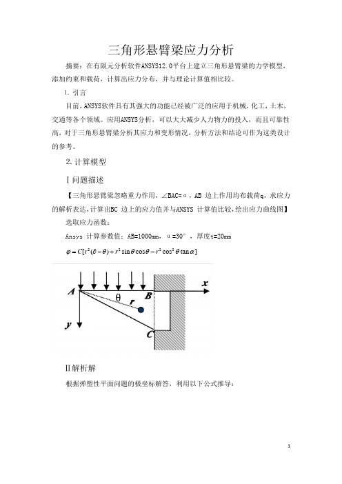
⒉ 计算模型 Ⅰ问题描述【三角形悬臂梁忽略重力作用,∠BAC=α,AB 边上作用均布载荷q ,求应力的解析表达,计算出BC 边上的应力值并与ANSYS 计算值比较,绘出应力曲线图】选取应力函数:Ansys 计算参数值:AB=1000mm ,α=30°,厚度t=20mm2222[()sin cos cos tan ]C r r r ϕθθθθα=∂-+-Ⅱ解析解根据弹塑性平面问题的极坐标解答,利用以下公式推导:222222211111()r r r r r rr r r r r θθϕϕσθϕσϕϕϕτθθθ∂∂=+∂∂∂=∂∂∂∂∂=-=-∂∂∂∂∂以及2222cos sin 2sin cos sin cos 2sin cos x r r y r r θθθθσσθσθτθθσσθσθτθθ=+-=++已知2222[()sin cos cos tan ]C r r r ϕθθθθα=∂-+-, 故有以下式子成立:22222222222[2()2sin cos 2cos tan ][2()2sin cos 2cos tan ][cos 2sin 2tan ][2sin 22cos 2tan ]C r r r r C rC r r r C r r ϕαθθθθαϕαθθθθαϕθθαθϕθθαθ∂=-+-∂∂=-+-∂∂=-++∂∂=-+∂所以,22222222211[2()sin 22cos tan 2cos 2tan ][2()sin 22cos tan ]111()[1cos 2sin 2tan ]r r C r r r C rC r r r r r θθϕϕσαθθθαθαθϕσαθθθαϕϕϕτθθαθθθ∂∂=+=---+∂∂∂==-+-∂∂∂∂∂=-=-=--∂∂∂∂∂因此,222222222224cos sin 2sin cos [2()2sin 2cos 2cos tan 2cos cos 2tan sin 2cos 2sin 2tan ]sin cos 2sin cos [2()2cos sin 2cos 2sin 2tan 2tan sin cos 3tan cos ]x r r y r r C C θθθθσσθσθτθθαθθθθαθθαθθθασσθσθτθθαθθθθθααθθαθ=+-=---+++=++=-+-++- 由边界0()/y y q t σ==-,即当0θ=时,/y q t σ=-;带入y σ的表达式中可得:2(tan )qC t αα=-将C 带入x σ表达式中得:22222222[2()2sin 2cos 2cos tan 2cos cos 2tan sin 2cos 2sin 2tan ][2()2sin 2cos 2cos tan 2(tan )2cos cos 2tan sin 2cos 2sin 2tan ]x C qt σαθθθθαθθαθθθααθθθθαααθθαθθθα=---+++=----+++Ⅲ Ansys 计算问题详细说明:取AB=1000mm ,30α= ,厚度t=20mm ,50/q N mm =-。
悬臂梁受集中载荷的应力变形计算
悬臂梁受集中载荷的应力变形计算悬臂梁是一种常见的结构,在工程中应用广泛。
在设计和分析悬臂梁时,经常需要计算受集中载荷作用下的应力和变形。
本文将对悬臂梁受集中载荷的应力和变形计算进行详细阐述。
一、悬臂梁受集中载荷的应力计算1.弯曲应力计算当悬臂梁受到集中荷载作用时,会产生弯曲应力。
弯曲应力是由于载荷作用引起梁的弯曲变形而产生的。
计算弯曲应力可使用弯曲应力公式:σ=(M*y)/I其中,σ为弯曲应力,M为弯矩,y为弦纤维上离中轴线的距离,I 为截面转动惯量。
在悬臂梁上的集中荷载作用下,弯矩可通过以下公式计算:M=F*L其中,M为弯矩,F为集中荷载,L为悬臂梁的长度。
对于矩形截面的悬臂梁,截面转动惯量I可通过以下公式计算:I=(b*h^3)/12其中,I为截面转动惯量,b为矩形截面的宽度,h为矩形截面的高度。
2.剪切应力计算除了弯曲应力外,悬臂梁还会受到剪切应力的作用。
剪切应力是指梁截面内部不同层次之间的相对滑动所产生的应力。
计算剪切应力可使用剪切应力公式:τ=(V*Q)/(b*I)其中,τ为剪切应力,V为剪力,Q为梁截面的截面模量,b为截面的宽度,I为截面转动惯量。
悬臂梁上的剪力可通过以下公式计算:V=F其中,V为剪力,F为集中荷载。
悬臂梁的截面模量Q可通过以下公式计算:Q=(b*h^2)/6其中,Q为截面模量,b为截面的宽度,h为截面的高度。
二、悬臂梁受集中载荷的变形计算1.弯曲变形计算悬臂梁受到集中载荷作用时,会产生弯曲变形。
弯曲变形是指悬臂梁由于受到集中载荷作用发生的弯曲现象。
计算弯曲变形可使用弯曲变形公式:δ=(M*L^2)/(2*E*I)其中,δ为弯曲变形,M为弯矩,L为悬臂梁的长度,E为弹性模量,I为截面转动惯量。
2.剪切变形计算悬臂梁除了弯曲变形外,还会受到剪切变形的作用。
剪切变形是指梁截面内部不同层次之间的相对滑动所产生的变形。
计算剪切变形可使用剪切变形公式:θ=(V*L)/(G*Q)其中,θ为剪切变形,V为剪力,L为悬臂梁的长度,G为剪切模量,Q为截面模量。
[精品]悬臂梁在均布荷载下的应力状态
![[精品]悬臂梁在均布荷载下的应力状态](https://img.taocdn.com/s3/m/51591f2e366baf1ffc4ffe4733687e21af45fffd.png)
悬臂梁在均布荷载下的应力状况摘要:悬臂梁在现实生活中很常见,对于悬臂梁的分析采用弹性力学里的应力边界条件和平微分方程和相容方程进行求解计算分析,再结合材料力学的知识进行分析,深入系统的了解悬臂梁的手里特点。
关键词:静定梁、悬臂梁、弹性力学、材料力学、受力特点现实生活中的房屋建筑中,存在很多的悬臂梁结构,身边的例子很多,例如体育场的看台,城市里房屋的阳台,农村房屋中很多都有屋檐,而其都是靠悬臂梁的支撑才能结合上面的附属物件构成。
现在我们就对悬臂梁的应力情况分别采用弹性力学和材料力学的相关知识进行分析如图所示梁受荷载作用,求解其应力1、弹性力学求解 解:本题是按应力求解的。
基本公式xC xy hq C y C y hqy y x h q xy y x 123213332362)46(+=+--=--=τσσ 1、在应力法中,应力分量在单连体中必须满足:y qlx⎪⎪⎭⎫ ⎝⎛-20222qh ql l 202qh qoh /2 h /2 (l >>h ,δ=1)(1)平衡微分方程;00=+∂∂+∂∂=+∂∂+∂∂y xyy x yxx f x y f yx τστσ(2)相容方程 ()02=+∇y x σσ;(3)应力边界条件(在σs s =上)。
将应力分量代入平衡微分方程和相容方程,两者都能满足。
2、校核边界条件(1)在主要边界上04602123=⎪⎪⎭⎫ ⎝⎛+⋅=±=C h h q x hy xy ,即时,τ,由此得hqC 231-= q C hC h h q q h y y -=++⎪⎪⎭⎫ ⎝⎛--=-=2133282,2即-时,σ,由此得22q C -= 0==y hhy σ时,,将C 1、C 2代入后满足。
将C 1、C 2代入式(a ),得到应力公式:()⎪⎪⎭⎫ ⎝⎛-=⎪⎪⎭⎫⎝⎛+--=--=1423223212322223223h y h qx h y h y q y x hqyxyy x τσσ (b )(2)再将式(b )代入次要边界条件00==xy x τ时,334hy q x =σ,其主矢量为)(022==-⎰dy x hh x σ而主矩为20)(2220qh ydy hh x x =⎰-=σx =l 时,,其主矢量为; (2分))46(323y y l hqx --=σql dy hh x xy -=⎰-=220)(τ)14(2322-=h y h ql xyτ,其主矢量为0, (1分)而主矩为)202()(2222qh ql ydy lx hh x --==-⎰σ由此可见,在次要边界上的积分条件均能满足。
ansys静力学应力仿真公式
ansys静力学应力仿真公式ansys静力学应力仿真公式本文将列举一些与”ansys静力学应力仿真公式”相关的公式,并给出相应的解释和示例。
公式1:应力公式应力(Stress)定义为单位面积上的力的作用,可以使用以下公式计算:Stress = Force / Area其中,力(Force)是施加在物体上的力,面积(Area)是力的作用区域的面积。
示例:假设一个力为100 N的力施加在一个面积为5平方米的物体上,通过应力公式计算可以得到:Stress = 100 N / 5 m² = 20 N/m²因此,这个物体上的应力为20 N/m²。
公式2:杨氏模量杨氏模量(Young’s Modulus)用于描述材料在受力时的变形程度,公式如下:Young's Modulus = Stress / Strain其中,应力(Stress)是物体所受的力除以物体的横截面积,变形(Strain)是物体长度的变化与初始长度之比。
示例:假设一个物体受到的应力为100 N/m²,而变形为,通过杨氏模量公式计算可以得到:Young's Modulus = 100 N/m² / = 10000 N/m²因此,这个物体的杨氏模量为10000 N/m²。
公式3:梁的弯曲应力对于梁的弯曲应力(Bending Stress),可以使用以下公式计算:Bending Stress = (M * c) / I其中,M是梁上的弯矩,c是最大距离,I是惯性矩。
示例:假设一个梁上的弯矩为100 Nm,最大距离为 m,惯性矩为 m⁴,通过弯曲应力公式计算可以得到:Bending Stress = (100 Nm * m) / m⁴ = 50000 N/m²因此,这个梁上的弯曲应力为50000 N/m²。
公式4:轴的剪切应力对于轴的剪切应力(Shear Stress),可以使用以下公式计算:Shear Stress = (V * Q) / (I * b)其中,V是剪力,Q是截面的形心位置,I是惯性矩,b是截面的宽度。
- 1、下载文档前请自行甄别文档内容的完整性,平台不提供额外的编辑、内容补充、找答案等附加服务。
- 2、"仅部分预览"的文档,不可在线预览部分如存在完整性等问题,可反馈申请退款(可完整预览的文档不适用该条件!)。
- 3、如文档侵犯您的权益,请联系客服反馈,我们会尽快为您处理(人工客服工作时间:9:00-18:30)。
ansys 分布载荷作用下的悬臂梁应力计算
分析模型如图1-1 所示, 梁的横截面为矩形 宽х高 = 1х 2 m 2
. 受到分布载荷作用。
材料的弹性模量200GPa, 泊松比0.3。
习题文件名: Cantilever beam 。
注意:用实体单元离散,长度单位m, 力的单位 N ,对应应力单位 Pa ,按照平面应力处理。
1.1 进入ANSYS 程序 →ANSYSED 10.0 → input Initial jobname: Cantilever beam →OK
1.2设置计算类型
Main Menu: Preferences →select Structural → OK
1.3选择单元类型
Main Menu: Preprocessor →Element Type→Add/Edit/Delete →Add →select Solid Quad 4node 182 →OK (back to Element Types window) → Options →select K 1: Reduced integration → K3: Plane Stress →OK→Close (the Element Type window)
1.4定义材料参数
Main Menu: Preprocessor →Material Props →Material Models →Structural →Linear →Elastic →Isotropic →input EX:200e9,PRXY:0.3→ OK
1.5生成几何模型
生成特征点
Main Menu: Preprocessor →Modeling →Create →Key points →In Active CS →依次输入四个点的坐标(每次输入后按Apply,最后按OK):input:1(0,0,0), 2(10,0,0), 3(10,2,0), 4(0,2,0) →OK
生成面
Main Menu: Preprocessor → Modeling → Create
→ Areas → Arbitrary → Through KPS →依次
连接四个特征点,1 → 2 → 3 → 4 → OK
注意:上面两步也可简化为:
Main Menu: Preprocessor → Modeling → Create
→Areas → Rectangle → By two corners → WP
X, WP Y 均输入0, Width 输入10, Height 输入
2 → OK
1.6 网格划分
=0
Main Menu: Preprocessor →Meshing →Mesh Tool→(Size Controls) lines: Set →拾取长边: OK→input NDIV: 50→Apply→拾取短边: →input NDIV: 10 →OK →(back to the mesh tool window)Mesh: Areas, Shape: Quad, Mapped →Mesh →Pick All (in Picking Menu) → Close( the Mesh Tool window)
1.7 模型施加约束
给左边施加固定约束
Main Menu: Solution →Define Loads →Apply →Structural
→Displacement → On lines →选左边线→OK →select 第
一行: ALL DOF →第四行 VALUE 选 0: → OK
给梁的上边施加线性分布载荷
ANSYS 命令菜单栏: Parameters →Functions →Define/Edit
→
1) 在下方的下拉列表框(第三行)内选择X作为设置的变量;
2) 在Result窗口中出现{X},写入所施加的载荷函数(力的单
位:N):10000-1000*{X};
3) File → Save 输入my_q(文件扩展名:func) →返回:
Parameters →Functions →Read from file:将需要的
my_q.func文件打开,任给一个参数名qq, Local coordinate
system id for (x,y,z) 栏选0→OK
Utility menu → plotctrls → Symbols → Show pres and
convect as 表框内的Face outline下拉改为 arrows
Main Menu: Solution →Define Loads →Apply →Structural →Pressure →On Lines →拾取梁的上层线→OK →在下拉列表框中选择:Existing table →Apply →选择需要的载荷参数名qq→OK
solution→load step opts→write LSFile输入文件名(注意:显示的载荷箭头应当沿着长度有长短不同)
1.8 分析计算
Main Menu: Solution →Solve →Current LS →OK(to close the solve Current Load Step window) →OK
1.9 结果显示
Main Menu: General Postproc →Plot Results →Deformed Shape… → select Def + Undeformed →OK (back to Plot Results window)→Contour Plot →Nodal Solu…→select: Stress → X Component of stress → OK
1.10 退出系统
ANSYS Utility Menu: File →
Exit→ Save Everything→ OK。
