点阵屏雨棚灯使用说明书新
智能感应LED灯具功能说明
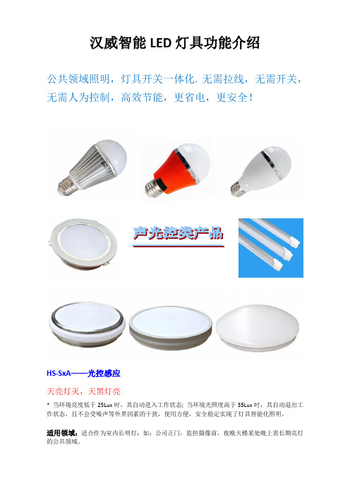
汉威智能LED灯具功能介绍公共领域照明,灯具开关一体化,无需拉线,无需开关,无需人为控制,高效节能,更省电,更安全!HS-SxA——光控感应天亮灯灭,天黑灯亮* 当环境亮度低于25Lux时,其自动进入工作状态; 当环境光照度高于35Lux时,其自动退出工作状态,且不会受噪声等外界因素的干扰,使用方便,安全稳定实现了灯具智能化照明。
适用领域:适合作为室内长明灯;如:公司正门,监控摄像前,夜晚大楼某处晚上需长期亮灯的公共领域。
HS-SxB——声光控感应白天灯灭,晚上声音达到60分贝时灯才亮,白天声音再大也不亮。
* 通电时感应灯管温机30秒(灯会亮),然后灭掉进入感应状态。
* 当环境亮度低于25LUX时(日落黄昏状态),声音大于60db时灯管会自动亮,亮一次的时间为2分钟(可以设置时间),当环境亮度高于35Lux时,灯具自动退出。
* 声光控灯具感应范围为半径8M,声音越大感应的距离越远。
感应一次亮灯2分钟,如人一直在感应区域内持续或间隔发出声音,感应球泡会一直亮。
适用领域:适合远距离控制,但在光线足够的情况下怎么大的音量也不会亮,如楼道,地下停车场,走道,洗手间等。
HS-SxC——双亮声控感应通电后,没声音时,灯亮30%,声音大于60分贝时,灯全亮,声音停止后,灯恢复到30%亮度。
1、通电时灯具温机30秒(此时灯会亮),然后灭掉进入感应状态。
2、感应状态下灯具微亮30%亮(如10W灯具微亮为3W),当声音大于60分贝时灯具会自动全亮,全亮一次的时间为2分钟(可以设置时间)。
3、灯具感应范围为半径5M,当传递的声音大于60db,或声音一直在感应范围内持续或间隔发出,并大于60db,感应灯具会一直全亮。
当声音小于60db,2分钟后灯具进入微亮(30%)状态。
适用领域:适合远距离控制,且适合必须要有一定亮度的空间,微亮节能及保障基本亮度,声音传递距离比较远。
如,暗走道,走廊。
楼道等。
HS-SxD——光控红外感应白天灯灭,晚上有人或车进到感应范围灯才亮,白天有人进入也不亮。
金鹏实业 OCMC4X20 字符点阵液晶显示模块 说明书

OCMC4X20字符点阵液晶显示模块使用说明书-----------------------------------------------------------------感谢您关注和使用金鹏字符点阵系列液晶显示器产品,欢迎您提出意见和建议,我们将竭诚为您服务、让您满意。
您可以浏览 了解最新的产品与应用信息,或拨打热线电话0758-2317156及向syl@邮箱发E-mail获取具体的技术咨询与服务。
金鹏实业有限公司Golden Palm Industry Co., Ltd.目录1、产品简介 (3)2、引用文件 (3)3、机械特性 (3)4、产品框图 (3)5、电气特性 (4)6、极限参数 (4)7、接口时序 (4)8、直流特性 (6)9、引脚描述 (7)10、命令描述 (8)11、附录 (12)附录1 程序参考 (12)附录2 字符表 (15)附录3 模块外形图 (16)1、 产品简介主要工艺:COB显示内容:4行每行20个字符 显示模式:STN ,POSITIVE 驱动条件:1/16Duty 1/5Bias 视向:6:00背光:LED ,黄绿色工作温度:常温 0℃~55℃/ 宽温-20℃~+70℃ 储存温度:常温 -10℃~60℃/ 宽温-30℃~+80℃ 控制IC :S6A0069/KS00662、 引用文件S6A0069 规格书3、机械特性类别 标准值单位 模块 98.0(w)X60.0(h)X14.0 (t)mm 有效显示区 76.0(w)X25.9(h) mm 点大小 0.5(w)X0.5 (h) mm 点间隙 0.05(w)X0.05(h) mm 字符大小2.95(w)X4.75(h)mm4、产品框图5电气特性类别 符号 条件 最小值 TYP 最大值 单位 驱动电压 Vop. 25℃ 4.0 5.0 10.0 V 响应时间 Ton 25℃ — 127 200 Ms Toff25℃—263360Ms对比度CR25℃ — 9 — — 视角范围 25℃ — 60 — DEG 交叉效应25℃—1.2——6、极限参数参数 符号 最小值 最大值 单位 逻辑电压 Vdd-0.3 +5.5 V 驱动电压 Vout,VO -0.3 -10 V 工作温度 Top -20 +70 ℃ 存储温度Tst-30+80℃7、接口时序 1)读操作项 目符号条件最小值 最大值 单位E 周期 t cycE 1,200 - E 脉宽(高电平) PW EN 140 - E 上升/下降时间 t Er ,t Ef - 25地址设置时间(RS ,R/W ,E ) t AS 0 -地址保持时间 t AH 10 - 数据延迟时间 t DDR -100 数据保持时间 t DHRVdd=5V ±5%Vss=0V Ta=25℃10 -ns2)写操作项 目符号条件最小值 最大值 单位E 周期 t cycE 1,200 - E 脉宽(高电平) PW EN 140 - E 上升/下降时间 t Er ,t Ef - 25地址设置时间(RS ,R/W ,E ) t AS 0 -地址保持时间 t AH 10 - 数据设置时间 t DSW 40 - 数据保持时间 t HVdd=5V ±5%Vss=0V Ta=25℃10 -ns8、直流特性9、引脚描述引脚名称方向说明1 Vss -- 电源地(0V)2 Vdd -- 电源电压(+5V)3 Vo -- LCD驱动电压(可调,一般为0.8V)4 RS I RS=0,选择指令寄存器;RS=1,选择数据寄存器5 R/W I R/W=0 写操作;R/W=1 读操作6 E I 写操作时,信号下降沿有效;读操作时,高电平有效7 DB0 I/O 8位总线模式为数据口0,4位总线模式下D0~D3脚断开8 DB1 I/O 8位总线模式为数据口1,4位总线模式下D0~D3脚断开9 DB2 I/O 8位总线模式为数据口2,4位总线模式下D0~D3脚断开10 DB3 I/O 8位总线模式为数据口3,4位总线模式下D0~D3脚断开11 DB4 I/O 8位总线模式为数据口4,4位总线模式下D0~D3脚断开12 DB5 I/O 8位总线模式为数据口5,4位总线模式下D0~D3脚断开13 DB6 I/O 8位总线模式为数据口6,4位总线模式下D0~D3脚断开14 DB7 I/O 8位总线模式为数据口7,4位总线模式下D0~D3脚断开15 LED+ -- 背光电源正(+5V)16 LED- -- 背光电源地(0V)注:15、16背光引脚可以根据需要调整为15=LED- ;16=LED+10、命令描述指令表:Instruction CodeInstructionRS R/W DB7 DB6 DB5 DB4 DB3 DB2 DB1 DB0DescriptionInstruction CodeExecutiontime(fsoc=270)Clear Display0 0 0 0 0 0 0 0 0 1 Write "20H" to DDRAM. andset DDRAM address to"00H" fromAC.1.53msReturn Home0 0 0 0 0 0 0 0 1 X Set DDRAM address to"00H"from AC and return cursorto its original position ifshifted. The contents ofDDRAM are notchanged.1.53msEntry Mode Set 0 0 0 0 0 0 0 1 I/D SHAssign cursor movingdirection and make shift ofentire display enable.39µsDisplayON/OFF Control 0 0 0 0 0 0 1 D C BSet display(D), cursor(C),and blinking of cursor(B)on/off control bit.39µsCursor or Display Shift 0 0 0 0 0 1 S/C R/L X XSet cursor moving anddisplay shift control bit, andthe direction, withoutchanging DDRAM data.39µsFunction Set0 0 0 0 1 DL N F X X Set interface data length(DL : 4-bit/8-bit), numbers ofdisplay line (N :1-line/2-line), display fonttype (F : 5 X 8 dots/ 5 X 11dots)39µsSet CGRAM Address 0 0 0 1 AC5 AC4 AC3 AC2 AC1 AC0Set CGRAM address inaddress counter.39µsSet DDRAM Address 0 0 1 AC6 AC5 AC4 AC3 AC2 AC1 AC0Set DDRAM address inaddress counter.39µsRead BusyFlag and Address 0 1 BF AC6 AC5 AC4 AC3 AC2 AC1 AC0Whether during internaloperation or not can beknown by reading BF. Thecontents of address countercan also be read0µsWrite Data to RAM 1 0 D7 D6 D5 D4 D3 D2 D1 D0Write data into internal RAM(DDRAM/CGRAM).43µsRead Data from RAM 1 1 D7 D6 D5 D4 D3 D2 D1 D0Read data from internalRAM (DDRAM/CGRAM).43µs指令介绍:由于MPU可以直接访问模块内部的IR和DR,作为缓冲区域,IR和DR在模块进行内部操作之前,可以暂存来自MPU的控制信息。
用户手册 - 如何使用灯库说明书
用户手册如何使用灯库V1.5.1目录简介说明 (3)打开配接管理器 (4)加载灯库到配接管理器 (5)从列表中配接灯库 (5)从灯库编辑器加载 (7)配接命令工具 (8)在配接管理器中更新灯库文件 (9)在配接管理器中添加和更新矩阵 (10)倒转X/Y通道 (10)更改DMX地址 (11)新建一个矩阵 (11)矩阵工具栏 (13)模拟和检查DMX地址码 (14)矩阵灯单元的排序 (14)手动修改单个DMX地址 (15)删除部分矩阵 (15)修改和更新配接 (16)软件配接效果显示 (16)本章介绍如何使用灯库管理器编辑和添加灯库文件。
粘贴灯具,也就是给灯具分配具体的DMX地址。
国际通用的DMX地址是从1到512个通道地址。
所有的软件、控制器单个口最大支持512个通道。
在软件中设置灯具的通道地址必须和灯具本身设置的DMX地址一致。
使用软件控制灯具之前,要确保驱动及配置文件安装正确。
Video tutorials are available online灯具厂家列表当前添加的可用的灯库文件DMX 地址设置将正在制作的灯库文件粘贴当DMX 地址网里矩阵编辑器将选择的灯库文件粘贴到DMX 地址网DMX 域选择栏DMX 地址网单击+号按钮,打开灯库编辑器窗口,你可以在这个窗口更新适配灯库。
灯库编辑器有两个部分。
左边部分是灯库文件及相关信息,右边是DMX 地址网络,灯具放在右边的地址网格中才有效。
所有灯具的第一个DMX 通道号必须与灯具本身上的DMX 地址匹配。
加载灯库到配接管理器两个方式加载灯库,配接对应的DMX512通道地址即可控制对应的灯具:从列表中配接灯库从列表中,通过以下6个步骤添加现有的内置灯库:从灯库编辑器加载从灯库列表加载1.选择‘从列表中粘贴’(软件默认选择)2.从下拉列表中选择一个灯具制造商,再选择对应的灯库文件加载配接3.选择需要配接地址的U 域4.选择第一个DMX 通道地址(第一个灯具的首个地址码)5.当前选择的灯库的通道数(如当前灯库是6通道灯具)6.点击‘贴上’将选中的灯库配接到DMX 地址网格点击打开灯库文件夹默认情况是当前选中的地址码如下图,你可以看到有6个RGB 的LED 灯被配接到DMX 地址网格中,对应的DMX 地址码是1~18。
LED点阵显示屏设计说明书
目录摘要 (1)前言 (2)1 概述 (2)1.1 LED电子显示屏的分类 (2)1。
2 LED显示屏的应用示例 (2)1。
3 设计任务 (2)2 显示原理及控制方式分析 (3)2.1 LED点阵模块结构 (3)2。
2 LED 动态显示原理 (3)2.3 LED常见的控制方式 (5)3 总体方案设计与分析 (6)3.1显示单元的考虑 (6)3。
2 滚屏的实现 (6)3。
3 关于可扩展性 (6)3。
4 微控制器的考虑 (6)3.5 总体电路结构及工作原理 (6)3.5。
1 硬件电路框图 (6)3.5。
2 工作原理 (7)4 硬件电路设计 (7)4。
1 显示单元电路设计 (7)4。
1。
1 LED点阵模块的选择 (8)4.1.2 列驱动电路设计 (8)4。
1。
3 行驱动电路设计 (9)4.2 单片机控制系统电路设计 (10)4.2.1单片机的选型 (10)4。
3对于系统电源及通信电缆的选择 (11)4。
4 其它元件的选择 (11)5 单片机软件设计与仿真 (12)5.1 开发工具及语言 (12)5。
2 单片机软件流程 (13)5。
3 单片机软件中算法的实现 (14)5.4 调试及仿真结果 (15)6 PCB设计及硬件调试 (16)6。
1 PCB设计平台 (16)6.2元件布局及PCB整体结构工艺 (16)6。
3 布线工艺与准则 (16)7 总结 (17)谢辞............................................................................................ 错误!未定义书签。
参考文献. (18)附录 (19)LED点阵电子显示屏系统的设计xxx摘要:本设计使用STC系列高速单片机作为主控制模块,利用简单的外围电路来驱动16×64的点阵LED显示屏。
本LED显示屏能够以动态扫描的方式同时显示特定的四个16×16点阵汉字。
Viscor BEVEL LED - 建筑性架空灯具说明书
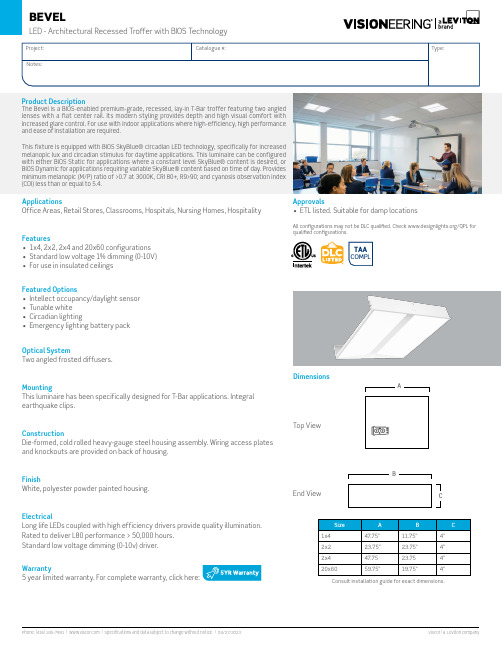
TAACOMPLApplicationsOffice Areas, Retail Stores, Classrooms, Hospitals, Nursing Homes, Hospitality Features• 1x4, 2x2, 2x4 and 20x60 configurations • Standard low voltage 1% dimming (0-10V)• For use in insulated ceilingsFeatured Options• Intellect occupancy/daylight sensor • Tunable white • Circadian lighting• Emergency lighting battery packOptical SystemTwo angled frosted diffusers.MountingThis luminaire has been specifically designed for T-Bar applications. Integral earthquake clips.ConstructionDie-formed, cold rolled heavy-gauge steel housing assembly. Wiring access plates and knockouts are provided on back of housing.FinishWhite, polyester powder painted housing.ElectricalLong life LEDs coupled with high efficiency drivers provide quality illumination.Rated to deliver L80 performance > 50,000 hours.Standard low voltage dimming (0-10v) driver.Warranty5 year limited warranty. For complete warranty, click here:Consult installation guide for exact dimensions.Product DescriptionThe Bevel is a BIOS-enabled premium-grade, recessed, lay-in T-Bar troffer featuring two angled lenses with a flat center rail. Its modern styling provides depth and high visual comfort with increased glare control. For use with indoor applications where high-efficiency, high performance and ease of installation are required.This fixture is equipped with BIOS SkyBlue® circadian LED technology, specifically for increased melanopic lux and circadian stimulus for daytime applications. This luminaire can be configured with either BIOS Static for applications where a constant level SkyBlue® content is desired, or BIOS Dynamic for applications requiring variable SkyBlue® content based on time of day. Provides minimum melanopic (M/P) ratio of >0.7 at 3000K, CRI 80+, R9>90; and cyanosis observation index (COI) less than or equal to 5.4.Approvals• ETL listed. Suitable for damp locationsAll configurations may not be DLC qualified. Check /QPL for qualified configurations.DimensionsTop ViewEnd ViewOrder KeyPerformance DataPackaging Options K0 Bulk Pack/Pallet Packed and/or Wrapped Wiring Options V09 Flexible Whip (standard 6Ft. x 3-18 ga.)^ 90+ CRI reduces lumen output by 20%, not available with 5000K *** When Selecting 2765KT, if a tunable white-compatible control is not selected the luminaire will come standards with two sets of 0-10V wires for dimming and color tuning (see tunable white diagram for details). For compatible control options please consult factory.Other options may be available, consult factory. Specifications and data subject to change without notice.EXAMPLE: BVL2x2-LED840K042LUNV*3000Lm Example:BVL2x2-LED840K030LC UNV 035L - 3500042L - 4200050L - 5000025L - 2500035L - 3500042L - 4200050L - 5000060L - 6000070L - 7000_ _ _L*2x 4C u s t o mL u m e n s1x 42x 2V114(BI03) - BIOS Dynamic Tunable Circadian LED (tunable to 2700K)Ordering Key ExampleBVL2x2-LED840K035LUNV-V114(BI02)• Static CCT (4000K) fixture, output dimmable to 1%• SkyBlue™ is always presentBVL2x2-LED840K035LUNV-V114(BI03)• 2-Channel Tunable (4000K - 2700K) fixture dimmable to 1%• SkyBlue™ is always present from 4000k-3000kBVL2x2-LED840K035LUNV-V114(BI01)• Single-Channel Bio-Dimming from 4000K with SkyBlue™ to >2700K• At 2700K, dim total output to 1%• At 2700K, SkyBlue™ no longer presentBIOS Static Circadian LED Solution - V114 (BI02)BIOS SkyBlue® Spectrum lighting solutions support proper daytime circadian stimulus, communicating directly with human circadian biology through a non-visual photo receptor in the eye.Static Engine Spectral Power Distribution (3500K)BIOS Static Spectrum Light Engine delivers the industry’s best melanopic-to-photopic (M/P) ratio, with R9 greater than 90 at each color temperature. BIOS Static Spectrum Light Engine is the ideal replacement for static color light fixtures.PeakMelanopsinSensitivityNominal Performance¹ M/P is a ratio that describes the relative melanopic lux (M) versus the photopic lux (P)² COI - Cyanosis Observation IndexBIOS Dynamic Circadian LED Solution - V114 (BI01)BIOS SkyBlue® Dynamic Light Engine provides full daytime circadian stimulus and can be dynamically adjusted via the Bio-Dimming™ module. Using a standard single channel 0-10V dimmer reducing melanopic lux while keeping light and CCT constant3. When the SkyBlue® content has been removed (at 2700K), the light level can be adjusted. The Bio-Dimming™ module also detects the preferred light levels over time and will adjust the high end trim of the system to those preferences.Nominal Performance3 CCT may vary by up to 500K4Value as shown represents COI provided by daytime LED Spectrum.Dynamic Engine Spectral Power Distribution (3500K)80%B i o -a D i m m i n g PeakMelanopsin SensitivityNighttime SPDDaytime SPDBIOS Dynamic Circadian LED + Bio-Dimming™BIOS Dynamic Circadian LED Solution - V114 (BI03)BIOS SkyBlue® Dynamic Light Engine provides full daytime circadian stimulus and can be dynamically adjusted via tunable circadian LED module. Using a standard two channel 0-10V dimmer reducing melanopic lux and adjusting the output light level while keep CCT constant3. The SkyBlue® below 3000K no longer present. The tunable module also detects the preferred light levels over time and will adjust the high end trim of the system to those preferences.Nominal Performance3 CCT may vary by up to 500K4Value as shown represents COI provided by daytime LED Spectrum.BIOS Dynamic Tunable Circadian LED (tunable to 2700K)Dynamic Engine Spectral Power Distribution (3500K)B i o -a D i m m i n g PeakMelanopsin SensitivityNighttime SPDDaytime SPD。
舞台灯光设备(LED电视平板灯)
6
XM1148/1266-V1.0-E
5. 安装指导
警告: 请勿在机箱打开的情况下运行灯具;禁止灯具运行过程中开启机箱盖。
5.1 灯具的悬挂安装
警告: 请考虑GB7000.1-2007,GB7000.217-2008标准且结合各自国家的规范进行安装。 强烈要求由有资格的专业技术人员执行操作。
灯具的悬吊支架必须能承载灯具 10 倍的重量,且悬挂 1 小时后都无任何变形。 请让专业人士对其电气参数进行核准后再安装,操作员必需确保灯具是安全连接。 当对灯具进行安装、拆装、移动或维修时,请勿站在灯具正下方。 电源线端插头的连接,电源线更改时,必须由有相应资格的专业人员操作。 确保让相关专家最少每年检查一次这些安装。 使用者请确保对灯具及其安装材料作定期的安全性检查。如果缺乏进行这些工作的条件和专业
流明数据பைடு நூலகம்DMX通道图
5
XM1148/1266-V1.0-E
3. 灯体概述 4. 产品尺寸图
1) 显示窗口 2) 向左-按键 3) 模式/退出-按键 4) 向上-按键 5) 确认-按键 6) 向右-按键 7) 向下-按键 8) 八页门组件 9) 信号输入 10) 信号输出 11) 电源输入 12) 电源开关
作。切勿让非专业人员进行安装、操作。 请妥善保存本灯具的包装泡沫、纸箱等包装材料,以备将来需要搬运时使用。 本灯具适用的环境温度范围是-10o C~ 45oC,请勿在过高或过低的环境中使用此灯具。 请严格遵照本手册的指引进行安装操作,任何因误装误用而导致的故障,不在本公司承诺的保修范
围内。此外,任何违规的操作可能会导致短路、烧伤、电击、灯爆裂、坠毁等严重后果。
舞台灯光设备(LED电视平板灯)
操作使用说明
ECO Spot LED C20PCE 使用手册说明书
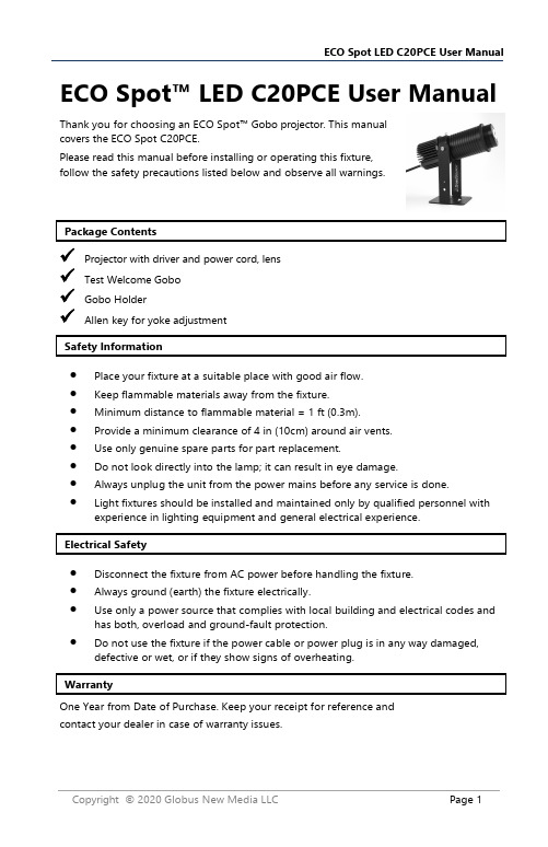
✓Projector with driver and power cord , lens ✓Test Welcome Gobo ✓Gobo Holder✓Allen key for yoke adjustmentcontact your dealer in case of warranty issues.ECO Spot™ LED C20PC E User ManualThank you for choosing an ECO Spot™ Gobo projector. This manual covers the ECO Spot C20PC E .Please read this manual before installing or operating this fixture, follow the safety precautions listed below and observe all warnings.•Place your fixture at a suitable place with good air flow.•Keep flammable materials away from the fixture.•Minimum distance to flammable material = 1 ft (0.3m).•Provide a minimum clearance of 4 in (10cm) around air vents.•Use only genuine spare parts for part replacement.•Do not look directly into the lamp; it can result in eye damage.•Always unplug the unit from the power mains before any service is done.•Light fixtures should be installed and maintained only by qualified personnel with experience in lighting equipment and general electrical experience.•Disconnect the fixture from AC power before handling the fixture.•Always ground (earth) the fixture electrically.•Use only a power source that complies with local building and electrical codes and has both, overload and ground-fault protection.•Do not use the fixture if the power cable or power plug is in any way damaged,defective or wet, or if they show signs of overheating.projection size and resulting brightness at varying distances. The narrower the lens, the smaller and brighter the image will be at a given distance.•Before the initial start-up, please unpack and carefully check for damage caused during transportation.•Place your fixture at a suitable place with good air flow.•Make sure there are no flammable materials close to the lamp.•When suspending the fixture above ground level, verify that the structure can hold at least 10 times the weight of all installed devices.•Verify that all external covers and rigging hardware are securely fastened and use an approved means of secondary attachment such as a safety cable.•Power up the projector by pressing the power switch in the back.•Focus the projection by twisting the lens in and out until the image is well focused.When used for the first time, the lens will often need to be twisted outwards many rotations to reach the focusing point.•Re-adjust the focus if necessary.•The projector is mainly designed for wall and ceiling mounting but in many cases,it can also be placed on a table or shelf.•The yoke allows projector movement in one direction:Up/down .•Unscrew the thumbscrew and screw into gobo holder to remove.•Push the two pins of the gobo retaining ring together and pull out the retaining ring. Carefully remove the old gobo and replace it with the new gobo.•If you have a glass gobo, place the more reflective side towards the light bulb.•Replace the retaining ring and make sure it evenly pushes the gobo all the way back.•Pl ace the gobo holder in the slot and unscrew the thumb screw to lock it. Screw the thumb screw into thread in front of gobo holder so it is not lost. A djust the focus by screwing the projection lens in or out until you reach a focal point, then fine tuning focus can be down with single turns to achieve full focus.Total Length:8 - 10" - depends on lens Total Height: 5.5" (incl. yoke) Weight: 2.4lbsThe projection lens adds 0.5 to 2in (12 to 50mm) to the length.with up to 3.3mm thickness. Film Gobo Life - 2 - 5 days.Standard gobo size (E-Size):Outer Diameter (OD): 37.5mmImage Diameter (ID): 27mm (max 32mm) The recommended gobo image diameter for best focusing is up to 25mm. An image diameter of up to 32mm is possible with some yellowing and focusing weakness in the outer projection area.standard ECO Spot projection lenses.A larger focal length (f) makes a smaller projection angle and therefore a smaller but brighter image. Currently these lenses are available:•Power: 20W•Rated luminous flux: 1,800lm •Effective luminous flux: 1,000lm •Rated Bulb life 30,000h •Color Temperature 7,000k,+/-500k•Wide f=56mm, 25º•Semi-Narrow f=100mm, 15º。
点阵屏雨棚灯使用说明书新
点阵屏雨棚灯使用说明书一、概述雨棚信号灯安装在每一车道上方的遮棚上,每一车道安装一对雨棚信号灯,分为前向信号灯和后向信号灯。
点阵屏雨棚灯适用于在车道迎车流行驶方向的遮棚上方安装,称为前向信号灯。
此产品包含组合信号灯(可分别显示红色(用×表示)、绿色(用↓表示)两种行车信号)和汉字显示区。
根据型号不同,雨棚信号灯可显示4或2个汉字,采用通用的串口RS323方式控制显示内容。
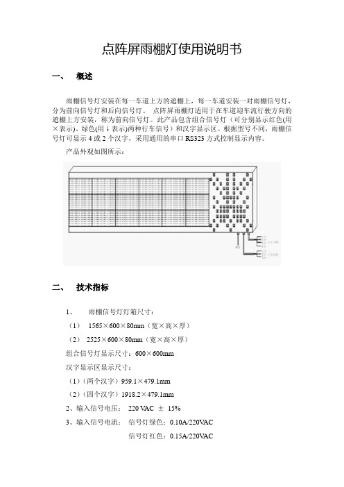
产品外观如图所示:二、技术指标1、雨棚信号灯灯箱尺寸:(1)1565×600×80mm(宽×高×厚)(2)2525×600×80mm(宽×高×厚)组合信号灯显示尺寸:600×600mm汉字显示区显示尺寸:(1)(两个汉字)959.1×479.1mm(2)(四个汉字)1918.2×479.1mm2、输入信号电压:220 V AC ±15%3、输入信号电流:信号灯绿色:0.10A/220V AC信号灯红色:0.15A/220V AC汉字显示点阵:1.047A/220V AC4、工作环境温度:-30~65℃5、工作环境湿度:< 95%6、可视距离:≥300米7、MTBF:50000小时8、MTTR:﹤0.5小时9、信号灯红色LED亮度> 8000cd/平方米信号灯绿色LED亮度> 10000cd/平方米汉字显示点阵LED亮度> 6000cd/平方米10、超高亮度红色LED光源:直径26mm,由4个超高亮度红色LED组成11、超高亮度绿色LED光源:直径26mm,由3个超高亮度绿色LED组成12、半角功率角≥30°三、安装及使用1.安装雨棚灯的顶部有四个固定孔,可根据实际情况使用抱箍将其安装在收费雨棚的顶部。
安装时确保安装牢靠,接线正确。
2.接线(1)点阵屏雨棚灯的组合信号灯点阵屏雨棚灯的组合信号灯分为红叉“╳”和绿箭头“↙”两种状态,其控制电源为灯箱右下角的1号线(如图-S),1号线为4芯线,分为棕、蓝、黑、黄四种颜色。
工light系列LED伞灯(24V)橱柱安装指南说明书
Installation Guide:Worklight Series LED Floodlight (24V)Horizontal Mount©2011 Whelen Engineering Company Inc.Form No.14494A (051711)For warranty information regarding this product, visit /warranty•Proper installation of this product requires the installer to have a good understanding of automotive electronics, systems and procedures.•Whelen Engineering requires the use of waterproof butt splices and/or connectors if that connector could be exposed to moisture.•Any holes, either created or utilized by this product, should be made both air- and watertight using a sealant recommended by your vehicle manufacturer.•Failure to use specified installation parts and/or hardware will void the product warranty.•If mounting this product requires drilling holes, the installer MUST be sure that no vehicle components or other vital parts could be damaged by the drilling process. Check both sides of the mounting surface before drilling begins. Also de-burr the holes and remove any metal shards or remnants. Install grommets into all wire passage holes.•If this manual states that this product may be mounted with suction cups, magnets, tape or Velcro®, clean the mounting surface with a 50/50 mix of isopropyl alcohol and water and dry thoroughly.•Do not install this product or route any wires in the deployment area of your air bag. Equipment mounted or located in the air bag deployment area will damage or reduce the effectiveness of the air bag, or become a projectile that could cause serious personal injury or death. Refer to your vehicle owner’s manual for the air bag deployment area. The User/Installer assumes full responsibility to determine proper mounting location, based on providing ultimate safety to all passengers inside the vehicle.•For this product to operate at optimum efficiency, a good electrical connection to chassis ground must be made. The recommendedprocedure requires the product ground wire to be connected directly to the NEGATIVE (-) battery post (this does not include products that use cigar power cords).•If this product uses a remote device for activation or control, make sure that this device is located in an area that allows both the vehicle and the device to be operated safely in any driving condition.•Do not attempt to activate or control this device in a hazardous driving situation.•This product contains either strobe light(s), halogen light(s), high-intensity LEDs or a combination of these lights. Do not stare directly into these lights. Momentary blindness and/or eye damage could result.•Use only soap and water to clean the outer lens. Use of other chemicals could result in premature lens cracking (crazing) and discoloration. Lenses in this condition have significantly reduced effectiveness and should be replaced immediately. Inspect and operate this product regularly to confirm its proper operation and mounting condition. Do not use a pressure washer to clean this product.•It is recommended that these instructions be stored in a safe place and referred to when performing maintenance and/or reinstallation of this product.•FAILURE TO FOLLOW THESE SAFETY PRECAUTIONS AND INSTRUCTIONS COULD RESULT IN DAMAGE TO THE PRODUCT OR VEHICLE AND/OR SERIOUS INJURY TO YOU AND YOUR PASSENGERS!A u t o m o t i v e : Warnings to InstallersWhelen’s emergency vehicle warning devices must be properly mounted and wired in order to be effective and safe. Read and follow all of Whelen’s written instructions when installing or using this device. Emergency vehicles are often operated under high speed stressful conditions which must be accounted for when installing all emergency warning devices. Controls should be placed within convenient reach of the operator so that they can operate the system without taking their eyes off the roadway. Emergency warning devices can require high electrical voltages and/or currents. Properly protect and use caution around live electrical connections.Grounding or shorting of electrical connections can cause high current arcing, which can cause personal injury and/or vehicle damage, including fire. Many electronic devices used in emergency vehicles can create or be affected by electromagnetic interference. Therefore, after installation of any electronic device it is necessary to test all electronic equipment simultaneously to insure that they operate free of interference from other components within the vehicle. Never power emergency warning equipment from the same circuit or share the same grounding circuit with radio communication equipment. All devices should be mounted in accordance with the manufacturer’s instructions and securely fastened to vehicle elements of sufficient strength to withstand the forces applied to the device. Driver and/or passenger air bags (SRS) will affect the way equipment should be mounted. This device should be mounted by permanent installation and within the zones specified by the vehicle manufacturer, if any. Any device mounted in the deployment area of an air bag will damage or reduce the effectiveness of the air bag and may damage or dislodge the device. Installer must be sure that this device, its mounting hardware and electrical supply wiring does not interfere with the air bag or the SRS wiring or sensors. Mounting the unit inside the vehicle by a method other than permanent installation is not recommended as unit may become dislodged during swerving; sudden braking or collision. Failure to follow instructions can result in personal injury. Whelen assumes no liability for any loss resulting from the use of this warning device. PROPER INSTALLATION COMBINED WITH OPERATOR TRAINING IN THE PROPER USE OF EMERGENCY WARNING DEVICES IS ESSENTIAL TO INSURE THE SAFETY OF EMERGENCY PERSONNEL AND THE PUBLIC.Warnings to UsersWhelen’s emergency vehicle warning devices are intended to alert other operators and pedestrians to the presence and operation of emergency vehicles and personnel. However, the use of this or any other Whelen emergency warning device does not guarantee that you will have the right-of-way or that other drivers and pedestrians will properly heed an emergency warning signal. Never assume you have the right-of-way. It is your responsibility to proceed safely before entering an intersection, driving against traffic, responding at a high rate of speed, or walking on or around traffic lanes. Emergency vehicle warning devices should be tested on a daily basis to ensure that they operate properly. When in actual use, the operator must ensure that both visual and audible warnings are not blocked by vehicle components (i.e.: open trunks or compartment doors), people, vehicles, or other obstructions. It is the user’s responsibility to understand and obey all laws regarding emergency warning devices. The user should be familiar with all applicable laws and regulations prior to the use of any emergency vehicle warning device. Whelen’s audible warning devices are designed to project sound in a forward direction away from the vehicle occupants. However, because sustained periodic exposure to loud sounds can cause hearing loss, all audible warning devices should be installed and operated in accordance with the standards established by the National Fire Protection Association.Safety FirstThis document provides all the necessary information to allow your Whelen product to be properly and safely installed. Before beginning the installation and/or operation of your new product, the installation technician and operator must read this manual completely. Important information is contained herein that could prevent serious injury or damage.WARNING: This product can expose you to chemicals including Methylene Chloride which is known to the State of California to cause cancer, and Bisphenol A, which is known to the State of California to cause birth defects or other reproductive harm. For more information go to .51 Winthrop RoadChester, Connecticut 06412-0684Phone: (860) 526-9504Internet: Salese-mail:*******************CustomerServicee-mail:*******************®ENGINEERING COMPANY INC.Mounting...1.Position the appropriate mounting bracket (Item #5 or #6) onto the proposedmounting surface. Mark the areas where the mounting holes are to be drilled.2.Drill the mounting holes required using an appropriately sized drill bit (refer to theMounting Hole Specifications shown below).IMPORTANT NOTE! This installation uses Rivnuts to secure the brackets to the vehicle. This type of hardware requires the use of a specialized installation tool. Refer to the owners manual included with this tool for proper installation techniques. Be sure to follow the mounting hole specifications precisely!3.With the Rivnuts properly installed, position the appropriate seal (#7 or #8) overthe mounting holes and position the mounting bracket onto the seal. The bracket can now be mounted onto the vehicle using the appropriate hardware (Items #4, #2 & #3). Apply a drop of LocTite 242 to each of the mounting bolts and insert them into their Rivnut. Tighten each bolt to 50 in/lbs.4.Secure the appropriate worklight mounting bracket (Item #10 or #11) to theworklight assembly using Items #12 & #13 (apply a drop of LocTite® 242 to the threads).ing the appropriate hardware (Items #1, #2 & #3), install the floodlight assemblyonto the mounting bracket.6.Adjust the floodlight to the desired angle and tighten the hardware firmly tomaintain that angle.Wiring...All customer supplied wires that connect to the positive terminal of the battery must be sized to supply at least 125% of the maximum operating current and FUSED at the battery to carry that load. DO NOT USE CIRCUIT BREAKERS WITH THIS PRODUCT!Worklight Single...1.Extend the RED wire to the customer supplied SP/ST switch. From the switch,extend an appropriately sized wire to the POS battery terminal. Fuse this wire @ 3 Amps (customer supplied).2.Extend the BLACK/WHITE wire to chassis groundWorklight Dual...1.Extend one of the RED wires to the customer supplied SP/ST switch designatedto control LED Board #1. From this switch, extend an appropriately sized wire to the POS battery terminal. Fuse this wire @ 3 Amps (customer supplied).2.Extend the other RED wire to the customer supplied SP/ST switch designated tocontrol LED Board #2. From this switch, extend an appropriately sized wire to the POS battery terminal. Fuse this wire @ 3 Amps (customer supplied).3.Extend and connect the BLK/WHT wires to chassis ground.Alternate Wiring Style - If the user chooses, a single switch of sufficient capacity may be used to activate both LED boards simultaneously (see below). From this switch, extend an appropriately sized wire to the POS battery terminal. Fuse this wire @ 5 Amps (customer supplied).IMPORTANT! Before returning the vehicle to active service, visually confirm the proper operation of this product, as well as all vehicle components/ equipment.。
led lamp使用方法

led lamp使用方法宝子们,今天来唠唠LED灯(LED lamp)的使用方法呀。
咱先说说那种最常见的LED灯泡。
你要是想把它装在灯座上,可一定要先把电闸给拉了哦,安全第一嘛。
然后拿着灯泡,就像拿着个小宝贝似的,小心地对准灯座的螺口,轻轻地拧进去。
可别使太大劲,要是把灯泡拧坏了,那可就不好玩啦。
拧好之后呢,再把电闸推上去,“啪”的一下,亮堂堂的世界就来啦。
要是那种带灯罩的LED灯呀,有的灯罩是可以直接取下来的。
在换灯泡或者做清洁的时候,你就瞅准了灯罩的卡扣或者螺丝啥的。
如果是卡扣,就轻轻一掰,灯罩就下来了。
要是螺丝呢,找个小螺丝刀,把螺丝拧松,灯罩也就乖乖听话了。
换好灯泡或者清理好灰尘之后,再把灯罩安回去,就像给小灯戴帽子一样,要盖得稳稳的哦。
还有那种LED灯带呢。
这玩意儿可好玩啦。
在安装之前,要先确定好你想把它贴在哪里。
一般灯带后面都有那种粘性很强的胶,你把要贴的地方擦得干干净净的,一点灰尘都不能有,就像给它准备一个超干净的小窝。
然后把灯带小心翼翼地贴上去,边贴边按压,让它和粘贴面紧紧地抱在一起。
要是想把灯带剪成合适的长度,一定要按照灯带上面的标记来剪哦,不然剪坏了它可就没法亮啦。
再说说那种可以调节亮度和颜色的LED灯。
通常会有个小遥控器或者灯上有按钮。
要是遥控器的话,你就拿着遥控器,像魔法师拿着魔法棒一样。
想调亮一点,就按那个亮度增加的键,想暗一点就按相反的键。
要是想换颜色呢,就按颜色切换的键,看着灯光在各种颜色之间变来变去,是不是超级有趣呀。
要是灯上有按钮,也是一样的操作啦,按按按,按出你想要的灯光效果。
宝子们,LED灯的使用方法其实很简单的,只要咱们稍微注意一下,就能让它好好地为我们照亮啦。
3208LED点阵屏电子钟使用说明书

3208LED点阵屏电子钟使用说明书1LED LED点阵屏电子钟点阵屏电子钟点阵屏电子钟[性能简介性能简介]]·靓丽的显示屏幕靓丽的显示屏幕::采用32*8 高亮度红色LED 点阵列作为屏幕显示,使时钟更醒目。
·丰富的显示信息丰富的显示信息::支持日期、星期、时间和温度的交替显示,使显示的信息量更大。
·更人性化的时间切换更人性化的时间切换::时间停留2 秒,日期、星期停留1秒,使重要信息一目了然。
·特殊的调时功能特殊的调时功能::4 个调时操作键,分区加数调时方法,使调时更快捷。
·人性化的整点报时人性化的整点报时::整点报时的区间为早晨7 点到晚上9 点,不打扰夜间休息。
·精确的温度数据精确的温度数据::采用精确的数字式温度传感器,温度误差更小。
·先进的时钟系统先进的时钟系统::采用专用的时钟芯片,可自动完成2100 年之前的时间显示。
·不间断的走时不间断的走时::采用大容量备用电池,使外电源掉电后时钟仍能走时3 年以上。
·外挂式温度传感器外挂式温度传感器::用导线将温度传感器远离主体电路,避免主体电路发热干扰。
[组装与启动组装与启动]]A,B,C,D 四个按键,A 为“调时切换键”,B 为“内容切换键”,C 为“屏幕前位数据加1”,D 为“屏幕后位数据加1”按下时钟主体背面的电源开关(如图6)后,在LED 显示屏上会显示“DYDIY”字样,同时扬声器发出开机音乐用以测试显示屏和扬声器。
此后系统将自检各项功能,屏幕上可能会出现不正常的显示,此为正常现象。
当扬声器再一次发出提示音后系统将进行正常的显示。
[时钟初始化时钟初始化]]当首次使用时钟、备用电池掉电或更换时钟芯片后,我们就需要对时钟进行初始化处理。
初始化是将时钟芯片的时间设定为出产时间(2005 年12月22 日星期二12:00),并开始走时。
初始化的方法是:在正常时钟显示的情况下同时按下B、C、D 三个键0.5 秒,当听到提示音时表示初始化完成。
易闪系列 EFG 闪光灯 LED 产品说明书 APT-PAK-DS29 Rev 1.2
APT-PAK-DS29 Rev 1.2✧ 目录✧ 产品特点 ................................................................................................................................................................... 1 ✧ 产品介绍 ................................................................................................................................................................... 1 ✧ 订购信息 ................................................................................................................................................................... 2 ✧ 性能参数 ................................................................................................................................................................... 2 ✧ 不同电流对应的光电参数(Ta = 25°C) .................................................................................................................... 3 ✧ 极限参数(Ta = 25°C) ................................................................................................................................................ 3 ✧ 外形尺寸说明 ........................................................................................................................................................... 4 ✧ 封装材料说明 ........................................................................................................................................................... 4 ✧ 产品编码说明 .. (5)✧ 分档规格 ................................................................................................................................................................... 5 ✧ 光电性能特征曲线 ................................................................................................................................................... 6 ✧ 包装说明 . (8)易闪系列EFG 闪光灯LED✧ 产品介绍 易闪E-Flash 是最新一代无金线陶瓷贴片封装Flash LED 光源,具有结构紧凑、高光通量、高光效、耐大电流冲击、良好热传导等优势,广泛用作手机、数码相机、掌上电脑等便携产品闪光灯。
NPower 24 LED 太阳充电露营灯用户手册说明书
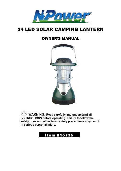
24 LED SOLAR CAMPING LANTERNOWNER’S MANUALWARNING: Read carefully and understand all INSTRUCTIONS before operating. Failure to follow thesafety rules and other basic safety precautions may result in serious personal injury.Thank you very much for choosing an NPower. product! For future reference, please complete the owner’s record below:Model: _______________ Purchase Date: _______________Save the receipt, warranty and these instructions. It is important that you read the entire manual to become familiar with this product before you begin using it.This lantern is designed for certain applications only. Northern Tool + Equipment cannot be responsible for issues arising from modification. We strongly recommend this lantern is not modified and/or used for any application other than that for which it was designed. If you have any questions relative to a particular application, DO NOT use the lantern until you have first contacted Northern Tool + Equipment to determine if it can or should be performed on the product.For technical questions please call 1-800-222-5381.INTENDED USEThe Solar Camping Lantern is designed for recreational and household activities, emergencies, and medical work.TECHNICAL SPECIFICATIONS & PACKING LISTItem DescriptionBattery 6V, 4Ah Rechargeable BatteryLight Source 24 Super Bright LEDsSolar Panel 6V 3 WattCharging Time 8 Hours (Full Sunlight)GENERAL SAFETY RULESWARNING: Read and understand all instructions. Failure to follow all instructions listed below may result in electric shock, fire and/or serious injury.WARNING:The warnings, cautions, and instructions discussed in this instruction manual cannot cover all possible conditions or situations that could occur. It must be understood by the operator that common sense and caution are factors which cannot be built into this product, but must be supplied by the operator.SAVE THESE INSTRUCTIONSPERSONAL SAFETY●Do not immerse this product in water or other liquid.●Do not put this product close to open flame.●Disconnect this product or remove its batteries before cleaning.TOOL USE AND CARE●Disconnect the power from the lantern and place the switch in the locked or off positionbefore servicing, adjusting, installing accessories or attachments, or storing. Suchpreventive safety measures reduce the risk of accidental starting.●NOTE: The lantern needs to charge in full sunlight for 8 hours to allow the rechargeablebatteries to reach maximum capacity.●If LEDs do not light, wipe both ends of the batteries with a clean and dry cloth. OPERATION1. To recharge the batteries with solar power, turn the panel to face the sunlight. Charging timeabout 8 hours (full sunlight).2. Simply push the switch to turn on.3. Use the handle to carry or hang the solar lantern.MAINTENANCEWARNING: Make sure this lantern is disconnected from its power source before attempting any maintenance, cleaning, or inspection.CLEANINGUse only soap and a damp cloth to clean your solar lantern. Many household cleaners are harmful to plastics and other insulation. Never let liquid get inside a lantern.DIAGRAM & PARTS LISTPart# Description Qty Part# Description Qty1 Hook 1 25 Screw 12 Handle 1 26 LED Panel 13 Screw 1 27 LED Fixed Stand (right) 14 Knob 1 28 LED Panel Transparent Covers 15 White Pads 1 29 Conductive Bar 16 Top Cover 1 30 Cover 17 Contact Part Fixer 1 31 Nuts 18 Red Cap 1 32 Metal Mesh Cover 19 Contact Part 1 33 Metal Bottom 110 Screw 1 34 Reflective Clip 111 Remote Control ReceiverBoard1 35 Anti-Water Plug 112 Nuts 1 36 Screw 113 Contact Part of ReceiverBoard1 37 Bottom Shell 114 Screw 1 38 Anti-Water Plug 115 Link 1 39 Charge Plate 116 Link 1 40 Nuts 117 Metal Top Cover 1 41 Screw 118 Handle Bolt 1 42 Screw 119 Top Cover 1 43 PCB Board 120 Handle Bolt 1 44 Battery 121 Nuts 1 45 Bottom Shell 122 LED Fixed Plate 1 46 12V Power Plug 123 Bolt 1 47 Charger 124 LED Fixed Stand (left) 1 1For replacement parts and technical questions, please call 1-800-222-5381.WARRANTYOne-Year Limited WarrantyDistributed byNorthern Tool + Equipment Co., Inc.Burnsville, MN 55306Made in China。
2 × 1.6 W LEDOutdoor Wall 紧急灯具说明书
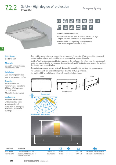
Light Source:2 × 1.6 W LED Materials:Diecast Aluminium housing Polycarbonate lens Installation:Wall mounting above exit door or along escape routes Operation:For maintained andnon-maintained operations CGLine+ (Without work-ing in AT mode)Manual test with magnet Applications:Factories, warehouses, underground car parks, workshops, tunnel Installation on emergency exits inside and outside buildingsThe durable cast Aluminium along with the high degree of protection (IP65) makes this outdoor wall unit particularly suitable for industrial areas, underground car parks and tunnels.Outdoor Wall has been developed to be mounted on the wall above the safety exits of a building both inside and outside, thanks to the special design which allows 90° installation and ensures the uniform illumination level required by law.The optical asymmetric lens are optimally designed to spread light in corridors and escape routes.For application with low ambient temperature down to -20°C, e.g. outdoors, the Outdoor LED is available also with a self-regulating battery heater.Outdoor LED light coverageh 2,5 m5 lx 7,5 m1 lx 12 m160m m184mm40071354879Outdoor Wall 1-8h CGLine+ H 9.2 VA/9.3 W225lm1 - 3 - 8 h3.7V / 4AhMaintained / Non-Maintained(with battery heater)• For indoor and outdoor use• Robust construction from Aluminium diecast and high impact resistant cover made of polycarbonate • Optional with self-regulating battery heater for use at low temperature down to -20°COutdoor Wall7.2.2210LIGHTING SOLUTIONS 7Emergency lightingSafety - High degree of protection。
华立电子 LED ceiling 照明系列商品说明书
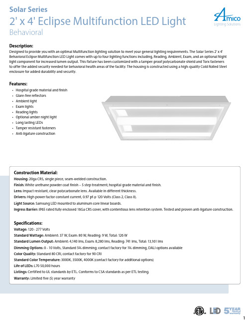
1Construction Material:Housing: 20ga CRS, single piece, seam-welded construction.Finish: White urethane powder coat finish – 5 step treatment; hospital grade material and finish.Lens: Impact resistant, clear polycarbonate lens. Available in different thickness.Drivers: High power factor constant current, 0.97 pf @ 120 Volts (Class 2, Class II).Light Source: Samsung LED mounted to aluminum core linear boards.Ingress Barrier: IP65 rated fully enclosed 16Ga CRS cover, with contentious lens retention system. Tested and proven anti-ligature construction.Specifications:Voltage: 120 - 277 VoltsStandard Wattage: Ambient: 37 W, Exam: 80 W, Reading: 9 W, Total: 126 WStandard Lumen Output: Ambient: 4,140 lms, Exam: 8,280 lms, Reading: 741 lms, Total: 13,161 lmsDimming Options: 0 - 10 Volts, Standard 5% dimming; contact factory for 1% dimming, DALI options available Color Quality: Standard 80 CRI, contact factory for 90 CRIStandard Color Temperature: 3000K, 3500K, 4000K (contact factory for additional options)Life of LEDs: L70 50,000 hoursListings: Certified to UL standards by ETL. Conforms to CSA standards as per ETL testing.Warranty: Limited five (5) year warrantyDescription:Designed to provide you with an optimal Multifunction lighting solution to meet your general lighting requirements. The Solar Series 2' x 4' Behavioral Eclipse Multifunction LED Light comes with up to four lighting functions including, Reading, Ambient, Exam, and an optional Night light component for increased lumen output. This fixture has been customized with a tamper-proof polycarbonate shield and Torx fasteners to offer the added security needed for behavioral health areas of the facility. The housing is constructed using a high-quality Cold Rolled Steel enclosure for added durability and security.Features:• Hospital grade material and finish • Glare-free reflectors • Ambient light • Exam lights • Reading lights• Optional amber night light • Long lasting LEDs• Tamper resistant fasteners •Anti-ligature constructionL SEC24Ordering Guide:Temperature& Lens TypeL-SEC24120AL11Reading (standard lms),Ambient (standard lms),Exam (standard lms)L303000KA 80 CRI F Flange Mount 000No Switch(provided by others)VRAVandal Resistant;0.118" Clear Polycarbonate 277AL12Reading (standard lms),Ambient (standard lms),Exam (high lms)L353500K B 90 CRI G Grid Mount LVC Low Voltage Controller VRBVandal Resistant;0.177" Clear Polycarbonate *Consultfactory for 347 V requirementAL21Reading (standard lms),Ambient (high lms),Exam (standard lms)L404000K LVDLow Voltage Controller with Dimming VRCVandal Resistant;0.220" Clear Polycarbonate AL22Reading (standard lms),Ambient (high lms),Exam (high lms)***Consult factory for additional optionsLMS LightMasterwithout Dimming VRDVandal Resistant;0.354" Clear Polycarbonate **Consult factory for custom light output options.LMD LightMaster with DimmingVNA Vandal Resistant & Night Light;0.118" Clear Polycarbonate VNB Vandal Resistant & Night Light;0.177" Clear Polycarbonate VNC Vandal Resistant & Night Light;0.220" Clear Polycarbonate Vandal Resistant & Night Light;For Example: L-SEC24-120-AL11-L30-B-G-LVC-VRDSolar Behavioral Eclipse Series 2' x 4',120 Volts, Reading (standard lms)/Ambient (standard lms)/Exam (standard lms), 3000 Kelvin, 90 CRI, Grid Mount, Vandal Resistant;0.354" Clear PolycarbonateOrdering Information:。
JC23354WOP 表面浴室灯说明书

300
JC23354WOP
Surface Bulkhead
• The light source of this luminaire is not replaceable: when the light source reaches its end of life, the whole of the luminaire must be replaced.
Light source: Integral LED
Important User Advice
Total circuit Wattage: 19W Luminous flux: 1600 lumens Efficacy: 84 LpcW
• It is recommended that the ambient room temperature should not exceed 30°C. • Ensure that there is adequate free air ventilation around the fitting. • The installation must not infringe on water pipes or any other electrical services.
led照明设备使用说明书
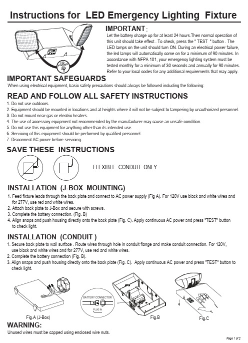
Instructions for LED Emergency Lighting FixtureIMPORTANT:READ AND FOLLOW ALL SAFETY INSTRUCTIONSSAVE THESE INSTRUCTIONSFLEXIBLE CONDUIT ONLYINSTALLATION (J-BOX MOUNTING)INSTALLATION (CONDUIT )WARNING:Let the battery charge up for at least 24 hours.Then normal operation ofthis unit should take effect . To check, press the " TEST " button . TheLED lamps on the unit should turn ON. During an electrical power failure,the led lamps will automatically come on for a minimum of 90 minutes. Inaccordance with NFPA 101, your emergency lighting system must betested monthly for a minimum of 30 seconds and annually for 90 minutes.Refer to your local codes for any additional requirements that may apply. When using electrical equipment, basic safety precautions should always be followed including the following:1. Do not use outdoors.2. Equipment should be mounted in locations and at heights where it will not be subject to tampering by unauthorized personnel.3. Do not mount near gas or electric heaters.4. The use of accessory equipment not recommended by the manufacturer may cause an unsafe condition.5. Do not use this equipment for anything other than its intended use.6. Servicing of this equipment should be performed by qualified personnel.7. Disconnect AC power before servicing.1. Feed fixture leads through the back plate and connect to AC power supply (Fig A). For 120V use black and white wires and for 277V, use red and white wires.2. Attach back plate to J-Box and secure with screws.3. Complete the battery connection. (Fig. B)4. Align snaps and push housing directly onto the back plate (Fig. C). Apply continuous AC power and press "TEST" buttonto check light.1. Secure back plate to wall surface . Route wires through hole in conduit flange and make conduit connection. For 120V,use black and white wires and for 277V, use red and white wires.2. Complete the battery connection (Fig. B).3. Align snaps and push housing directly onto the back plate (Fig. C). Apply continuous AC power and press "TEST" button to check light.Unused wires must be capped using enclosed wire nuts.Fig.A (J-Box)Page 1 of 2OPERATIONWIRING DIAGRAMREGULARREMOTE CAPABLE1. During an electrical power failure, the LED lamps will automatically come on for a minimum of 90 minutes.2. To test, depress the "TEST" switch. The emergency LED lamps will illuminate. When the switch is released, the lamps will go off.READYREADYNote:Use 18-22 AWG stranded wire to connect remote lamp heads.Page 2 of 2SELF‐DIAGNOSTICS TESTING:1)IntroductionOnce the unit is properly installed according to the Installation instruction sheet and AC power is supplied, the EXIT will come ON. The dual‐color LED indicator will also come ON, automatically initiating the self‐diagnostic test function. The LED indicator points out the current unit status. A STEADY GREEN on the LED indicator indicates a normal service; BLINKING GREEN indicates that the unit is in testing mode; GREEN/RED FLASHING indicates that the battery is charging; RED (STEADY and BLINKING) would indicate a fault or a service alert. Refer to section 3 – Fault Indication for more details. The LED indicator would be OFF when the unit is in Emergency mode.2)Self – Diagnostic ServiceThe self‐diagnostic function is factory preset without any field adjustment. The automatic self‐diagnostic feature serves the following tests –a.On‐line real time monitoring of battery and lamps: Identifies battery charging, disconnection and failure along with lampfailure.b.Self‐testing and a 30‐second discharge once every 30 days (conforming to NFPA code requirements), after AC power hasbeen supplied for a minimum of 24 hours.c.Self‐testing and a 30‐minute discharge once every 180 days, after AC power has been supplied for a minimum of 24 hours.d.Self‐testing and a 90‐minute discharge once every 365 days (conforming to NFPA code requirements), after AC power hasbeen supplied for a minimum of 24 hours.3)Fault IndicationFunction LED IndicationUnit is in normal mode STEADY GreenBattery Disconnected STEADY RedBattery Recharge Red and Green (flashing alternatively)Battery Recharge Failure* FLASHING RedBattery Failure** Red BLINKING ‘2’ timesLAMP Failure Red BLINKING ‘4’ timesRemote LAMP Failure Red BLINKING ‘5’ times* A battery recharge failure will come up if the battery is NOT able to recharge within the 24hrs charging time** A battery failure will come up if the battery is NOT able to operate the lamps for the period of a discharge test4)Manual TestingThis unit also provides for manual testing by pushing the test switch in a specific pattern. The different patterns and the resulting tests are listed in the table below.ACTION REACTION AND LED INDICATIONPush test button once (within 2 seconds) 30‐second test; FLASHING GreenPush test button ‘2’ times (within 2 seconds) 30‐minute test; Green BLINKING ‘2’ timesPush test button ‘3’ times (within 2 seconds) 90‐minute test; Green BLINKING ‘3’ timesPush & Hold test button (3‐5 seconds) System InterruptionPush & Hold test button (more than 6 seconds) System Reset5)OperationDuring an electrical power failure, the lamps will automatically come ON for a minimum of 90 minutes. To test this unit, the battery needs to be charged initially for 2 hours before depressing the test switch (to do manual test). On pressing the test switch, the Lamps will illuminate. The Lamps will turn OFF after 30‐sec /30‐min /90‐min depending on the number of times the switch has been pressed.。
LP-30D01 说明书 V1.0
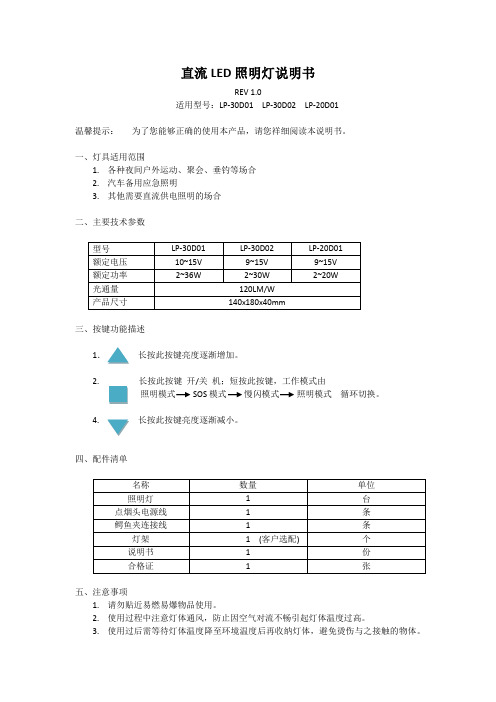
直流LED照明灯说明书
REV 1.0
适用型号:LP-30D01 LP-30D02 LP-20D01
温馨提示:为了您能够正确的使用本产品,请您祥细阅读本说明书。
一、灯具适用范围
1.各种夜间户外运动、聚会、垂钓等场合
2.汽车备用应急照明
3.其他需要直流供电照明的场合
二、主要技术参数
三、按键功能描述
1.长按此按键亮度逐渐增加。
2. 长按此按键开/关机;短按此按键,工作模式由
照明模式SOS模式慢闪模式照明模式循环切换。
4.长按此按键亮度逐渐减小。
四、配件清单
五、注意事项
1.请勿贴近易燃易爆物品使用。
2.使用过程中注意灯体通风,防止因空气对流不畅引起灯体温度过高。
3.使用过后需等待灯体温度降至环境温度后再收纳灯体,避免烫伤与之接触的物体。
中环华祥 TYD220 24-RLT14P1 型 LED 庭院灯 使用说明书
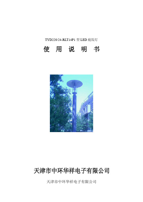
TYD220/24-RLT14P1型LED庭院灯使用说明书天津市中环华祥电子有限公司前言:尊敬的客户:感谢您选择使用我公司研制生产的TYD220/24-RLT14P1型庭院灯产品。
本手册将为您提供TYD220/24-RLT14P1型庭院灯的光学性能及安装,使用,运输时的注意事项。
请在安装使用前详细阅读本手册。
如有任何疑问请与我公司或代理商接洽。
我们将竭诚为您服务!联系方式:天津开发区微电子工业区微七路五号邮编:300085电话:022—23886658传真:022—23886625网址:1、安全警告1)不要自行拆解灯具,以免造成灯具安全防护等级降低产生次生故障。
2)灯具安装处,远离热源,振动源。
3)确认安装牢固,姿态标准。
4)注意电源线与电网连接顺序,N,L连接牢固可靠!接地线正确可靠连接。
5)确认产品表示范围与电网情况符合。
6)严禁强腐蚀性化学药品接触灯具任何部位。
7)注意防范强电磁场,防范雷电感应和雷击。
2、光学性能灯具光通量:1690lm最大光强值:375cd色温:5300K中心光强值:130cd使用寿命:30000H3、配光曲线4、环境要求1)使用环境户外安装电网电压:220V±10%环境温度:-25℃—50℃相对湿度:≤70%2)储藏环境温度:-30℃—65℃湿度:≤70%通风、无腐蚀性气体影响的场所3)运输环境本产品运输时应有必须的包装物,应避免雨、雪的直接淋袭,避免剧烈的颠簸及机械撞击,搬运时小心放置。
5、灯具安装1)产品配置清单名称规格数量备注灯具主体TYD220/24-RLT14P1型庭院灯 1使用说明书 12)安装方法(1)检查灯具主体、灯罩,电源盖板各处有无冲击痕迹,各处螺丝无松动。
松动请紧固。
(2)先安装灯头,电源线顺到灯杆里,用紧定螺钉将灯头与灯杆端部固定牢靠。
(3)打开电源盖,将顺下的电源线的正负极与电源板的接线排的正负极相连接(不得错接)。
进线与电源板的N、L、G分别连接准确。
- 1、下载文档前请自行甄别文档内容的完整性,平台不提供额外的编辑、内容补充、找答案等附加服务。
- 2、"仅部分预览"的文档,不可在线预览部分如存在完整性等问题,可反馈申请退款(可完整预览的文档不适用该条件!)。
- 3、如文档侵犯您的权益,请联系客服反馈,我们会尽快为您处理(人工客服工作时间:9:00-18:30)。
点阵屏雨棚灯使用说明书
一、概述
雨棚信号灯安装在每一车道上方的遮棚上,每一车道安装一对雨棚信号灯,分为前向信号灯和后向信号灯。
点阵屏雨棚灯适用于在车道迎车流行驶方向的遮棚上方安装,称为前向信号灯。
此产品包含组合信号灯(可分别显示红色(用×表示)、绿色(用↓表示)两种行车信号)和汉字显示区。
根据型号不同,雨棚信号灯可显示4或2个汉字,采用通用的串口RS323方式控制显示内容。
产品外观如图所示:
二、技术指标
1、雨棚信号灯灯箱尺寸:
(1)1565×600×80mm(宽×高×厚)
(2)2525×600×80mm(宽×高×厚)
组合信号灯显示尺寸:600×600mm
汉字显示区显示尺寸:
(1)(两个汉字)959.1×479.1mm
(2)(四个汉字)1918.2×479.1mm
2、输入信号电压:220 V AC ±15%
3、输入信号电流:信号灯绿色:0.10A/220V AC
信号灯红色:0.15A/220V AC
汉字显示点阵:1.047A/220V AC
4、工作环境温度:-30~65℃
5、工作环境湿度:< 95%
6、可视距离:≥300米
7、MTBF:50000小时
8、MTTR:﹤0.5小时
9、信号灯红色LED亮度> 8000cd/平方米
信号灯绿色LED亮度> 10000cd/平方米
汉字显示点阵LED亮度> 6000cd/平方米
10、超高亮度红色LED光源:直径26mm,由4个超高亮度红色LED组成
11、超高亮度绿色LED光源:直径26mm,由3个超高亮度绿色LED组成
12、半角功率角≥30°
三、安装及使用
1.安装
雨棚灯的顶部有四个固定孔,可根据实际情况使用抱箍将其安装在收费雨棚的顶部。
安装时确保安装牢靠,接线正确。
2.接线
(1)点阵屏雨棚灯的组合信号灯
点阵屏雨棚灯的组合信号灯分为红叉“╳”和绿箭头“↙”两种状态,其控制电源为灯箱右下角的1号线(如图-S),1号线为4芯线,分为棕、蓝、黑、黄四种颜色。
其中棕色线为红叉的控制火线,蓝色线为绿箭头的控制火线,黑色线为公共零线,黄色线为接地保护线。
将其接在车道控制柜(或车道机)内对应的接线端子上,即可控制组合信号灯的显示状态。
(2)点阵屏雨棚灯的点阵显示屏
点阵显示屏根据型号不同,可显示2个或4个24*24点阵的汉字,内容涵盖国标的任何汉字、字母、数字及符号,采用RS323串口控制,波特率设定为9600。
点阵显示屏的电源线为灯箱右下角的2号线(如图-S)。
2号线为3芯线,分为棕、蓝、黄三种颜色。
其中棕色线接交流220V电源的火线“L”,蓝色线接交流220V电源的零线“N”,黄色线接交流220V电源的保护地“”。
点阵显示屏的控制线为灯箱右下角的3号线(如图-S)。
3号线为3芯线,分为棕、蓝、黄三种颜色。
其中棕色线接车道工控机串口的3脚“RXD”,蓝色线接车道工控机串口的2脚“TXD”,黄色线接车道工控机串口的5脚“GND”。
设备主
题正面
1号线
3号线
2号线
1号线-4芯-组合信号灯电源线
2号线-3芯-点阵显示屏电源线
3号线-3芯-点阵显示屏串口控制线
图-S:点阵屏雨棚灯线束说明
3.使用
接通电源后,组合信号灯的显示状态由其车道机通过组合信号灯的电源线控制,点阵显示屏的显示内容由车道工控机的串孔控制,点阵显示屏断电再重新上点后的显示内容为断电前显示内容。
四、通信协议:
1、43包头
2 、44 包尾
3、命令字:01 显示命令,此命令储存,重新上电既显示该命令内容。
02 关闭显示。
03 清屏,既清除存储显示内容。
例如:
43 01 20 20 20 20 BE FC BE AF 44
(十六进制)
显示:军警
43 01 BE FC BE AF B3 B5 B5 C0 44
(十六进制)
显示:军警车道
43 01 BE FC BE AF D7 A8 D3 C3 44
(十六进制)
显示:军警专用
43 01 20 20 20 20 BF CD A3 B1 44
显示:客1
43 01 20 20 20 20 BB F5 A3 B1 44
显示:货1
43 02 44 (十六进制)
关闭显示
43 03 44 (十六进制)
清除显示内容。
数字(0-9)区位码表
0:区位码(A3B0)
1:区位码(A3B1)
2:区位码(A3B2)
3:区位码(A3B3)
4:区位码(A3B4)
5:区位码(A3B5)
6:区位码(A3B6)
7:区位码(A3B7)
8:区位码(A3B8)
9:区位码(A3B9)
五、常见故障处理及日常维护
1、 定期维护
雨棚灯应三个月维护一次,维护项目包括: ● 红叉和绿箭头能否正常切换检查 ● 接线是否轻松、接地是否可靠检查 ● 灯箱固定是否有松动检查
2、 维护方法
● 用布擦拭机箱上灰尘
● 通过切换车道开闭,检查红叉和绿箭头切换状况 ● 通过串口发送各种命令检查点阵显示屏的显示 ● 用兆殴表测量其接地电阻 ● 用扳手紧固箱体固定螺丝
3、异常现象及排除方法:
非正常损坏、非质量故障不在保修范围之内。
现 象
判断
调整方法
灯全部不亮,用万用表检查接线端子零、火线之间若无220
供电线路坏
检查供电线
路 灯全部不亮,用万用表检查接线端子零、火线之间,若有220V 电压 电源或保险坏
更换电源或 保险管 红叉和绿箭头不能正常切换
控制线路坏
检查控制线
路 红叉和绿箭头不能正常切换(控制线路正常)
雨棚灯坏 返修 点阵屏不亮 点阵屏没有上电
重新上电 不能通信
串口坏
更换串口。
