Powermill后置处理2
powermill后处理修改方法...

powermill后处理修改方法(PowerMILL post-processingmodification method)Machine fanucom -- -- post-processing file headerDefine word TN ---------------------------- defined fields;Address letter = "TOOL TYPE:-" - defines the return value of the fieldAddress width = 13 defines character widthField width = 25 defines the width of the word returned End define end definitionThe define format (/ G6, S, T, M2, L, P, D, E, H, O) M1 is defined in the form of theAddress width = 1------------ defines character width Address width = 1------------ defines character widthField width = 2 - definition of return word widthExponent width = 0 - width indexScale factor = 1 - scale factor: value multiplied by 1 Scale divisor = 1 - scale factor: value divided by 1Leave a space before the word "tape position = 1-----------"Print position = 1 - print positionSign = none----- is used without the need for G code and feed rateSign = if negative only identifies negative coordinatesSign = always, if needed + / -Not permanent - does not require line numberNot modal - only when changes need to repeat the word for modal. (modal).Typically, the G code is X, Y, and Z are coordinates of modal,But the I, J, and K codes that are usually used by the center are usually not, so they are not modalMetric formats - MetricLeading zeros = false - leading 0Trailing zeros = true - Guide 0Decimal point = false --- does not need a decimal pointDecimal places = 2 - 2 decimal pointsImperial formats - InchWord order===================== word orderWord order = (OP, N, G1, G2, G5, G3, G4, etc)Word order = (+, G6, G7, X, Y, Z, B, C)Word order = (+, I, J, K, R, D, S, T)Word order = (+, H, M1, M2, MS, MSG, EM, Q)Word order = (+ Q1, Z2, R2, ID, F)Word order = (+, TN, TD, TR, DY, MT, YR, PM)The third paragraph of define keys is the definition keyBlocknumber = N - defined programPreparatory function = G1 - defines the ready function instructionsAux function = M1 - definition of auxiliary function instructionX feedrate not used X -- definition of feed rate instructionY feedrate not used Y -- definition of feed rate instructionZ, feedrate, not, used -- define the Z feed rate instructionsCircle, angle, not, used -- circumferential angleX coordinate = X -- -- -- defines the X coordinate axis Y coordinate = Y -- -- -- defines the Y coordinate axis Z coordinate = Z -- -- -- defines the Z coordinate axis Key i = I - X - I bond axis vector definitionKey J = J - - Y axis vector JKey K = K - Z - K bond axis vector definitionFeedrate = F - - - defines feed rate instructionsFeedrate per revolution = F--- defines the feed rate instruction per turnSpindle = S -- -- -- defining spindle instructions chair number = t - - 定义刀具指令 ------ translated dwell not used ----------- 不使用循环停留 cycle--------------- 定义暂停时间键值 dwell = xlength = h ------------ 定义刀具长度补偿指令 chairthe chair ------------ 定义刀具半径补偿指令 radius = ddrill peck depth = q1 - - - - 钻孔的啄钻深度drill hole depth = z2 定义钻孔深度...----------- 定义安全平面高度 clearplane = r2.--------- 定义注释的开始符 message start = msmessage itself ----------- 定义注释的结束符 = emopskip = op - - - - --------- 定义跳段符号radius... -------- 键定义半径 r = rprogram id = id... - - - 定义程序号azimuth axis = b - - - - --------- 在多轴加工中, 定义方位轴elevation axis = c --------- 在多轴加工中, 定义仰角轴3rd rotation axis = zero... 在多轴加工中, 定义第三旋转轴not used (% 领导不使用 leaderthe x vector not used x矢量不使用 meddra system organ class y vector not used y矢量不使用 meddra system organ classz vector not used z矢量不使用 meddra system organ classerror 错误不使用 not used "define yourselfdefine ------------- --------- 定义指令值 codesrapid = 0 = = = = = g1 ---------- -------- 快速点定位linear = g1 = = = = = "1 直线插补circle cw = = = = = = g1 2 ------------- 顺圆插补circle ccw = = = = = = g1 3 ------------ 逆圆插补dwell = = = = ------------------- 暂停、准确停止 g6 4.the g3 xy plane = = = = = = = 17 平面 ------------- xyzy plane = = = = = = g3 19 --------- - - - - 平面 plastic tray xz plane = 18 = = = = = g3 平面 ------------- zxcompensation off = 40 = = ------ translated 取消刀具半径补偿g2compensation is left = = = = = 刀具半径左补偿 g2 41 compensation is right = g2 42 = = = 刀具半径右补偿imperial data = 20 = = = = = g4 --------- 英寸输入metric data 21 = = = = = g4 ---------- 毫米输入 = = =absolute data = = = = = ----------- g5 90 指定绝对坐标编程incremental data = = = = = -------- g5 91 指定增量坐标编程from = = = = = = g3 54 ------------------- 制定工作坐标系feedrate per minute not used = = = = = = 每分钟进给feedrate per revoluti not used = = = = = 每转进给spindle rpm not used 每分钟转速 meddra system organ classconstant surface speed not used 恒定的表面速度 ------ translateddrill = = = = = ------------------- g4 81 钻孔循环锪镗循环break the g4 chip = = = = --------------- 钻孔循环或反镗循环82deep drill = = = = = = g4 83 = ----------- 深孔钻循环tap = = = = = = g4 84 = = ------------------ 攻丝循环bore 85 = = = 1 = g4 --------------- 镗孔循环 = = = =the g4 bore 2 = = = = = = = 86 --------------- 镗孔循环the g4 bore 3 = = = = = = = 87 (% 背镗循环孔4 = 88 ====== ----------------镗孔循环G4孔5 = 89 ====== ----------------镗孔循环G4端钻= G4 80 ====== ----------固定循环取消宏开始不习惯======= ---------宏程序模态调用不使用===== -------------宏程序模态调用取消宏结束宏调用不使用======== ---------宏程序调用周期收回= G6 99 = = ------------固定循环返回到R点刀具长度偏置= = = = = ----- G3 43正向刀具长度补偿不使用========插补方式-------------花键花键停止0 = = = = = M1 ---------------------程序停止选择停止= M1 1 ===== ----------------选择停止在CW = M1 3 ===== -----------主轴正转主轴在CCW = M1 4 ===== ----------主轴逆转主轴主轴停止= M1 5 ===== -------------主轴停止自旋对CW = ----------------- M1 13冷却液旋转逆时针= ---------------- M1 14冷却液旋转冷却液= M1 5 = = = = --------冷却液关换刀= M1 6 ===== ------------自动换刀冷却液雾= = = = ----------雾状冷却液M1 7冷却液对M1 8 = = = = = ---------------冷却液开洪水= M1 8 = ------------冷却液开冷却剂(喷出)冷却液= M1 9 ===== -------------冷却液关夹在不使用------ -------------主轴锁紧不要用--------------------主轴锁紧不使用夹磁带结束= M1 2 ===== -------------程序结束结束程序= M1 30 ===== ------------程序结束1不使用----------------变速范围1不使用档2不使用----------------变速范围2不使用档3不使用----------------变速范围3不使用档恒定的速度不-----持续的轮廓速度不使用轮廓2不使用恒定轮廓速度----持续的轮廓速度2不使用字钻不------------------钻孔指令不使用字断屑不使用------------不使用断屑深不------------------孔深不使用字字不------------------冷却水不使用水龙头字孔1不使用---------------孔1不使用字孔2未使用字孔3未使用字孔4未使用字孔5未使用自来水不习惯-------------冷却液不使用冷却剂不使用====== -----------刚性攻丝刚性攻丝螺旋钻不------------螺旋钻孔螺旋收缩不------螺旋钻孔不使用钻最后定义===========================定义变量打印头=“Delcam后处理器”= = = =定义打印标题机器名称=“fanuc6m 1.2版”= = =机器名点==================================小数点零=“0”=============================零磁带头= 1 =======================纸带标题整数6 = 2 ====================== = = =定义冷却液开(M07、M08)的输出方式,此变量共有三个选项--0:在后处理时遇到相关指令时输出;1:在下一段中单独输出;2:在下一段中和坐标移动一起输出。
powermill后处理制作
powermill后处理制作
DUCTpost ,powermill编程软件后处理DUCTpost 为我们提供了很多
的控制器,供我们使用,我们只需要在里面选择我们所需要的后处理,就能制作出我们需要的后处理
来,我们跟本没有必要花时间写下新控制器的全部信息,DUCTpost 使用保存的50个最常用机床控
制器的信息,这些信息可通过编写option 选项文件修改。
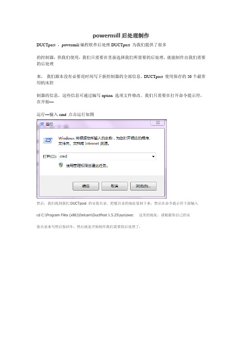
我们只需要在打开命令提示符,在开始—
运行—输入cmd 点击运行如图
然后,我们找到我们DUCTpost 的安装目录,把根目录的地址复制下来,然后在命令提示符下面输入
cd C:\Program Files (x86)\Delcam\DuctPost 1.5.25\sys\exec 这里的地址,请根据你自己的安
装目录来写然后按回车,然后就是开始制作我们需要的后处理了,
在命令提示符里面输入ductpost -w fanuc >c:\myfanuc.opt 然后按回车如图
那么这里的红色的就是们的控制器的名称,这里可以跟据你自己的需要自己选择,蓝色的就是
重新命名为myfanuc.opt存在C:\ 那么我可以到C盘根目录下面去找myfanuc.opt 这就是我们新做的后处理了,当我们powermill刀路编好之后,需要处理程序的时候,就可以选择这个后处
理文件进行后处理了。
文章来源:Powermill视频教程/。
PowerMILL后处理的分析说明

PowerMILL 後處理對於後處理格式,一般的用戶有三個層次的需求:一、powermill自帶的後處理中有適合自己機床要求的,不過要修改、增刪些代碼。
二、沒有適合的,需要改寫後處理。
三、機床的代碼格式完全與普通G代碼格式不同,需建全新的後處理。
本文只針對1、2種需求來進行講解,至於第三種則是高級篇的範疇了(哈哈,其實我也不知道,還沒做過呢)現在開始準備工作:1、以不同的控制器試著處理幾個G代碼檔出來,然後和自己機床的代碼進行比較,選一個最接近自己的。
2、打開ductpost\dp-index.html,準備有問題就看幫助。
3、運行:ductpost -w [控制器類型] > [控制器類型].opt ,從而生成OPT檔,這個選最接近你機床的控制器。
如:ductpost -w hurco > hurco.opt 。
這時就可以用文本編輯器來打開這個opt檔了:1、程式頭、程式尾的改寫:這個在以下的定義裏面:define block tape start********************end definedefine block tape end*******************end define你可以根據自己的需要添加,如:define block tape start"%"N ; "G17G90G80G40G49"end definedefine block tape endN ; "M05"N ; "M30"end define不過注意這種引號方法優點是簡單明瞭,但控制器只是把它當字元處理,而不能以模態存在,具體可參見其他說明。
2、是否需要N行號?%:0001N10G28G91X0Y0Z0N30T1M6N40G0G90X-25.Y-40.S800 M3如這上面的N10、N30、N40,另外行號的起始、增量、最大都可以定義。
powermill后处理修改方法[整理]
![powermill后处理修改方法[整理]](https://img.taocdn.com/s3/m/7e027da43c1ec5da50e270ff.png)
powermill 后办理改正方法[ 整理 ]powermill后办理改正方法machine fanucom ——————后办理文件头define word TN ---------------------------- 定义字段 ;address letter = "TOOL TYPE :- " ----- 定义字段的返回值address width = 13 定义字符宽度field width = 25 定义返回字的宽度end define结束定义define format ( / G6 S T M1 M2 L P D E H O ) 第二段是定义字符的格式address width = 1------------ 定义字符宽度address width = 1------------定义字符宽度field width = 2 ------------- 定义返回字的宽度exponent width = 0 ---------- 指数的宽度scale factor = 1 -------------比率因子: 值乘以 1scale divisor = 1 ------------ 比率因子 : 值被 1 除tape position = 1----------- 字前留一个空格print position = 1 ----------- 打印地点sign = none----- 用于不需要G 代码和进给率sign = if negative 仅表记负坐标sign = always 假如需要+ / - 号not permanent -------- 不需要行号not modal ------------ 仅当改变时需要重复的字为modal 。
( 模态 )。
往常 G 代码和 X, Y和Z为坐标为modal,但圆心往常使用的I, J, K代码往常不是,所以它们为not modal .metric formats --------------- 公制leading zeros = false ---------前导0 trailing zeros = true ---------- 后导0 decimal point = false ------不需要小数点decimal places = 2 -------- 小数点后 2 imperial formats------------- 英制word order=====================语序 word order = ( OP N G1 G2 G3 G4G5 ) word order = ( + G6 G7 X Y Z B C ) word order = ( + I J K R D S T )word order = ( + H M1 M2 MS msg EM Q ) word order = ( + Q1 Z2 R2 ID F )word order = ( + TN TD TR DY MT YR PM )define keys第三段是定义键值blocknumber = N—————定义程序段号preparatory function = G1——定义准备功能指令aux function = M1 ------------- 定义协助功能指令x feedrate not used ---------- 定义X 进给率指令y feedrate not used ---------- 定义Y 进给率指令z feedrate not used —— ------ 定义Z 进给率指令circle angle not used ————圆周角度x coordinate = X —————- --- 定义X 坐标轴y coordinate = Y —————---- 定义Y 坐标轴z coordinate = Z —————--- 定义Z 坐标轴key i = I —————--------- -定义X 轴矢量I 键key j = J —————---------- 定义Y 轴矢量Jkey k = K —————---------- 定义Z 轴矢量K 键feedrate = F —————------- 定义进给率指令feedrate perrevolution = F--- 定义每转进给率指令spindle = S ——————----- 定义主轴指令tool number = T ——————-- 定义刀具指令cycle dwell not used----------- 不使用循环逗留dwell = X —————---------- 定义暂停时间键值tool length = H —— ---------- 定义刀具长度赔偿指令tool radius = D —— ---------- 定义刀具半径赔偿指令drill peck depth = Q1 ————钻孔的啄钻深度 drill hole depth =Z2 ———— - 定义钻孔深度 clearplane = R2———-------- 定义安全平面高度message start = MS —— ------- 定义说明的开始符message end = EM —— --------- 定义说明的结束符opskip = OP ———— --------- 定义跳段符号 radius = R ————— -- ------ 定义半径R 键program id = ID —————--- 定义程序号azimuth axis = B ---- --------- 在多轴加工中,定义方向轴elevation axis = C —— ------- 在多轴加工中,定义仰角轴3rd rotation axis = null ----- 在多轴加工中,定义第三旋转轴leader not used---------------- 领导不使用x vector not used--------------X 矢量不使用y vector not used--------------Y 矢量不使用z vectornot used--------------Z 矢量不使用error not used----------------- 错误不使用end definedefine codes ------------- --------- 定义指令值rapid = G1 0 =====---------- -------- 迅速点定位linear = G1 1 ===== ----------------- 直线插补circle cw = G1 2=====------------- 顺圆插补circle ccw = G1 3 =====------------ 逆圆插补dwell = G6 4 === ------------------- 暂停、正确停止xy plane = G3 17 ======------------- XY 平面zy plane = G3 19 =====--------- ---- YZ 平面xz plane = G3 18 =====------------- ZX 平面compensation off = G2 40 == ------ 撤消刀具半径赔偿compensation on left = G2 41 ==== 刀具半径左赔偿compensation on right = G2 42 === 刀具半径右赔偿imperial data = G4 20 ===== --------- 英寸输入 metric data = G4 21=======---------- 毫米输入 absolute data = G5 90 ====----------- 指定绝对坐标编程incremental data = G5 91 ====-------- 指定增量坐标编程from = G3 54 ===== ------------------- 拟订工作坐标系feedrate per minute not used ====== 每分钟进给feedrate per revoluti not used ===== 每转进给 spindle rpm not used -------------- 每分钟转速constant surface speed not used------ 恒定的表面速度drill = G4 81 ==== ------------------- 钻孔循环锪镗循环break chip = G4 82 === --------------- 钻孔循环或反镗循环deep drill = G4 83 ======----------- 深孔钻循环tap = G4 84 ======= ------------------ 攻丝循环 bore 1 = G4 85=======--------------- 镗孔循环 bore 2 = G4 86 ======--------------- 镗孔循环 bore 3 = G4 87 ======---------------- 背镗循环bore 4 = G4 88 ======---------------- 镗孔循环 bore 5 = G4 89 ====== ---------------- 镗孔循环 end of drill = G4 80 ======---------- 固定循环撤消macro start not used ======= --------- 宏程序模态调用macro end not used =====------------- 宏程序模态调用撤消macro call not used ========--------- 宏程序调用cycle retract = G6 99 ==------------ 固定循环返回到 R 点tool length offset = G3 43 ====----- 正向刀具长度赔偿spline not used ========------------- spline 插补方式stop = M1 0 ====--------------------- 程序停止opt stop = M1 1=====---------------- 选择停止spindle on cw = M1 3 =====----------- 主轴正转spindle on ccw = M1 4 =====---------- 主轴逆转spindle off = M1 5=====------------- 主轴停止 spin coolant on cw =----------------- M1 13 spincoolant on ccw =---------------- M1 14 spin coolant off = M1 5====-------- 冷却液关change tool = M1 6 ===== ------------ 自动换刀coolant on mist = M1 7 === ---------- 雾状冷却液coolant on = M1 8 ====--------------- 冷却液开coolant on flood = M18 =------------ 冷却液开 ( 喷出 )coolant off = M1 9 ===== ------------- 冷却液关clamp on not used ------ ------------- 主轴锁紧clamp off not used-------------------- 主轴锁紧不使用end of tape = M1 2 =====------------- 程序结束end of prog = M1 30===== ------------ 程序结束gear range 1 not used---------------- 变速范围1不使用gear range 2 not used---------------- 变速范围 2 不使用gear range 3 not used---------------- 变速范围 3 不使用constant contour speed not used----- 连续的轮廓速度不使用constant contour speed 2 not used---- 连续的轮廓速度 2 不使用word drill not used------------------ 钻孔指令不使用word break chip not used------------ 不使用断屑word deep not used------------------ 孔深不使用word tap not used------------------ 冷却水不使用word bore 1 not used--------------- 孔1不使用word bore 2 not usedword bore 3 not usedword bore 4 not usedword bore 5 not usedcoolant on tap not used------------- 冷却液不使用rigid tap not used ======----------- 刚性攻丝helical drill not used------------ 螺旋钻孔helical retract drill not used------ 螺旋钻孔不使用end define===========================定义变量 Print header ="Delcam Post processor"====定义打印标题machine name = "Fanuc6m version 1.2" ===机器名point ==================================小数点zero = "0" ============================= 零 tape headers = 1=======================纸带标题integer 6 = 2====================== ===定义冷却液开(M07、M08 )的输出方式,此变量共有三个选项——0 :在后办理时碰到有关指令时输出; 1 :在下一段中独自输出;2 : 在下一段中和坐标挪动一同输出。
[新版]powermill后处理
![[新版]powermill后处理](https://img.taocdn.com/s3/m/0b1ba3f7192e45361166f517.png)
[新版]powermill后处理PowerMILL后处理修改本教程是偶在实际使用中的PowerMILL后处理文件修改知识的积累,其中有部分修改案例来源于帮助文件,在此仅以文字和图片的形式把他记录下来与初学者共同分享。
一、完整的后处理文件介绍一个完整的后处理文件通常有:定义字符段、定义字符格式段、定义键值段、定义指令值段、变量定义、程序格式段等部分组成。
下面我们先来看一个比较完整的后处理文件,并把它分为数段,把需要修改的地方做个必要的解释:machine fanucom ——————后处理文件头=========================== 第一部分是定义字符段==============================define word TNaddress letter = "TOOL TYPE:- "address width = 13field width = 25end define具体解释:define word TN ——————————————定义字段;address letter = "TOOL TYPE:- " —————定义字段的返回值,比如在后处理文件里有“MS=C ; TN ToolType ; EM =C”,而在写程式的时候选用的是端铣刀,那么在CNC程式里就会有(TOOL TYPE:- ENDMILL);address width = 13 ———————————定义字符宽度,如上"TOOL TYPE:- ",从T开始算起一共13位,包括空格;field width = 25 ———————————定义返回字的宽度,如上"ENDMILL",如果fieldwidth = 2,那"TOOL TYPE:- "就返回EN;如果field width = 25,那"TOOL TYPE:- "就返回ENDMILL。
[新版]powermill后处理
[新版]powermill后处理PowerMILL后处理修改本教程是偶在实际使用中的PowerMILL后处理文件修改知识的积累,其中有部分修改案例来源于帮助文件,在此仅以文字和图片的形式把他记录下来与初学者共同分享。
一、完整的后处理文件介绍一个完整的后处理文件通常有:定义字符段、定义字符格式段、定义键值段、定义指令值段、变量定义、程序格式段等部分组成。
下面我们先来看一个比较完整的后处理文件,并把它分为数段,把需要修改的地方做个必要的解释:machine fanucom ——————后处理文件头=========================== 第一部分是定义字符段==============================define word TNaddress letter = "TOOL TYPE:- "address width = 13field width = 25end define具体解释:define word TN ——————————————定义字段;address letter = "TOOL TYPE:- " —————定义字段的返回值,比如在后处理文件里有“MS=C ; TN ToolType ; EM =C”,而在写程式的时候选用的是端铣刀,那么在CNC程式里就会有(TOOL TYPE:- ENDMILL);address width = 13 ———————————定义字符宽度,如上"TOOL TYPE:- ",从T开始算起一共13位,包括空格;field width = 25 ———————————定义返回字的宽度,如上"ENDMILL",如果fieldwidth = 2,那"TOOL TYPE:- "就返回EN;如果field width = 25,那"TOOL TYPE:- "就返回ENDMILL。
powermill后处理修改参考
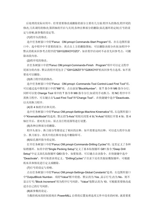
后处理的实际应用中,经常需要修改或删除的部分主要有几方面:程序头的修改;程序尾的修改;刀具调用的修改;第四轴的开启与关闭;各种注释部分的删除;钻孔循环的定制;行号的设定与省略;新参数的设定等。
(1)程序头的修改。
选中任务树窗口中的"Fanuc OM.pmopt Commands-Start Program"项,在右边图形窗口中,选中程序中不需要的部分,再点击上方的删除图标,可以删除该部分内容;如程序中默认的机床回参考点程序段"G91G28XOYOZO",如在程序启动时不必首先回参考点,可删除该段内容。
(2)程序尾的修改。
在任务树窗口中的"Fanuc OM.pmopt-Commands-Finish Program"项中可以定义程序尾部分的内容。
默认的程序尾包含了"G91G28Z0"和"G28XOY0"机床回参考点选项,如不需要也可以删除。
(3)换刀程序段的修改。
选中任务树窗口中的"Fanuc OM.pmopt -Commands-Tool Control-Load First Tool"项,可以通过选中图形窗口中的"M6"项,点击添加"BlockNumber",使T指令和M6指令分行;同样可以使Change Tool项中的T指令和M6指令分行;如采用手动换刀,则NC程序中不需换刀程序,可右键点击"Load First Tool"和"Change Tool",在快捷键中选中"Deactivate,以关闭换刀程序。
(4)第4轴的开启和关闭。
选中任务树窗口中的"Fanuc OM.pmopt-Settings-Machine Kinematics"项,右边图形窗口中"KinematicModel"的选项,默认的"3-Axis"项则关闭第4轴;"4-Axis"项则打开第4轴,第4轴打开后,需对其方向、原点及行程范围等进行设置。
powermill后处理入门与应用实例精析 概述及解释说明
powermill后处理入门与应用实例精析概述及解释说明1. 引言1.1 概述:本文旨在深入探讨PowerMill后处理的基础知识和应用实例,并解释其在制造领域中的重要性。
PowerMill是一款专业的计算机辅助制造(CAM)软件,广泛应用于数控编程和加工路径生成。
1.2 文章结构:本文按照以下结构来进行论述和说明:- 引言:介绍文章的目的、概述和文章结构。
- PowerMill后处理入门:详细阐述了PowerMill的概述、后处理定义和作用,以及后处理流程的简介。
- PowerMill后处理应用实例精析:通过三个实例,详细说明了如何生成NC程序代码、如何修复刀轨迹中的错误与瑕疵,以及如何优化加工效率和质量。
- 结论:对全文进行总结,回顾主要内容和立场,并展望未来PowerMill后处理的发展方向,并提出建议。
1.3 目的:本文旨在为读者提供关于PowerMill后处理方面的全面指导。
通过阐明PowerMill后处理入门知识和应用示例,读者将能够更好地理解并应用此功能来提高其制造过程中的效率和质量。
通过对文章内容进行总结并展望未来的发展,读者将能够更好地规划和使用PowerMill后处理技术。
2. PowerMill后处理入门:2.1 PowerMill概述:PowerMill是一款专业的数控加工软件,广泛应用于制造业中。
它拥有强大的后处理功能,可以将CAD模型转化为可执行的数控(NC)程序代码,从而实现机床上的自动加工。
PowerMill的后处理功能可以根据机床类型、刀具路径和加工要求等参数生成符合标准的NC代码。
2.2 后处理的定义和作用:后处理是指将由CAD/CAM软件生成的刀具路径数据转化为特定机床所需的NC程序代码。
在数控加工过程中,后处理起着至关重要的作用。
它不仅决定了刀具路径是否顺畅、安全有效,还确保了最终零件的精度和质量。
因此,良好的后处理是保证数控加工成功的必备条件之一。
2.3 后处理流程简介:PowerMill后处理流程通常包括以下步骤:1. 导入CAD模型:首先需要将设计好的三维CAD模型导入PowerMill软件中进行进一步操作。
适合北京精雕机床使用的POWERMILL后处理

适合北京精雕机床使用的POWERMILL后处理machine fanucdefine word Kaddress letter = "K"end definedefine word Raddress letter = "R"end definedefine word R2address letter = "R"end definedefine word Qaddress letter = "Q"end definedefine word Aaddress letter = "A"end definedefine word Baddress letter = "B"end definedefine word Caddress letter = "C" end definedefine word U address letter = "U" end definedefine word V address letter = "V" end definedefine word W address letter = "W" end definedefine word Z2 address letter = "Z" end definedefine word F address letter = "F" end definedefine word S address letter = "S" end definedefine word T address letter = "T" end definedefine word M1 address letter = "M" end definedefine word M2 address letter = "M" end definedefine word L address letter = "L" end definedefine word P address letter = "P" end definedefine word D address letter = "D" end definedefine word E address letter = "E" end definedefine word H address letter = "H" end definedefine word Oaddress letter = "O" end definedefine word MS address letter = "("end definedefine word EM address letter = ")"end definedefine word OP address letter = "/"end definedefine word ID address letter = "O" end definedefine word Q1 address letter = "Q" end definedefine word null address letter = ""end definedefine word MT address letter = "Date:-" address width = 7end definedefine word DYaddress letter = "/"address width = 1field width = 2end definedefine word YRaddress letter = "/"address width = 1field width = 2end definedefine word HRaddress letter = " Time:- " address width = 8field width = 2end definedefine word MNaddress letter = ":"address width = 1field width = 2end definedefine word PNaddress letter = "Program Name: " address width = 15end definedefine word TPaddress letter = "ToolPath Name: " address width = 17field width = 25end definedefine word TDaddress letter = " D="address width = 4scale factor = 2end definedefine word TIPRaddress letter = " R="address width = 4end definedefine word TLaddress letter = " L="address width = 4end definedefine word TYaddress letter = "Tool Type: " address width = 11fieldwidth = 20end definedefine format ( TD TIPR TL )modalfield width = 15metric formatdecimal point = truedecimal places = 2leading zeros = falsetrailing zeros = trueend definedefine format ( / G6 S T M1 M2 L P D E H O ) address width = 1field width = 2exponent width = 0scale factor = 1scale divisor = 1tape position = 1print position = 1sign = nonenot permanentnot modalmetric formatsleading zeros = falsetrailing zeros = truedecimal point = falsedecimal places = 0imperial formatsleading zeros = falsetrailing zeros = truedecimal point = falsedecimal places = 0end definedefine format ( N )address width = 1field width = 4exponent width = 0scale factor = 1scale divisor = 1tape position = 1print position = 1sign = nonenot permanentnot modalmetric formatsleading zeros = falsetrailing zeros = truedecimal point = falsedecimal places = 0imperial formatsleading zeros = falsetrailing zeros = truedecimal point = falsedecimal places = 0end definedefine format ( G1 G2 G3 G4 G5 G7 ) address width = 1field width = 2exponent width = 0scale factor = 1scale divisor = 1tape position = 1print position = 1sign = nonenot permanentmodalmetric formatsleading zeros = true trailing zeros = true decimal point = false decimal places = 0 imperial formatsleading zeros = false trailing zeros = true decimal point = false decimal places = 0end definedefine format ( X Y Z R B C ) address width = 1field width = 8exponent width = 0scale factor = 1scale divisor = 1tape position = 1print position = 1sign = if negativenot permanent modalmetric formats leading zeros = false trailing zeros = false decimal point = tru edecimal places = 4 imperial formats leading zeros = false trailing zeros = false decimal point = true decimal places = 4 end definedefine format ( I J K ) address width = 1 field width = 8 exponent width = 0 scale factor = -1 scale divisor = 1 tape position = 1 print position = 1 sign = if negative not permanentnot modalmetric formats leading zeros = false trailing zeros = false decimal point = truedecimal places = 4 imperial formats leading zeros = false trailing zeros = false decimal point = true decimal places = 4end definedefine format ( R2 Z2 Q1 ) address width = 1field width = 8 exponent width = 0 scale factor = 1scale divisor = 1tape position = 1print position = 1sign = if negativenot permanentnot modalmetric formatsleading zeros = false trailing zeros = false decimal point = true decimal places = 3 imperial formats leading zeros = false trailing zeros = false decimal point = true decimal places = 4end definedefine format ( Q A U V W ) address width = 1field width = 2exponent width = 0scale factor = 1scale divisor = 1tape position = 1print position = 1sign = if negativenot permanentnot modalmetric formatsleading zeros = false trailing zeros = true decimal point = false decimal places = 0 imperial formatsleading zeros = false trailing zeros = true decimal point = false decimal places = 0end definedefine format ( F ) address width = 1field width = 2exponent width = 0scale factor = 1scale divisor = 1tape position = 1print position = 1sign = if negativenot permanentmodalmetric formatsleading zeros = false trailing zeros = true decimal point = false decimal places = 0imperial formatsleading zeros = false trailing zeros = true decimal point = false decimal places = 0end definedefine format ( MS EM OP ) address width = 1field width = 0exponent width = 0scale factor = 1scale divisor = 1tape position = 1print position = 1sign = nonenot permanentnot modalmetric formatsleading zeros = false trailing zeros = true decimal point = false decimal places = 0 imperial formats leading zeros = false trailing zeros = true decimal point = false decimal places = 0 end definedefine format ( ID ) address width = 1 field width = 4 exponent width = 0 scale factor = 1 scale divisor = 1 tape position = 0 print position = 1 sign = nonenot permanentnot modalmetric formats leading zeros = true trailing zeros = true decimal point = false decimal places = 0 imperial formats leading zeros = true trailing zeros = truedecimal point = false decimal places = 0 end definedefine format ( null ) address width = 0 field width = 0 exponent width = 0 scale factor = 1 scale divisor = 1 tape position = 0 print position = 1 sign = nonenot permanentnot modalmetric formats leading zeros = false trailing zeros = true decimal point = false decimal places = 0 imperial formats leading zeros = false trailing zeros = true decimal point = false decimal places = 0 end define# linked words define format ( MS ) link to EMend defineword order = ( OP N G1 G2 G3 G4 G5 )word order = ( + G6 G7 X Y Z B C )word order = ( + I J K R D S T )word order = ( + H M1 M2 MS msg EM Q ) word order = ( + Q1 Z2 R2 ID F )word order = ( + PN TP MT DY YR HR MN EM ) word order = ( + TY TD TIPR TL )define keysblocknumber = Npreparatory function= G1aux function = M1x feedrate not usedy feedrate not usedz feedrate not usedcircle angle not usedx coordinate = Xy coordinate = Yz coordinate = Zkey i = Ikey j = Jkey k = Kfeedrate = Ffeedrate per revolution = Fspindle = Stool number = Tcycle dwell not used dwell = Xtool length = Htool radius = Ddrill peck depth = Q1 drill hole depth = Z2 clearplane = R2 message start = MS message end = EM opskip = OPradius = Rprogram id = ID azimuth axis = B elevation axis = C3rd rotation axis = null leader not usedx vector not usedy vector not usedz vector not used error not usedend definedefine codesrapid = G1 0linear = G1 1circle cw = G1 2 circle ccw = G1 3 dwell = G6 4xy plane = G3 17zy plane = G3 19xz plane = G3 18 compensation off = G2 40 compensation on left = G2 41 compensation on right = G2 42 imperial data = G4 20metric data = G4 21absolute data = G5 90 incremental data = G5 91from = G3 54feedrate per minute not used feedrate per revolution not used spindle rpm not used constant surface speed not used drill = G4 81break chip = G4 82deep drill = G4 83tap = G4 84bore 1 = G4 85bore 2 = G4 86bore 3 = G4 87bore 4 =G4 88bore 5 = G4 89end of drill = G4 80macro start not usedmacro end not usedmacro call not usedcycle retract = G6 99tool length offset = G6 43 spline not usedstop = M1 0opt stop = M1 1spindle on cw = M1 3spindle on cc = M1 4spindle off = M1 5spin coolant on cw = M1 13spin coolant on ccw = M1 14spin coolant off = M1 5change tool = M1 6coolant on mist = M1 7coolant on = M1 8coolant on flood = M1 8coolant off = M1 9clamp on not usedclamp off not usedend of tape = M1 2end of prog = M1 30gear range 1 not usedgear range 2 not usedgear range 3 not usedconstant contour speed not used constant contour speed 2 not used word drill not usedword break chip not usedword deep not usedword tap not usedword bore 1 not usedword bore 2 not usedword bore 3 not usedword bore 4 not usedword bore 5 not usedazimuth clamp off not usedcoolant on tap not usedrigid tap not usedhelical drill not usedhelical retract drill not useddeep drill 2 not usedazimuth clamp on not usedcoolant on air not usedcoolant on double not usedcoolant on through not usedend define# print header = "Delcam Postprocessor" # machine name = "jingdiao version 1.0" point = "."zero = "0"tape headers = 1integer 6 = 2integer 7 = 1integer 10 = 2integer 11 = 1integer 12 = 1tool reset coordinates = 3cycle output = 1integer 20 = 1block start = 10block increment= 10split move = 0integer 26 = 1program id start = 1integer 34 = 3integer 35 = 1integer 36 = 1integer 37 = 2rapid feed code = 0maximum block number = 0 maximum tape blocks = 0 minimum tape blocks = 0 segment type = 0counter start = 0counter increment = 0tape split retract distance = -999 workplane angle convention = 1 multiaxis coordinate transform = true message output = falseblock order = truetlo output = truetape split on tool change = falsefull circle = falseincremental centre = truego home output = falseuse partid = trueuse progid = truespindle x motion = falsespindle y motion = falsespindle z motion = truespindle w motion = falsespindle azimuth rotation = falsespindle elevation rotation = false linearise multiaxis moves = trueuse hole top in cycles = false retract at angular limit = false unwind at tool change = false suppress xy arc = falsesuppress xz arc = falsesuppress yz arc = falsetransform workplane origin = false previous multax rapid style = false minimise multiaxis retractions = false contact point based feedrate = false multiaxis toollength used = truefull rewind at limit = falseuse fiveaxis always = false workplane origin shift = true expand helical drilling cycles = false linearise first move = trueoutput rapids in multiaxis = false use toolpath safe heights = false clear modal words for cycles = true use true safez in cycles = falsetool change before linearised = true knot vector type = noneunits = inputcoordinates = absoluteazimuth axis units = degrees azimuth axis direction = positive elevation axis units = degrees elevation axis direction = positivespline type = noneworkplane angles = noneoption file units = noneretract and reconfigure style = nonemaximum feedrate = 6000.0000minimum feedrate = 10.0000rapid feedrate = 9999.0000maximum tape length = 0.0000plunge threshold angle = 0.0000maximum segment = 0.0000diameter = 1.0000withdrawal amount = 50.0000arc radius limit = 10000.0000retraction threshhold angle = 360.0000arc minimum radius = 0.00100azimuth axis parameters = ( 0 0 0 0 0 0 )azimuth centre = ( 0 0 0 )elevation axis parameters = ( 0 0 0 0 0 0 )elevation centre = ( 0 0 0 )pcs origin = ( 0 0 0 0 0 0 )linear axis limits = ( -99999 999999 -99999 999999 -99999 999999 )rotary axis limits = ( -99999 999999 -99999 999999 999 1 ) move safe angles = ( 0 0 0 0 )define block tape start"%"ID ProgID"(" ; PN JobName ; " )""(" ; MT Month ; DY Day ; YR Year ; HR Hour ; MN Minute ; " )"# N ; MS =C ; TN T oolType ; EM =C# N ; MS =C ; TD T oolRadius[ToolNum] ; EM =C# N ; MS =C ; TR T oolRadius[ToolNum] ; EM =C# N ; G2 91 ; G6 28 ; X 0 ; Y 0 ; Z 0N ; compensation off ; G6 49 ; xy plane ; G4 80 ; G5 90# N ; G5 90 ; G1 0 ; Z FromZend definedefine block tape endN ; M1 05# N ; M1 09N ; G6 28 ; G5 91 ; Z 0 ; Z =C# N ; G6 49 ; H 0 ;# N ; G6 28 ; X 0 ; Y 0 ; X =C ; Y =CN ; M1 30end definedefine block go home preambleend definedefine block tool change first"(" ; TP ToolPathName ; " )"N ; G5 91 ; G6 28 ; Z 0 ; Z =CN ; OP ; T ToolNum ; change tool"(" ; TY ToolType ; TD ToolRadius[ToolNum] ; TIPR TipRadius[T oolNum] ; TL ToolLength[ToolNum] ; " )"N ; G3 54 ; G5 90 ; G3 =C ; G5 =C ;end definedefine block tool changeN ; M1 05N ; M1 09N ; M1 01"(" ; TP ToolPathName ; " )"N ; G5 91 ; G6 28 ; Z 0 ; Z =C# N ; H 0 ; G6 49# N ; G6 28 ; X 0 ; Y 0 ; X =C ; Y =CN ; T ToolNumber ; change tool"(" ; TY ToolType ; TD ToolRadius[ToolNum] ; TIPR TipRadius[T oolNum] ; TL ToolLength[ToolNum] ; " )"N ; G1 0 ; G5 90 ; G3 54 ; G1 =C ; G5 =C ; G3 =C ;end definedefine block tool change clearend definedefine block go home z moveend definedefine block go home xy moveend definedefine block move fromend definedefine block move circleN ; G1 ; G2 ; G3 ; X ; Y ; Z ; I ; J ; K ; F ; D end definedefine block move linear# if ( feedrate => srat )# N ; G1 0 ; X ; Y ; Z ; M1 ; M2# elseN ; G1 ; G2 ; G3 ; D ; X ; Y ; Z ; F ; M1 ; M2 # end ifend definedefine block move rapidN ; G1 ; G2 ; G3 ; G5 ; G6 ; X ; Y ; Z ; H ; S ; M1 ; M2end definedefine block move cycleN ; G4 ; G6 ; X ; Y ; Z2 ; R2 ; Q ; Q1 ; F ; M2 end definedefine block move tapN; G6 ; G4 ; X ; Y ; Z2 ; R2 ; F ; M1 ; M2end definedefine block tape segmentend definedefine block tape split start"%"ID ProgIDend definedefine block tape split endN ; G1 28 ; G6 91 ; Z 0 ; Z =CN ; H 0 ; G6 49N ; G6 28 ; X 0 ; Y 0 ; X =C ; Y =CN ; M1 30end definedefine block cycle startN ; S ; M1N ; G3 ; G5 ; M2F =C ; G4 =C ; Z2 ; R2 ; Q ; Q1 ; G6 ; end definedefine block cycle endN ; G4 80end definedefine block tape split moveend definedefine block move splineend definedefine block datum shiftend definedefine block multiaxis transitionend definedefine block special record end defineend。
PowerMILLopt后处理修改方法

PowerMILLopt后处理修改方法machine fanucom ——————后处理文件头define word TN ---------------------------- 定义字段;address letter = "TOOL TYPE :- " ----- 定义字段的返回值address width = 13 定义字符宽度field width = 25 定义返回字的宽度end define 结束定义define format ( / G6 S T M1 M2 L P D E H O ) 第二段是定义字符的格式address width = 1------------ 定义字符宽度address width = 1------------ 定义字符宽度field width = 2 ------------- 定义返回字的宽度exponent width = 0 ---------- 指数的宽度scale factor = 1 ------------- 比例因子:值乘以 1scale divisor = 1 ------------ 比例因子:值被 1 除tape position = 1----------- 字前留一个空格print position = 1 -----------打印位置sign = none----- 用于不需要 G代码和进给率sign = if negative 仅标识负坐标sign = always 如果需要 + / - 号not permanent -------- 不需要行号not modal ------------ 仅当改变时需要重复的字为modal 。
(模态)。
通常 G 代码和 X, Y 和 Z 为坐标为 modal,但圆心通常使用的 I, J, K 代码通常不是,因此它们为 not modal .metric formats --------------- 公制leading zeros = false --------- 前导 0trailing zeros = true ----------后导 0decimal point = false ------ 不需要小数点decimal places = 2 -------- 小数点后 2 imperial formats ------------- 英制word order=====================语序word order = ( OP N G1 G2 G3 G4 G5 )word order = ( + G6 G7 X Y Z B C )word order = ( + I J K R D S T )word order = ( + H M1 M2 MS msg EM Q ) word order = ( + Q1 Z2 R2 ID F )word order = ( + TN TD TR DY MT YR PM )define keys 第三段是定义键值blocknumber = N —————定义程序段号preparatory function = G1 ——定义准备功能指令aux function = M1 -------------定义辅助功能指令x feedrate not used ---------- 定义 X 进给率指令y feedrate not used ---------- 定义 Y 进给率指令z feedrate not used ——------ 定义 Z 进给率指令circle angle not used ————圆周角度x coordinate = X —————----定义 X 坐标轴y coordinate = Y —————----定义 Y 坐标轴z coordinate = Z —————--- 定义 Z 坐标轴key i = I —————---------- 定义 X 轴矢量 I 键key j = J ————— ----------定义 Y 轴矢量 J key k = K —————---------- 定义 Z 轴矢量 K 键feedrate = F —————------- 定义进给率指令feedrate per revolution = F--- 定义每转进给率指令spindle = S ——————----- 定义主轴指令tool number = T —————— --定义刀具指令cycle dwell not used-----------不使用循环停留dwell = X —————---------- 定义暂停时间键值tool length = H ——---------- 定义刀具长度补偿指令tool radius = D ——---------- 定义刀具半径补偿指令drill peck depth = Q1 ————钻孔的啄钻深度drill hole depth = Z2 ————-定义钻孔深度clearplane = R2 ———-------- 定义安全平面高度message start = MS ——------- 定义注释的开始符message end = EM ——--------- 定义注释的结束符opskip = OP ———— --------- 定义跳段符号radius = R ————— -------- 定义半径 R 键program id = ID ————— --- 定义程序号azimuth axis = B ---- ---------在多轴加工中,定义方位轴elevation axis = C ——------- 在多轴加工中,定义仰角轴3rd rotation axis = null ----- 在多轴加工中,定义第三旋转轴leader not used----------------领导不使用x vector not used--------------X矢量不使用y vector not used--------------Y矢量不使用z vector not used--------------Z矢量不使用error not used-----------------错误不使用end definedefine codes ------------- --------- 定义指令值rapid = G1 0 =====---------- -------- 快速点定位linear = G1 1 ===== ----------------- 直线插补circle cw = G1 2 =====------------- 顺圆插补circle ccw = G1 3 =====------------ 逆圆插补dwell = G6 4 === ------------------- 暂停、准确停止xy plane = G3 17 ======------------- XY 平面zy plane = G3 19 =====--------- ---- YZ 平面xz plane = G3 18 =====------------- ZX 平面compensation off = G2 40 == ------ 取消刀具半径补偿compensation on left = G2 41 ==== 刀具半径左补偿compensation on right = G2 42 === 刀具半径右补偿imperial data = G4 20 ===== --------- 英寸输入metric data = G4 21 =======---------- 毫米输入absolute data = G5 90 ====----------- 指定绝对坐标编程incremental data = G5 91 ====-------- 指定增量坐标编程from = G3 54 ===== -------------------制定工作坐标系feedrate per minute not used ====== 每分钟进给feedrate per revoluti not used ===== 每转进给spindle rpm not used -------------- 每分钟转速constant surface speed not used------ 恒定的表面速度drill = G4 81 ==== -------------------钻孔循环锪镗循环break chip = G4 82 === ---------------钻孔循环或反镗循环deep drill = G4 83 ======----------- 深孔钻循环tap = G4 84 ======= ------------------攻丝循环bore 1 = G4 85 =======--------------- 镗孔循环bore 2 = G4 86 ======--------------- 镗孔循环bore 3 = G4 87 ======---------------- 背镗循环bore 4 = G4 88 ======---------------- 镗孔循环bore 5 = G4 89 ====== ----------------镗孔循环end of drill = G4 80 ======---------- 固定循环取消macro start not used ======= ---------宏程序模态调用macro end not used =====------------- 宏程序模态调用取消macro call not used ========--------- 宏程序调用cycle retract = G6 99 ==------------ 固定循环返回到 R 点tool length offset = G3 43 ====----- 正向刀具长度补偿spline not used ========------------- spline 插补方式stop = M1 0 ====--------------------- 程序停止opt stop = M1 1 =====---------------- 选择停止spindle on cw = M1 3 =====----------- 主轴正转spindle on ccw = M1 4 =====---------- 主轴逆转spindle off = M1 5 =====------------- 主轴停止spin coolant on cw =----------------- M1 13spin coolant on ccw =---------------- M1 14spin coolant off = M1 5 ====-------- 冷却液关change tool = M1 6 ===== ------------ 自动换刀coolant on mist = M1 7 === ---------- 雾状冷却液coolant on = M1 8 ====--------------- 冷却液开coolant on flood = M1 8 =------------ 冷却液开(喷出)coolant off = M1 9 ===== -------------冷却液关clamp on not used ------ -------------主轴锁紧clamp off not used--------------------主轴锁紧不使用end of tape = M1 2 =====------------- 程序结束end of prog = M1 30 ===== ------------程序结束gear range 1 not used---------------- 变速范围1不使用gear range 2 not used---------------- 变速范围2不使用gear range 3 not used---------------- 变速范围3不使用constant contour speed not used----- 持续的轮廓速度不使用constant contour speed 2 not used----持续的轮廓速度2不使用word drill not used------------------钻孔指令不使用word break chip not used------------不使用断屑word deep not used------------------孔深不使用word tap not used------------------冷却水不使用word bore 1 not used---------------孔1不使用word bore 2 not usedword bore 3 not usedword bore 4 not usedword bore 5 not usedcoolant on tap not used-------------冷却液不使用rigid tap not used ======----------- 刚性攻丝helical drill not used ------------ 螺旋钻孔helical retract drill not used------螺旋钻孔不使用end define=========================== 定义变量Print header ="Delcam Post processor"==== 定义打印标题machine name = "Fanuc6m version 1.2" === 机器名point ================================== 小数点zero = "0" ============================= 零tape headers = 1 ======================= 纸带标题integer 6 = 2====================== === 定义冷却液开(M07 、M08 )的输出方式,此变量共有三个选项——0 :在后处理时遇到相关指令时输出;1 :在下一段中单独输出;2 :在下一段中和坐标移动一起输出。
弘法数控雕控机 POWERMILL 后处理方法
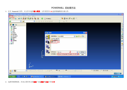
POWERMILL 后处理方法1.打开Powermill 软件,从文件中选取输入模型,文件类型为*.stl,选择要编辑的扫描文件。
2.选择顶视图观看,在显示菜单里去掉线框勾选阴影和光标下的十字
3.选择用户坐标系下的产生用户坐标系。
4.激活用户坐标系1,点击毛坯/计算/接受。
调整扫描模型与毛坯的角度和位置,摆正毛坯与扫描文件
5.调整模型的位置,在顶视图中将X轴的最大值调整为0,在左视图中将Y轴的位置设置到模型左右中间,在前视图中将Z轴的位置设置到模型的上下中间。
6.锁定X最大值和X最小值,(各减少2个单位,最大值可能会多一点。
主要是左端要过最低的截面。
)扩展2单位,计算。
7.刀具路径策略/精加工/旋转精加工。
8.刀具名称直刀(圆底刀),直径12.7(8)、长度50(40)、余量5(0)、行距5(0.4),按毛坯限界重设/直线/任意/按整圆重设/应用/接受。
9.○a快进高度/圆柱体/按安全高度重设/应用到激活刀具路径/接受。
○b开始点和结束点/毛坯中心安全高度/应用开始(结束)点/应用/接受○c切入切出和连接/连
接/在曲面上/掠过/掠过/应用连接/应用/接受。
10.产生NC程序/名称/输出文件/机床选项文件(C:/dcam/config/ducpost/FANUC15M-4A.OPTS)应用/接受。
11.将刀具路径拖到NC程序,NC程序为未激活状态,右键写入。
12.修改tap文件,删除头部小括号()内容,将尾部G28 Z0.0改为G28 X0.0。
保存。
powermill ductpost后置处理修改

DuctPost1430后置处理的修改说明指导思想:1.确定机床认同的标准代码文件;2.可使用DUCTPOST –W HEID.OPT >C:\HEID.OPT利用PM已有的3轴后置来获取数控系统的基本后置3.使用DUCTPOST标准后置产生机床的加工代码文件;4.对比两者的差异,增加自定义用户化信息,由于增加信息无条件优先,它会替代系统默认的原始信息,不断修改直到DUCTPOST产生的加工代码文件和所需标准代码文件一致;5.修改中注意备份和重命名(建议增加机床具体型号以示区别),删除用户化信息后,后置将自动还原成系统初始默认的标准后置;具体参数:1.程序行号a)如果系统不需要行号,那么重新定义批号键“N”define format ( N )not permanentend defineb)如果系统需要行号起始行号“10”,增量行号“5”,可如下定义批号键“N”block start = 10block increment = 5c)如果机床能认同的最大行号有所限制,那么可以插入下面的选项maximum block number = 5999(or whatever value required)d)需要特殊的行号的地方多半定义一些特殊技能N1000 BEGIN PGM SPECIAL MMN1000 TOOL CALL 0 Z S3000N1000 M55N1000 M3N1000 CYCL DEF 19.0 BEARBEITUNGSEBENEN1000 CYCL DEF 19.1 A0 B0 C0N10 L X0.0 Y0.0 Z150.0 B0 C0 FMAXN12 L X254.345 Y146.780 B90.0 C35.250 FMAXN14 L Z-55.70 FMAXN16 L ...........................建议采用下面的格式define word NFaddress letter = "N1000"address width = 5field width = 0end defineword order = ( + NF )define block tape startNF 0 ; " BEGIN PGM" ; ID PartID ; metric dataend definedefine block tool change firstNF 0 ; T2 0 ; " Z " ; S 3000NF 0 ; M1 55NF 0 ; M1 3NF 0 ; G4 190 ; " BEARBEITUNGSEBENE "NF 0 ; G4 191 ; A 0 ; B 0 ; C 0N ; G1 ; X FromX ; Y FromY ; Z FromZ ; B =C ; C =C ; FMAXend define2.线形移动通常线形输出的标准格式为G01 X... Y... Z... F...G01(G1)是直线命令,XYZ是绝对或增量坐标,F是进给速度3.快速移动典型的快速移动输出格式可能象这样G00 G43 X... Y... Z... S... H.... M34.圆弧运动通常线形输出的标准格式为G02(G03)X... Y... I... J... F... xy Plane ( G17 )G02(G03)X... Z... I... K... F... zx Plane ( G18 )G02(G03)Y... Z... J... K... F... yz Plane ( G19 )G2/G3代表顺圆/逆圆,X,Y,Z代表圆弧终点坐标,I,J,K代表圆心,设置如下:define codescircle cw = G1 2circle ccw = G1 3xy plane = G3 17xz plane = G3 18zy plane = G3 19end defineI,J,K表现为绝对坐标时设置为:incremental centre = falseI,J,K表现为相对坐标时设置为:incremental centre = true假如圆心坐标I,J,K符号不对(如果更改过圆心类型,一定要主义检查),可以这样改正define format ( I J K )scale factor = -1 or1end define有的机床不能输出整圆,需要将整个圆弧分为四个象限输出,此时需要作如下设定single quadrant = true圆弧可以被强制输出为直线段,可作如下设定integer 26 = 0更常用或者circle output = ( 0 1 1 1 )在ductpost1430中圆弧可以分平面强制输出为直线段,可作如下设定suppress xy arc = true default = falsesuppress zx arc = true default = falsesuppress yz arc = true default = false5.信息输出信息输出设置是个二进位选项,默认值是有信息输出,如果不需要,直接添加message output = false6.行程极限轴向移动行程限制由下面的命令行控制(缺省值):linear axis limits = ( -99999. 99999. -99999. 99999. -99999. 99999. )第一对数据控制X的正负极限行程,第二对控制Y,第三对控制Z。
Powermill三轴后处理说明
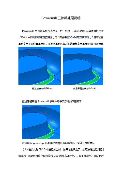
Powermill三轴后处理说明Powermill中路径连接方式中有一种“掠过”(Skim)的方式,其原理相当于JDPaint中的局部快速定位路径,与“安全平面”(Safe)的方式不同,Z轴不必抬高到安全平面位置高度处,而是抬高到区域之间的局部安全高度处,如下图所示;掠过连接方式(Skim) 安全平面连接方式(Safe)掠过路径段在Powermill系统中的表示方法如下图所示:在采用Jingdiao.opt后处理文件输出NC路径后,有以下两种情况:(1)在读入到EN3D中进行加工时,如果之前设定了【读取快速定位路径】选项后,此时掠过路径段将按照G01的方式进行走刀,如下图所示。
建议此时采用带速度加工的方式进行实际加工,这样我们在程序中设定的掠过速度才能起作用,当抬刀比较多时,可以明显的提高加工效率。
如下图所示:(2)在读入到En3D中进行加工时,如果之前没有设定【读取快速定位路径】选项,路径读入后如下图所示;此时在实际加工中在掠过路径段的起末点处将会额外地各自产生一次抬刀,这样当路径中的掠过路径段比较多时,将产生大量的抬刀路径,有时会明显降低切削加工的效率。
因此,我们在Powermill中输入NC时选择Jingdiao_skim.opt后处理文件来将掠过路径段在输出时直接就转化为G00路径段,这样有两个好处:(1)之前设定了【读取快速定位路径】选项时,如下图所示,如果用户不带程序中的速度进行实际加工,这样当抬刀比较多时,加工效率将不受影响;(2)之前未设定【读取快速定位路径】选项时,读入的路径如下图所示,实际加工时系统在路径子段的期末点自动添加抬刀路径而不会产生过多的抬刀路径;需要注意的是:采用Jingdiao_skim.opt进行后处理的前提条件是在Powermill的路径速度参数设置值中,需设定掠过速度大于其它的进给速度,否则加工时可能会产生严重的错误。
若没有这个习惯,建议采用Jingdiao.opt 后处理文件来输出NC路径,此时选择【读取快速定位路径】选项和带速度加工模式。
PowerMILL后处理修改教程
PowerMILL后处理修改教程本教程是偶在实际使用中的PowerMILL后处理文件修改知识的积累,其中有部分修改案例来源于帮助文件,在此仅以文字和图片的形式把他记录下来与初学者共同分享。
By mymould(风影爱人)一、完整的后处理文件介绍一个完整的后处理文件通常有:定义字符段、定义字符格式段、定义键值段、定义指令值段、变量定义、程序格式段等部分组成。
下面我们先来看一个比较完整的后处理文件,并把它分为数段,把需要修改的地方做个必要的解释:machine fanucom ——————后处理文件头=========================== 第一部分是定义字符段 ==============================define word TNaddress letter = "TOOL TYPE:- "address width = 13field width = 25end define具体解释:define word TN ——————————————定义字段;address letter = "TOOL TYPE:- " —————定义字段的返回值,比如在后处理文件里有“MS =C ; TN ToolType ; EM =C”,而在写程式的时候选用的是端铣刀,那么在CNC程式里就会有(TOOL TYPE:- ENDMILL);address width = 13 ———————————定义字符宽度,如上"TOOL TYPE:- ",从T开始算起一共13位,包括空格;field width = 25 ———————————定义返回字的宽度,如上"ENDMILL",如果field width = 2,那"TOOL TYPE:- "就返回EN;如果field width = 25,那"TOOL TYPE:-"就返回ENDMILL。
PowerMILL后处理修改教程
PowerMILL后处理修改教程一、完整的后处理文件介绍一个完整的后处理文件通常有:定义字符段、定义字符格式段、定义键值段、定义指令值段、变量定义、程序格式段等部分组成。
下面我们先来看一个比较完整的后处理文件,并把它分为数段,把需要修改的地方做个必要的解释:machine fanucom ——————后处理文件头============第一部分是定义字符段=================================== define word TNaddress letter = "TOOL TYPE:- "address width = 13field width = 25end define具体解释:define word TN ——————————————定义字段;address letter = "TOOL TYPE:- " —————定义字段的返回值,比如在后处理文件里有“MS =C ; TN ToolType ; EM =C”,而在写程式的时候选用的是端铣刀,那么在CNC程式里就会有(TOOL TYPE:- ENDMILL);address width = 13 ———————————定义字符宽度,如上"TOOL TYPE:- ",从T开始算起一共13位,包括空格;field width = 25 ———————————定义返回字的宽度,如上"ENDMILL",如果field width = 2,那"TOOL TYPE:- "就返回EN;如果field width = 25,那"TOOL TYPE:- "就返回ENDMILL。
end define========================== 第二段是定义字符的格式================================== define format ( / G6 S T M1 M2 L P D E H O )address width = 1field width = 2exponent width = 0scale factor = 1scale divisor = 1tape position = 0print position = 1sign = nonenot permanentnot modalmetric formatsleading zeros = falsetrailing zeros = truedecimal point = false 控制公制尺寸的前导零、后导零,小数点decimal places = 0imperial formatsleading zeros = falsetrailing zeros = truedecimal point = false 控制英制尺寸的前导零、后导零,小数点decimal places = 0end defineword order = ( OP N G1 G2 G3 G4 G5 )word order = ( + G6 G7 X Y Z B C )word order = ( + I J K R D S T )word order = ( + H M1 M2 MS msg EM Q ) 注册字符word order = ( + Q1 Z2 R2 ID F )word order = ( + TN TD TR DY MT YR PM )========================== 第三段是定义键值======================================== define keysblocknumber = N ——————定义程序段号preparatory function = G1 ———————定义准备功能指令aux function = M1 ——————定义辅助功能指令x feedrate not used —————定义X进给率指令y feedrate not used —————定义Y进给率指令z feedrate not used —————定义Z进给率指令circle angle not used —————圆周角度x coordinate = X ——————定义X坐标轴y coordinate = Y ——————定义Y坐标轴z coordinate = Z ——————定义Z坐标轴key i = I ——————定义X轴矢量I键key j = J ——————定义Y轴矢量J键key k = K ——————定义Z轴矢量K键feedrate = F ——————定义进给率指令feedrate per revolution = F ———————定义每转进给率指令spindle = S ——————定义主轴指令tool number = T ——————定义刀具指令cycle dwell not useddwell = X —————定义暂停时间键值tool length = H ——————定义刀具长度补偿指令tool radius = D ——————定义刀具半径补偿指令drill peck depth = Q1 ——————钻孔的啄钻深度drill hole depth = Z2 ——————定义钻孔深度clearplane = R2 —————定义安全平面高度message start = MS —————定义注释的开始符message end = EM ————定义注释的结束符opskip = OP ————定义跳段符号radius = R —————定义半径R键program id = ID —————定义程序号azimuth axis = B —————在多轴加工中,定义方位轴elevation axis = C —————在多轴加工中,定义仰角轴3rd rotation axis = null —————在多轴加工中,定义第三旋转轴leader not usedx vector not usedy vector not usedz vector not usederror not usedend define=============== 定义指令值======================================== define codesrapid = G1 0 ========== 快速点定位linear = G1 1 =========== 直线插补circle cw = G1 2 =========== 顺圆插补circle ccw = G1 3 ========== 逆圆插补dwell = G6 4 ========= 暂停、准确停止xy plane = G3 17 ========= XY平面zy plane = G3 19 ========= YZ平面xz plane = G3 18 ========= ZX平面compensation off = G2 40 ========== 取消刀具半径补偿compensation on left = G2 41 =========== 刀具半径左补偿compensation on right = G2 42 =========== 刀具半径右补偿imperial data = G4 20 ============ 英寸输入metric data = G4 21 ============ 毫米输入absolute data = G5 90 ============ 指定绝对坐标编程incremental data = G5 91 ============ 指定增量坐标编程from = G3 54 ========== 制定工作坐标系feedrate per minute not used ================ 每分钟进给feedrate per revolution not used ================= 每转进给spindle rpm not usedconstant surface speed not useddrill = G4 81 =========== 钻孔循环锪镗循环break chip = G4 82 =========== 钻孔循环或反镗循环deep drill = G4 83 ============ 深孔钻循环tap = G4 84 ========== 攻丝循环bore 1 = G4 85 ========== 镗孔循环bore 2 = G4 86 ========== 镗孔循环bore 3 = G4 87 ========== 背镗循环bore 4 = G4 88 ========== 镗孔循环bore 5 = G4 89 ========== 镗孔循环end of drill = G4 80 ============= 固定循环取消macro start not used ============ 宏程序模态调用macro end not used =========== 宏程序模态调用取消macro call not used ============ 宏程序调用cycle retract = G6 99 ========== 固定循环返回到R点tool length offset = G3 43 =========== 正向刀具长度补偿spline not used ======== spline插补方式stop = M1 0 ==== 程序停止opt stop = M1 1 ===== 选择停止spindle on cw = M1 3 ===== 主轴正转spindle on ccw = M1 4 ===== 主轴逆转spindle off = M1 5 ===== 主轴停止spin coolant on cw = M1 13spin coolant on ccw = M1 14spin coolant off = M1 5 ====== 冷却液关change tool = M1 6 ====== 自动换刀coolant on mist = M1 7 ===== 雾状冷却液coolant on = M1 8 ==== 冷却液开coolant on flood = M1 8 ===== 冷却液开(喷出)coolant off = M1 9 ===== 冷却液关clamp on not usedclamp off not usedend of tape = M1 2 ===== 程序结束end of prog = M1 30 ===== 程序结束gear range 1 not usedgear range 2 not usedgear range 3 not usedconstant contour speed not usedconstant contour speed 2 not usedword drill not usedword break chip not usedword deep not usedword tap not usedword bore 1 not usedword bore 2 not usedword bore 3 not usedword bore 4 not usedword bore 5 not usedcoolant on tap not usedrigid tap not used ====== 刚性攻丝helical drill not usedhelical retract drill not usedend define================ 定义变量====================================== print header = "Delcam Postprocessor" ================== 定义打印标题machine name = "Fanuc6m version 1.2" ========= 机器名point = "." ================================ 小数点zero = "0" =============================== 零tape headers = 1 ============================== 纸带标题(integer 6 、integer 7):定义coolant output(冷却液输出)integer 6 = 2 ============== 定义冷却液开(M07、M08)的输出方式,此变量共有三个选项——0:在后处理时遇到相关指令时输出;1:在下一段中单独输出;2、在下一段中和坐标移动一起输出。
PowerMILL的后处理应用技巧
???选中任务树窗口中的"FanucOM.pmopt-Settings-MachineKinematics"项,右边图形窗口中"KinematicModel"的选项,默认的"3-Axis"项则关闭第4轴;"4-Axis"项则打开第4轴,第4轴打开后,需对其方向、原点及行程范围等进行设置。
PowerMILL的后处理应用技巧
1引言
???PowerMILL是一种专业的数控加工自动编程软件,由英国Delcam公司研制开发。从PowerMILL的使用来看,PowerMILL可以说是世界上功能最强大、加工策略最丰富的数控加工编程软件系统之一,同时也是CAM软件技术最具代表性的、增长率最快的加工软件。它实现了CAM系统与CAD系统的分离,可以更充分发挥CAM和CAD各系统的优势,可在网络下完成一体化集成,所以更能适应工程化的要求。其广泛应用于航空航天、汽车、船舶、家电以及模具等行业,尤其对各种塑料模、压铸模、橡胶膜、锻模、冲压模等具有明显的优势.
???PowerMILL默认每次启动后会自动运行的宏"pmuser.mac"保存在程序安装目录下"X:1ProgramFiles\Delcam\PowerMILL6008\lib\macro"。其中"X"代表PowerMILL的安装根目录。这里可以采用宏将固定不变的NC程序后处理相关设置步骤记录下来,实现程序启动后自动加载默认的后处理定制。如:希望每次NC程序后处理默认的机床选项文件为系统自带的"Fanuc.pmopt",默认的NC程序后缀名改为".nc",所有NC程序的存放文件夹为"E:\Temp\FANUC"。具体实现步骤如下:
PowerMILL的后处理应用技巧

P o w e r M I L L的后处理应用技巧The manuscript can be freely edited and modified1引言PowerMILL是一种专业的数控加工自动编程软件;由英国Delcam公司研制开发..从PowerMILL的使用来看;PowerMILL可以说是世界上功能最强大、加工策略最丰富的数控加工编程软件系统之一;同时也是CAM软件技术最具代表性的、增长率最快的加工软件..它实现了CAM系统与CAD系统的分离;可以更充分发挥CAM和CAD各系统的优势;可在网络下完成一体化集成;所以更能适应工程化的要求..其广泛应用于航空航天、汽车、船舶、家电以及模具等行业;尤其对各种塑料模、压铸模、橡胶膜、锻模、冲压模等具有明显的优势.软件的数控自动编程主要是软件经过刀位等自动计算产生加工刀具路径文件;但刀路文件并不是数控程序..需要从加工刀具路径文件中提取相关的加工信息;并根据指定数控机床的特点及要求进行分析、判断和处理;最终形成数控机床能直接识别的数控程序;这就是数控加工的后置处理..本文针对PowerMILL自动编程软件后处理方面的技巧进行探讨..2 PowerMILL后处理使用技巧在PowerMILL生成刀具路径后;提供了两种后处理方法:NC程序和PM-Post后处理.2.1 NC程序NC程序模块存在于PowerMILL浏览器中;如图1所示;没有工具栏也没有快捷图标;只能通过"NC程序"菜单和NC程序对象菜单进行参数设置..NC程序生成的主要步骤如下:1右键单击产生的每个刀具路径;在弹出的菜单、中选择"产生独立的NC程序";或者右键单击PowerMILL浏览器中的"NC程序";在弹出的菜单路径;在弹出的菜单中选择"增加到NC程序"选项..2右键单击生成的每个NC程序;在弹出的菜单中选择"写人";或者右键单击Poirer112ILL浏览器中的"NC程序";在弹出的菜单中选择"全部写人"选项..2.2 PM-Post后处理PM-Post是Delcam提供的专用后处理模块;其后处理操作步骤如下:1在PowerMILL的"选项"中将NC程序输出文件类型改成"刀位";输出后缀名为cut的刀具路径文件..2启动PM-Post进人PostProcessor模块;如图2所示;分别添加NC程序格式选项文件Optionfiles和第一步产生的刀具路径文件CLDATAGles.3右键单击某个刀具路径文件;在弹出的菜单中选择Process选项;实现该刀具路径文件的NC程序的输出..可以看出;NC程序方法简单;当程序后处理设置为固定无需改动时;只需要选择相应的后处理选项文件;即可快速生成所需的NC程序代码..这种方法适用于单位设备固定统一;软件后处理对应性较强的情况..PM-Post方法不但可以生成所需的NC程序;还可以通过PM-Post中的Editor模块对NC程序格式选项文件进行设置;有利于生成更加简洁高效的NC程序代码..这种方法比较适合单位设备的种类型号较多;且自动数控编程由工艺组统一负责;然后再根据设备分配情况生成NC加工程序等场合..3PowerMILL后处理设置技巧早期的PowerMILL后处理程序DuctPost以及其它数控编程软件提供的后处理程序大部分都是基于纯文本文档;用户可通过文本编辑器修改这些文件..该文件结构主要有注释、定义变量类型、定义使用格式、常量赋值、定义问题、字符串列表、自定义单节及系统问题等部分..最新的PowerMILL后处理程序PM-Post基于图形窗口和对话框;使后处理选项文件的设置变得直观、明了..PM-Post的格式选项文件的修改在Editor模块中进行;如图3所示..下面以Fanuc系统为例;给出常用后处理设置的方法:为保留系统自带的Fanuc后处理文件;我们在修改前先将该文件另存为FanucOM.pmopt;并在此基础上进行修改..启动PM-Post;进人Editor模块;点击"LoadOptionfile"快捷图标选中并加载Fanuc.pmopt后处理文件;然后另存为FanucOM.pmopt..后处理的实际应用中;经常需要修改或删除的部分主要有几方面:程序头的修改;程序尾的修改;刀具调用的修改;第四轴的开启与关闭;各种注释部分的删除;钻孔循环的定制;行号的设定与省略;新参数的设定等..1程序头的修改..选中任务树窗口中的"Fanuc OM.pmoptCommands-StartProgram"项;在右边图形窗口中;选中程序中不需要的部分;再点击上方的删除图标;可以删除该部分内容;如程序中默认的机床回参考点程序段"G91G28XOYOZO";如在程序启动时不必首先回参考点;可删除该段内容..2程序尾的修改..在任务树窗口中的"FanucOM.pmopt-Commands-Finish Program"项中可以定义程序尾部分的内容..默认的程序尾包含了"G91G28Z0"和"G28XOY0"机床回参考点选项;如不需要也可以删除..3换刀程序段的修改..选中任务树窗口中的"Fanuc OM.pmopt-Commands-ToolControl-LoadFirstTool"项;可以通过选中图形窗口中的"M6"项;点击添加"BlockNumber";使T指令和M6指令分行;同样可以使ChangeTool项中的T指令和M6指令分行;如采用手动换刀;则NC程序中不需换刀程序;可右键点击"LoadFirstTool"和"ChangeTool";在快捷键中选中"Deactivate;以关闭换刀程序..4第4轴的开启和关闭..选中任务树窗口中的"FanucOM.pmopt-Settings-MachineKinematics"项;右边图形窗口中"KinematicModel"的选项;默认的"3-Axis"项则关闭第4轴;"4-Axis"项则打开第4轴;第4轴打开后;需对其方向、原点及行程范围等进行设置..5各种注释部分的删除..程序头部分、换刀部分等都设定了相应的注释;如不需要这些注释;可以进人程序头部分、换刀部分;将其中的注释内容选中删除即可..6钻孔循环指令的定制..打开任务树窗口中的"FanucOM.pmopt-Commands-DrillingCycles"项;这里定义了各种钻销循环..如其中的"SinglePeckingSetup"定义了基本钻削循环G81指令;"DeepDrillSetup"中定义深孔钻削循环G83指令..如要取消;可右键点击该指令;在快捷键中选中"Deactivate";即可取消该项定义.."DrillingCycles"子目录下还有其他钻镬削循环;可根据机床具体情况进行定义或删除..7行号的设定与省略..点击任务树窗口中的"FanucOM.pmopt-Settings-GlobalConstants"选项;右边图形窗口中"OutputBlockNumber;项的"Value"框中的值;默认的为Yes;显示行号;改为No;则不显示行号;"BlockIncrement"项为程序行号间距;"Value"值默认的为10;可根据需要修改成适合自己的行号间距..8新参数的设定..当数控机床的控制系统在PowerMILL自带的后置处理选项文件中没有的时候;就需要重新定义新的控制系统选项文件..如需专门定义各种常用G;M;F;S代码以及坐标表示等;可在"Fanuc OM.pmopt-Parameters"项中进行..如;需修改快进G代码G00;可双击"Fanuc OM.pmopt-Parameters-General-MotionMode";在弹出的对话框中对"RAP状态项后面的"Value"值进行修改;还可以在对话框上半部分的"Prefix"修改快进指令的前缀+G;如需修改冷却模式的M代码;可双击"FanucOM.pmopt-Parameters-General-CoolantMode";在弹出的对话框中进行相应修改;主轴转速可在"FanucOM.pmopt-Parameters-General-SpindleSpeed"中进行..4基于宏的后处理快速定制在PowerMILL的应用过程中;一般软件自动编程所对应的机床控制系统都是固定不变的;如果每次启动都对NC程序的后处理进行相同的设置则显得较麻烦..利用PowerMILL自带的宏的编制;可以实现每次软件启动后自动进行NC程序后处理的默认定制;加速NC程序代码的生成;简化NC程序生成过程..PowerMILL默认每次启动后会自动运行的宏"pmuser.mac"保存在程序安装目录下"X:1ProgramFiles\Delcam\PowerMILL6008\lib\macro"..其中"X"代表PowerMILL的安装根目录..这里可以采用宏将固定不变的NC程序后处理相关设置步骤记录下来;实现程序启动后自动加载默认的后处理定制..如:希望每次NC程序后处理默认的机床选项文件为系统自带的"Fanuc.pmopt";默认的NC程序后缀名改为".nc";所有NC程序的存放文件夹为"E:\Temp\FANUC"..具体实现步骤如下:1启动PowerMILL后;右键单击浏览器最下端的"宏";点选"记录";在弹出的"选取记录宏文件"的对话框中设置好宏的保存目录和文件名;程序开始将后面的每一步操作都记录在宏文件中..2打开菜单"工具-选项";在弹出的"选项表格"对话框中的"NC程序"标签下;"文件类型"选择"NC程序";"选项文件"选择"Fanuc";后缀名"tap"改为+nc;;路径输人"FANUC".3右键点击浏览器中的"NC程序";选"参数选择";在弹出的"NC参数选择"对话框中的"输出目录"中输人"E:/1emp";在"机床选项文件"中找到"Fanuc.pmopt"的存放路径;本机存放路径为"D:/ProgramFiles/Delcam/PMPost40001fi1e/Genetic/Fanuc.pmopt"..4右键单击浏览器中的宏停止宏的记录..5在浏览器的宏目录下打开编辑刚才生成的宏;将其中的内容拷贝到系统用户宏"pmuser.mac"中..每次启动PowerMILL后;程序都会自动读取宏进行默认的后处理设置..通过以上操作;可方便实现PowerMILL宏程序的编制;完成包括后处理等在内的各种默认操作的定制..如果对PowerMILL的操作命令较熟悉;也可以直接在宏"pmuser.mac"中输人各操作命令完成各项默认操作的定制..如以上后处理的默认设置;可以在宏"pmuser.mac"中输人以下命令即可:5结束语本文对PowerMILL后处理方法及其设置进行总结探讨;并结合PowerMILL宏程序的编制;对快速定制PowerMILL默认后处理的方法进行讨论..PowerMILL的后处理及其设置与早期版本有较大改动;使PowerMILL的后处理功能更加强大、更加简便、也更加快捷..PowerMILL的使用者可以根据本文的方法;举一反三进行相应地调整;形成最适合自己的后处理模式..。
powermill后处理修改精华帖

m a c h i n e f a n u c o m——————后处理文件头define word TN ---------------------------- 定义字段;address letter = "TOOL TYPE :- " ----- 定义字段的返回值address width = 13 定义字符宽度field width = 25 定义返回字的宽度end define 结束定义define format ( / G6 S T M1 M2 L P D E H O ) 第二段是定义字符的格式address width = 定义字符宽度address width = 定义字符宽度field width = 2 ------------- 定义返回字的宽度exponent width = 0 ---------- 指数的宽度scale factor = 1 ------------- 比例因子:值乘以 1scale divisor = 1 ------------ 比例因子:值被 1 除tape position = 字前留一个空格print position = 1 -----------打印位置sign = none----- 用于不需要 G代码和进给率sign = if negative 仅标识负坐标sign = always 如果需要 + / - 号not permanent -------- 不需要行号not modal ------------ 仅当改变时需要重复的字为 modal 。
(模态)。
通常 G 代码和 X, Y 和 Z 为坐标为 modal,但圆心通常使用的 I, J, K 代码通常不是,因此它们为 not modal .metric formats --------------- 公制leading zeros = false --------- 前导 0trailing zeros = true ----------后导 0decimal point = false ------ 不需要小数点decimal places = 2 -------- 小数点后 2 imperial formats ------------- 英制word order=====================语序word order = ( OP N G1 G2 G3 G4 G5 )word order = ( + G6 G7 X Y Z B C )word order = ( + I J K R D S T )word order = ( + H M1 M2 MS msg EM Q )word order = ( + Q1 Z2 R2 ID F )word order = ( + TN TD TR DY MT YR PM )define keys 第三段是定义键值blocknumber = N —————定义程序段号preparatory function = G1 ——定义准备功能指令aux function = M1 -------------定义辅助功能指令x feedrate not used ---------- 定义 X 进给率指令y feedrate not used ---------- 定义 Y 进给率指令z feedrate not used ——------ 定义 Z 进给率指令circle angle not used ————圆周角度x coordinate = X —————----定义 X 坐标轴y coordinate = Y —————----定义 Y 坐标轴z coordinate = Z —————--- 定义 Z 坐标轴key i = I —————---------- 定义 X 轴矢量 I 键key j = J ————— ----------定义 Y 轴矢量 Jkey k = K —————---------- 定义 Z 轴矢量 K 键feedrate = F —————------- 定义进给率指令feedrate per revolution = F--- 定义每转进给率指令spindle = S ——————----- 定义主轴指令tool number = T —————— --定义刀具指令cycle dwell not used-----------不使用循环停留dwell = X —————---------- 定义暂停时间键值tool length = H ——---------- 定义刀具长度补偿指令tool radius = D ——---------- 定义刀具半径补偿指令drill peck depth = Q1 ————钻孔的啄钻深度drill hole depth = Z2 ————-定义钻孔深度clearplane = R2 ———-------- 定义安全平面高度message start = MS ——------- 定义注释的开始符message end = EM ——--------- 定义注释的结束符opskip = OP ———— --------- 定义跳段符号radius = R ————— -------- 定义半径 R 键program id = ID ————— --- 定义程序号azimuth axis = B ---- ---------在多轴加工中,定义方位轴elevation axis = C ——------- 在多轴加工中,定义仰角轴3rd rotation axis = null ----- 在多轴加工中,定义第三旋转轴leader not used----------------领导不使用x vector not used--------------X矢量不使用y vector not used--------------Y矢量不使用z vector not used--------------Z矢量不使用error not used-----------------错误不使用end definedefine codes ------------- --------- 定义指令值rapid = G1 0 =====---------- -------- 快速点定位linear = G1 1 ===== ----------------- 直线插补circle cw = G1 2 =====------------- 顺圆插补circle ccw = G1 3 =====------------ 逆圆插补dwell = G6 4 === ------------------- 暂停、准确停止xy plane = G3 17 ======------------- XY 平面zy plane = G3 19 =====--------- ---- YZ 平面xz plane = G3 18 =====------------- ZX 平面compensation off = G2 40 == ------ 取消刀具半径补偿compensation on left = G2 41 ==== 刀具半径左补偿compensation on right = G2 42 === 刀具半径右补偿imperial data = G4 20 ===== --------- 英寸输入metric data = G4 21 =======---------- 毫米输入absolute data = G5 90 ====----------- 指定绝对坐标编程incremental data = G5 91 ====-------- 指定增量坐标编程from = G3 54 ===== -------------------制定工作坐标系feedrate per minute not used ====== 每分钟进给feedrate per revoluti not used ===== 每转进给spindle rpm not used -------------- 每分钟转速constant surface speed not used------ 恒定的表面速度drill = G4 81 ==== -------------------钻孔循环锪镗循环break chip = G4 82 === ---------------钻孔循环或反镗循环deep drill = G4 83 ======----------- 深孔钻循环tap = G4 84 ======= ------------------攻丝循环bore 1 = G4 85 =======--------------- 镗孔循环bore 2 = G4 86 ======--------------- 镗孔循环bore 3 = G4 87 ======---------------- 背镗循环bore 4 = G4 88 ======---------------- 镗孔循环bore 5 = G4 89 ====== ----------------镗孔循环end of drill = G4 80 ======---------- 固定循环取消macro start not used ======= ---------宏程序模态调用macro end not used =====------------- 宏程序模态调用取消macro call not used ========--------- 宏程序调用cycle retract = G6 99 ==------------ 固定循环返回到 R 点tool length offset = G3 43 ====----- 正向刀具长度补偿spline not used ========------------- spline 插补方式stop = M1 0 ====--------------------- 程序停止opt stop = M1 1 =====---------------- 选择停止spindle on cw = M1 3 =====----------- 主轴正转spindle on ccw = M1 4 =====---------- 主轴逆转spindle off = M1 5 =====------------- 主轴停止spin coolant on cw =----------------- M1 13spin coolant on ccw =---------------- M1 14spin coolant off = M1 5 ====-------- 冷却液关change tool = M1 6 ===== ------------ 自动换刀coolant on mist = M1 7 === ---------- 雾状冷却液coolant on = M1 8 ====--------------- 冷却液开coolant on flood = M1 8 =------------ 冷却液开(喷出)coolant off = M1 9 ===== -------------冷却液关clamp on not used ------ -------------主轴锁紧clamp off not used--------------------主轴锁紧不使用end of tape = M1 2 =====------------- 程序结束end of prog = M1 30 ===== ------------程序结束gear range 1 not used---------------- 变速范围1不使用gear range 2 not used---------------- 变速范围2不使用gear range 3 not used---------------- 变速范围3不使用constant contour speed not used----- 持续的轮廓速度不使用constant contour speed 2 not used----持续的轮廓速度2不使用word drill not used------------------钻孔指令不使用word break chip not used------------不使用断屑word deep not used------------------孔深不使用word tap not used------------------冷却水不使用word bore 1 not used---------------孔1不使用word bore 2 not usedword bore 3 not usedword bore 4 not usedword bore 5 not usedcoolant on tap not used-------------冷却液不使用rigid tap not used ======----------- 刚性攻丝helical drill not used ------------ 螺旋钻孔helical retract drill not used------螺旋钻孔不使用end define=========================== 定义变量Print header ="Delcam Post processor"==== 定义打印标题machine name = "Fanuc6m version " === 机器名point ================================== 小数点zero = "0" ============================= 零tape headers = 1 ======================= 纸带标题integer 6 = 2====================== === 定义冷却液开(M07 、M08 )的输出方式,此变量共有三个选项——0 :在后处理时遇到相关指令时输出;1 :在下一段中单独输出;2 :在下一段中和坐标移动一起输出。