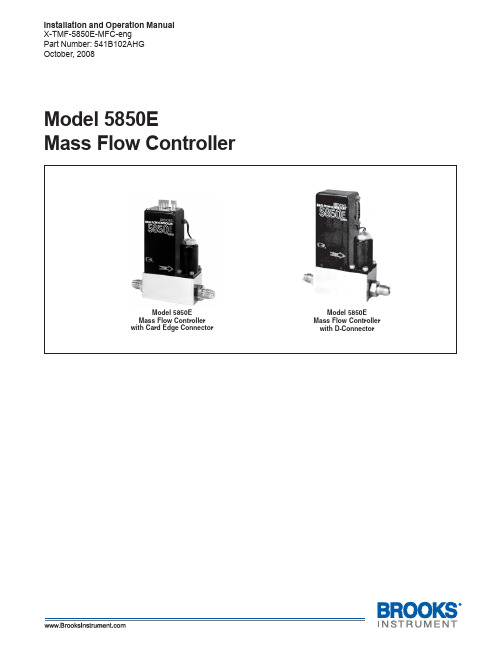
美国BROOKS5850E质量流量计
科里奥利质量流量计(变送器部分) Proline 500(数字)简明操作指南说明书
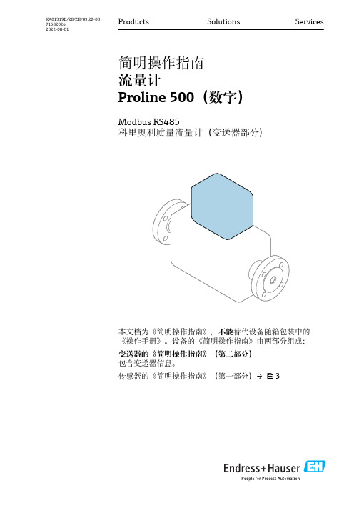
Products Solutions Services简明操作指南流量计Proline 500(数字)Modbus RS485科里奥利质量流量计(变送器部分)本文档为《简明操作指南》,不能替代设备随箱包装中的《操作手册》。
设备的《简明操作指南》由两部分组成:变送器的《简明操作指南》(第二部分)包含变送器信息。
传感器的《简明操作指南》(第一部分)→ 3KA01319D/28/ZH/03.22-00715820262022-08-01流量计 Proline 500(数字)2Endress+Hauser流量计 Proline 500(数字)流量计的《简明操作指南》Endress+Hauser 3流量计的《简明操作指南》仪表由一台变送器和一个传感器组成。
流量计的《简明操作指南》包含《传感器简明操作指南》和《变送器简明操作指南》,分别介绍了变送器和传感器调试操作:•第一部分:《传感器简明操作指南》•第二部分:《变送器简明操作指南》需要同时参照上述两本《简明操作指南》进行流量计调试,它们配套使用,互为补充:《传感器简明操作指南》(第一部分)《传感器简明操作指南》的文档对象是负责测量仪表安装的专业人员。
•到货验收和产品标识•储存和运输•安装《变送器简明操作指南》(第二部分)"《变送器简明操作指南》的文档对象是负责进行测量仪表调试、组态设置和参数设置的专业人员(直至获取第一个测量值)。
"•产品描述•安装•电气连接•操作方式•系统集成•调试•诊断信息其他设备文档本文档为《变送器简明操作指南》(第二部分)。
《传感器简明操作指南》(第一部分)的获取方式:•网址:/deviceviewer•智能手机/平板电脑:Endress+Hauser Operations App 详细设备信息参见《操作手册》和其他文档资料:•网址:/deviceviewer•智能手机/平板电脑:Endress+Hauser Operations App目录流量计 Proline 500(数字)4Endress+Hauser目录1文档信息 (5)1.1信息图标 (5)2安全指南 (7)2.1人员要求............................................................................72.2指定用途............................................................................72.3工作场所安全.........................................................................82.4操作安全............................................................................82.5产品安全............................................................................82.6IT 安全.............................................................................92.7设备的IT 安全........................................................................93产品描述 (10)4安装 (11)4.1立柱安装...........................................................................114.2墙装.............................................................................124.3变送器的安装后检查 (12)5电气连接 (13)5.1电气安全...........................................................................135.2接线要求...........................................................................135.3连接测量设备........................................................................185.4确保电势平衡........................................................................255.5硬件设置...........................................................................255.6确保防护等级........................................................................255.7连接后检查.........................................................................266操作方式 (27)6.1操作方式概述........................................................................276.2操作菜单的结构和功能.................................................................286.3通过现场显示单元访问操作菜单..........................................................296.4通过调试软件访问操作菜单.............................................................326.5通过Web 服务器访问操作菜单..........................................................327系统集成 (32)8调试 (33)8.1功能检查...........................................................................338.2设置显示语言........................................................................338.3设置测量设备........................................................................338.4写保护设置,防止未经授权的访问........................................................349诊断信息 (34)流量计 Proline 500(数字)文档信息1 文档信息1.1 信息图标1.1.1 安全图标危险状况警示图标。
brooks质量流量计5851e-mfc-说明书eng
We recommend that you read this manual in its entirety. Should you require any additional information concerning Brooks products and services, please contact your local Brooks Sales and Service Office listed on the back cover of this manual or visit
• Ensure that all equipment doors are closed and protective covers are in place, except when maintenance is being performed by qualified persons, to prevent electrical shock and personal injury.
LEFT BLANK
Installation and Operation Manual
X-TMF-5851E-MFC-eng Part Number: 541B104AAG November, 2008
Brooks® Model 5851E
Section 1 Introduction
MFC 质量流量计 图纸和资料
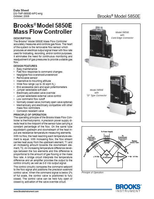
Brooks ® Model 5850EData SheetDS-TMF-5850E-MFC-eng October, 2008DESCRIPTIONThe Brooks ® Model 5850E Mass Flow Controlleraccurately measures and controls gas flows. The heart of the system is the removable flow sensor which produces an electrical output signal linear with flow rate used for indicating, recording, and/or control purposes.It eliminates the need for continuous monitoring and readjustment of gas pressures to provide a stable gas flow.DESIGN FEATURES •Easy maintenance•Fast flow response to command changes •Negligible flow overshoot/undershoot •Removable sensor•Insensitive to mounting attitude •Wide flow range (up to 30 slpm N 2)•End accessible zero and span potentiometers •Jumper selectable soft start•Electrically activated valve override•Jumper selectable external valve control •Low command flow cutoff•Normally closed valve (normally open valve optional)•Mechanically and electrically compatible with other mass flow controllers •Corrosion resistant valve PRINCIPLE OF OPERATIONThe operating principle of the Brooks Mass Flow Con-troller is thermodynamic. A precision power supply di-rects heat to the midpoint of the sensor tube carrying a constant percentage of the flow. On the same tube equidistant upstream and downstream of the heat in-put are resistance temperature measuring elements.With no flow, the heat reaching each temperature ele-ment is equal. With increasing flow, the flow stream carries heat away from the upstream element, T1 and an increasing amount towards the downstream ele-ment, T2. An increasing temperature difference devel-ops between the two elements and this difference is proportional to the amount of gas flowing or the mass flow rate. A bridge circuit interprets the temperature difference and an amplifier provides the output to the control circuitry as well as 0-5 Vdc output signal.The control circuitry compares the command setpoint to the flow signal and positions the precision solenoid control valve. When the command signal is below 2%of full scale, the control valve is positioned to fully closed. The control valve can be held fully open or closed by activation of the valve override circuit.Principle of OperationModel 5850EwithCard Edge ConnectorModel 5850Ewith"D" Type ConnectorBrooks ® Model 5850E Mass Flow ControllerBrooks ®Model 5850EData SheetDS-TMF-5850E-MFC-engOctober, 2008SPECIFICATIONSFlow RangesAny range from zero to 3 sccm* to zero to 30,000 sccm nitrogen equivalent.*Standard pressure and temperature in accordance with SEMI (Semiconductor Equipment and Materials In-stitute) proposed standard: 0°C and 101 kPa (760 T orr).Note: For full scale flow ranges greater than 50sccm Nitrogen equivalent.Performance: Accuracy: ±1% full scale including linearity at calibrated conditions. ±1.5% full scale for flow rates greater than 20 slpm.Repeatability: 0.25% of rate Control Range: 50 to 1Sensitivity to Mounting Attitude: ±0.5% F .S. maximum deviation from specified accuracy after rezeroing.Temperature SensitivityZero: Less than ±0.075% F .S. per degree CSpan: Less than ±1.0% F .S. shift from original calibration over 10-50°C range (50-122°F)Pressure Sensitivity: ±0.03% per psi up to 200 psig (N 2)Command Input Voltage0 to 5 Vdc (200 K ohms input resistance)Output Signals0 to 5 Vdc into 2000 ohms (or greater) load5 Vdc ±0.01 Vdc reference output, max. load 2 K ohm.Max. Operating Pressure1500 psig; 5-50 psid pressure drop (minimum pressure drop depends on gas and range)Temperature, Ambient/Gas: 41 to 149°F (5 to 65°C)Leak Integrity, Outboard1 x 10-10 atmosphere cc/sec. Helium Power RequirementsN.C. Valve (or N.O. Valve with flow £2.5 slpm)3.5 watts, +15 Vdc @ 35 mA, -15Vdc @ 180 mA N.O. Valve with flow rate > 2.5 slpm:10.5 watts, +15 Vdc @ 350 mA, -15 Vdc @ 350 mA Materials of ConstructionWetted Parts - Standard: Stainless Steel with Viton ®fluoroelastomer; Optional: Kalrez ® or Buna-N ConnectionsStandard: 9/16-18 UNF with Stainless Steel Compression Fittings; Optional: VCO TM and VCR TMElectrical Connections: Card Edge connector (gold plated) or D-type connector (DA-15P)DimensionsTRADEMARKSBrooks.....................................................Brooks Instrument, LLC Kalrez...........................................E.I. DuPont de Nemours & Co.VCO, VCR ......................................................................Cajon Co.Viton..........................................DuPont Performance ElastomersSpecifications Subject to Change Without NoticeModel 5850E Performance Curve (1 slpm N 2@ 25 psig)。
负载Pd基碳二选择加氢催化剂上乙炔加氢反应的原位红外光谱研究
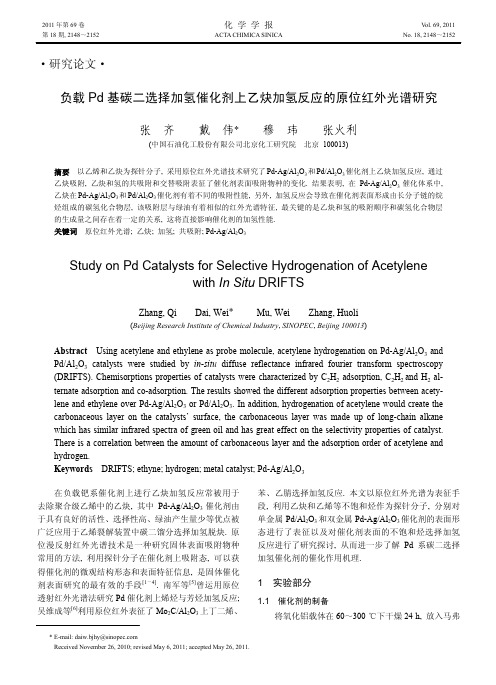
Bruker V70 傅立叶红外光谱仪(德国布鲁克公司), MCT 检测器; Harrick 漫反射附件包括不锈钢材质的高 温-真空原位红外池, 宇电 AI-708 智能程序升温控制柜, ZnSe 窗片; 配气装置(自制), 其中气体流量由 Brooks5850E 质 量 流 量 计 控 制 ( 美 国 艾 默 生 电 气 公 司 ); Agilent7890 气相色谱仪(美国安捷伦公司); Porapak N 不 锈钢填充色谱柱(Dikma 公司).
1.3 IR 测量方法
将 50 mg 左右催化剂样品粉末装入高温真空反应池 的样品杯中, 适当刮平, 红外光谱的分辨率设为 4 cm-1, 扫描 32 次, 通入高纯 H2, 流量调整至 10 mL/min, 以 20 ℃/min 的速度程序升温至 400 ℃, 还原催化剂 2 h 以上, 吹扫干净后摄取所需温度的背景光谱. 以高纯 Ar 为载 气将吸附气体引入载体或者催化剂样品表面进行动态 吸附, 每隔 2 min 采集数据一次, 吸附饱和后再切入高 纯 Ar 进行吹扫, 根据需要进行升温脱附并采集实时谱 图, 光谱以 Kubelka-Munk 方程给出, 反应尾气由原位 池引出经六通切换阀导入气相色谱仪进行分析, 测试条 件: 柱温 50 ℃、柱前压 18.2 psi、柱流量 22 mL/min、 分流比 50∶1、分析柱为 Porapak N (1.5 m, 80/100 目, 1/8).
2.2 Pd-Ag/Al2O3 催化剂上乙炔原位加氢反应的红外 光谱
2.2.1 乙炔和氢气共吸附
70 ℃下在 Pd-Ag/Al2O3 催化剂样品表面同时通入 1%C 2H2 和 1%H2 的混合标准气体进行吸附, 图 3 是乙炔 和氢在 Pd-Ag/Al2O3 催化剂上随时间变化的红外光谱, 我们发现随着吸附时间的增长, 乙炔的特征谱峰 3263 和 3309 cm-1 逐渐趋于饱和, 而在 35 min 时出现了 2966, 2929, 2893, 2878, 1465, 1460, 1372 cm-1等几个吸收峰归 属于饱和碳氢基团的伸缩振动和弯曲振动, 吸附 80 min 后上述 7 个吸收峰均达最强吸收, 表明吸附已达到饱和, 用高纯 Ar 气吹扫催化剂表面, 发现气相 C2H2 的吸收峰 消失, 升温至 150 ℃进行脱附后发现 2966~2878 cm-1 处的吸收峰明显减弱, 其中 2966, 2929, 2893, 2878 cm-1 附近的吸收峰分别归属于 CH3 的反对称伸缩振动、CH2 的反对称伸缩振动、CH3 的对称伸缩振动、CH2 的对称 伸缩振动; 1465 cm-1 是 CH2 的弯曲振动, 1460 cm-1 是 CH3 的不对称弯曲振动, 1372 cm-1 归属于 CH3 的对称弯 曲振动[8,11~14].
Bronkhorst CORI-FLOW 质量流量计 控制器 M54 M55 手册说明书
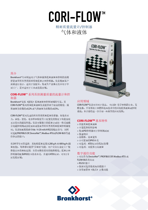
简介Bronkhorst®专业制造用于气体和液体流量测量和控制的高精密紧凑型科里奥利原理质量流量计和控制器。
仪表根据客户需求进行设计,适用于实验室、集成生产设备以及应用于中试工厂,甚至适用于工业或危险区域。
CORI-FLOW™系列直接测量质量的流量计和控制器Bronkhorst®是低(超低)流量测量和控制领域的专家。
其CORI-FLOW™系列质量流量测量仪表提供两个级别的精度:液体测量为读数的±0,2% 或气体测量为读数的±0,5%。
CORI-FLOW™采用先进的科里奥利质量流量传感器,即使在压力、温度、密度、电导率和粘度等工况变化的情况下也能实现无以伦比的超高性能。
仪表可做独立的流量计或同一体式强耦合电磁控制阀或齿轮泵组成紧凑型科里奥利质量流量控制器使用。
仪表标配模拟(0-5 Vdc / 4-20 mA)和RS232输出信号,同时可选配PROFIBUS DP, DeviceNet™, Modbus-RTU或FLOW-BUS等通信协议的接口。
有2种型号可供选择,其标称流量范围从200 g/h 到 600 kg/h (满量程值),每种都可提供“多量程”功能:用户可自行设定工厂校准值以外的量程范围,且仍可维持原有的校准精度。
流量计和控制器均配备IP65防尘防水外壳,并通过ATEX认证,可用于2区危险区域。
应用领域CORI-FLOW™仪表可应用于食品、(石油)化学和制药行业、发酵设备、半导体加工和燃料电池技术中的过程流体测量或控制系统。
本手册将进一步介绍一些典型的应用案例。
CORI-FLOW TM基本特性> 直接质量流量测量> 不受流体特性影响> 集成PID控制器用于控制阀或泵> 快速响应> 高精准,高重复性> 小巧紧凑的IP65外壳> 可选项:ATEX认证3类2区防爆> 可选项:双流体方向测量数字通信功能> 可以作为 DeviceNet™, PROFIBUS DP, Modbus-RTU 或FLOW-BUS 的从站> RS232 接口> 按需可选其他现场总线接口> 异常报警和(批次)计数功能CORI-FLOW TM 精密质量流量计/控制器气体和液体测量原理CORI-FLOW TM 包含两个平行的U 型管,形成振荡系统的一部分。
MFC 质量流量计 图纸和资料

Brooks ® Model 5850EData SheetDS-TMF-5850E-MFC-eng October, 2008DESCRIPTIONThe Brooks ® Model 5850E Mass Flow Controlleraccurately measures and controls gas flows. The heart of the system is the removable flow sensor which produces an electrical output signal linear with flow rate used for indicating, recording, and/or control purposes.It eliminates the need for continuous monitoring and readjustment of gas pressures to provide a stable gas flow.DESIGN FEATURES •Easy maintenance•Fast flow response to command changes •Negligible flow overshoot/undershoot •Removable sensor•Insensitive to mounting attitude •Wide flow range (up to 30 slpm N 2)•End accessible zero and span potentiometers •Jumper selectable soft start•Electrically activated valve override•Jumper selectable external valve control •Low command flow cutoff•Normally closed valve (normally open valve optional)•Mechanically and electrically compatible with other mass flow controllers •Corrosion resistant valve PRINCIPLE OF OPERATIONThe operating principle of the Brooks Mass Flow Con-troller is thermodynamic. A precision power supply di-rects heat to the midpoint of the sensor tube carrying a constant percentage of the flow. On the same tube equidistant upstream and downstream of the heat in-put are resistance temperature measuring elements.With no flow, the heat reaching each temperature ele-ment is equal. With increasing flow, the flow stream carries heat away from the upstream element, T1 and an increasing amount towards the downstream ele-ment, T2. An increasing temperature difference devel-ops between the two elements and this difference is proportional to the amount of gas flowing or the mass flow rate. A bridge circuit interprets the temperature difference and an amplifier provides the output to the control circuitry as well as 0-5 Vdc output signal.The control circuitry compares the command setpoint to the flow signal and positions the precision solenoid control valve. When the command signal is below 2%of full scale, the control valve is positioned to fully closed. The control valve can be held fully open or closed by activation of the valve override circuit.Principle of OperationModel 5850EwithCard Edge ConnectorModel 5850Ewith"D" Type ConnectorBrooks ® Model 5850E Mass Flow ControllerBrooks ®Model 5850EData SheetDS-TMF-5850E-MFC-engOctober, 2008SPECIFICATIONSFlow RangesAny range from zero to 3 sccm* to zero to 30,000 sccm nitrogen equivalent.*Standard pressure and temperature in accordance with SEMI (Semiconductor Equipment and Materials In-stitute) proposed standard: 0°C and 101 kPa (760 T orr).Note: For full scale flow ranges greater than 50sccm Nitrogen equivalent.Performance: Accuracy: ±1% full scale including linearity at calibrated conditions. ±1.5% full scale for flow rates greater than 20 slpm.Repeatability: 0.25% of rate Control Range: 50 to 1Sensitivity to Mounting Attitude: ±0.5% F .S. maximum deviation from specified accuracy after rezeroing.Temperature SensitivityZero: Less than ±0.075% F .S. per degree CSpan: Less than ±1.0% F .S. shift from original calibration over 10-50°C range (50-122°F)Pressure Sensitivity: ±0.03% per psi up to 200 psig (N 2)Command Input Voltage0 to 5 Vdc (200 K ohms input resistance)Output Signals0 to 5 Vdc into 2000 ohms (or greater) load5 Vdc ±0.01 Vdc reference output, max. load 2 K ohm.Max. Operating Pressure1500 psig; 5-50 psid pressure drop (minimum pressure drop depends on gas and range)Temperature, Ambient/Gas: 41 to 149°F (5 to 65°C)Leak Integrity, Outboard1 x 10-10 atmosphere cc/sec. Helium Power RequirementsN.C. Valve (or N.O. Valve with flow £2.5 slpm)3.5 watts, +15 Vdc @ 35 mA, -15Vdc @ 180 mA N.O. Valve with flow rate > 2.5 slpm:10.5 watts, +15 Vdc @ 350 mA, -15 Vdc @ 350 mA Materials of ConstructionWetted Parts - Standard: Stainless Steel with Viton ®fluoroelastomer; Optional: Kalrez ® or Buna-N ConnectionsStandard: 9/16-18 UNF with Stainless Steel Compression Fittings; Optional: VCO TM and VCR TMElectrical Connections: Card Edge connector (gold plated) or D-type connector (DA-15P)DimensionsTRADEMARKSBrooks.....................................................Brooks Instrument, LLC Kalrez...........................................E.I. DuPont de Nemours & Co.VCO, VCR ......................................................................Cajon Co.Viton..........................................DuPont Performance ElastomersSpecifications Subject to Change Without NoticeModel 5850E Performance Curve (1 slpm N 2@ 25 psig)。
美国TSI质量流量计5000系列
我们是一家专注于医疗器械测试产品和技术的研发、销售与服务为一体的“国家高新技术企业”,我们拥有自主研发的国家发明专利技术并且代理了众多国内外先进专业测试产品。
本文将带大家了解美国TSI质量流量计5000系列的两款产品。
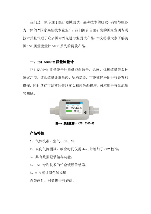
一、TSI 5300-2质量流量计TSI 5300-2质量流量计提供双向流量、温度、体积流量等多种测试功能。
该款流量计重量轻,结构紧凑,可快速轻松地进行设置和操作,同时具有可调整的管路接头和彩色触摸屏。
可应用于气体流量等测试。
图一:质量流量计(TSI 5300-2)产品特性1、气体校准:空气、O2、N2;2、双向气流测试,响应时间仅需4ms,并增加了CO2校准;3、具有数据记录储存功能;4、TSI 专利技术的铂金镀膜传感器;5、2.8英寸彩色触摸屏;自带软件,对数据进行查阅。
技术参数1、流量测试范围:0至±300 Std L/min(Air, O2, N2);0至±100 Std L/min (CO2) ;精度:2%的读数或者0.05L/min;响应时间:4ms至63% of full scale;2、体积测试:0.004至99L,2%的读数或者1mL;3、温度测试:-10至50°C,准确度:±1° C;4、绝对压力测试:50至200 kPa,±1 kPa;5、供电:USB;显示:2.8英寸触摸屏。
二、TSI 5330-2质量流量计TSI 5330-2质量流量计提供双向流量测量,集合了压差、温度、湿度和体积流量等多种测试功能。
该款流量计重量轻,结构紧凑,可快速轻松地进行设置和操作,同时具有可调整的管路接头和彩色触摸屏。
可应用于呼吸气流通气设备、气腹机等测试。
图二:质量流量计(TSI 5330-2)产品特性1、气体校准:空气、O2、N2;2、双向气流测试,响应时间仅需4ms,并增加了CO2校准;3、可同时显示四个测量参数;4、具有数据记录储存功能;5、TSI 专利技术的铂金镀膜传感器;6、2.8英寸彩色触摸屏;自带软件,对数据进行查阅。
电磁流量计说明书(布鲁克斯)
intelligent magnetic flowmeter
使 用 说 明 书
版本:2013
在使用仪表前,请仔细阅读本说明书!
1、产品特点……………………………………………………………………… 1
2、主要技术参数…………………………………………………………………2
3、电磁流量计选型说明………………………………………………………… 3
E=KBdv
式中:E---------------为电极间的信号电压(v)
B-----------------磁通密度(T)
d------------------测量管内径(m)
v------------------平均流速(m/s)
式中k, d为常数,由于励磁电流是恒流的,故B也是常数,则由E=KBdv可知,体积流量Q与信号电压E-成正比,即流速感应的信号电压E与体积Q成线性关系。因此,只要测量出E就可确定流量Q,这是电磁流量计的基本工作原理。
腐蚀性的酸碱盐液体
聚乙烯
PO
化学性能稳定
<60℃
污水
聚苯硫醚
PPS
<150℃
热水
五、流量范围的选择
最大流量和最小流量必须符合下表中的数。
Qmin(m3/h)
Qmax(m3/h)
0.0283
4.24
0.0636
9.54
0.12
16.96
0.176
26.5
0.29
43.42
0.452
67.85
0.7
106.0
●输出电流及负载电阻:
4~20mA全隔离负载电阻<750欧姆脉冲频率0-1KHZ光电隔离OCT外接电源≤35V
导通时 集电极最大电流为25mA
8850-1-xrh GF电导仪说明书
1.0000
> 入精确的电导常数
Cond Units:
uS
>
PPM Factor:
2.00
>
Set: Temperature >
Set: Conductivity >
Loop Source:
Cond
>
选择测量值单位:uS, mS, kΩ, MΩ, PPM
如果测量值单位设定为 PPM,要在此项中设置固体溶解总量(Total Dissolved Solids)与 uS 的比例。详见本说明书的章节 3。TDS 系数只 能按 PPM 单位设置。
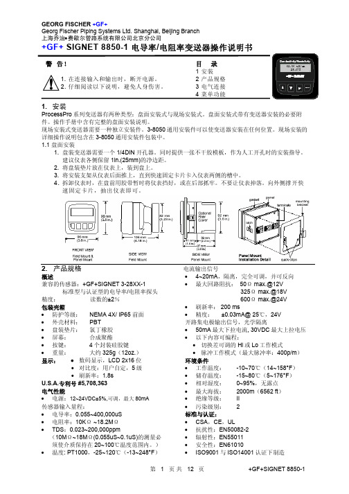
3.3 开路集电极输出信号 当过程变量高于或低于设定值时,开路集电极 输出信号可以用作开关量信号,或根据过程变 量发出比例脉冲信号。
• Low 当过程变量低于设定值时,输出信号被激励。 当流量值高于设定值加切换差时,输出信号复 位。
• 比例脉冲 开路集电极将根据标定菜单(CALIBRATE)中 设定的脉冲率发出 100ms 宽的脉冲信号。
目录
1 安装 2 产品规格 3 电气连接 4 菜单功能
1. 安装
ProcessPro 系列变送器有两种类型:盘面安装式与现场安装式。盘面安装式带有变送器安装的必要附 件。操作手册中含有完整的盘面安装说明。
现场安装式变送器需要一种独立安装件。3-8050 通用安装件可以使变送器安装在任何位置。现场安装的 详细操作说明包含在 3-8050 通用安装件包装中。 1.1 盘面安装
在下面的示例中: • 当测量值小于 5.0 时,输出信号为 0p/m。 • 当测量值等于 7.5 时,输出信号为 50p/m。 • 当测量值达到 10 及以上时,输出信号为
100p/m
艾默生质量流量计1700hart菜单

temp damping温度阻尼
update rate刷新速度
update rate刷新速度
100HZ variables100HZ显
示变量
set up special unit设置特殊单位
mass special unit质量特殊 单位
volume special unit体积特 殊单位
max pulse width最大脉冲宽度
FO polarity脉 冲极性
FO fault parameter故障参数
third variable第二变量
FO fault action故障动 作
FO fault level故障等级
FO scaling定标
FO scaling method定标方 式
set FO scaling设置定标系数
sensor mode传感器型
drive gain驱动增益
input voltage输入电 压
LPO amplitude左线圈 幅值
RPO amplitude右线圈 幅值
board temperature电 路板温度
tube frequency传感 器振动频率
live zero活零点
Fld verification zero现场确认零点
trends趋势
meter verification仪表自校验
configure组 态
manual setup手动设 置
characterize特性化
sensor type传感器类 型
curved tube弯管
sensor tag parameters传感
器铭牌参数
flowcal流 量系数
BROOKS流量计5850E使用手册
THIS PAGE WAS INTENTIONALLY
LEFT BLANK
Installation and Operation Manual
Contents
X-TMF-5850E-MFC-eng
Comments This instrument is not unique in its content of ESD (electrostatic discharge) sensitive components. Most modern electronic designs contain components that utilize metal oxide technology (NMOS, CMOS, etc.). Experience has proven that even small amounts of static electricity can damage or destroy these devices. Damaged components, even though they appear to function properly, exhibit early failure.
• Inform and educate your personnel in the proper installation, operation and maintenance of the product.
• Install your equipment as specified in the installation instructions of the appropriate instruction manual and per applicable local and national codes. Connect all products to the proper electrical and pressure sources.
DMF-1 系列 U 型质量流量计说明书

DMF-1系列U型质量流量计说明书目录第一章概述 (3)1.1工作原理: (4)1.2仪表参数和选型说明 (6)1.3流量计结构 (9)14精度曲线图 (13)第二章质量流量计的安装与调试 (15)2.1传感器的安装 (15)2.2接线说明 (18)2.3仪表的通电和检查 (20)2.4常见故障的排除 (20)2.5维修与保养 (21)第三章变送器的设置 (21)3.1功能设置 (21)3.2仪表面板操作 (22)3.3零点校准 (28)第四章防爆 (29)第五章MODBUS(RTU)相关说明 (30)第六章选型指南 (33)第一章 概述DMF-1系列质量流量计是根据科里奥利(Coriolis Force)原理,实现流体质量流量的直接精密测量,而无需任何压力、温度、粘度、密度等换算或修正。
其结构是由传感器单元和变送器单元两部分组成。
仪表按本质安全防爆型的国家标准设计与制造,防爆标志为EX d ib II C T5 Gb科里奥利质量流量计能够直接测量流体的质量,具有高精度(0.1%~0.2%),应用范围广(可测量各种非牛顿流体、各种浆液、悬浮液、高粘度流体等),安装要求低(对仪表的前后直管段要求不高),运行可靠、稳定,维修率低等特点。
我公司对说明书的全部内容拥有最终的解释权,并有权对说明书的内容进行修改。
警告危险场合的不正确安装和操作可能产生危险关于危险场合的技术参数,请参考防爆部分说明341.1工作原理 :当一个位于以P 点为旋转中心做旋转运动的管子内的质点做朝向或远离旋转中心的运动时,将产生一贯性力,原理如图1:图1图中质量为δm的质点以匀速v 围绕一个固定点P 并以角速度ω旋转的管道内移动时,这个质点将获得两个加速度分量:1. 法向加速度αr (向心加速度),其量值值等于ω2r,方向朝向P 点; 2. 切向加速度αt (科里奥利加速度),其量值等于2ωv,方向与αr 垂直。
根据牛顿第二运动定律(力=质量X 加速度),产生科里奥利加速度αt ,必定在αt 的方向上施加一个相应的力,其大小等于2ωvδm,这个力来自向上转动的管道。
EPI质量流量计
9000 系列质量流量计直接测量气体的质量流率,对介质温度变化进行补偿, 对压力变化不敏感,所以不需要补偿可直接输入数据采集系统。
4
电话: 86-411-8466 2327 网址:
EPI 产品中国代理 2.6 安装连接方式 2.6.1 锥管螺纹连接 锥管螺纹尺寸由 1/4″-4″ 2.6.2 法兰连接 2.6.3 管附件连接 2.6.4 球阀连接
三. 产品技术参数
大连海璐科技有限公司
测量介质: 组份较稳定的单一或混合气体;
除多点流量计外,9000 系列均速探头(Flow Average Tube)流量计是 EPI 公司最新独创的技术,特别适合大口径管道的测量(可提高精度和减少对前后安 装直管段长度的要求,一般安装前后只需 1D),价格与单点流量计相当,但较 单点流量计有更好的准确度和稳定性。
二.产品分类 、外型尺寸和接口方式
插入式流量计要求将探头插入杆插入用户管道中,并与之垂直。安装管附件 时首先在流通管壁上钻一可以插入探头的孔,焊上或旋出螺纹,然后将管附件焊 上,或者拧入已焊接在流通管上的尺寸合适的匹配管接头上。压力较高时,应加 一固定装置如球阀,以防止拆除变送器时,它会高速弹出。
2.3 根据测量管上探头数量的多少,可分为单点式和多点式流量计。
美国 EPI 公司热式气体质量流量计
THERMAL GAS MASS FLOW METER
EPI 中国代理
Hainova 大 连 海 璐 科 技 有 限 公 司
西格纳特 8550-2 流量传感器用户手册说明书
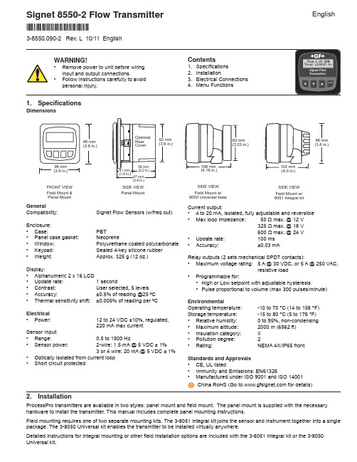
Signet 8550-2 Flow TransmitterCurrent output:• 4 to 20 mA, isolated, fully adjustable and reversible• Max loop impedance: 50 Ω max. @ 12 V325Ω max. @ 18 V600Ω max. @ 24 V• Update rate: 100 ms• Accuracy: ±0.03 mARelay outputs (2 sets mechanical SPDT contacts):• Maximum voltage rating: 5 A @ 30 VDC, or 5 A @ 250 VAC,resistive load• Programmable for:• High or Low setpoint with adjustable hysteresis• Pulse proportional to volume (max 300 pulses/minute)EnvironmentalOperating temperature: -10 to 70 °C (14 to 158 °F)Storage temperature: -15 to 80 °C (5 to 176 °F)• Relative humidity: 0 to 95%, non-condensing• Maximum altitude: 2000 m (6562 ft)• Insulation category: II• Pollution degree: 2• Rating: NEMA 4X/IP65 frontStandards and Approvals• CE, UL listed• Immunity and Emissions: EN61326• Manufactured under ISO 9001 and ISO 14001China RoHS (Go to for details)GeneralCompatibility: Signet Flow Sensors (w/freq out)Enclosure:• Case: PBT• Panel case gasket: Neoprene• Window: Polyurethane coated polycarbonate• Keypad: Sealed 4-key silicone rubber• Weight: Approx. 325 g (12 oz.)Display:• Alphanumeric 2 x 16 LCD• Update rate: 1 second• Contrast: User selected, 5 levels• Accuracy: ±0.5% of reading @25 ºC• Thermal sensitivity shift: ±0.005% of reading per ºCElectrical• Power: 12 to 24 VDC ±10%, regulated,220 mA max currentSensor Input:• Range: 0.5 to 1500 Hz• Sensor power: 2-wire: 1.5 mA @ 5 VDC ± 1%3 or4 wire: 20 mA @5 VDC ± 1%• Optically isolated from current loop• Short circuit protected2. InstallationProcessPro transmitters are available in two styles: panel mount and fi eld mount. The panel mount is supplied with the necessary hardware to install the transmitter. This manual includes complete panel mounting instructions.Field mounting requires one of two separate mounting kits. The 3-8051 integral kit joins the sensor and instrument together into a single package. The 3-8050 Universal kit enables the transmitter to be installed virtually anywhere.Detailed instructions for integral mounting or other fi eld installation options are included with the 3-8051 Integral kit or the 3-8050 Universal kit.(3.8 in.)SIDE VIEWField Mount w/8051 Integral kitSIDE VIEWField Mount w/8050 Universal basePanel MountSIDE VIEWFRONT VIEWField Mount &Panel Mount1. Specifi cations3-8550.090-2 Rev. L 10/11 English*3-8550.090-2*English Dimensions43 2 11312111098765System PwrLoop -System PwrLoop +AUXPower -AUXPower +Sensr Gnd(SHIELD)Sensr IN(RED)Sensr V+(BLACK)Relay 2(NO)Relay 2(COM)Relay 2(NC)Relay 1(NO)Relay 1(COM)Relay 1(NC)ConnectionsCAUTION: Failure to fully open terminal jaws before removing wire may permanently damage instrument.Wiring Procedure1. Remove 0.5 - 0.625 in. (13-16 mm) of insulation from wire end.2. Press the orange terminal lever downward with a small screwdriver to open terminal jaws.3. Insert exposed (non-insulated) wire end in terminal hole until it bottoms out.4. Release orange terminal lever to secure wire in place. Gently pull on each wire to ensure a good connection.Wiring Removal Procedure1. Press the orange terminal lever downward with a small screwdriver to open terminal jaws.2. When fully open, remove wire from terminal.Terminals 5-10: Relay OutputsTwo sets mechanical SPDT contacts,programmable (see CALIBRATE menu) as:• H igh or Low setpoint with adjustablehysteresis• Volumetric pulse based on totalizer• May be disabled (Off) if not used.Terminals 3 and 4: Loop Power12-24 VDC ±10% system powerand current loop output.Max. loop impedance:50 Ω max. @ 12 V325 Ω max. @ 18 V600 Ω max. @ 24 VTerminals 11-13: Flow sensor input Installation1. The panel mount transmitter is designed for installation using a 1/4 DIN Punch. Formanual panel cutout, an adhesive template is provided as an installation guide.Recommended clearance on all sides between instruments is 1 inch.2. Place gasket on instrument, and install in panel.3. Slide mounting bracket over back of instrument until quick-clips snap into latches on sideof instrument.4. To remove, secure instrument temporarily with tape from front or grip from rear ofinstrument. DO NOT RELEASE.Press quick-clips outward and remove.Terminals 1 and 2: AUXILIARY powerUsed only if the fl ow sensor requires morethan 1.5 mA current. For Signet sensors thisis limited to the following products:• 2000 • 2507 • 2551 • 2552• Open-collector Input signals2Signet 8550-2 Flow Transmitter3Signet 8550-2 Flow Transmitter 3.1 System Power/Loop Connections3.2 Sensor Input ConnectionsWiring Tips:• Do not route sensor cable in conduit containing AC power wiring.Electrical noise may interfere with sensor signal.• Routing sensor cable in grounded metal conduit will help preventelectrical noise and mechanical damage.• Seal cable entry points to prevent moisture damage.• Only one wire should be inserted into a terminal. Splice double wiresoutside the terminal.131211No Aux Power 515/3-8510-XX 52521002536/3-8512-XX 2540Aux Power2000250725512552Open Coll. InputTerminalsSensr Gnd (SHIELD)Sensr IN (RED)Sensr V+(BLACK)AUXILIARY power is required for all systems where relays are used.Stand-alone application, no current loop usedTransmitter Maximum cable length is 200 ft for 515/8510-XX, 525 and any sinusoidal fl ow signal.Maximum cable length is 1000 ft for 2536/8512-XX, 2537, 2540 and any open collector fl ow signal.4Signet 8550-2 Flow TransmitterHysteresisLow SetpointRelay energized Relay de-energizedHigh SetpointVIEW menu• During normal operation, the ProcessPro displays the VIEW menu.• When using the CALIBRATE or OPTIONS menus, the ProcessPro will return to the VIEW menu if no activityoccurs for 10 minutes.• To select the item you want displayed, press the UP or DOWN arrow keys. The items will scroll in a continuousloop. Changing the display selection does not interrupt system operations.• No key code is necessary to change display selection.• Output settings cannot be edited from the VIEW menu.3.3 Relay OutputThe relay outputs can be programmed to respond when the fl ow rate moves above or below a setpoint, or they can be used to generate a pulse that is relative to the fl ow volume. The relays can be disabled if not in use.• LowRelay energizes when the fl ow rate is less than the setpoint.The relay de-energizes when the fl ow rate moves above the setpoint plus the hysteresis value.• HighRelay energizes when the fl ow rate is greater than the setpoint.The relay will de-energize when the fl ow rate drops below the setpoint plus the hysteresis value.• PulseRelay output is a pulse based on the volume of fl uid that passesthe sensor. Set any value from 0.0001 to 99999.View MenuDisplayDescription5Signet 8550-2 Flow Transmitter Notes on Steps 5 and 6:• All output functions remain active during editing.• Only the fl ashing element can be edited.• RIGHT ARROW key advances the fl ashing element in a continuous loop.• Edited value is effective immediately after pressing ENTER key.• If no key is pressed for 10 minutes unit will restore the last saved value and return to step 3.• Step 6 (pressing ENTER key) always returns you to Step 3.• Repeat steps 3-6 until all editing is completed.Notes on Steps 3 and 4:• Refer to pages 6 and 7 for complete listing of menu items and their use.• From the Step 3 display, pressing the UP and DOWN keys simultaneously will return the display to the VIEW menu.• If no key is pressed for 10 minutes, display will also return to the VIEW menu.ProcessPro Editing Procedure:Step 1. Press and hold ENTER key:• 2 seconds to select the CALIBRATE menu • 5 seconds to select the OPTIONS menu.Step 2. The Key Code is UP-UP-UP-DOWN keys in sequence.• After entering the Key Code, the display will show the fi rst item in the selected menu.Step 3. Scroll menu with UP or DOWN arrow keys.Step 4. Press RIGHT ARROW key to select menu item to be edited.• The fi rst display element will begin fl ashing.Step 5. Press UP or DOWN keys to edit the fl ashing element.• RIGHT ARROW key advances the fl ashing element.Step 6. Press ENTER key to save the new setting and return to Step 3.Step 46Signet 8550-2 Flow TransmitterAll Relay settings repeat for Relay 2.Calibrate MenuDisplay(Factory settings shown)Description7Signet 8550-2 Flow Transmitter Options Menu10 s 2 s 20 s 30 s 40 s 50 s 60 s70 sthe 8550 responds to every unstable shift in the fl ow. The dashed red line represents the actual output of the fl ow sensor in unstable fl ow conditions .zero the flow rate is stabilized, but a sharp change in fl ow rate is not represented for 50 seconds or longer. (dotted green line).the fl ow rate is stabilized, while the sudden shift in fl ow is re fl ected very quickly. (Solid blue line)NOTE: The SENSITIVITY function is ineffective if the AVERAGING function is set to zero (seconds).Display(Factory settings shown)DescriptionTroubleshootingGeorg Fischer Signet LLC, 3401 Aerojet Avenue, El Monte, CA 91731-2882 U.S.A. • Tel. (626) 571-2770 • Fax (626) 573-2057For Worldwide Sales and Service, visit our website: • Or call (in the U.S.): (800) 854-4090For the most up-to-date information, please refer to our website at 3-8550.090-2 Rev L 10/11 English© George Fischer Signet, Inc. 2011Ordering InformationMfr. Part No.CodeDescription3-8550-1 159 000 047 Flow transmitter, Field mount 3-8550-1P 159 000 048 Flow transmitter, Panel mount3-8550-2 159 000 049 Flow transmitter, Field mount with relays 3-8550-2P 159 000 050 Flow transmitter, Panel mount with relays3-8550-3 159 000 051 Flow transmitter, Field mount with dual input/output 3-8550-3P159 000 052Flow transmitter, Panel mount with dual input/outputAccessoriesMfr. Part No.CodeDescription3-8050 159 000 184 Universal mounting kit 3-8051 159 000 187 Flow Integral Mnt NPT 3-8050.395 159 000 186 Splashproof rear cover 3-8050.396 159 000 617 RC Filter kit (for relay use)3-0000.596 159 000 641 Heavy duty wall mount bracket 3-5000.598 198 840 225 Surface Mount Bracket3-5000.399 198 840 224 5 x 5 inch adapter plate for Signet retro fi t3-9000.392 159 000 368 Liquid tight connector kit for rear cover (includes 3 connectors)3-9000.392-1 159 000 839 Liquid tight connector kit, NPT (1 piece)3-9000.392-2 159 000 841 Liquid tight connector kit, PG13.5 (1 piece)7300-7524 159 000 687 24 VDC Power Supply 7.5 W, 300 mA 7300-1524 159 000 688 24 VDC Power Supply 15 W, 600 mA 7300-3024 159 000 689 24 VDC Power Supply 30 W, 1.3 A 7300-5024 159 000 690 24 VDC Power Supply 50 W, 2.1 A 7300-1024159 000 69124 VDC Power Supply 100 W, 4.2 ADisplay Condition Possible CausesSuggested Solutions。
BROOKs浮子流量计
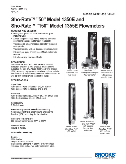
DESCRIPTION The Sho-Rate 1350 and 1355 Series of low flow indicators provides a cost-effective means of flow indication for both 5% (Model 1355) and 10% (Model 1350) accuracy requirements. Available options include the Standard or NRSTM integral needle control valves, as well as flow controllers on the inlet or outlet.
Model 1355E Sho-Rate "150"
(No valve)
Model 1355E-8800 Sho-Rate "150" with optional integral flow controller
Model 1355E Sho-Rate "150"
with optional needle valve
• Tubes sealed on compression gasket by threaded seal spindle
• Tubes removable without disconnecting instrument
• Integral float stops prevent loss of float during tube removal
Models 1350E and 1355E
(CCaarrtriddggeeIVOOpepenn)
科里奥利质量流量计 Proline Promass E 500 PROFIBUS PA 操作手册说明

Products Solutions Services操作手册Proline Promass E 500科里奥利质量流量计PROFIBUS PABA01550D/28/ZH/03.21715122232021-01-01自下列版本起生效01.01.zz (设备固件)Proline Promass E 500 PROFIBUS PA•请将文档妥善保存在安全地方,便于操作或使用设备时查看。
•为了避免出现人员或装置危险,请仔细阅读“基本安全指南”章节,以及针对特定操作步骤的文档中的所有其他安全指南。
•制造商保留修改技术参数的权利,将不预先通知。
Endress+Hauser当地销售中心将为您提供最新文档信息和更新文档资料。
2Endress+HauserProline Promass E 500 PROFIBUS PA 目录Endress+Hauser 3目录1文档信息 (6)1.1文档功能 (6)1.2信息图标 (6)1.2.1安全图标 (6)1.2.2电气图标 (6)1.2.3通信图标 (6)1.2.4工具图标 (7)1.2.5特定信息图标 (7)1.2.6图中的图标 (7)1.3文档资料 (8)1.3.1标准文档资料 (8)1.3.2补充文档资料 (8)1.4注册商标 (8)2安全指南 (9)2.1人员要求 (9)2.2指定用途 (9)2.3工作场所安全 (10)2.4操作安全 (10)2.5产品安全 (10)2.6IT 安全 (10)2.7设备的IT 安全 (11)2.7.1通过硬件写保护实现访问保护 (11)2.7.2密码访问保护 (11)2.7.3通过网页服务器访问 (12)2.7.4通过服务接口(CDI-RJ45)访问 (12)3产品描述 (13)3.1产品设计 (13)3.1.1Proline 500数字式 (13)3.1.2Proline 500变送器 (14)4到货验收和产品标识 (15)4.1到货验收 (15)4.2产品标识 (15)4.2.1变送器铭牌 (16)4.2.2传感器铭牌 (18)4.2.3测量设备上的图标 (19)5储存和运输 (20)5.1储存条件 (20)5.2运输产品 (20)5.2.1不带起吊吊环的测量仪表 (20)5.2.2带起吊吊环的测量设备 (21)5.2.3使用叉车搬运 (21)5.3包装处置 (21)6安装 (21)6.1安装条件 (21)6.1.1安装位置 (21)6.1.2环境条件和过程条件要求 (24)6.1.3特殊安装指南 (25)6.2安装测量设备........................276.2.1所需工具.....................276.2.2准备测量设备..................276.2.3安装测量设备..................286.2.4安装Proline 500(数字)变送器外壳........................286.2.5安装变送器外壳:Proline 500(模拟).........................306.2.6旋转变送器外壳:Proline 500(模拟).........................316.2.7旋转显示模块:Proline 500.......316.3安装后检查..........................327电气连接..........................337.1接线...............................337.1.1所需工具.....................337.1.2连接电缆要求..................337.1.3接线端子分配..................377.1.4可选仪表插头..................377.1.5设备插头的针脚分配.............377.1.6屏蔽和接地....................387.1.7准备测量设备..................397.2连接测量设备:Proline 500(数字)变送器................................407.2.1连接连接电缆..................407.2.2连接信号电缆和供电电缆.........457.3连接测量设备:Proline 500(模拟)变送器................................477.3.1连接连接电缆..................477.3.2连接信号电缆和供电电缆.........507.4确保电势平衡........................527.4.1要求.........................527.5特殊接线指南........................537.5.1连接实例.....................537.6硬件设置............................567.6.1设置设备地址..................567.6.2使用缺省IP 地址...............577.7确保防护等级........................597.8连接后检查..........................598操作方式..........................608.1操作方式概述........................608.2操作菜单的结构和功能.................618.2.1操作菜单结构..................618.2.2菜单结构.....................628.3通过现场显示单元访问操作菜单..........638.3.1操作界面.....................638.3.2菜单视图.....................648.3.3编辑界面.....................668.3.4操作部件.....................688.3.5打开文本菜单..................688.3.6在列表中查看和选择.............708.3.7直接查看参数..................708.3.8查询帮助文本 (71)目录Proline Promass E 500 PROFIBUS PA 4Endress+Hauser8.3.9更改参数 (71)8.3.10用户角色及其访问权限 (72)8.3.11通过访问密码关闭写保护 (72)8.3.12打开和关闭键盘锁 (72)8.4通过网页浏览器访问操作菜单 (73)8.4.1功能列表 (73)8.4.2前提 (73)8.4.3建立连接 (74)8.4.4登录 (76)8.4.5用户界面 (77)8.4.6关闭网页服务器 (78)8.4.7退出 (78)8.5通过调试软件访问操作菜单 (78)8.5.1连接调试软件 (79)8.5.2FieldCare (82)8.5.3DeviceCare (83)8.5.4SIMATIC PDM (84)9系统集成 (85)9.1设备描述文件概述 (85)9.1.1当前设备版本信息 (85)9.1.2调试软件 (85)9.2设备数据库文件(GSD) (85)9.2.1制造商GSD 文件 (85)9.2.2Profile GSD 文件 (86)9.3与老版本兼容 (87)9.3.1自动识别(工厂设置) (87)9.3.2手动设置 (87)9.3.3更换测量设备,无需更改GSD 文件或重启控制器 (87)9.4使用老产品型号的GSD 文件 (88)9.4.1使用老产品型号的CONTROL_BLOCK 块 (88)9.5循环数据传输 (90)9.5.1块 (90)9.5.2块说明 (90)10调试 (98)10.1功能检查 (98)10.2开启测量设备 (98)10.3通过FieldCare 连接 (98)10.4软件地址设定 (98)10.4.1PROFIBUS 网络 (98)10.5设置操作语言 (98)10.6设置测量设备 (99)10.6.1设置位号名 (100)10.6.2设置系统单位 (101)10.6.3选择和设置介质 (104)10.6.4设置通信接口 (105)10.6.5设置模拟量输入 (106)10.6.6显示输入/输出设置 (107)10.6.7设置电流输入 (108)10.6.8设置状态输入 (109)10.6.9设置电流输出 (110)10.6.10设置脉冲/频率/开关量输出 (113)10.6.11设置继电器输出 (120)10.6.12设置现场显示单元 (122)10.6.13设置小流量切除 (125)10.6.14设置非满管检测...............12610.7高级设置...........................12710.7.1计算值......................12810.7.2执行传感器调整...............12910.7.3设置累加器...................13010.7.4执行高级显示设置.............13210.7.5WLAN 设置..................13510.7.6设置管理....................13610.7.7使用设备管理参数.............13710.8仿真..............................13910.9写保护设置,防止未经授权的访问.......14110.9.1通过访问密码设置写保护........14110.9.2通过写保护开关设置写保护......14211操作.............................14511.1查看设备锁定状态....................14511.2调整操作语言.......................14511.3设置显示...........................14511.4读取测量值.........................14511.4.1“测量变量” 子菜单.............14511.4.2累积流量....................14711.4.3“输入值” 子菜单...............14811.4.4输出值......................14911.5使测量仪表适应过程条件..............15111.6执行累加器复位.....................15111.7显示数据日志.......................15212诊断和故障排除..................15612.1常规故障排除.......................15612.2通过LED 指示灯标识诊断信息..........15812.2.1变送器......................15812.2.2传感器接线盒.................15912.3现场显示单元上的诊断信息.............16112.3.1诊断信息....................16112.3.2查看补救措施.................16312.4网页浏览器中的诊断信息..............16312.4.1诊断响应方式.................16312.4.2查看补救信息.................16412.5FieldCare 或DeviceCare 中的诊断信息....16412.5.1诊断响应方式.................16412.5.2查看补救信息.................16512.6接收诊断信息.......................16612.6.1确认诊断响应.................16612.7诊断信息概述 .......................16812.7.1传感器诊断...................16912.7.2电子部件诊断.................17712.7.3配置诊断....................19412.7.4进程诊断....................20812.8现有诊断事件.......................22112.9诊断信息列表.......................22112.10事件日志...........................22212.10.1查看事件日志.................22212.10.2筛选事件日志.................22212.10.3信息事件概述.................22312.11复位测量设备.......................22412.11.1“设备复位” 参数的功能范围......22412.12设备信息...........................22512.13固件更新历史.. (227)Proline Promass E 500 PROFIBUS PA目录13维护 (228)13.1维护任务 (228)13.1.1外部清洗 (228)13.1.2内部清洗 (228)13.2测量和检测设备 (228)13.3Endress+Hauser服务 (228)14维修 (229)14.1概述 (229)14.1.1修理和转换理念 (229)14.1.2修理和改装说明 (229)14.2备件 (229)14.3Endress+Hauser服务 (229)14.4返厂 (229)14.5废弃 (229)14.5.1拆除测量设备 (230)14.5.2废弃测量仪表 (230)15附件 (231)15.1设备专用附件 (231)15.1.1变送器 (231)15.1.2传感器 (232)15.2服务专用附件 (232)15.3系统组件 (233)16技术参数 (234)16.1应用 (234)16.2功能与系统设计 (234)16.3输入 (235)16.4输出 (238)16.5电源 (243)16.6性能参数 (244)16.7安装 (248)16.8环境条件 (248)16.9过程条件 (249)16.10机械结构 (251)16.11人机界面 (255)16.12证书和认证 (258)16.13应用软件包 (259)16.14附件 (260)16.15补充文档资料 (260)索引 (263)Endress+Hauser5文档信息Proline Promass E 500 PROFIBUS PA 6Endress+Hauser1 文档信息1.1 文档功能文档中包含仪表生命周期各个阶段内所需的所有信息:从产品标识、到货验收和储存,至安装、电气连接、操作和调试,以及故障排除、维护和废弃。
天瑞仪器D07-11CM 型质量流量计使用手册说明书
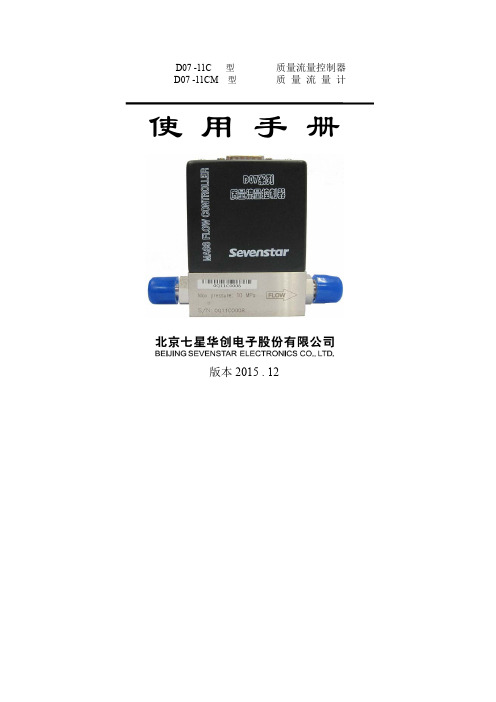
D07 -11C 型质量流量控制器D07 -11CM 型质量流量计使 用 手 册版本2015 . 12目录1. 使用须知.................................1 6.2.1 开机预热 . (16)2. 用途和特点..............................1 6.2.2 检查和调整零点 (16)3. 主要技术指标...........................3 6.2.3 通气工作 (16)4. 结构和工作原理........................4 6.2.4 关机 (16)4.1 结构.......................................47. 注意事项 (16)4.2 工作原理.................................57.1 禁用流量介质 (16)5. 安装和接线 ...........................77.2 使用腐蚀性气体问题 (17)5.1 外形及安装尺寸........................77.3 阀口密封问题 (17)5.2 气路接头形式...........................87.4 阀控操作注意 (17)5.3 连接电缆插头...........................97.5 安装位置问题 (17)5.4 与计算机信号的连接..................127.6 注意工作压差 (17)5.5 调零和外调零...........................137.7 标定和不同气体的换算 (18)6. 使用方法和操作步骤..................147.8 订货填写示例 (19)6.1 质量流量控制器的操作...............148. 故障判断和处理 (22)6.1.1 开机操作..............................149. 保证、保修与服务 (24)6.1.2 清洗功能..............................169.1 产品保证和保修.. (24)6.1.3 显示仪与计算机连接的操作......169.2 保修对使用的要求.. (24)6.1.4 直接与计算机连接的操作.........169.3 服务.. (24)6.1.5 阀控功能..............................1610. 附录.. (25)6.1.6 关机操作..............................1610.1 气体质量流量转换系数 (25)6.2 质量流量计的操作 ...................1610.2 转换系数使用说明 (27)MASS FLOW CONTROLLER & MASS FLOW METER第 1 页 共 27 页质量流量控制器和质量流量计使 用 手 册1. 使用须知尊敬的用户,感谢您购买本公司生产的D07系列质量流量控制器/质量流量计产品。
费托合成产物分布的实验研究
费托合成产物分布的实验研究林金芝;周利平;郝栩;杨勇;相宏伟;李永旺;靳海波【摘要】The traditional multiple-step collection of Fischer-Tropsch products was replaced by an one-step cooling method. The products (C1-C30 hydrocarbons and alcohols) in the gas phase were analyzed by the on-line GCs with high-temperature heating, while the liquids (C10-C70 hydrocarbons) were analyzed by the off-line GCs. The gases and the liquids were accurately measured by using internal standards, respectively. The work checked the accuracy and the stability of the high-temperature on-line analysis of the gas components. Some more reliable experimental results, e.g. the paraffins, olefins and alcohols formations catalyzed by an industrial iron-based catalyst, were given by this high-efficiency equipment.A correlation between the carbon number and the detailed products was developed. Furthermore, the work estimated the flash loss in product collecting and also the water condensation in the separator with the varied operating conditions by Aspen Plus modeling. It showed that the flash loss is negligible, and the water condensed in the separator, which will be mixed with the liquid wax, could enlarge the yields of the components inC10-C20 region. The separator running at higher temperature and lower pressure would be necessary to avoid the water condensation in the liquid wax.%将费托合成传统的多级冷却产物收集改进为一级冷却收集,气相产物(C1~C30烃和醇等)经高温管路直接在线分析,液相蜡(C10~C70烃类)离线分析,气相和液相产物均通过内标法精确计量。
- 1、下载文档前请自行甄别文档内容的完整性,平台不提供额外的编辑、内容补充、找答案等附加服务。
- 2、"仅部分预览"的文档,不可在线预览部分如存在完整性等问题,可反馈申请退款(可完整预览的文档不适用该条件!)。
- 3、如文档侵犯您的权益,请联系客服反馈,我们会尽快为您处理(人工客服工作时间:9:00-18:30)。
品牌:brooks
型号:5850E
类型:质量流量计
测量范围:0.03-30slpm(m3/h)
精度等级:1
公称通径:6(mm)
适用介质:专用气体工作压力:10(MPa)
工作温度:65(℃)
5850S/E气体质量流量计
美国BROOKS布鲁克斯公司热式质量流量计是为了满足有关工艺过程中对测量精度、重复性和控制方面
的要求而设计的产品。
它与传统的体积流量仪器截然不同,BROOKS质量流量计通过被测气体的比热来测量流量,不受温度、压力变化的影响。
因此该产品在各种不同的工作环境下均有较高的精度。
被测流量可设计成质量或体积单位。
此外,所有BROOKS INSTRUMENT质量流量计产品都能同现有的工业仪表兼容,安装简便。
技术参数:
数字信号/模拟信号输出,可通过电脑直接显示控制,可配单/四/八通道显示控制器
介质:可选H2,O2等非腐蚀性气体或SiO2,SO2等腐蚀性气体
流量范围:0.03-30slpm
最大工作压力:1500psi(10.432Mpa)
气路接头:1/4"VCR或1/4"SWG
电气接头:15Pins D-Type或Card-edge
精度:±1%FS
信号输出:RS-232/RS-485接口,4-20mA输出控制,TTL报警
内置微处理器,智能化、数字化。
软件组态,数字通讯,支持微软Windows动态数据交换。
流量范围:0-30L/MIN;
精度:1%FS;
最大压力:1500psi;
最高温度:65℃;
输入/输出:0-5V;
电源:+/-15V。
