Pneumatic Actuators
ACTUATECH气动执行器说明书

INSTRUCTION MANUALPart turn pneumatic actuatorwith Manual Override-Complete aluminium protection versionGDV60 - GDV3840 GSV30 – GSV19201)GENERAL FEATURES………………………………………………………………………………………………..pg.32)DATASHEET……………………………………………………………………………………………..pg.43)FUNCTIONAL DESCRIPTION……………………………………………..………….…………………….……………pg.54)DANGERS……….………………………………………………………………………………………..pg.75)PART DESCRIPTION……………..………………………………………………………….………………….pg.86)TRUOBLESHOOTING ………………………………………..…………………...…………………….pg.97)DISPOSAL…….………………...………………………………………………………..…………….....pg.9Environmentally friendly handling of the product.1)GENERAL FEATURES ••••••••••••••••••••••••••••••••••••••••••••••••••••••••••••••••••••••••••••••••••••••••••••••••••Actuatech manufacture a manual handwheel override for a wide range of part turn pneumatic actuators.The actuators with manual override are available on Double Acting “GDV” and Spring Return “GSV” versions.- The principle of the manual handwheel override application is to provide the possibility to open and close the valve connected to the actuator when this operation can’t be done with remote control.- Actuatech manual override actuator is itself equipped with an handwheel for manual operations and it doesn’t need any added declutchable gear box. This solution guarantees a compact size and a more light system on the valve.- When the actuator is manual operated it can be locked in Open/Closed position.- Actuator versions for low temperature and high temperature applications allow to operate respectively until temperatures of -50°C and +150°C, thanks to proper kind of lubrication and material for the gaskets.The maintenance should be done by Actuatech trained personnel only.This instruction manual contains important information regarding the Actuatech manual override actuator operation, installation, maintenance and storage.Please read carefully before installation and keep it in a safe place for further reference.Modification reserved. Rev.date 04/2018. No guarantee for accuracy. Older data sheets are invalid 2)DATASHEET•••••••••••••••••••••••••••••••••••••••••••••••••••••••••••••••••••••••••••••••••••••••••••••••••• DOUBLEACTINGNOMINALTORQUE (Nm)ISOFLANGESQUAREØHANDWEELRim pull forces ( N )To obtain thenominal torqueWeight( Kg )Teorical n° of turnsto close / openstarting from theneutral positionA B C DGDV60 60 F05-F07 14 180 19.3 2.8 11 - 99 263.3 137.6 GDV106 106 F05-F07 17 180 27.8 4 13 - 118.5 279.3 154.8 GDV120 120 F05-F07 17 180 33.8 4.5 14 - 122.1 288.4 163.9 GDV180 180 F07-F10 22 220 44.1 6 16 - 144.9 338.1 183.5 GDV240 240 F07-F10 22 220 54.5 8 18 - 156.8 353.7 199.1 GDV360 360 F07-F10 22 300 67.5 10.2 15 - 169.6 398 220.8 GDV480 480 F10-F12 27 300 83.3 13.2 16 - 193.8 440.6 236.4 GDV720 720 F10-F12 27 350 108.8 17.8 19 - 216.6 503.5 282.3GDV960 960 F10-F12 /F1436 350 128.6 23.8 20 - 239.7 518.3 297.1 GDV1440 1440 F12 / F14 36 400 133.5 33.6 25 - 283.5 636.4 365.6GDV1920 1920 F12-F16 /F1446 400 162.5 43 26 - 300.4 653.7 382.9 GDV3840 3840 F16 46 575 243.5 75 30 - 353.3 890.2 537.5SIMPLEACTINGNOMINALTORQUE (Nm)ISOFLANGESQUAREØHANDWEELRim pull forces ( N )To obtain thenominal torqueWeight( Kg )Teorical n° of turnsto close / openstarting from theneutral positionA B C DGSV30 30 F05-F07 14 180 19.3 3.2 11 129.4 - 263.3 137.6 GSV053 53 F05-F07 17 180 27.8 4.5 13 152.1 - 279.3 154.8 GSV060 60 F05-F07 17 180 33.8 4.5 14 169.3 - 288.4 163.9 GSV090 90 F07-F10 22 220 44.1 6.8 16 196.8 - 338.1 183.5 GSV120 120 F07-F10 22 220 54.5 9 18 204.8 - 353.7 199.1 GSV180 180 F07-F10 22 300 67.5 11.7 15 237 - 398 220.8 GSV240 240 F10-F12 27 300 83.3 15.2 16 260.2 - 440.6 236.4 GSV360 360 F10-F12 27 350 108.8 19.5 19 306.6 - 503.5 282.3GSV480 480 F10-F12 /F1436 350 128.6 28.1 20 324.1 - 518.3 297.1GSV720 720 F12 / F14 36 400 133.5 38.8 25 399 - 636.4 365.6GSV960 960 F12-F16 /F1446 400 162.5 50.6 26 414 - 653.7 382.9GSV1920 1920 F16 46 575 243.5 91 30 509 - 890.2 537.5 All the dimensions are in mm, for missing data see standard catalogue .Modification reserved. Rev.date 04/2018. No guarantee for accuracy. Older data sheets are invalid3) FUNCTIONAL DESCRIPTION •••••••••••••••••••••••••••••••••••••••••••••••••••••••••••••••••••••••••••••••••••••••••••••••••• NB: PRIOR TO MANUAL OVERRIDE OPERATE, ENSURE THAT THE ACTUATOR IS FREE FROM PRESSURE.1.Remove the cap to ensure there is no pressure in the actuator2.Engage the manual override and operate as required3.Disconnect the manual override (neutral position)*for standard actuators.TO CLOSE THE VALVETo close the valve turn the wheel in clockwise direction*.TO OPEN THE VALVETo open the valve turn the wheel in counterclockwise direction.* NB: Before commissioning to ensure proper disengagement, perform an ON-OFF maneuver of the actuatorModification reserved. Rev.date 04/2018. No guarantee for accuracy. Older data sheets are invalidNB: WHEN THE ACTUATOR HAS BEEN MANUALLY OPERATED, RETURN TO THE NEUTRAL POSITION PRIOR TO START NORMAL OPERATIONS.NEUTRAL POSITIONWith the screw in neutral position the piston can move freely and the actuator can be driven pneumatically. MANUAL OPERATION GDV : The handwheel turned counter clockwise, pushes the screw and piston inwards. The valve opens. GSV : The handwheel turned clockwise pushes the screw and piston inwards. The valve closes.MANUAL OPERATIONGDV : When the handwheel is turned clockwise, the screwand piston are drawn outwards. The valve closes. GSV : When the handwheel is turned counter clockwise, the screw and the piston are drawn outwards. The valve opens.Modification reserved. Rev.date 04/2018. No guarantee for accuracy. Older data sheets are invalid4)WARNINGS •••••••••••••••••••••••••••••••••••••••••••••••••••••••••••••••••••••••••••••••••••••••••••••••••• a) Don’t disassemble, compressed spring inside.b) Don’t use levers or bars.c) Don’t use the handwheel to lift the actuator.NB:Manual override is not recommended for safety related applications (SIL) as bypass of a security function. In this application, to prevent an unauthorized use, the manual override is provided with a locking device.Modification reserved. Rev.date 04/2018. No guarantee for accuracy. Older data sheets are invalid5)PART DESCRIPTION ••••••••••••••••••••••••••••••••••••••••••••••••••••••••••••••••••••••••••••••••••••••••••••••••••NB: In the case of actuator low or high temperature the pistons and the material of the O ring are different from the standard actuator.Modification reserved. Rev.date 04/2018. No guarantee for accuracy. Older data sheets are invalid6)TROUBLESHOOTING •••••••••••••••••••••••••••••••••••••••••••••••••••••••••••••••••••••••••••••••••••••••••••••••••• POTENTIAL EFFECT OFFAILUREPOTENTIAL CAUSE OF FAILURE SOLUTION Difficult manual operationsBlocked valve Repair or replace the valvePresence of particles inside the actuator due toan incorrect filtration of the airVerify the condition of the supply airand contact ActuatechThe actuator is pressurized Remove supply air7)DISPOSAL •••••••••••••••••••••••••••••••••••••••••••••••••••••••••••••••••••••••••••••••••••••••••••••••••• Our products are designed so that when they are at the end of their life cycle they can be completely disassembled, separating the different materials for the proper disposal and/or recovery. All materials have been selected in order to ensure minimal environmental impact, health and safety of personnel during their installation and maintenance, provided that, during use, they are not contaminated by hazardous substances.The personnel in charge of the product disposal/recovery, must be qualified and equipped with appropriate personal protective equipment (PPE), according to the product size and the type of service for which the device was intended. The management of waste generated during the installation, maintenance or due to the product disposal, is governed by the rules in force in the country where the product is installed, in any case, the following are general guidelines:- The metal components (aluminum/steel) can be restored as raw material;- Seals/sealing elements as contaminated by fluids from other materials and lubrication,must be disposed of.- The packaging materials that come with the product, should be transferred to the differentiated collection systemavailable in the country.。
三位一体电气双向阀门产品参数说明书

VISIT OUR WEBSITES: • • .auSeries 3ABVAutomated Ball Valve - 3-Way Brass NPTElectric and Pneumatic ActuatorsSPECIFICATIONSService:Compatible liquids, gases or steam.Body:3-way.Line Size:1/4˝ to 2˝.End Connections:Female NPT.Pressure Limits:1/4˝ to 1-1/4˝: 435 psi (30 bar) WOG; 1-1/2˝: 232 psi (16 bar)WOG; 2˝: 145 psi (10 bar) WOG. 100 psi (6.9 bar) SWP .Wetted Materials:Body, end cap, stem:Brass; Ball: Brass, chrome plated; Seat,stem seal: TFE.Temperature Limits:320°F (160°C).Other Materials:Body seal, body O-ring, stem O-ring: Fluoroelastomer.ACTUATORS Electric Power Requirements: 120 VAC, 50/60Hz, single phase. Optional 220 VAC, 24VAC, 12 VDC, and 24 VDC.Power Consumption (Locked Rotor Current):Two position: 1/4˝ to 3/4˝: .55A,1˝ to 2˝: .75A; Modulating: 1/4˝ to 3/4˝:.55A, 1˝ to 2˝: .75A.Cycle Time:(per 90°): Two position: 1/4˝to 3/4˝: 2.5 sec., 1˝ to 2˝: 5 sec.;Modulating: 1/4˝ to 3/4˝: 2.5 sec., 1˝ to 2˝:5 sec.Duty Cycle:Two position: 1/4˝ to 3/4˝:75%, 1˝ to 2˝: 25%; Modulating: 75%.Enclosure Rating:NEMA 4. Optional NEMA 7.Housing Material: Aluminum with thermal bonding polyester powder finish.Temperature Limit:0 to 150°F (-18 to 65°C).Conduit Connection:1/2˝ female NPT.Modulating Input:4 to 20 mA.Standard Features:Manual override and visual position indicator except modulating units.Pneumatic “DA” and “SR” SeriesType: DA series is double acting and SR series is spring return (rack and pinion).Normal Supply Pressure:80 psi (5.5 bar).Maximum Supply Pressure:120 psig (8 bar).Air Connections:DA/SR1 to 5: 1/8˝ female NPT, all other sizes: 1/4˝ femaleNPT.Air Consumption:(per stroke) DA1:2.32 cu. in.; DA2, SR2: 9.34 cu. in.; DA3,SR3: 17.21 cu. in.; DA4, SR4: 20.5 cu.in.; SR5: 39.54 cu. in. Cycle Time: (per 90°) DA1: .03 sec.;DA2: .04 sec.; DA3: .08 sec.; DA4: .12sec.; SR2: .09 sec.; SR3: .14 sec.; SR4:.22 sec.; SR5: .33 sec.Housing Material:Anodized aluminum body and epoxy coated aluminum end caps.Temperature Limit:-4 to 180°F (-20 to 82°C).Accessory Mounting: NAMUR standard.Standard Features:Visual position indicator.The Series 3ABV incorporates a standard port valve for great flow rates with minimalpressure drop. Features include a blowout proof stem for added safety and reinforced TFE seats and seals for longer life and leak-free operation. The four seat design allows for high cyclic capabilities and tight shut-off in any position. Perfect for mixing or diverting services in the food and chemical processing industries.The 3ABV is an economical automated valve package with either an electric or pneumatic actuator. Electrically actuated models are weatherproof, NEMA 4, powered by standard 115VAC supply, and are available in either two-position or proportional control. Two-position actuators use the 115 VAC input to drive each of the valve ports open or closed, while the modulating actuator accepts a 4-20 mA input for infinite valve positioning. Actuator features include thermal overload protection to withstand stall conditions, visual position indication,and a permanently lubricated gear train.The pneumatic double acting actuator uses an air supply to drive each of the actuator ports.Spring return pneumatic actuators use the air supply to drive the valve stem in one direction,and internally loaded springs return the valve to its original position. Also available is the SV3 solenoid valve to electrically switch the supply pressure between the air supply ports.Actuators are constructed of anodized aluminum and are epoxy coated for years of corrosion free service.How To Order:1. Select Model No.to specify pipe size and actuator.2. Choose a Port Configuration to determine valve flow path.Example:3ABV1DA204-T2Optional Electric Actuator Supply Voltages-Contact factory for model number changeSolenoid Valve -See Model SV3.。
气动执行器加工工艺流程
气动执行器加工工艺流程The production process of pneumatic actuators plays a vital role in ensuring their quality and performance. 气动执行器的生产工艺流程对于保证其质量和性能至关重要。
From the initial design stage to the final assembly and testing, each step must be carefully planned and executed to meet all the necessary requirements. 从最初的设计阶段到最终的装配和测试,每个步骤都必须经过精心规划和执行,以满足所有必要的要求。
Only with a well-defined and efficient production process can high-quality pneumatic actuators be manufactured. 只有通过明确定义且高效的生产流程,才能制造出高质量的气动执行器。
The first step in the production process of pneumatic actuators is the design phase. 气动执行器生产工艺的第一步是设计阶段。
During this stage, engineers and designers work together to develop a detailed blueprint of the actuator, taking into account factors such as size, shape, and material. 在这个阶段,工程师和设计师共同努力,制定出执行器的详细蓝图,考虑因素包括尺寸、形状和材料。
Flowserve S Series SuperNova Pneumatic Actuator说明书

Automax SuperNova Series Pneumatic Rack & Pinion ActuatorsThe Flowserve S Series SuperNova pneumatic actuator is the latest development of the product, which has won worldwide praise for its reliability, versatility and safety.Rugged, yet compact construction, combined with new technical solutions make this product extremely reliable in the severest of operating conditions. Furthermore, an entire range of accessories manufactured by Flowserve Automax, enables users to rely on a single partner for all their valve automation system components.The Automax actuator’s prime function is to generate a torque out-put to turn valves or other rotary equipment. As such it is not deemed a pressure vessel or machine. Pneumatic actuators of these sizes are not governed by the demands of the PED.1Top and bottom pinion bearings designed to withstand the toughest working conditions.2Steel pinion with ultra resistant Nitride surface treatment.3Adjustable open & closed travel-stops.4Concentric springs with over 10 years of proven reliability.5Stainless steel fastenings throughout, for long-term corrosion resistance.ISO 5211/DIN 3337 for valve connection (STAR DRIVE).NAMUR (VDI/VDE 3845) for solenoid valve connection.NAMUR (VDI/VDE 3845) for limit switch, positioner andother accessories.31A BSIL 2 (IEC 61508)94/9/ECMAIN FEATURES•Aluminium alloy body, internally and externally hard anodised.•End caps, oven-treated with ultra-thick epoxy coating.•Fully field reversible for altering spring failure mode.•Piston guide bearings with wide contact surfaces, increased efficiency and cycle life.•Independent open and closed adjustment (standard across S050-S200) is indispensable where finite adjustment or limited rotation is required.•Working temperatures to cover from -50°C to +150°C.Standard -20°C to +80°C.•The unique design also allows for operation with non-lubricated air.•Maintanable on site without the need for any special tools.•Valve and accessory connections according to the latest international standards:Spring ConfigurationsSpring markings: #1 Spring = 1 colour code dot #2 Spring = 2 colour code dots #3 Spring = 3 colour code dotsMODEL S050 SPRING CHARTSpring CombinationStandard Spring Set# 1 Spring # 2 Spring # 3 SpringConfigurations(inner )(low rate outer )(high rate outer )(air supply )0411052 3 bar 0621 4 bar 0712 5 bar 08225.5 bar0922MODEL S063-S200 SPRING CHARTSpring CombinationStandardSpring Set# 1 Spring # 2 Spring # 3 SpringConfigurations(inner )(low rate outer )(high rate outer )(air supply )0420511 3 bar0620712 4 bar 0822 5 bar 091121022 5.5 bar 1112212222THE PRODUCT RANGE INCLUDES THE FOLLOWING OPTIONS:•Temperatures from -50°C to +80°C (Low temperature),-20°C to +150°C (High temperature).•Stainless steel pinion.•Body with dual ISO 5211 mounting connections.•180° rotation plus options up to 250°.(technical and dimension data available on request)•Fast acting version with G½ ports on body / end caps.•MaxGuard™ - special coating for corrosive and aggressive applicationsDouble Acting VersionTorque Outputs (Nm) - Spring Return Actuator (S050 - S200)Torque Outputs (Nm) - Double Acting Actuator (S050 - SN300)The diagrams below show typical torque curves for rack & pinion actuators.As seen in the graph, the double acting actuator has constant torque over the whole travel, so that all that needs to be known for sizing is the maximum static torque required by the valve, which is multiplied by a safety coefficient (usually between 25% and 50% depending on the type of valve). The value thus obtained is then compared with the figures in the minimum air pressure column in the torque table. Having found the same or nearest value (in excess), the suitable model can be read off the column to the left.The spring return actuator, on the other hand, has four torques: springbreak , pneumatic break (usually the same) pneumatic end and spring end (usually the same). Choice of actuator here depends on various factors (valve type, normally open or closed) and the method is usually the same as that of double acting models, except that the value must be compared with the lower of spring and pneumatic end . The value of the springs can in any case be modified to adapt the actuator’s torque to the value required by the valve.DOUBLE ACTING%2040608010045°AIRSPRING RETURN%2040608010045°Torque %AIRSPRINGSTorque Outputs (Nm) - Spring Return Actuator (SN250 - SN300)Parts & Materials Lists S050 - S20019820109138112242322326754a42712* Parts Included in Repair KitParts & Materials List SN250 - SN300* Parts Included in Repair KitDimensions S050 - S200Dimensions SN250 - SN300NOTE: For optional G½ Inlet Block, order separately using code 428132Automax Actuator Coding Operating ConditionsMedia Air or non-corrosive fluid.The media should have a dew point at least10°C below the ambient operating temperature.Temperature Range Standard -20°C to +80°CLow temperature variant -50°C to +80°CHigh temperature variant -20°C to +150°CRotation Pinion rotates anti-clockwise when the centre(viewed from top)chamber supply port (RHS) is pressurised.Reverse acting options available.Travel Average 100° total travel to provide nominal(all sizes)5° over travel clockwise and anti clockwise.SN250/SN300 models - travel stops in outwarddirection only.Extended Travel180°, 140°, 120°. For further options consultyour local Flowserve sales operation.Adjustable Travel Stop Standard on all 90° versions.Optional on 140°.Open adjustment only on 180°.Complete Valve Automation Systems- 11 -WATERPROOF LIMIT SWITCH BOXEXPLOSIONPROOF LIMIT SWITCH BOXPOSITIONERPHAROS POSITIONINDICATORDECLUTCHABLE MANUALOVERRIDENAMUR SOLENOIDVALVECENTRE RING (OPTIONAL)NAMUR - QUICK EXHAUST, LOCK OUT & VENT AND SPEED CONTROLBLOCKS AVAILABLEFC-SR FC-DAINDICATORDue to continuous development of our product range, we reserve the right to alter the dimensions and information contained in this leaflet as required. Information given in this leaflet is made in good faith and based upon specific testing but does not, however, constitute a guarantee.Automax Main Operations United KingdomBurrell Road, Haywards Heath, West Sussex, England RH16 1TL Telephone: +44 (0) 1444 314 400 Fax: +44 (0) 1444 314 401 GermanyFlowserve Limburg,Im grossen Rohr 2,D-65549 Limburg/Lahn Telephone: +49 (0)6431 9661 0 Fax: +49 (0)6431 9661 30ItalyFlowserve Spa, Via Prealpi, 30 20032 Cormano (Milano) Telephone: +39 (0)2 663251 Fax: +39 (0)2 6151863 NetherlandsFlowserve Flow Control B.V. Rechtzaad 17, 4703 RC Roosendaal Telephone: +31 (0)165 598800 Fax: +31 (0)165 555670USA1978 Foreman Drive, Cookeville, TN 38501 USA Telephone: +1 931 432 4021 Fax: +1 931 431 3105Asia Pacific12 Tuas Avenue 20, 638824 Republic of Singapore Telephone: +65 862 3332Fax: +65 862 4940Local Automax Offices Australia14 Dalmore DriveScoresby Road, Victoria 3179 Telephone: +43 (0) 42 4241 1810 Fax: +43 (0) 42 4241 181 50/51 IndiaPlot No. 4, EPIPWhitefield, Bangalore - 560066 Tel: +91 (0)80 28410 289/293 Fax: +91 (0)80 28410 286/287 South AfricaUnit 1, 12 Director RoadSpartan Ext. 2Kempton Park, Gauteng Telephone: +27 (0)11 923Fax: +27 (0)119 746 420。
阀门名词术语中英文对照

阀门名词术语中英文对照阀门 valve闸阀 gate valve截止阀 globe valve, stop valve节流阀 throttle valve球阀 ball valve蝶阀 butterfly valve隔膜阀 diaphragm valve旋塞阀 plug valve止回阀 check valve, non-return valve安全阀 safety valve, pressure减压阀 pressure reducing valve疏水阀 steam trap排污阀 blow-down valve调节阀 (控制阀)control valve, adjusting valve 分配阀 dividing valve混合阀 mixing valve水力控制阀 hydraulic control valve手动阀门 manual operated valve电动阀门 electrical operated valve气动阀门 pneumatically operated valve低压阀门 low pressure valve中压阀门 middle pressure valve高压阀门 high pressure valve超高压阀门 super high pressure valve高温阀门 high temperature valve中温阀门 moderate temperature valve常温阀门 normal temperature valve低温阀门 sub-zero valve超低温阀门 cryogenic valve结构长度 face-to-face dimension结构形式 type of construction直通式 through way type角式 angle type直流式 y-type三通式 three way typeT形三通式 T-pattern three wayL形三通式 L-pattern three way平衡式 balance type杠杆式 lever type常开式 normally open type 常闭式 normally closed type保温式 steam jacket type波纹管式 bellows seal type全径阀门 full-port valve缩径阀门 reduced-port valve缩口阀门 reduced-bore valve单向阀门 unidirectional valve双向阀门 bidirectional valve上密封 back seal压力密封 pressure seal连接形式 type of connection壳体 shell阀体 body阀盖 bonnet启闭件 disc阀座 seat密封面 sealing face,surface阀杆 stem, spindle阀杆螺母 yoke nut填料函(填料箱) stuffing box填料 packing, packing rings填料垫 packing seat, packing washer支架 yoke撞击手轮 impact hand wheel阀瓣(阀芯) disc(valve core)楔式闸阀 wedge gate valve闸板 wedge单闸板 single gate刚性闸版 rigid gate弹性闸板 flexible gate disc双闸板 double gate楔式双闸板 wedge double gate平行式双闸板 parallel double gate浮动式球阀 floating ball valve固定式球阀 fixed ball valve球体 ball斜板式蝶阀 inclined disc butterfly valve 蝶板 disc屋脊式隔膜阀 weir diaphragm valve截止式隔膜阀 globe diaphragm valve隔膜 diaphragm填料式旋塞阀 gland packing plug valve 油封式旋塞阀 lubricated plug valve塞子 plug升降式止回阀 lift check valve升降立式止回阀 vertical lift check valve 旋启式止回阀 swing check valve底阀 foot valve,bottom valve轴流式止回阀 axial flow check valve蝶式止回阀 butterfly swing check valve 销轴 hinge pin摇杆 arm先导式安全阀 pilot operated safety valve 全启式安全阀 full lift safety valve微启式安全阀 low lift safety valve双联弹簧式安全阀 duplex safety valve真空安全阀vacuum relief valve敞开式安全阀 openly sealed safety valve 调节螺母 adjusting screw弹簧座 spring plate导向套 dise guide反冲盘 disc holder调节圈 adjusting ring压力释放装置pressure relief device爆破片装置bursting disk device折断销装置breaking pin device弯折销装置buckling pin device剪切销装置shear pin device易熔塞装置fusible plug device排放面积discharge area流道面积flow area流道直径flow diameter帘面积curtain area开启高度lift额定开高rated lift密封面斜角seat angle密封面积seat area密封面平均直径seat mean diameter净流通面积net flow area喉径 throat diameter整定压力set pressure超过压力overpressure回座压力reseating pressure启闭压差blowdown排放压力 relieving pressure排放背压力 built-up back pressure附加背压力 superimposed back pressure理论排量 theoretical discharge capacity 额定排量 certified (discharge) capacity 频跳 chatter颤振 flutter封闭式 seal type非封闭式 unseal type在用试验in-service testing工作台上定压试验bench testing薄膜式减压阀 diaphragm reducing valve活塞式减压阀 piston reducing valve杠杆式减压阀 lever reducing valve膜片 diaphragm浮球式疏水阀 ball float steam trap浮桶式疏水阀 open bucket steam trap脉冲式疏水阀 impulse steam trap热动力式疏水阀 thermodynamic steam trap 蒸汽疏水阀 steam trap工作压力 operating pressure最高工作压力 maximum operating pressure 最低工作压力 minimum operating pressure 工作背压 operating back pressure背压率 rate of back pressure最大压差 maximum differential pressure最小压差 minimum differential pressure开阀温度 operating valve temperature关阀温度 closing valve temperature过冷度 subcooled temperature最小过冷度 minimum subcooled temperature 冷凝结水排量 cold condensate capacity热凝结水排量 hot condensate capacity漏汽量 steam loss无负荷漏汽量 unload steam loss 有负荷漏汽量 load steam loss无负荷漏汽率 rate of unload steam loss有负荷漏汽率 rate of load steam loss负荷率 rate of load condensate阀片 disc钟形罩 inverted bucket浮球 float ball浮桶 float bucket执行机构 actuator基本误差 intrinsic error回差 hysteresis error死区 dead band行程 travel额定行程 rated travel相对行程(h) relative travel(h)额定行程偏差 deviation of rated travel额定流量(Q) rated flow(Q)泄漏量 leakage流量系数 flow coefficient额定流量系数(K V)rated flow coefficient(K V)相对流量系数(Φ)relative flow coefficient(Φ)固有流量特性 inherent flow characteristic可调比(R) inherent rangea bility(R)阻塞流 choked flow斜率偏差 slope deviation遥控浮球阀 remote float control valve水利控制减压阀 pressure reducing valve缓闭止回阀 low speed closed check valve 持压/泄压阀 pressure sustaining ,relief valve 水泵控制阀 pump control valve最小开启压力 minimum open pressure驱动装置 actuator多回转驱动装置 multi-turn actuator部分回转驱动装置 part-turn actuator电动装置 electric actuator气动装置 pneumatic actuator直线型气动装置 linear pneumatic actuator回转型气动装置 rotary pneumatic actuator气动装置的行程 stroke of pneumatic actuator 液压驱动装置 hydraulic actuator电磁驱动装置 electro magnetic actuator 电-液联动装置 electro hydraulic actuator气-液驱动装置 pneumatic-hydraulic actuator 蜗轮传动装置 worm gear actuator正齿轮传动装置 cylindrical gear actuator 锥齿轮传动装置 conical gear actuator转矩 torque推力 thrust壳体试验 shell test壳体试验压力 shll test pressure密封试验 seal test密封试验压力 seal test pressure上密封试验 back seal test静压寿命试验potential pressure life test耐火试验 fire test防静电试验 anti-static test主要性能参数 specification公称压力 nominal pressure公称尺寸 nominal diameter工作压力 working pressure最高工作压力 maximum operating pressure 工作温度 working temperature最高工作温度 maximum operating temperature 泄漏量 leakage吻合度 percent of contact area连接尺寸 connection dimension最大压差 maximum pressure differential 位置指示器 position indicator压力边界 pressure boundaryWelcome !!!欢迎您的下载,资料仅供参考!。
Robots机器人 中英文翻译
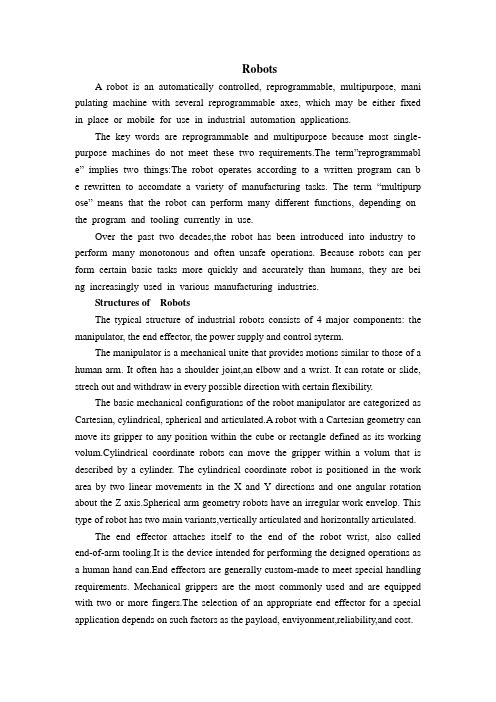
RobotsA robot is an automatically controlled, reprogrammable, multipurpose, mani pulating machine with several reprogrammable axes, which may be either fixed in place or mobile for use in industrial automation applications.The key words are reprogrammable and multipurpose because most single-purpose machines do not meet these two requirements.The term”reprogrammabl e” implies two things:The robot operates according to a written program can b e rewritten to accomdate a variety of manufacturing tasks. The term “multipurp ose” means that the robot can perform many different functions, depending on the program and tooling currently in use.Over the past two decades,the robot has been introduced into industry to perform many monotonous and often unsafe operations. Because robots can per form certain basic tasks more quickly and accurately than humans, they are bei ng increasingly used in various manufacturing industries.Structures of RobotsThe typical structure of industrial robots consists of 4 major components: the manipulator, the end effector, the power supply and control syterm.The manipulator is a mechanical unite that provides motions similar to those of a human arm. It often has a shoulder joint,an elbow and a wrist. It can rotate or slide, strech out and withdraw in every possible direction with certain flexibility.The basic mechanical configurations of the robot manipulator are categorized as Cartesian, cylindrical, spherical and articulated.A robot with a Cartesian geometry can move its gripper to any position within the cube or rectangle defined as its working volum.Cylindrical coordinate robots can move the gripper within a volum that is described by a cylinder. The cylindrical coordinate robot is positioned in the work area by two linear movements in the X and Y directions and one angular rotation about the Z axis.Spherical arm geometry robots have an irregular work envelop. This type of robot has two main variants,vertically articulated and horizontally articulated.The end effector attaches itself to the end of the robot wrist, also called end-of-arm tooling.It is the device intended for performing the designed operations as a human hand can.End effectors are generally custom-made to meet special handling requirements. Mechanical grippers are the most commonly used and are equipped with two or more fingers.The selection of an appropriate end effector for a special application depends on such factors as the payload, enviyonment,reliability,and cost.The power supply is the actuator for moving the robot arm, controlling the joints and operating the end effector. The basic type of power sources include electrical,pneumatic, and hydraulic. Each source of energy and each type of motor has its own characteristics, advantages and limitations. An ac-powered motor or dc-powered motor may be used depending on the system design and applications. These motors convert electrical energy into mechanical energy to power the robot.Most new robots use electrical power supply. Pneumatic actuators have been used for high speed. Nonservo robots and are often used for powering tooling such as grippers. Hydraulic actuators have been used for heavier lift systems, typically where accuracy was not also requied.The contro system is the communications and information-processing system that gives commands for the movements of the robot. It is the brain of the robot; it sends signals to the power source to move the robot arm to a specific position and to the end effector.It is also the nerves of the robot; it is reprogrammable to send out sequences of instructions for all movements and actions to be taken by the robot.A open-loop controller is the simplest for of the control system, which controls the robot only by foolowing the predetermined step-by-step instructions.This system dose not have a self-correcting capability.A close-loop control system use feedback sensors to produce signals that reflct the current states of the controed objects. By comparing those feedback signals with the values set by the programmer, the close-loop controller can conduct the robot to move to the precise position and assume the desired attitude, and the end effector can perform with very high accuracy as the close-loop control system can minimize the discrepancy between the controlled object and the predetermined references.Classification of RobotIndustrial robots vary widely in size,shape, number of axes,degrees of freedom, and design configuration. Each factor influence the dimensions of the robot’s working envelop or the volume of space within which it can move and perform its designated task. A broader classification of robots can been described as below.Fixed-and Variable-Sequence Robots. The fixed-sequence robot (also called a pick-and place robot) is programmed for a specific sequence of operations. Its movements are form point to point, and the cycle is repeated continuously.The variable-sequence robot can be programmed for a specific sequence of operations but can be programmed to perform another sequence of operation.Playback Robot. An operator leads or walks the playback robot and its end effector through the desired path. The robot memorizes and records the path and sequence of motions and can repeat them continually without any further action or guidance by the operator.Numerically Controlled Robot. The numerically controlled robot is programmed and operated much like a numerically controlled machine. The robot is servocontrolled by digital data, and its sequence of movements can be changed with relative ease.Intelligent Robot. The intelligent robot is capable of performing some of the functions and tasks carried out by huanbeings.It is equipped with a variety of sensors with visual and tactile capabilities.Robot ApplicationsThe robot is a very special type of productin tool; as a result, the applications in which robots are used are quite broad. These applications can be grouped into three categories: material processing, material handling and assembly.In material processing, robots use tools to process the raw material. For example, the robot tools could include a drill and the robot would be able to perfor drilling operaytions on raw material.Material handling consists of the loading, unloading, and transferring of workpieces in manufacturing facilities. These operations can be performed relatively and repeatedly with robots, thereby improving quality and scrap losses.Assembly is another large application area for using robotics. An automatic assembly system can incorporate automatic testing, robot automation and mechanical handling for reducing labor costs, increasing output and eliminating manual handling concers.机器人机器人是一种自动控制的、可重复编程的、多功能的、由几个可重复编程的坐标系来操纵机器的装置,它可以被固定在某地,还可以是移动的以在工业自动化工厂中使用。
Remote Control RC200 Pneumatic Actuator说明书
Product Overviewwww.remotecontrol.se2011-01-10Pneumatic RC200ActuatorsROTORK SWEDEN ABBox 80, Kontrollvägen 15, SE-791 22 Falun SwedenTel+46(0)23-58700•Fax:+46(0)23-58745•*********************Example:RC210-SRBMF050HESURFACE TREATMENTBL=BlueE=EpoxyR=Red (Standard, not marked)SPECIAL DESIGNH=HydraulicsHT=High tempAC=Fully adjustable in closed positionAO=Fully adjustable in open positionLT=Low tempPD=Piston in ductile ironQ=Quick operatingS=Stainless shaft + screw + ciclipWH=Water hydraulicsSPRING PRESSURE020-100=20psi - 100psiSPRING FUNCTIONF=Spring opens (Fail open)MANUAL OVERRIDEM=M1M2=M2SHAFT TYPEA=A-shaft (Standard, not marked)B=B-shaftC=Key grooveFUNCTIONDA=Double actingSR=Spring returnSIZE10 - 100MODELRC=Terminated model RC05-80RC2=RC200 seriesRCA=Stainless steel actuatorRCC=Steel actuatorRCD=DIN actuatorRCE=Electro-hydraulic actuatorRCI=RCI actuatorRCT=Actuator with reinforced corrosion protectionRCR=180 - Degree actuatorRCG=Cast steel actuator2Product OverviewConversion TableFor RC Actuators2011-01-10 RC210 -SR B M F050H EPageConversion Table 2 Contents 3 Torque figures4 RC200 Actuator acc to DIN/ISO standard5 RC200 Actuators according to DIN/ISO standard with manual override M16 RCT200 Actuator Reinforced corrosion protection with stainless outer parts7 RCT200 Actuators Reinforced corrosion protection and manual override unit M18 RC 88 / RCT88 Actuators9 Spare Parts10 Limit switches RCE4L 11 Limit switches IND12 Limit switches Explosion proof design 13 Positioners 14 RCC-Firesafe15 Solenoid valves Namur 16 Solenoid valves Accessories 17 Mounting kits Stainless steel18 Mounting kits / Reducers Painted carbon steel19 Mounting kits for 3-piece ball valves without mounting flange 20 Telephone E-mail213Product OverviewContents2011-01-10Double acting actuators DA210-DA220-DA 230-DA 240-DA 250-DA 260-DA 265-DA 270-DA 280-DA 88-DA90-DA100-DA0° = Closed positionConversion table Torque1 Nm = 0,102 kpm = 8,85 Ib.in.1 kpm = 9,81 Nm = 86,8 Ib.in.1 Ib.in = 0,113 Nm = 0,0115 kpm Pressure1 Mpa = 10 bar = 10,2 kp/cm² = 145 psi47400357054001525072001135038001900274076003800548012966099211890940136045022532091046065014572105290145210381927763854Product OverviewTorque figuresSizeTorque in Nm at valve position Air pressure 0,6 Mpa (6 bar / 87 psi)0°50°90°2011-01-10CE marking according to ATEX Directive 94/9/EC (class II 2GD)RC270-RC88 CE marking according to PED 97/23/EG module A RC200-DA ModelOrder No Torque (Nm)RC210-DA F05-1411325238RC220-DA F05-1412310176RC230-DA F07-17133095145RC240-DA F10-22143096290RC250-DA F10-22153316450RC260-DA F12-27163245910RC265-DA F12-271650071231RC270-DA F14-361732141890RC280-DA F16-461832553800RC200-SR (spring pressure 6 bar = 87 psi)Model Order No Torque (Nm)RC210-SR087 F05-1411325720/12RC220-SR087 F05-1412310641/25RC230-SR087 F07-17 13309878/47RC240-SR087 F10-22 143099158/96RC250-SR087 F10-22 153319245/150RC260-SR087 F12-27 163248500/305RC265-SR087 F12-27165008673/412RC270-SR087 F14-361732181030/620RC280-SR087 F16-461832592080/1260RC210-SRF087 F05-1411325822/15RC220-SRF087 F05-1412310844/30RC230-SRF087 F07-17 13310283/57RC240-SRF087 F10-22 143104170/115RC250-SRF087 F10-22 153323260/180RC260-SRF087 F12-27 163252530/360RC265-SRF087 F12-27 165020696/416RC270-SRF087 F14-361732221090/750RC280-SRF087 F16-461832632230/1510SR = Spring closes SRF = Spring opensOther spring combinations (4 bar = 60 psi and 7 bar = 100 psi) on request.Torque is given at 0° opening / 0° closing.5Product OverviewRC200 Actuatoracc to DIN/ISO standard2011-01-10RC200-DAM with manual override M1ModelArticle No Torque (Nm)RC210-DAM F05-1411325438RC220-DAM F05-1412310276RC230-DAM F07-17133112145RC240-DAM F10-22 143108290RC250-DAM F10-22153333450RC260-DAM F12-27 163247910RC265-DAM F12-271650181231RC270-DAM F14-361732161890RC280-DAM F16-461832583800RC200-SRM with manual override M1 (spring pressure 6 bar = 87 psi)Model Article No Torque (Nm)RC210-SRM087 F05-1411326420/12RC220-SRM087 F05-1412311341/25RC230-SRM087 F07-1713310478/47RC240-SRM087 F10-22 143106158/96RC250-SRM087 F10-22 153325245/150RC260-SRM087 F12-27 163254500/305RC265-SRM087 F12-27165012673/412RC270-SRM087 F14-361732241030/620RC280-SRM087 F16-461832662080/1260RC210-SRMF087 F05-1411328622/15RC220-SRMF087 F05-1412315044/30RC230-SRMF087 F07-17 13310583/57RC240-SRMF087 F10-22 143107170/115RC250-SRMF087 F10-22 153326260/180RC260-SRMF087 F12-27 163256530/360RC265-SRMF087 F12-27165021696/416RC270-SRMF087 F14-361732251090/750RC280-SRMF087 F16-461832672230/1510Bracket for locking the handwheel with padlock Model Article No Bracket for locking RC210-220259226Bracket for locking RC230-240259227Bracket for locking RC250-260259228Bracket for locking RC265259350Bracket for locking RC270-280259327SRM = Spring closes SRMF = Spring opensOther spring combinations (4 bar = 60 psi and 7 bar = 100 psi) on request.Torque is given at 0° opening / 0° closing.6Product OverviewRC200 Actuatorsaccording to DIN/ISO standard with manual override M1RC270-RC88 CE marking according to PED 97/23/EG module ACE marking according to ATEX Directive 94/9/EC (class II 2GD)2011-01-10RCT200-DA. Reinforced corrosion protection Model Order No Torque (Nm)RCT210-DA F05-1411325638RCT220-DA F05-1412310476RCT230-DA F07-17 133111145RCT240-DA F10-22 143114290RCT250-DA F10-22 153332450RCT260-DA F12-27 163258910RCT265-DA F12-27 1652301231RCT270-DA F14-361732261890RCT280-DA F16-461832683800RCT200-SR. Reinforced corrosion protection (spring pressure 6 bar = 87 psi)Model Order No Torque (Nm)RCT210-SR087 F05-1411326020/12RCT220-SR087 F05-1412310941/25RCT230-SR087 F07-17 13310778/47RCT240-SR087 F10-22 143110158/96RCT250-SR087 F10-22 153328245/150RCT260-SR087 F12-27 163261500/305RCT265-SR087 F12-27 165232673/412RCT270-SR087 F14-361732291030/620RCT280-SR087 F16-461832712080/1260RCT210-SRF087 F05-1411328422/15RCT220-SRF087 F05-1412311044/30RCT230-SRF087 F07-17 13310883/57RCT240-SRF087 F10-22 143111170/115RCT250-SRF087 F10-22 153329260/180RCT260-SRF087 F12-27 163274530/360RCT265-SRF087 F12-27 165265696/416RCT270-SRF087 F14-361732441090/750RCT280-SRF087 F16-461832862230/1510SR = Spring closes SRF = Spring opensOther spring combinations (4 bar = 60 psi and 7 bar = 100 psi) on request.Torque is given at 0° opening / 0° closing.7Product OverviewRCT200 ActuatorReinforced corrosion protectionwith stainless outer partsCE marking according to ATEX Directive 94/9/EC (class II 2GD)RC270-RC88 CE marking according to PED 97/23/EG module A 2011-01-10RCT200-DAM. Reinforced corrosion protection. With manual override M1.Model Article No Torque (Nm)RCT210-DAM F05-1411325538RCT220-DAM F05-1412310376RCT230-DAM F07-17133113145RCT240-DAM F10-22143115290RCT250-DAM F10-22153334450RCT260-DAM F12-27163259910RCT265-DAM F12-271652311231RCT270-DAM F14-361732271890RCT280-DAM F16-461832693800RCT200-SRM. Reinforced corrosion protection. With manual override M1 (spring pressure 6 bar = 87 psi).Model Article No Torque (Nm)RCT210-SRM087F05-1411326320/12RCT220-SRM087F05-1412311241/25RCT230-SRM087 F07-1713310978/47RCT240-SRM087 F10-22143112158/96RCT250-SRM087 F10-22153330245/150RCT260-SRM087 F12-27163262500/305RCT265-SRM087 F12-27165233673/412RCT270-SRM087F14-361732301030/620RCT280-SRM087F16-461832722080/1260RCT210-SRMF087F05-1411328322/15RCT220-SRMF087F05-1412311744/30RCT230-SRMF087 F07-1713311083/57RCT240-SRMF087 F10-22143113170/115RCT250-SRMF087 F10-22153331260/180RCT260-SRMF087 F12-27163263530/360RCT265-SRMF087 F12-27165266696/416RCT270-SRMF087F14-361732311090/750RCT280-SRMF087F16-461832742230/1510SRM = Spring closes SRMF = Spring opensOther spring combinations (4 bar = 60 psi and 7 bar = 100 psi) on request.Torque is given at 0° opening / 0° closing.8Product OverviewRCT200 ActuatorsReinforced corrosion protection and manual override unit M1Prices for RCT200 actuators with alternative shaftsCE marking according to ATEX Directive 94/9/EC (class II 2GD)RC270-RC88 CE marking according to PED 97/23/EG module A2011-01-10CE marking according to ATEX Directive 94/9/EC (class II 2GD) RC270-RC88 CE marking according to PED 97/23/EG module ARC88-DAModel Order No Torque (Nm) RC88-DA 1837167600RC88-SR (spring pressure 6 bar = 87 psi)Model Order No Torque (Nm) RC88-SR087 1837224160/2520RC88-SRF0871837234470/3020RCT88-DA Actuator with reinforced corrosion protectionModelOrder No Torque (Nm)RCT88-DA1837307600RCT88-SR Actuator with reinforced corrosion protection (6 bar = 87 psi)Model Order No Torque (Nm)RCT88-SR087 1837314160/2520RCT88-SRF087 1837324470/3020Manual override Gearbox complete MountedModel Order NoGearbox Complete181742SR= Spring closesSRF= Spring opensOther spring combinations (4 bar = 60 psi and 7 bar = 100 psi) on request.Torque is given at 0° opening / 0° closing.9Product OverviewRC 88 / RCT88Actuators2011-01-10Repair kit for RC200ModelArticle No Seal kit for RC210-220123200Seal kit for RC230-240143190Seal kit for RC250-260163126Seal kit for RC265165006Seal kit for RC270-280183099Seal kit for RC88183087Seal kit for RC88-Single Shaft 183817Seal kit for RCG90193014Seal kit for RCG100203014Complete piston ModelArticle No PI1020 for RC210-220122343PI3040 for RC230-240142370PI5060 for RC250-260162342PI265 for RC265165115PI7088 for RC270-280, RC88182108PI90100 for RCG90-100202027Complete spring pack 87 psi (standard)Model Article No SP21020-087 for RC210-220122320SP23040-087 for RC230-240142341SP25060-087 for RC250-260162352SP265-087 for RC265165056SP27080-087 for RC270-280182313SP88-087 for RC88182041SPG90100-080 for RCG90-100202025Other combinations on plete Endcaps (standard)ModelArticle No EP2 10/BLACK for RC210121157EP2 1020-W/BLACK for RC210-220121154EP2 30/BLACK for RC230132128EP2 3040-W/BLACK for RC230-240142387EP2 50/BLACK for RC250152294EP2 5060-W/BLACK for RC250-260162407EP2 65/BLACK for RC265162378EP2 70/BLACK for RC270172017EP2 7080-W/BLACK for RC270-280,88182016EPG 90/BLACK for RCG90192003EPG 90100/BLACK for RCG90-100202019Note! 2 pistons are required for sizes 20, 40, 60, 80 and 100; 4 pistons are required for size 88!10Product OverviewSpare Parts2011-01-10RCE4L excluding mounting details and mounting Switch box IP67Order NoE4L-MEK 258240E4L-MEKTU Reinforced corrosion protection258237E4LS-MEKAISI 316 Stainless steel 258277Mounting kit RCE4L For actuator Order No RC210Namur stainless 257837RC220-265Namur stainless 257838RC270-280, RC88Namur stainless257806RCG90-100Namur stainless257863For mounting kits E4L for RC30-60 manufactured before December 31, 1996,please contact factory.Mounting RCE4L ActuatorsOrder No RC210-280, RC88, RCG90-100257950ArticleOrder No Wiring E4/solenoid valve 261791RCE4L (258240) mounted on actuator For actuator Order No E4L- on RC210258241E4L- on RC220-265258242E4L- on RC270-280, RC88258243E4L- on RCG90-100258244Mounting kit RCE4L for hand-operated valves ArticleOrder NoFor hand-operated valve 257705Rigging costper valve size and order occasion549900Mounting RCE4L on hand-operated valve ActuatorsOrder No Mounting cost RCE4L on valve25795211Product OverviewLimit switchesRCE4LOther will be offered on request.2011-01-10RC200-IND inductive sensors ModelArticle No IN5224,2-wire PNP/NPN with socket25763610-36VDC, IP67 (add PNP/NPN conn. cable)IN5290,2-wire PNP/NPN with sealed cable 25772710-36VDC, IP67IN5225,3-wire PNP with socket25759610-36VDC, IP67 (add PNP/NPN conn. cable)IN5251,3-wire PNP with sealed cable25763710-36VDC, IP67NN5008,2-wire NAMUR with socket25763910-36VDC, IP67 (add connection cable Namur)NN5009,2-wire NAMUR with sealed cable257638IP67NN5013,2-wire NAMUR with BS-200-K socket257658IP65 (add connection socket)IN0108,2-wire universal sensor with BS-200-K socket 25772620-250VAC/DC, IP65 (add connection socket)IN0109,2-wire universal sensor with shielded RTF-cable 25772520-250VAC/DC, IP67IN0110,2-wire universal sensor with PVC-cable 25772420-250VAC/DC, IP67Connecting cable, connecting socket ArticleArticle No Connecting cable PNP/NPN ( 2 meter cable angular E10900 )257904Connecting cable NAMUR ( 2 meter cable E10355 )257645Connecting socket E17014, angular, PTB/PG9 for BS-200-K socket257660Mounting kits IND Article Article No INDMS210-265257601INDMS270-280. RC88257641INDMS90-100257693For mounting kits IND for RC 30-60 manufactured before December 31, 1996, please contact factory.MountingArticleArticle No MOUNTING IND/DON 257951Mounting kits IND for hand valves ArticleArticle No MKIND/ FOR VALVE 257700Rigging costper valve size and order occasion 549900Mounting cost IND on valve25795312Product OverviewLimit switchesIND2011-01-101990 Explosion proof switch box excluding mounting and mounting kit Switch box Order No 1990 EExdIICT6 IP66258063Mounting kit 1990 Box TypeOrder No MK1990RC210257729MK1990RC220-265257730MK1990RC270-280, 88257731MK1990RCG90-100257719Mounting 1990 Box ActuatorOrder No RC210-280, RC88, RCG90-100257732Mounting kits RC1990 for hand valves ArticleArticle No MK1990/ FOR VALVE 258807Rigging costper valve size and order occasion 549900Mounting cost RC1990 on valve 257953Cable glands M20 EExd Cable diameterOrder No M20 6,1 -11,6 mm EExd 257755M20 6,5 -13,9 mm EExd 257756M20 Stopping plugg EExd257757Nemko 03 ATEX 1435 0470 II 2 G D EExd IIC T4, T5 or T6For use in potentially explosive atmospheres.Directive conformity: 94/9/ECStandard conformity: CENELEC EN 50014:1997+A1: 1999+A2 CENELEC EN 50018:2000CENELEC EN 50281-1-1:1998NOTE:For a valid Ex classification, it is necessary to supply the 1990 box with Exd classified cable gland or plug.13Product OverviewLimit switchesExplosion proof designOther voltages will be offered on request.2011-01-10PMV Positioners pneumatic, 3-15 psi Model Order No P5S23-NAMUR 259014PMV Positioners electro-pneumatic, 4-20 mA input signal Model Order No EP5 S23-NAMUR 259013D3 D23-NAMUR 259053D3 D23-NAMURMechanical switches + output signal 4-20mA 259057Other will be offered on request.F5 limit switchModelOrder No F5-MEK S00 2 pcs mechanical switches259026F5-420 S00Mechanical switches + output signal 4-20mA259028PMV Digital Positioners , 4-20 mA input signal for Actuators type SR Model Order No D20IMU S23-NAMUR Utsignal 4-20 mA ATEX/Brytare 2xSPDT 259525D20IMU S23-NAMUR ATEX 259526D20IMU S23-NAMUR HART ATEX / Brytare 2 x SPDT 259527D20IMU S23-NAMUR HART ATEX 259528259529Other will be offered on request.Mounting of positioner including mounting kit Model / ActuatorOrder No MOUNTING POSITIONER RC210259148MOUNTING POSITIONER RC220-240259149MOUNTING POSITIONER RC250-265259150MOUNTING POSITIONER RC270-280, RC88259151MOUNTING POSITIONER RCG90-10025914714Product OverviewPositionersD20IMU S23-NAMUR Utsignal 4-20 mA ATEX/ Utan indikator 2011-01-10RCC-Firesafe TypeOrder NoRCC30-SR080 Firesafe F07-14133260RCC50-SR080 Firesafe F10-19153193Note: Switches and junction boxes offer on demand.For Steel, Electric and Multiturn see special pricelist15Product OverviewRCC-Firesafe2011-01-10For double acting actuators and single acting type DA / SRLucifer complete Namur solenoid valve with manual override 5/2-way with manual override Ambient temp C°Order No 600 Nl/min341N01-8980220/50 2W IP65-25 - +50261153341N01-898024VDC 2,5W IP65-25 - +50261154341N01-2606EExmII T5 220/50 2W IP65-25 - +50261155341N01-2606EExmII T5 24VDC 2,5W IP65-25 - +50261156600 Nl/min 341N31-1865220/50 8W IP65-25 - +50261165341N31-186524VDC 9W IP65-25 - +50261166341N31-5905EExdm lIC T4 220/50 8W IP67-25 - +65/40261683341N31-5905EExdm lIC T4 24VDC 9W IP67-25 - +65/40261682Joucomatic / Asco complete Namur solenoid valve with manual override 5/2-way with manual override Ambient temp C°Order No 700 Nl/min551 220/50 2,5W IP65-25 - +60261332551 24VDC 2,5W IP65-25 - +60261333551 220/504W IP65 EExmIIT4-25 - +55261335551 24VDC 4W IP65 EExmIIT4-25 - +55261334Mounting and trimming of Namur solenoid valves on RC200-series, silencers included Type Order No NAMUR mounting on RC210-280, RC88, RCG90-100261262Price for wiring solenoid valve to RC-E4 and RC-E4L ArticleOrder No Wiring E4/ solenoid valve RC210261791Other voltages will be offered on request.16Product OverviewSolenoid valvesNamur2011-01-10Accessories for solenoid valves Type / For actuatorsOrder No RESTRICTOR-SILENCER R1/8" RSW 261294RESTRICTOR-SILENCER R1/4" RSW261295Accessories for solenoid valves Type / For actuators Order No SILENCER M5 264004SILENCER R1/8"264003SILENCER R1/4"264002SILENCER R1/2"264067Accessories for solenoid valvesType / For actuatorsOrder No SPEED RESTRICTOR FOR NAMUR VALVES 261309SPEED RESTRICTOR NAMUR TUFRAM261361Accessories for solenoid valves Type / For actuatorsOrder No QUICK EXHAUST VALVE R1/2"264005QUICK EXHAUST VALVE R1/4"264006Accessories for solenoid valves TypeOrder No DIN PLUG rectangular 261047DIN PLUG square261046DIN PLUG rectangular 110V with sensors 261134DIN PLUG rectangular 220V with sensors 261048DIN PLUG rectangular 24V with sensors 261049DIN PLUG square 220V with sensors 261291DIN PLUG square 24V with sensors26113717Product OverviewSolenoid valvesAccessories2011-01-10Only adaptable for valves with mounting flange according to ISO 5211Mounting kits (Price group A)TypeSize Order No Mounting kit DIN F05* / F03** 210-220549850Mounting kit DIN F05* / F04** 210-220549851Mounting kit DIN F05* / F05** 210-220549852Mounting kit DIN F05* / F07** 210-220549853Mounting kit DIN F05* / F10**210-220549869Mounting kit DIN F07* / F04** 230549848Mounting kit DIN F07* / F05** 230549849Mounting kit DIN F07* / F07** 230549854Mounting kit DIN F07* / F10** 230549855Mounting kit DIN F10* / F07** 240-250549856Mounting kit DIN F10* / F05** 240-250549857Mounting kit DIN F10* / F10** 240-250549858Mounting kit DIN F10* / F12** 240-250549859Mounting kit DIN F12* / F12** 260-265549860Mounting kit DIN F12* / F10**260-265549861*= The mounting kit F-size refers to the actuator bottom side** = The mounting kit F-size refers to the valve mounting flange Materail in Bushing AISI 303, Console AISI 304, screws A2Prices for packing each mounting kit individiualy TypeOrder No Packing Individually549919Heavy duty Mountingkits for Regulating Type Size Order No Mount.kit DIN F05 / Modulating 210-220549862Mount.kit DIN F07 / Modulating 230549863Mount.kit DIN F10 / Modulating 240549864Mount.kit DIN F10 / Modulating 250549868Mount.kit DIN F12 / Modulating 260-265549865Mount.kit DIN F14 / Modulating 270549866Mount.kit DIN F16 / Modulating 280549867Material RC270-280 Console SS1312Prices for mounting (actuator on valve) and test in our workshop Type Order No RC210-240549703RC250-265549704RC270549705RC280549706The prices above are only indicative and can be altered for valves which are unusually easy or unusually difficult to mount.Mounting or mounting details can also be offered for other types of valves on request.18Product OverviewMounting kitsStainless steelNOTE!When ordering mounting kits, please always advise valvemanufacture, valve type and size !NOTE:When adding the number of assemblages, the valves must be fully identical and the same actuator size must be used.2011-01-10Mounting kits for valves without ISO flange Type Size Order No Mounting kit DIN F05*210-220549588 Mounting kit DIN F07*230549589 Mounting kit DIN F10*240-250549590 Mounting kit DIN F12*260-265549591 Mounting kit DIN F14*270549592Mounting kit DIN F16*280549593Mounting kit RC88549738* = The mounting kit F-size refers to the actuator bottom sideMaterial in Bushing stainless AISI 303, Console AISI , screws stainless typ A2Prices for packing each mounting kit invidiualyType Order NoPacking Individually549919Prices for mounting (actuator on valve) and test in our workshopType Order NoRC210-240549703RC250-265549704RC270549705RC280549706RC88549740Epoxy painted mounting kitsModel Order NoRHE1109500765RHE1411500766RHE1711500767RHE1714500768RHE2217500769RHE2722500770RHE3627500771The prices above are only indicative and can be altered for valves which areunusually easy or unusually difficult to mount.Mounting or mounting details can also be offered for other types of valves on request.19Above prices +30%NOTE!When ordering mounting kits, please always advisevalve manufacture, valve type and size !Mounting kits / ReducersPainted carbon steelNOTE:When adding the number of assemblages, the valves mustbe fully identical and the same actuator size must be used.Prices for reducers to RC actuatorsProduct Overview2011-01-10Mounting kits contain: mounting brackets in stainless steel, painted or zinc plated driving bushes and zinc plated screw kits for the actuator size.Mounting kits (Price group B)Type Size Order No Mounting kit DIN F05*210-220549746Mounting kit DIN F07*230549747Mounting kit DIN F10*240-250549748Rigging costper valve size and order occasion549900Extended valve screws for 3-piece ball valvesFor valveOrder No DN8-15 549510DN20 549504DN25 549505DN32 549506DN40 549507DN50549508DN65549509DN80549511Prices for mounting (actuator on valve) in our workshop TypeOrder No RC210-240549703RC250-265549704RC270549705RC280549706The prices above are only indicative and can be altered for valves which are unusually easy or unusually difficult to mount.Mounting or mounting details can also be offered for other types of valves on request.20* = The mounting kit F-size refers to the actuator bottom sideProduct OverviewMounting kitsfor 3-piece ball valveswithout mounting flangeNOTE!When ordering mounting kits, please always advise valve manufacture, valve type and size !NOTE:When adding the number of assemblages, the valves must be fully identical and the same actuator size must be used.2011-01-10Reception Telefax SalesEriksson Micael Ersson Lars Groth Villy Jacobs Arjan Johansson BjörnLjungbergh HansLjungberg Karl Park CarlSpange Maria Westin Håkan Wiklund Håkan Service Groth Sten-Olof21*************************************************+46 23-587 41+46 70-366 9741+46 23-587 34+46 70-594 0174+46 70-594 0551************************+46 70-593 4567+46 70-593 4567***********************************************************************+46 70-536 2898Product Overview+46 70-594 0411+46 70-594 0411Telephone Mobile E-mail+46 23-587 56***********************+46 23-587 42Telephone E-mailTelephone MobileE-mail+46 23-587 00+46 23-587 45+46 23-587 55+46 70-594 9858+46 23-587 35+46 70-381 7735**************************+46 23-587 16**********************+46 70-592 4355**********************+46 70-331 3034+46 23-587 57+46 70-594 9107***********************+46 23-587 11+46 23-587 28+46 70-594 3536**************************Telephone: +46 23-587 00 • Telefax: +46 23-587 45http://www.remotecontrol.se•*********************Rotork Sweden AB, Box 80, Kontrollvägen 15, SE-791 22 FALUN, SWEDEN2011-01-10。
瓦尔特弹簧缸线性执行器Valtek Spring Cylinder Linear Actuators

Valtek Spring CylinderLinear ActuatorsExperience In Motion2Adjusting ScrewAdjusting ScrewGasketCylinderPiston Stem O-ringPistonPiston O-ringYoke O-ringStem BellowsActuator StemStem ClampStem Clamp BoltingFlowserve spring cylinder linear actuators are powerful,compact, high-performance pneumatic actuators thatprovide solid throttling or on-off operation for automaticcontrol valves. The positioner supplies air to both sides ofthe piston, providing stiff, precise movement and high-fre-quency response and quick stroke speeds. The robust,flexible design allows a wide range of accessories, quickmaintenance in a small lightweight package. A selection ofhigh thrust springs provide reliable fail-safe operation. TheVL-UHC actuator is particularly well suited for applicationswhere high numbers of full stroke cycles are required Valtek Spring Cylinder Linear ActuatorFeatures and BenefitsImportant features and advantages of the Flowserve Valtek spring cylinder linear actuator include:3The VL series is the standard set of actuators for Valtek control valves, providing precise control and reliable perfor-mance. With decades of experience and reliability, VL actua-tors have been known to be in service for over 30 years. Providing maximum thrust from a compact lightweight package, the VL cylinder has set the industry standard for two generations.VL SeriesFeatures and BenefitsMaterials of Construction45For applications where aluminum materials are notacceptable, Flowserve offers the compact, lightweight and high thrust of the VL-C carbon steel spring cylinder linear actuator. Offering identical springs and all the advantages of VL actuators, the VL-C actuator replaces all aluminum parts with carbon steel.Offered in two styles, the size 25 and 50 square inch actua-tors use deep drawn cylinders while the size 100, 150, 200, 300 and 400 offers tie rod construction.VL-C SeriesFeatures and BenefitsMaterials of Construction*Stainless steel material on 25 and 50 square inch.6For applications where ultra high cycle (UHC) life is needed, Flowserve offers the exceptionally long cycle life of the VL-UHC series actuators. By adding and modifying several parts used in the standard VL series actuator, the VL-UHC gains a cycle life previously thought unattainable. The VL-UHC actuator is particularly well suited for applications where high numbers of full stroke cycles are required.VL-UHC SeriesFeatures and BenefitsMaterials of ConstructionAdjusting Screw Seal Thrust WasherJam Nut High Cycle Spring Quad Seal7Materials of ConstructionFeatures and BenefitsFor applications where longer strokes or unusually high spring thrusts are required, Flowserve offers the VL-ES series actuators. Using many of the same design concepts as the VL-C, the VL-ES offers external spring cans. This allows for extra long springs which provide longer stroke lengths and higher forces.VL-ES Series8Logix 3000 Series Digital PositionersLogix 500 Series Digital Positioners Common Positioners and Control SoftwareXL and Beta Series Analog Positioners ValveSight Diagnostic and PreventativeMaintenance Software9Auxiliary EquipmentPositioners• XL pneumatic or electro-pneumatic positioner • Beta pneumatic or electro-pneumatic positioner • Logix 500 digital positioner series• H ART• Logix 3000 digital positioner series• H ART• F oundation Fieldbus• StarPac digital flow measurement and control series Air Filters A variety of air filters are available.PosPac Position transmitter feeds back a 4-20 mA signal on position.Flow Booster For faster stroke times.Limit Switches SolenoidsOptional ConfigurationsMany optional configurations are available. Among the most common are:• Failsafe external volume tank systems • Failsafe lock up systems •Solenoid override systemsTable I: Typical Actuator Stroking Times* Stroking time onlyTable II: Actuator Stiffnessstroke10Continuously Connected HandwheelsContinuously connected handwheels are highly versatile. They can be used to retract or extend the stem and act as either a high or low-limit stop. The simplified design makes it easy to place the handwheel in a neutral position for automatic opera-tion of the actuator.Cylinder can bedisassembled whilehandwheel securelyholds valve in positionLocking bar securelylocks handwheel setting.High load capacityangular contactbearings support shaftwith minimum friction.Efficient thread designrequired less torque,permits easier operationVisible neutral positionindicatorSize 25, 50, 100 and 200Side-Mounted Handwheel11Side-mounted auxiliary handwheelon a size 25 Linear Actuator.Top-Mounted Handwheel Push-Only HandwheelTo find your local Flowserve representative:For more information about Flowserve Corporation, visit or call USA 1 800 225 6989FCD VLENBR0002-00-AQ Printed in USA. August 2014. © 2014 Flowserve Corporation USA Flowserve Flow Control Division 1350 N. Mt. Springs Parkway Springville, UT 84663USA Phone: +1 801 489 8611Fax: +1 801 489 3719Austria Flowserve Control Valves GmbH Kasernengasse 69500 Villach Austria Phone: 43 (0) 4242 41 181 0Fax: 43 (0) 4242 41181 50France Flowserve France S.A.S.BP 60 63307 Thiers Cedex France Phone: 33 4738 04266Fax: 33 4738 01424India Flowserve India Controls Pvt Ltd.Plot # 4, 1A, Road #8 EPIP Whitefield Bangalore, Karnataka, 560066India Phone: 91 80 40146200Fax: 91 80 28410286China Flowserve Fluid Motion and Control (Suzhou) Co., Ltd.No. 35, Baiyu Road Suzhou Industrial Park, Suzhou Jiangsu Province, P.R. 215021China Phone: 86 512 6288 8790Fax: 86 512 6288 8736Singapore Flowserve Pte. Ltd.12 Tuas Avenue 20Republic of Singapore 638824Phone: 65 6879 8900Fax: 65 6862 4940Saudi Arabia Flowserve Abahsain Flow Control Co., Ltd.Makkah Road, Phase 4Plot 10 & 12, 2nd Industrial City Flowserve Corporation has established industry leadership in the design and manufacture of its products. When properly selected, this Flowserve product is designed to perform its intended function safely during its useful life. However, the purchaser or user of Flowserve products should be aware that Flowserve products might be used in numerous applications under a wide variety of industrial service conditions. Although Flowserve can (and often does) provide general guidelines, it cannot provide specific data and warnings for all possible applications. The purchaser/user must therefore assume the ultimate responsibility for the proper sizing and selection, installation, operation, and maintenance of Flowserve products. The purchaser/user should read and understand the Installation Operation Maintenance (IOM) instructions included with the product, and train its employees and contractors in the safe use of Flowserve products in connection with the specific application.While the information and specifications contained in this literature are believed to be accurate, they are supplied for informative purposes only and should not be considered certified or as a guarantee of satisfactory results by reliance thereon. Nothing contained herein is to be construed as a warranty or guarantee, express or implied, regarding any matter with respect to this product. Because Flowserve is continually improving and upgrading its product design, the specifications, dimensions and information contained herein are subject to change without notice. Should any question arise concerning these provisions, the purchaser/user should contact Flowserve Corporation at any one of its worldwide operations or offices.© 2014 Flowserve Corporation, Irving, Texas, USA. Flowserve is a registered trademark of Flowserve Corporation.。
阀门执行器的基本术语汇总大全

阀门执行器的基本术语汇总大全执行器基本术语1执行器「终端控制元件]Final control ling element控制系统正向通路中直接改变操纵变量的仪表,由执行机构和调节机构组成。
2控制阀[调节阀]control valve过程控制系统中用动力操作去改变流体流1t的装置,由执行机构和阀组成,执行机构按照控制信号改变阀内截派件的位置。
3电磁阀solenoid valve利用线圈通电激磁产生的电磁力来驱动阀芯开关的阀。
4自力式调节阀self-operated regulator,self-actuatede rgulator无籍外部动力,只依靠被控流体的能夏自行操作并保持被控变量恒定的闷。
5调节机构correcting element由执行机构驱动,直接改变操纵变量的机构。
6阀valve内含控制流体流量用的截流件的压力密封壳体组件。
7执行机构actuator将控制信号转换成相应的动作以控制闷内截流件的位置或其他调节机构的装置。
信号或驱动力可为气动、电动、液动的或此三者的任惫组合。
8气动执行机构pneumatic actuator利用有压气体作为动力源的执行机构。
9电动执行机构electric actuator利用电作为动力源的执行机构。
10液动执行机构hydraulic actuator利用有压液体作为动力源的执行机构。
11电液执行机构electro一hydraulic actuator接受电信号并利用有压液体作为动力源的执行机构12执行机构动力部件actuator powertout执行机构中能将流体、电、热或机械的能量转换成输出杆的动作并立生输出力或转矩的部件13执行机构输出杆actuator stem又称执行机构推杆。
执行机构中传递动力部件的直线动作和输出力的零件。
14执行机构输出轴actuator shaft执行机构中传递动力部件的转角动作和抽出转矩的零件:15支架yoke刚性连接执行机构动力部件和阀的零件。
气动执行机构(英文)

Limit Stop
The pinion and stop rotation can be adjusted by four large diameter adjustable set screws diametrically opposed and threaded into the actuator body. Each opposing pair of screws exerts simultaneous and equal forces on opposite sides of the stop when the rotation limit is reached, thus, no off-center forces are generated. The stop The stop allows for +/-5° of rotational adjustment in both directions of travel. Any intermediate position can be achieved with a longer set of stop screws. This feature is built into the actuator stop mechanism and eliminates the need for additional plates and screws. The stop material is St.St. for better wear and corrosion
2
COMPACT II 4 PISTON PNEUMATIC ACTUATOR
Less Wear
With its unique 4-piston design, the Compact II achieves a more uniform load distribution than do single and double piston actuators, therefore greatly reducing gear wear at the points of contact between rack and pinion. The force-balanced piston with its shorter stroke prevents uneven wear of O-rings, gear and pistons. This eliminates the need for bearings and reduces the number of soft parts, thereby resulting in longer maintenance schedules and low cost of repair kits. The high surface finish of the four cylinder is protected from wear due to the hardened surface created by the anodizing treatment.
A-T Controls, Inc. THD Pneumatic Actuators商品说明书

CONTROLS Division of A-T Controls, Inc.®THDPneumatic Actuatorsfor Quarter-Turn Valvesand DampersTorques to 1,600,000 In-lbsDouble Acting and Spring ReturnSymmetric and Canted Yoke DesignSee forCanted Yoke product specificationsHeavyDutyActuatorsSeries12THDS E R I E S78234125111The Triac heavy duty scotch yoke actuator product line offers a broad range of torques to 1,600,000 in-lbs. The THD series is designed to operate ball, butterfly, plug valves, dampers or any device that requires a quarter-turn movement for on-off or throttling service.Our standard offering is the symmetrical design yoke that delivers maximum torque at both ends of the 90º cycle. The square slide bearing with guide bar provides high cycle life and smooth stroke while minimizing wear points. We also offer a canted yoke design which is ideal for butterfly valves in sizes C11 and larger. See our website for the canted yoke product specifications.As with all Triac actuators, our THD series is accompanied by a complete line of accessories, including jackscrew & hydraulic overrides, limit switches, solenoids and positioners. A -T Controls also offers complete mounting hardware to integrate our actuators with a ny quarter-turn valve, damper or louver.13107769SPRING GROUP CENTER BODYPRESSURE GROUP101112981234567Travel adjustments ±8º for clockwise andcounter-clockwise strokesNitrile rubber piston O-rings offer excellentsealing and wear. Optional low and hightemperature seals and grease are available.RTFE Guide Band supports the piston whileproviding smooth operation and high cycleExtra large, strong piston rod for high cyclelife and torque transmissionNAMUR accessory mounting pads permitmounting standardization of limit switches,positioners, etc.Ductile iron center bodyModular design allows for installation ofpower groups and spring cartridges sothat actuators may be set up for differentair pressures, and for Fail Clockwise or FailCounter-clockwise.Rugged, heavy duty steel pressure cylindersare chrome plated for long wear andcorrosion resistance.Safe, welded spring cartridges withnumerous options for a broad range of airpressure conditionsAlloy steel, corrosion resistant and heattreated springs were designed andmanufactured for high cycle life.Steel guide bar* and bronze slide bearingsminimize friction, providing high cycle life.* N/A for the S09 pressure groupVisual position indicatorSymmetric & Canted Yoke designs availableSymmetric Yoke Canted Yoke1334TORQUE OUT PUT IN-LBSMODEL NUMBER 40 PSI 60 PSI 80 PSI Start Min Start Min Start Min S09DA2009,6625,17614,4937,76419,32510,352* Maximum operating pressure (MOP) is the pressure required to produce the maximum rated torque of the actuator.** Maximum Allowable Working Pressure (MAWP) is the maximum static pressure that may be applied to a fully stroked actuator against the travels stops.*** Swept Volume is the maximum volume including the cavity required for calculating consumption per 90 deg stroke.HEAVY DUTY SYMMETRICAL YOKE DOUBLE ACTING TORQUE CHARTTHDS E R I E SNote: Heavy Duty Canted Yoke Torque Chart may be found on our website .5TORQUE OUTPUT IN-LBS60 PSI 80 PSI 100 PSI MOP*MAWP**SWEPT VOLUME CU. IN. ***WEIGHT LBS10,82315,65420,4851002004423904,7807,2719,761* Maximum operating pressure (MOP) is the pressure required to produce the maximum rated torque of the actuator.** Maximum Allowable Working Pressure (MAWP) is the maximum static pressure that may be applied to a fully stroked actuator against the travels stops.*** Swept Volume is the maximum volume including the cavity required for calculating consumption per 90 deg stroke.HEAVY DUTY SYMMETRICAL YOKE SPRING RETURN TORQUE CHARTS09T H D S E R I E SNote: Heavy Duty Canted Yoke Torque Chart may be found on our website .6TORQUE OUTPUT IN-LBSMODEL SPRING CODE SPRING 40 PSI 60 PSI 80 PSI S09SR335AESTART 17,68616,80530,36043,914MIN 6,6446,42513,41320,401* Maximum operating pressure (MOP) is the pressure required to produce the maximum rated torque of the actuator.** Maximum Allowable Working Pressure (MAWP) is the maximum static pressure that may be applied to a fully stroked actuator against the travels stops.*** Swept Volume is the maximum volume including the cavity required for calculating consumption per 90 deg stroke.HEAVY DUTY SYMMETRICAL YOKE SPRING RETURN TORQUE CHART S09T H D S E R I E SNote: Heavy Duty Canted Yoke Torque Chart may be found on our website .S11T H D S E R I E S TORQUE OUTPUT IN-LBS60 PSI80 PSI100 PSI MOP*MAWP**SWEPT VOLUMECU. IN. ***WEIGHT LBS27,96640,44852,9311001501,05882712,76619,41426,063* Maximum operating pressure (MOP) is the pressure required to produce the maximum rated torque of the actuator.** Maximum Allowable Working Pressure (MAWP) is the maximum static pressure that may be applied to a fully stroked actuator against the travels stops.*** Swept Volume is the maximum volume including the cavity required for calculating consumption per 90 deg stroke.HEAVY DUTY SYMMETRICAL YOKE SPRING RETURN TORQUE CHARTNote: Heavy Duty Canted Yoke Torque Chart may be found on our website .78TORQUE OUTPUT IN-LBSMODEL SPRING CODE SPRING 40 PSI 60 PSI 80 PSI S11SR385BCSTART 30,68129,26252,86276,462MIN 11,93011,59324,16336,733END 17,93716,51840,11863,718* Maximum operating pressure (MOP) is the pressure required to produce the maximum rated torque of the actuator.** Maximum Allowable Working Pressure (MAWP) is the maximum static pressure that may be applied to a fully stroked actuator against the travels stops.*** Swept Volume is the maximum volume including the cavity required for calculating consumption per 90 deg stroke.HEAVY DUTY SYMMETRICAL YOKE SPRING RETURN TORQUE CHART S11T H D S E R I E SNote: Heavy Duty Canted Yoke Torque Chart may be found on our website .9TORQUE OUTPUT IN-LBS60 PSI 80 PSI 100 PSI MOP*MAWP**SWEPT VOLUME CU. IN. ***WEIGHT LBS62,47390,364118,2551001502,6341,51728,56643,42158,27647,44375,333103,224 * Maximum operating pressure (MOP) is the pressure required to produce the maximum rated torque of the actuator.** Maximum Allowable Working Pressure (MAWP) is the maximum static pressure that may be applied to a fully stroked actuator against the travels stops.*** Swept Volume is the maximum volume including the cavity required for calculating consumption per 90 deg stroke.HEAVY DUTY SYMMETRICAL YOKE SPRING RETURN TORQUE CHARTS13T H D S E R I E SNote: Heavy Duty Canted Yoke Torque Chart may be found on our website .10TORQUE OUTPUT IN-LBSMODEL SPRING CODE SPRING 40 PSI 60 PSI 80 PSI S13SR535CDSTART 86,05057,264111,122164,979MIN 33,50919,34848,03376,719END 50,45121,66575,523129,380* Maximum operating pressure (MOP) is the pressure required to produce the maximum rated torque of the actuator.** Maximum Allowable Working Pressure (MAWP) is the maximum static pressure that may be applied to a fully stroked actuator against the travels stops.*** Swept Volume is the maximum volume including the cavity required for calculating consumption per 90 deg stroke.HEAVY DUTY SYMMETRICAL YOKE SPRING RETURN TORQUE CHART S13T H D S E R I E SNote: Heavy Duty Canted Yoke Torque Chart may be found on our website .11TORQUE OUTPUT IN-LBS60 PSI 80 PSI 100 PSI MOP*MAWP**SWEPT VOLUME CU. IN. ***WEIGHT LBS122,030176,505230,9801001254,6172,72555,61084,625113,63992,072146,547201,022* Maximum operating pressure (MOP) is the pressure required to produce the maximum rated torque of the actuator.** Maximum Allowable Working Pressure (MAWP) is the maximum static pressure that may be applied to a fully stroked actuator against the travels stops.*** Swept Volume is the maximum volume including the cavity required for calculating consumption per 90 deg stroke.HEAVY DUTY SYMMETRICAL YOKE SPRING RETURN TORQUE CHARTS16T H D S E R I E SNote: Heavy Duty Canted Yoke Torque Chart may be found on our website .12TORQUE OUTPUT IN-LBSMODEL SPRING CODE SPRING 40 PSI 60 PSI 80 PSI S16SR635DDSTART 155,65296,421189,802283,184MIN 60,29730,89680,633130,370END 90,34331,111124,493217,875* Maximum operating pressure (MOP) is the pressure required to produce the maximum rated torque of the actuator.** Maximum Allowable Working Pressure (MAWP) is the maximum static pressure that may be applied to a fully stroked actuator against the travels stops.*** Swept Volume is the maximum volume including the cavity required for calculating consumption per 90 deg stroke.HEAVY DUTY SYMMETRICAL YOKE SPRING RETURN TORQUE CHART S16T H D S E R I E SNote: Heavy Duty Canted Yoke Torque Chart may be found on our website .13TORQUE OUTPUT IN-LBS60 PSI 80 PSI 100 PSI MOP*MAWP**SWEPT VOLUME CU. IN. ***WEIGHT LBS 221,920320,989420,0581001258,3973,792101,188153,954206,720167,621266,689365,758* Maximum operating pressure (MOP) is the pressure required to produce the maximum rated torque of the actuator.** Maximum Allowable Working Pressure (MAWP) is the maximum static pressure that may be applied to a fully stroked actuator against the travels stops.*** Swept Volume is the maximum volume including the cavity required for calculating consumption per 90 deg stroke.HEAVY DUTY SYMMETRICAL YOKE SPRING RETURN TORQUE CHARTS20T H D S E R I E SNote: Heavy Duty Canted Yoke Torque Chart may be found on our website .14TORQUE OUTPUT IN-LBSMODEL SPRING CODE SPRING 40 PSI 60 PSI 80 PSI S20SR735EDSTART 263,439157,933314,319470,706MIN 102,72150,097133,392216,686END 154,84049,334205,720362,107* Maximum operating pressure (MOP) is the pressure required to produce the maximum rated torque of the actuator.** Maximum Allowable Working Pressure (MAWP) is the maximum static pressure that may be applied to a fully stroked actuator against the travels stops.*** Swept Volume is the maximum volume including the cavity required for calculating consumption per 90 deg stroke.HEAVY DUTY SYMMETRICAL YOKE SPRING RETURN TORQUE CHART S20T H D S E R I E SNote: Heavy Duty Canted Yoke Torque Chart may be found on our website .15TORQUE OUTPUT IN-LBS60 PSI 80 PSI 100 PSI MOP*MAWP**SWEPT VOLUME CU. IN. ***WEIGHT LBS472,918 684,040 895,162 10012517,895CF215,538 327,985 440,433 356,895 568,017 779,139 * Maximum operating pressure (MOP) is the pressure required to produce the maximum rated torque of the actuator.** Maximum Allowable Working Pressure (MAWP) is the maximum static pressure that may be applied to a fully stroked actuatoragainst the travels stops.*** Swept Volume is the maximum volume including the cavity required for calculating consumption per 90 deg stroke.HEAVY DUTY SYMMETRICAL YOKE SPRING RETURN TORQUE CHARTS27T H D S E R I E SNote: Heavy Duty Canted Yoke Torque Chart may be found on our website .16TORQUE OUTPUT IN-LBSMODEL SPRING CODE SPRING 40 PSI 60 PSI80 PSIS27SR935FSSTART 447,328 423,657 765,307 1,106,957 MIN 173,288 166,852 348,821530,789 * Maximum operating pressure (MOP) is the pressure required to produce the maximum rated torque of the actuator.** Maximum Allowable Working Pressure (MAWP) is the maximum static pressure that may be applied to a fully stroked actuatoragainst the travels stops.*** Swept Volume is the maximum volume including the cavity required for calculating consumption per 90 deg stroke.S27T H D S E R I E SHEAVY DUTY SYMMETRICAL YOKE SPRING RETURN TORQUE CHART Note: Heavy Duty Canted Yoke Torque Chart may be found on our website .T H D S E R I E SS0917T H D S E R I E S S11/S1318S16/S20/S27T H D S E R I E SI S 17.00 A N D 5.70" L O N G E R 36 X 2019.022.1336 X 2019.022.1336 X 2019.022.1336 X 2019.022.1336 X 2019.022.1336 X 2019.022.1336 X 2019.022.1332 X 1815.981.6932 X 1815.981.6932 X 1815.981.6932 X 1815.981.6932 X 1815.981.6932 X 1815.981.6932 X 1814.021.4232 X 1814.021.4232 X 1814.021.4232 X 1814.021.4232 X 1814.021.42TB .C .DSU14.2515.5317.0918.0419.18W I N G T U R N +++D O N O T S C A L E D R A W I N G S V E N D O R I N F O R M A T I O N O N L Y O A -T C O N T R O L S , I N C . O N D E M A N D . S , I N C .T O L E R A N C E U N L E S SO T H E R W I S E S P E C I F I E D :T W O P L A C E D E C I M A L D I M . 0.02T H R E E P L A C E D E C I M A L D I M . 0.010A N G U L A R D I M . 0 -30 * "D H " S P R I N G I S 17.00 A N D 5.70" L O N G E RU14.2515.5317.0918.0419.18D W W 03/23/2009S I O N A L D R A W I N G D S P R I N G R E T U R N++S F U R N I S H E D F O R V E N D O R I N F O R M A T I O N O N L Y A P P R O V E D D A T ED B Y T BE R E T U R N E D T O A -T C O N T R O L S , I N C . O N D E M A N D . OF A -T C O N T R O L S , I N C .T O L E R A N C E U N L E S O T H E R W I S E S P E C I F I T W O P L A C E D E C I M D I M . 0.02T H R E E P L A C E D E C I M D I M . 0.01020Bill of MaterialsNO.QTY SEAL KIT DESCRIPTION11HOUSINGA536 GR 65-45-12 DUCTILE IRON 21*YOKE PIN ACCESS PLUG O-RING NBR NITRILE RUBBER 31YOKE PIN ACCESS PLUG 304 STAINLESS STEEL 41*PINION TEFLON WASHER RTFE51*PINION SST WASHER 304 STAINLESS STEELS09T H D S E R I E SDOUBLE ACTINGSPRING RETURN21DOUBLE ACTING3031323334DETAIL "B"DETAIL "A"DESCRIPTIONMATERIALA536 GR 65-45-12ASTM A36 CARBON STEEL CAST STEELB505 C836 BRONZE NBR NITRILE RUBBERS11/S13T H D S E R I E SS16/S20/S27Bill of MaterialsNO.QTY SEALKIT DESCRIPTION11HOUSING21HOUSING COVER31YOKE42YOKE BUSHING54*YOKE O-RING61INDICATOR PLATE72STOP BOLTSPRING RETURNDOUBLE ACTING3031323334DETAIL "B"DETAIL "A"1234569101117A 12131415B18192021222324167 8363735783637T H D S E R I E S2223BA10.4418.0018.010.44BAJackscrew OverrideDeclutchable Manual OverrideACTUATORMODEL A B S11 SR XXX H 44.5614.18S13 SR XXX H 54.0614.18S16 SR XXX H 66.3816.68S20 SR XXX H 81.6217.50S27 SR XXX H114.1819.25The mounting attitude must be specified at time of order to ensure the hydraulic resevoir and pumppickup are correctly located. Due to continuous product improvement, please contact A-T Controls for certified drawings with the most current dimensions and specifications.ACTUATOR MODEL A B S11 DA XXX H 27.7514.25S13 DA XXX H 33.8114.25S16 DA XXX H 41.5015.25S20 DA XXX H 51.5016.88S27 DA XXX H71.5019.81The mounting attitude must be specified at time of order to ensure the hydraulic resevoir and pumppickup are correctly located. Due to continuous product improvement, please contact A-T Controls for certified drawings with the most current dimensions and specifications.S09 PRESSURE GROUP ONLY10-24 UNC X ACTUATOR SHOWN IN FULL CLOCKWISE POSITION FROM ACCESSORY SIDE.ACCESSORY MOUNTING DIMENSIONS2.00 DEEPYDOUBLE ACTING WITH JACKSCREW MANUAL OVERRIDESPRING RETURN WITH JACKSCREW MANUAL OVERRIDEPLEASE CONSULT OUR WEBSITE FOR DIMENSIONAL DETAILS.MANUAL OVERRIDESYSTEMST H D S E R I E ST H D S E R I E S ACCESSORIES 2425TRIAC Heavy Duty Actuators are available with numerous options and accessories including:• Solenoid Valves• Digital and Analog Positioners • AS-Interface (AS-i)• Spring Return - FCW and FCCW • Filter Regulators • Flow Control Valves • Air Lockup Valves• Air Failsafe Accumulator Systems •Declutchable Gear Overrides• Hydraulic Overrides • Jackscrew Overrides• Quick Open, Quick Close Circuits• Low Temp and High Temp Seals and Grease• Special Coatings Including Marine and High-Build Epoxy• Control Boxes • Limit Switches•Position Transmitters26AirFailsafe 1AirFailsafe 2ACTUATOR VALVEDOUBLE ACTING VALVEACTUATORVALVEDOUBLE ACTING VALVEWhen air supply drops below 30 psi, the spool valve will shift and rotate the actuator to the failsafe position, either clockwise or counter-clockwise as specified by the customer for one each 90º cycle.Upon loss of electric, or when air supply drops below 30 psi, the spool valve will shift and rotate the actuator to the failsafe position, either clockwise (as shown) or counter-clockwise as specified by the customer for one each 90º cycle.Y AIRQUICK EXHAUST QUICK EXHAUSTY AIR4-20 mA instrument signalDouble acting with lockup valve,flow controls and positioner for use on double acting onlyDouble acting with flow controls and positionerDouble acting with quick exhaust valves and 4-way solenoid valveDouble acting with 4-way solenoid valveSpring return with 3-way solenoid valveSpring return with quick exhaust valves and 3-way solenoid valve Spring return with flow controls and positionerPOPULAR SCHEMATICST H D S E R I E S27Example:H -LS13SC435CBH-L: Triac S13 435 Pressure Group Heavy Duty Spring Return, Spring Cartridge SCS13CE, Spring Clockwise,Symmetrical Scotch Yoke Actuator with Travel Stop Adjustment in Both Directons, 11.73” Bolt Circle ISO 5211 Valve Mount-ing, 1/2” NPT Air Supply Connection Complete with Hydraulic Override and Low Temperature Seals- Spring Return Fail Clockwise- Spring Return Fail Counter-Clockwise Spring Cartrige - Double Acting - Select spring code from spring return torque charts for specific actuator Manual Override Blank - No Override D - Declutchable Gear (S09 only) J - Jackscrew H - Hydraulic (N/A on S09)Seals & Grease Blank - Standard Seals (-29ºC to 93ºC) (-20ºF to 200ºF) V - High Temperature Seals (-18ºC to 177ºC) (0ºF to 350ºF) L - Low Temperature Seals (-40ºC to 82ºC) (-40ºF to 180ºF) L1 - Low/High Temperature Seals (-50ºC to 177ºC) (-58ºF to 350ºF)TRIAC THD Model Number MatrixHOW TO ORDERT H D S E R I E S28Other A-T Controls products include:Rack and Pinion Actuators Gear OperatorsElectric ActuatorsAutomated Ball Valve PackagesTHDS E R I E SA-T Controls, Inc.9955 International Blvd.Cincinnati, OH 45246PH: 513 - 247- 5465FAX: 513 - 247 - 5462********************THD-20160815Copyright 2013 A-T Controls, Inc.LIT0006。
SAMSON_3277_Operation_Manual_EN

Pneumatic ActuatorType 3277Fig.1· Type 3277 Pneumatic Actuator2· Type 3277-5 Pneumatic ActuatorMounting andOperating InstructionsEB8311 ENJuly 20061Design and principle ofoperationThe Type 3277Pneumatic Actuators with an effective diaphragm area of 240, 350 or 700 cm² are primarily mounted to control valves from the Series 240, 250 and 280.Type 3277-5 with a die-cast aluminum case and an effective diaphragm area of120 cm², is mounted to Type 3510 and Se-ries 240 Valves.The actuator is made up of two diaphragm cases, a rolling diaphragm and springs. The lower diaphragm case is permanently fixed to the yoke which allows the direct attach-ment of either a pneumatic or electropneu-matic positioner or a limit switch.Actuators with manual override (Fig. 5) ad-ditionally have a handwheel mounted on the diaphragm case. The handwheel moves theactuator stem over a spindle after the lock-ing mechanism (lock nut) has been disen-gaged. In addition, the actuator can be equipped in a special version with a me-chanically adjustable travel stop.The signal pressure creates a force at the di-aphragm surface which is balanced by the springs (6) arranged in the actuator. The number of springs and their compression determine the bench range (signal pressure range) while taking the rated travel into ac-count which is directly proportional to the signal pressure. A maximum of 30 springs can be installed, partly fitted inside one an-other.The stem connector (16) connects the actua-tor stem (2) with the plug stem of the control valve.2EB 8311ENDesign and principle of operationFail-safe actionWhen the signal pressure fails, the fail-safe action of the actuator depends on whether the springs are installed in the top or bottom diaphragm chamber.Actuator stem extendsWhen the signal pressure is reduced or the air supply fails, the springs move the actua-tor stem downwards and close the valve. The valve opens when the signal pressure is increased enough to overcome the force ex-erted by the springs.Actuator stem retractsWhen the signal pressure is reduced or the air supply fails, the springs move the actua-tor stem upwards and open the valve. The valve closes when the signal pressure is in-creased enough to overcome the force ex-erted by the springs.EB8311EN3Design and principle of operationLoading pressure connectionType 3277 Actuator(Fig. 3)In the Type 3277 Actuator with fail-safe ac-tion "Actuator stem extends", the loading pressure is connected to the loading pres-sure connection (11) at the side of the yoke to fill the bottom diaphragm chamber which causes the actuator stem (2) to move up-wards. In an actuator with the fail-safe ac-tion "Actuator stem retracts", the loading pressure is connected the loading pressure connection (4) to fill the top diaphragm chamber which causes the actuator stem to move downwards.Type 3277-5 Actuator(Fig. 4)In the Type 3277-5 Actuator, the loading pressure is connected to a borehole either at the left or right of the yoke. A switchover plate(14, accessories) directs the air to one of the diaphragm chambers, depending on the fail-safe action of the actuator ("Actuator stem extends" or "Actuator stem retracts"), which is determined by how the plate is aligned with the mark (14.4).4Turn the switchover plate to align the symbol (14.3) for the appropriatefail-safe action with the mark (14.4). SeeFig. 4, bottom left. The operating direc-tion (>>) or (<>) of the positioner deter-mines whether the left or right attach-ment is to be used.A connecting plate(accessories) is required instead of the switchover plate if the actua-tor is operated without a positioner. The loading pressure is directly connected to the loading pressure connection (14.8) of the connecting plate to fill the diaphragm cham-ber.4Turn the connecting plate to align the symbol (14.3) for the appropriatefail-safe action "Actuator stem extends"or "Actuator stem retracts" with the mark(14.4). See Fig. 4, bottom right.4Make sure that the flat gasket of the con-necting plate is correctly inserted.4The connecting plate has both NPT andG threaded bores. Seal the bore not re-quired with a rubber gasket and squareplug.Accessories:The switchover plate or con-necting plate must be ordered separately. Please note that actuators with modification index01e.g. 3277-531xxx20.01(old =.00) are equipped with new plates.Old and new plates are not interchangeable.Note!The pneumatic actuators are designed for a maximum supply pressure of 6 bar. To prevent the actuator from being dam-aged, do not let the supply pressure exceed the upper spring range value by more than 3 bar when the actuator is used forflow-switching service (on-off valve) with the fail-safe position "Actuator stem retracts". Label actuators that have a reduced supply pressure with a sticker "max. supply pres-sure limited to … bar".Note!Refer to the operating instructions of the corresponding valve on how to mount and remove the actuator from the valve.4EB8311ENDesign and principle of operationDesign and principle of operationEB8311EN52Operation Note!It is important for a trouble-free operation of the Type 3277 Actuator that the vent plug (3) is not blocked.Make sure in versions with a handwheel that the plug stem can move freely when the valve is being positioned by the pneumatic actuator by moving the handwheel into a neutral position.2.1Reversing the operating direction (fail-safe action)The operating direction, i.e. fail-safe action,of pneumatic actuators can be changed.Prior to proceeding, you must remove the actuator from the valve.The fail-safe action is represented by a sym-bol on the nameplate."Actuator stem extends""Actuator stem retracts"2.1.1Standard actuatorReversing the fail-safe action "Actuator stem extends" to "Actuator stem retracts"Note!Actuators with 700 cm² (travel = 30 mm)that are mounted to valves with 15 mm travel, are preloaded by approx. 75 % on mounting them to the valve.The signal pressure range is recorded on the nameplate when the actuators have been preloaded on mounting them to the valve.1.Unthread nuts and remove the bolts (9)from the diaphragm cases.2.Lift off the top diaphragm case (5) andremove the springs (6).3.Pull the actuator stem (2) with dia-phragm plate (7) and diaphragm (8) out of the yoke (10).4.Unscrew nut (1), while holding the nut(1.1) stationary or clamping the actuator stem with a suitable tool.Caution!Proceed carefully to avoid damaging the seals of the actuator stem.6EB 8311ENOperationCaution!Do not loosen the nut (1.1) on the actuator stem. It is painted over to protect it.If, however, it has been loosened, it is essen-tial that the dimension a(Figs. 3 and 4) measured from the top of the nut to the bot-tom of the actuator stem is kept.5.Apply lubricant/sealant (order no.8152-0043) to the sealing places on the actuator stem.6.Turn over top diaphragm case (5). Placethe actuator stem with diaphragm plate,diaphragm and metal plate (7.1), if ap-plicable in the case.7.Insert the springs (6) and slide the yokewith bottom diaphragm case over theactuator stem.8.Screw tight the nuts and bolts of the dia-phragm cases. Remove vent plug (3) inType 3277 Actuator.Proceed in the same manner for theType 3277-5Actuator intended for the mi-cro-valve, but additionally attach the bush-ing (2.1) for the mechanical travel stop. The springs now press from below against the diaphragm plate and cause the actuator stem to retract (fail-safe action). The actuator stem only starts to extend when the signal pressure overcomes the force of the springs.9.Record the changed fail-safe action onthe nameplate!Reversing the fail-safe action "Actuator stem retracts" to "Actuator stem extends"1.Unthread nuts and remove the bolts (9)and lift off the top diaphragm case (5).2.Pull the actuator stem with diaphragmplate, diaphragm and metal plate (7.1),if applicablethe diaphragm plate (7) outof the yoke and bottom diaphragm case(10).3.Unscrew nut (1), while holding the nut(1.1) stationary or clamping the actuatorstem with a suitable tool.Caution!Proceed carefully to avoiddamaging the seals of the actuator stem.4.Remove the diaphragm plate with dia-phragm and replace them in reverse or-der. Screw tight nut (1).5.Coat the sealing parts of the actuatorstem with sealant/lubricant (order no.8152-0043).6.Insert the actuator stem with diaphragmplate, diaphragm and metal plate (7.1),if applicable, into the bottom diaphragmcase with yoke.7.Insert springs (6) and place the top dia-phragm case back on. Screw tight thenuts and bolts of the diaphragm cases.8.Screw the vent plug (3) into the top load-ing pressure connection of theType 3277 Actuator.Proceed in the same manner for theType 3277-5Actuator intended for the mi-cro-valve, but additionally attach the bush-ing (2.1) for mechanical travel stop.The springs now press from the top against the diaphragm plate and cause the actuator stem to extend (fail-safe action). The actua-EB8311EN7 Reversing the operating direction(fail-safe action)tor stem only starts to retract when the signal pressure overcomes the force of the springs.9.Record the changed fail-safe action onthe nameplate!2.1.2Actuator with handwheel Type 3277(Fig. 5) only1.Undo lock nut (20) and relieve thesprings (6) by turning the handwheel(17).2.Loosen threaded pin (26) and unscrewcoupling nut (25) from the coupling(22).3.Knock out the clamping sleeve (23) andremove the ring (24).4.Unthread the ring nut (15) and lift off theflange part (21) together with the cou-pling nut (25).Reversing the fail-safe action "Actuator stem extends" to "Actuator stem retracts" 4Proceed as described in section 2.1.1.However, use the word "spindle with nut(27)" in place of "nut (1)".After reversing the operating direction:1.Replace the flange part (21) with ringnut (15) and coupling nut (25).2.Tighten ring nut (15). Attach the ring(24) with clamping sleeve (23).3.Screw coupling nut (25) as far as it willgo onto the coupling (22) and securewith threaded pins (26).Reversing the fail-safe action "Actuator stem retracts" to "Actuator stem extends" 4Proceed as described in section 2.1.1.However, use the word "spindle with nut(27)" in place of "nut (1)".After reversing the operating direction:1.Replace the flange part (21) with ringnut (15) and coupling nut (25).2.Tighten ring nut (15). Attach the ring(24) with clamping sleeve (23). Attachthe ring (24) with clamping sleeve (23).3.Screw coupling nut (25) as far as it willgo onto the coupling (22) and securewith threaded pins (26).8EB8311ENReversing the operating direction(fail-safe action)Reversing the operating direction(fail-safe action)EB8311EN92.2Adjusting the travel stop(with Type 3277 in special version only)The travel stop can be adjusted upwards or downwards to 50% of the travel.Downward travel stop (actuator stem extends)1.Undo the lock nut (34) and unscrew thecap (33).2.Undo the lock nut (31) and adjust thenut (32) to set required travel stop.3.Tighten the lock nut (31) again.Upward travel stop (actuator stem retracts)1.Undo the lock nut (34) and adjust thecap (33) to set the required travel stop.2.Tighten the lock nut (34) again.10EB 8311ENAdjusting the travel stopFig.6· Travel stop333132345722Actuator stem5Top diaphragm case 7Diaphragm plate 31Lock nut 32Nut 33Cap 34Lock nutActuator stem extendsActuator stem retracts3Replacing the diaphragm and stem seal3.1Diaphragm(Fig. 3)1.Remove the diaphragm plate (7) to-gether with diaphragm (8) and actuatorstem (2) from the diaphragm case as de-scribed in section 2.1.1.2.Remove the hose clamp and pull it to-gether with the diaphragm (8) off the di-aphragm plate (7) (not necessary withType 3277-5 as the diaphragm is heldin place by the metal plate (7.1)).3.Stretch the new diaphragm onto the dia-phragm plate. Fit the hose clamp evenlyinto the groove intended for it andtighten.4.Reassemble actuator as described insection 2.1.1.3.2Stem seal1.Remove the diaphragm plate (7) to-gether with the actuator stem (2) fromthe diaphragm case as described insection 2.1.1.2.Coat the new stem seal (12) with lubri-cant/sealant (order no. 8152-0043)and insert it.3.If necessary, replace the dry bearing(12.1) and wiper (13) with new ones aswell.4.Reassemble the actuator as described insection 2.1.1.4Customer inquiriesPlease specify the following details on mak-ing inquires:4Type and model number4Effective diaphragm area4Bench range (spring range) in bar4Actuator version and its operating direc-tionDimensions and weightsRefer to the Data Sheet T 8310-1 EN dimen-sions and weights of the different actuator versions.EB8311EN11 Replacing the diaphragm and stem sealSAMSON AG · MESS- UND REGELTECHNIKWeismüllerstraße 3 ·60314 Frankfurt am Main ·Germany Phone: +49 69 4009-0 ·Fax: +49 69 4009-1507Internet:http://www.samson.deEB 8311 ENS /Z 2006-08。
GF气动电动阀门介绍Actuated Valves

2011-12-23
Specifications of electric actuators 电动执行器的主要特性
• 额定电压: 110 / 220 VAC,50~60Hz(可选) 24VDC 24VAC,50~60Hz(可选)
• 工作角度:90° • 工作时间:5s(EA11,EA21), 15s(EA31) • 防护等级:IP65 • 带一体式可视阀位指示器 • 操作手柄为标准配置 • 电动执行机构外壳为UP-GF塑料材质 • 能够无维修运行25万次
2011-12-23
GF Piping Systems
343三通球阀 (DN10~DN50)
Actuated Valves Introduction 21
Electric Valves Introduction 电动阀门介绍
140系列电动蝶阀 (567蝶阀 + EA31 / EA42)
EA31电动执行器 (DN50~DN150)
ER 52/ ER 53阀位反馈器
适用的气动执行器种类:Diastar执行器
开关类型:机械式的SPDT微动开关 最大触点容量250VAC/10A 固态继电器开关 最大触点容量30VDC/0.1A
有本安型Eexi
Actuated Valves Introduction 11
Pneumatic Valves Introduction – Accessories 气动阀门介绍 – 气动执行器的附件
阀位反馈器
将阀门全开与全关的位置信号反馈给操作人员
适用的气动执行器种类: PA11、PA21、PA30-PA70
开关型式: 机械式的SPDT微动开关 最大触点容量250VAC/10A 感应式的固态继电器开关 最大触点容量30VDC/0.1A
Series SV电动阀寿命指南说明书

CALL TO ORDER: U.S. Phone 219 879-8000 • U.K. Phone (+44) (0)1494-461707 • Australia Phone (+61) (0) 2 4272 2055521S eries S V S olenoid Valve wi ll electri cally operate pneumati c actuators for on-off applications. When the solenoid valve receives the electrical input signal it switches the pneumatic supply pressure to the actuator, which moves the valve from the closed to open position. The next impulse to the solenoid valve will make the valve move back to the closed position. The low cost solenoid valve directly mounts onto pneumatic actuators with standard NAMUR mounting configuration eliminating external tubing and fittings. Buna-N O-rings are included to seal the valve ports to the side of the actuator. Standard features nclude a manual overri de, safety posi ti on by mechani cal spri ng, and a NEMA 4X enclosure. Direct mounts onto D, S, J, F, C, DA, or SR actuators.SPECIFICATIONSPower Requirements:120 VAC, 240 VAC, 24 VAC, 24 VDC, or 12 VDC.Supply Pressure:20 psi (1.4 bar) to 120 psi (8.3 bar).Air Connections:1/4˝ female NPT.Temperature Limits:-40 to 140°F (-40 to 60°C).Electrical Connections:Screw terminal.Conduit Connection:1/2˝ female NPT.Enclosure Rating:NEMA 4X.Mounting:NAMUR VDI/VDE 3845.Standard Features:Manual override, mechanical spring safety position.Optional Features:Other power voltages.Series SV3Solenoid ValveDirect Mounts to NAMUR Pneumatic ActuatorsSeries PVSolenoid Pilot ValveLow Cost, Compact Design, For Use with SAV Angle Seat ValvesThe Series PV three-way normally closed electro-pneumatic solenoid pilot valve can be di rect mounted to operate the Series SAV Angle Seat Valve actuators. When the solenoid valve receives the electric input signal, it switches the pneumatic supply pressure to the actuator, which moves the valve from the closed to open position, or reversely for normally open valves. When the input to the solenoid valve stops, the pneumatic supply pressure is again blocked, and the valve returns to the normal position. Suitable for use with air or other inert gases, the valve is supplied with a DIN connector, and is fitted with a manual override. Water can also be used as a pilot media provided that a suitable drain line is attached to the exhaust outlet. Select the proper model according to the SAV valve actuator diameter and power requirements.SPECIFICATIONSPilot Media: Air, water, or inert gases.Power Requirements:See model chart.Wetted Materials:Body: Niploy coated brass; Seal: FKM.Maximum Supply Pressure:150 psig (10.3 bar).Temperature Limits:14 to 140°F (-10 to 60°C).Actuator Connection: PV1_: 1/8˝ BSP; PV2_, PV3_: 1/4˝ BSP .Pilot Media Connection:1/8˝ NPT.Coil Consumption:PV1_, PV2_: AC: 9A (res.), 14A (ind.); DC: 6A; PV3_: AC: 15A (res.), 30A (ind.); DC: 10A.Mounting:Banjo connection.Enclosure Rating:IP65 (with DIN connector).Standard Features:Manual override, DIN connector.b Items are subject to Schedule B discounts.。
气动驱动器种类及特点

气动驱动器种类及特点彭贺;刘洪波【摘要】As a new kind of bionic actuator,pneumatic actuators can be directly driven,with good flexibility,clean,little friction and simple structure.The advantages of the actuator have been concerned by domestic and foreign scholars and successfully applied to a variety of robots.This paper describes the classification and characteristics of pneumatic drives and a wealth of examples to illustrate.%气动驱动器作为一种新型的仿生驱动器,可直接驱动、具有较好的柔顺性、清洁、摩擦小、结构简单等优点得到了国内外学者的关注并成功应用到各种机器人上.本文主要介绍了气动驱动器的分类及特点并举例加以说明.【期刊名称】《吉林化工学院学报》【年(卷),期】2017(034)003【总页数】3页(P56-58)【关键词】气动驱动器;仿生;机器人【作者】彭贺;刘洪波【作者单位】北华大学机械工程学院,吉林吉林 132021;北华大学工程训练中心,吉林吉林 132021【正文语种】中文【中图分类】TH138.5传统的驱动方式主要是液压驱动和电机驱动[1],但随着新型技术和材料的不断涌现,出现了各种形式的驱动器,如:形状记忆合金驱动器[2]、磁致伸缩驱动器[3]、压电驱动器[4]和气动柔性驱动器等等.由于功能材料驱动因为成本高、技术尚不十分成熟,没有得到进一步的研究与开发.气动柔性驱动器以其结构简单、低成本、清洁无污染以及较好柔顺性等优点得到了广泛的应用[5].气动复合弹性体驱动器最早出现在上世纪50年代,经过几十年的发展,取得了丰硕的成果,目前,气动复合弹性体驱动器的种类主要有以下五种.1.1 McKibben型气动驱动器McKibben型PMA[6]作为最早的气动柔性驱动器,,其结构如图1所示,主要由三个部分组成:外层采用的纤维编织的刚性网、里层是弹性性能较好的橡胶管以及起到密封作用的上下连接件,其中一个连接件处设有充气口.图2十分清楚的解释了McKibben 型PMA工作原理,经充气口向橡胶管内注入压缩气体,随着气压的增加,橡胶管开始沿径向膨胀,径向膨胀力使得整个PMA 沿轴向收缩,与生物肌肉的工作方式类似.1.2 轴向伸长型的气动驱动器北华大学耿德旭教授等人研制了一种轴向伸长性的气动柔性驱动器,如图3所示.该驱动器主要由橡胶管、弹簧和上下端盖等组成,下端盖处设有气体入口.当向橡胶管内充入气体时,由于弹簧约束橡胶管的径向变形,该驱动器只能沿着轴向伸长,变形量与气体压力的大小成正比[7].1.3 弯曲型气动驱动器以色列海法大学Yoel Shapiro等人研制一种单自由度的弯曲型驱动器[8],该驱动器主要由非完全对称性的硅胶管、约束铁环,气体入口等组成,如图4所示.图中黄色部分为硅胶管,绿色部分为约束铁环,蓝色部分为气体入口.当向硅胶管内腔里充入压缩气体时,驱动器将朝着硅胶管壁厚的一侧弯曲.1.4 旋转型气动驱动器德国Karlsruhe研究中心也研制了一种回转型的气动驱动器,如图5所示.该驱动器主要由两个夹板和一个弹性气囊构成,两夹板通过铰链连接.当向弹性气囊内充入压缩气体时,气囊膨胀进而推动夹板张开一定的角度,张开角度的大小主要取决气囊的受压能力,受压能力越强,张角就越大.卸压后,驱动器在弹性气囊的作用下恢复到初始状态[9].1.5 三自由度PMA日本东芝公司(Toshiba)开发了一种具有三个自由度的气动柔性驱动器,如图6所示.PMA内腔是三个在圆周上均匀分布的气室,外层是管壁中加有纤维的橡胶管,两端为端盖.通过控制PMA三个气室里充入气体压力的大小,可使得PMA实现轴向伸长和空间内任意方向的弯曲运动[10].气动驱动器作为一种新型的执行元件,具有结构简单、易实现无级调速、易实现过载保护等诸多独特的优点将越来越广泛地进入工业、军事、航空等领域[11-12].但也存在一些缺点:(1)气动人工肌肉的变形为非线性大变性,准确控制其位移十分困难.因此若使气动人工肌肉实用化,还需要解决许多问题,例如研究简便通用的分析方法、简单高效的控制算法等.(2)气压驱动时需要稳定的气压源,如何实现轻量便携式的气泵是目前需要克服的难题,另外存在传输管路较长造成压力损失、噪音较大等问题.纵观近几十年气动驱动器的发展历史及研究现状,气动驱动器的研究还将朝着以下几个方向发展[13]:(1)建立更完善的理论模型,为性能优化和控制提供理论基础.(2)采用新型的气动驱动器,包括结构上的小型化、功能上的集成化以及材料上多样化等,而且必将带动相应元件的进一步发展.(3)应用范围将进一步扩大.在不久的将来,在医疗康复、娱乐、远程控制、虚拟现实等多领域将获得更广泛应用.综上分析,上述五种类型气动驱动器结构不同,实现的功能也不尽相同,但是它们的基本工作原理类似:皆以压缩气体作为系统的动力源,利用可膨胀的弹性气囊驱动,并在弹性气囊外部加以适当的约束进而控制其实现特定的运动.上述五种驱动器的弹性气囊皆由橡胶材料制作而成,气动柔性关节都是在上述五种驱动的基础之上,在结构上加以创新研制出来的.文章最后阐述了气动驱动存在的一些问题以及未来的发展方向.*通信作者:刘洪波,E-mail:*******************【相关文献】[1] 朱邦河.基于人工肌肉的仿生关节驱动器研究[D].郑州:河南工业大学,2014.[2] J.Abadie,N.Chaillet,C.Lexcellent.Modeling of a new SMA micro-actuator for active endoscopy applications[J].Mechatronics,2009,19:437-442.[3] Du Trémolet de Lacheisserie E.Magnetostriction:Theory and Applications of Magnetoelasticity [M].Boca Raton:CRC Press,1993.[4] Choi S B,Hong S R,Han Y M.Dynamic characteristics of inertial actuator featuring piezoelectric materials:experimental verification [J].Journal of Sound andVibration,2007,302(4):1048-1056.[5] B.Gorissen,R.Donose,D.Reynaerts.Flexible pneumatic micro-actuators:analysis and production [J].Procedia Engineering,2011,198(25):681-684.[6] 张远深,刘明春,赵娜,等.McKibben气动人工肌肉技术的发展历程[J].液压与气动,2008,32(7):13-15.[7] 张贵兰,耿德旭,刘晓敏,等.伸长型气动人工肌肉轴向力学特性分析[J]机械工程师,2012,8(12):7-8.[8] Yoel Shapiroa,Alon Wolfa,Kosa Gaborb.Bi-bellows:Pneumatic bending actuator [J].Sensors and Actuators A.2011,167(2):484-494.[9] 臧克江,顾立志,陶国良.气动人工肌肉研究与展望[J].机床与液压,2004,12(4):4-7.[10] Suzumori K,Maeda T,Watanabe H,et al.Fiberless Flexible Micro-actuator Designed by Finite-element method[J].IEEE/ASME Transactions on Mecha tronics,1997,2(4):281-286.[11] 郑永永,刘晓敏,赵云伟,等.基于正交试验设计的双驱动型单向弯曲关节结构参数的优化设计研究[J].吉林化工学院学报,2016,33(5):46-49.[12] 武广斌,郑永永,刘荣辉.气动双体人工肌肉弯曲特性分析[J].吉林化工学院学报,2016,33(7):41-43.[13] 陶国良,谢建蔚,周洪.气动人工肌肉的发展趋势与研究现状[J].机械工程学报,2009,45(10):75-83.。
杜肯阀门执行器PUNEMAX pneumatic actuators CP90

01
Pneumatic Actuators -
Actuators Parts and Material Table
No.பைடு நூலகம்
1 2 3 4 5 6 7 8 9 10 11 12 13 14 15 16 17 18 19 20 21 22 23 24
Description
Indicator screw Indicator Spring clip Thrust washer Outside washer Body O-ring (pinion top) Bearing(pinion top) Inside washer Cam Pinion Bearing(pinion bottom) O-ring pinion bottom) O-ring(Adjust screw) Nut(Adjust screw) Adiust screw Piston Guide(Piston) Bearing(Piston) O-ring(Piston) Spring O-ring(End cap) End cap Cap screw
Viton/Silicone Dip coating Viton/Silicone Powder polyster painted
02
Pneumatic Actuators -
Operating Principle
Double Acting Actuators
1(ccw)
2(cw)
Qty
1 1 1 1 1 1 1 1 1 1 1 1 1 2 2 2 2 2 2 2 0-12 2 2 8
Standard Meterial
Plastic Plastic Stainless Steel Stainless Steel PTFE Extruded alluminum alloy NBR PTFE PTFE Alloy steel Alloy steel PTFE NBR NBR Stainless Steel Stainless Steel Cast alluminum/casting Engineering plastics PTFE NBR Spring steel NBR Cast alluminum Stainless Steel
气动执行机构俗称气动头又称气动执行器英文Pneumatic

⽓动执⾏机构俗称⽓动头⼜称⽓动执⾏器英⽂Pneumatic⽓动执⾏机构俗称⽓动头⼜称⽓动执⾏器(英⽂:Pneumatic actuator ) 执⾏器按其能源形式分为⽓动,电动和液动三⼤类,它们各有特点,适⽤于不同的场合。
⽓动执⾏器是执⾏器中的⼀种类别。
⽓动执⾏器还可以分为单作⽤和双作⽤两种类型:执⾏器的开关动作都通过⽓源来驱动执⾏,叫做DOUBLE ACTING (双作⽤)。
SPRING RETURN (单作⽤)的开关动作只有开动作是⽓源驱动,⽽关动作是弹簧复位。
⽓动执⾏机构简介⽓动执⾏器的执⾏机构和调节机构是统⼀的整体,其执⾏机构有薄膜式、活塞式、拨叉式和齿轮齿条式。
活塞式⾏程长,适⽤于要求有较⼤推⼒的场合;⽽薄膜式⾏程较⼩,只能直接带动阀杆。
拨叉式⽓动执⾏器具有扭矩⼤、空间⼩、扭矩曲线更符合阀门的扭矩曲线等特点,但是不很美观;常⽤在⼤扭矩的阀门上。
齿轮齿条式⽓动执⾏机构有结构简单,动作平稳可靠,并且安全防爆等优点,在发电⼚、化⼯,炼油等对安全要求较⾼的⽣产过程中有⼴泛的应⽤。
齿轮齿条式:齿轮齿条:控制精度较低,双作⽤的⽓动执⾏器,断⽓源后不能回到预设位置。
单作⽤的⽓动执⾏器,断⽓源后可以依靠弹簧回到预设位置⼯作原理说明班当压缩空⽓从A管咀进⼊⽓动执⾏器时,⽓体推动双活塞向两端(缸盖端)直线运动,活塞上的齿条带动旋转轴上的齿轮逆时针⽅向转动90度,阀门即被打开。
此时⽓动执⾏阀两端的⽓体随B管咀排出。
反之,当压缩空⽓从B官咀进⼊⽓动执⾏器的两端时,⽓体推动双塞向中间直线运动,活塞上的齿条带动旋转轴上的齿轮顺时针⽅向转动90度,阀门即被关闭。
此时⽓动执⾏器中间的⽓体随A 管咀排出。
以上为标准型的传动原理。
根据⽤户需求,⽓动执⾏器可装置成与标准型相反的传动原理,即选准轴顺时针⽅向转动为开启阀门,逆时针⽅向转动为关闭阀门。
单作⽤(弹簧复位型)⽓动执⾏器A管咀为进⽓⼝,B管咀为排⽓孔(B管咀应安装消声器)。
昆腾自动闭合阀门说明书

Principle of Operation:The need to control process and vent valves from a remote location makes air operated valves a vital component to many process applications.All Parker Autoclave Engineer’s needle valves are available with piston type pneumatic actuators. Six sizes of air actuators (light, mini-light, medium, heavy duty or extra heavy, single and double stage) are offered to meet the service requirements of Parker Autoclave Engineer’s Low, Medium and High Pressure needle valves. Both air-to-open (normally closed) and air-to-close (normally open) designs are included in the product line. Dual acting Air-to-Open & Close actuators are also available.For most Parker Autoclave Engineers valve series there is a choice of two or more actuator designs. This provides the most efficient and economical pneumatic valve operation for any combination of process requirements and available air pressure.Actuators are available for outdoor service. These operators provide corrosion resistant components and prevent the ingress of outside elements. Weatherproof or Explosionproof (CUL/A TEX) Limit Switch position indication is available upon request.Features and Benefits:• Fail Close (Air-to-Open) or Fail Open (Air-to-Close) with Spring Return• Dual Acting (Air-to-Open & Close) actuators are available in all sizes except Mini-Light and Light. Note: Not Fail-Safe • Piston actuator sizing incorporates maximum allowable air pressure of 100 psi• Y oke design for separation of process and air pressure/allows for limit switch position indication • Visual Valve Position Indicator as standard - Limit Switch options available • Anodized Aluminum Housing (for corrosion and wear resistance)• -20°F to 200°F (-29° to 93°C) ambient temperature range. (for operation below 30°F (-1°C) dry air must be used and heat tracing is recommended.)Needle Valve Actuators Pneumatic, Piston TypeFor: MVE, P , 10V , SW, SM, SC, V , VM, QS,Needle Valves to 150,000 psi (10340 bar)General InformationPneumatic Piston ActuatorsPneumatic Actuator:Six sizes of air operators (light, mini-light, medium, heavy duty or extra heavy, single and double stage) are offered for remote on-off operation or automatic operation of Parker Autoclave Engineer’s low, medium or high pressure valves. The actuators are available in air-to-open (normally closed) and air-to-close (normally open) designs. Remote On-Off:Parker Autoclave Engineer’s air-operated valves, ATO (Air-to-Open), ATC (Air-to-Close), or AOC (Dual Acting Air-to-Open & Close) pneumatic actuators can be controlled by a 3-way manual low pressure valve or by a 3-way low pressure solenoid valve mounted in the actuator supply air line. Parker Autoclave Engineer’s air-operated, high pressure valves permit process control from a remotely located panel without the necessity of piping high pressure lines to the control panel. Safety is greatly increased and process “hysteresis” is reduced. Prudent selection of ATO or ATC valves, together with the air controlling devices, permit the system design to “fail safe” in either the closed or open condition in the event of loss of air pressure, or electrical failure, or malfunction. Where explosion proof conditions are a requirement, pneumatic actuated valves can be considered. Remote mounting of the solenoid valve removes the potential from the hazardous area.Piston Type Valve ActuatorsPiston type air-operated valves offer a unique, reliable design providing for a long and dependable life. These actuators are quick acting, typically less than one (1) second activation time (Dependent on air flow rate to piston and process pressure required at valve inlet)) and long lasting (tested to over 100,000 cycles).Parker Autoclave Engineer’s piston type actuators feature:• Air-to-Open (Inlet Pressure may be required) or Air-to-Close with spring return or Dual Acting (no spring) Options • Anodized Aluminum Piston and Housing (100 psi max)• Yoke design for separation of process and air drive sections for safety †• Ease of stem replacement• Stem position indicator is standard†• High actuator cycle life with lifetime lubrication• 1/8” NPT air inlet connection except Extra Heavy duty has 3/8” NPT• Single or Dual (Open & Close) Limit Switch options are available in Weatherproof, Explosionproof(Class 1, Division 1, Groups C & D, Temp. Group T6) versions. Consult FactoryNote: Air supply to Air-to-Close Actuator must be regulated to the pressure shown in subsequent charts based on application pressure. Air pressure over required pressure may damage valve seat.A yoke design is available upon request.Note:See “Yoke Mounting Dimensions” on page 17 shouldthese mounting points be preferred instead of valvebody mounting holes.3 Actuator: Pneumatic Valve 02-0121SE 0719Technical DetailAir Operated Materials:Cylinder, piston, cover plates, spring housing: Anodized aluminum (for corrosion and wear resistance).Yoke: Painted SteelTechnical Data:Air Operator• Maximum allowable working pressure: 100 psi (6.89 bar)• Allowable piston temperature range: -20°F to 200°F(-29°C to 93°C), operating below 30ºF (-1.1ºC) with dry air only (heat trace may be needed for lower temperatures).• Area of piston:Light duty - 4.9 sq. in (31.6 sq. cm)Mini-Light duty - 5.4 sq. in (34.8 sq. cm)Medium duty - 19.6 sq. in (126.5 sq. cm)Heavy duty - 39.2 sq. in (252.9 sq. cm)Extra Heavy duty single stage - 56 sq. in (361.3 sq. cm)Extra Heavy duty double stage - 112 sq. in (722.6 sq. cm)• Approximate air usage/cycle @ 100 psi (6.89 bar) - For Dual Acting, double air usage shown below: Light duty - .003 SCF (.00008 SCM)Mini-Light duty - .007 SCF (.0002 SCM)Medium duty - .04 SCF (.0011 SCM)Heavy duty - .08 SCF (.0022 SCM)Extra Heavy duty single stage - .33 SCF (.0095 SCM)Extra Heavy duty double stage - .67 SCF (.019 SCM)• Tested to 100,000 cycles at 100 psi (6.89 bar) with no leakage or signs of wear or fatigue.To select Air-to-Close Needle Valve Actuator:Example:Need to know: Valve Model/Connection Size - 20SM9071 Needle ValveIndoor or Outdoor Service - Outdoor ServiceMaximum Operating Pressure: Fluid - 12,000 psiMaximum Available Air Pressure - 60 psiSelect Actuator Type : Air-to-Close type (Normally Open)Example: Using chart on page 6 (Air-to-Close Actuators), select 20SM9 SectionAcross top of chart, select 12 Ksi System Pressure (12,000 psi max system pressure)Go down that column to 20SM9Section to first row filled with number (air pressure)First row with number is 55 – as your available air pressure is 60 psi, you do not have to go any further (if this number was more than 60, continue to next row)This row (Heavy Duty Actuator) confirms that this actuator needs 55 psi to close the 20SM9 valve at 12,000 psi and you have 60 psi available. Suffix code for this actuator can be found in this chart or on page 4 - find “Heavy Duty - Air-to-Close” - Suffix code is “-C2SOD”, remembering the Service location was “Outdoor” - add this suffix to the 20SM9 body style of your choice. Example: 20SM9071-C2SODCAUTION: While testing has shown O-rings to provide satisfactory service life, both cyclic and shelf life may vary widely with differing service conditions, properties of reactants, pressure and temperature cycling and age of the O-ring, FREQUENT INSPECTIONS SHOULD BE MADE to detect any deterioration, and O-rings replaced as required. *Maximum pressure rating is based on the lowest rating of any component. Actual working pressure may be determined by tubing pressure rating,if lower.4Actuator: Pneumatic Valve 02-0121SE 07195Actuator: Pneumatic Valve 02-0121SE 0719Series 10V and SW ValvesSeries 15SM Valves (replaces 10SM Valves)Series MVE ValvesSeries 15SM Valves (con’t)Series 20SM Valves* Maximum pressure rating is based on the lowest rating of any components. Actual working pressure may be determined by tubing pressure rating, if lower.** C v data is for 2-way straight valves. For angle pattern add approximately 50% to the C v value. †Maximum rating based on the valve rating.6Actuator: Pneumatic Valve 02-0121SE 0719Series 20SM Valves* Maximum pressure rating is based on the lowest rating of any components. Actual working pressure may be determined by tubing pressure rating, if lower.** C v data is for 2-way straight valves. For angle pattern add approximately 50% to the C v value. †Maximum rating based on the valve rating.Series 30SC, 43SC ValvesNote: *** Maximum pressure with actuator 40,000 psi use actuators -HC2S.4 (valve orifice .406” diameter)Series 30VM Valves7 Actuator: Pneumatic Valve 02-0121SE 07198Actuator: Pneumatic Valve 02-0121SE 0719Series 40VM ValvesSeries 100VM AND 150V ValvesSeries 60VM Valves* Maximum pressure rating is based on the lowest rating of any components. Actual working pressure may be determined by tubing pressure rating, if lower. ** C v data is for 2-way straight valves. For angle pattern add approximately 50% to the C v value. † Maximum rating based on the valve rating.CAUTION: While testing has shown O-rings to provide satisfactory service life, both cyclic and shelf life may vary widely with differing service conditions, properties of reactants, pressure and temperature cycling and age of the O-ring, FREQUENT INSPECTIONS SHOULD BE MADE to detect any deterioration, and O-rings replaced as required.9Actuator: Pneumatic Valve 02-0121SE 0719Series 10V ValvesSeries MVE ValvesTo select Air-to-Open Needle Valve Actuator:Example:Need to know: Valve Model/Connection Size - 20SM9071 Needle Valve Indoor or Outdoor Service - Indoor Service Maximum Operating Pressure: Fluid - 12,000 psi Maximum Available Air Pressure - 60 psi Select Actuator Type : Air-to-Open (Normally Closed)Example: Using chart on page 12 (Air-to-Open Actuators), select 20SM9 SectionAcross top of chart, select 12 Ksi System Pressure (12,000 psi max system pressure)Go down that column to 20SM9 Section to first row filled with number (Actuator air pressure needed)First row with number is 75 (corresponding to Heavy Duty Actuator), – as your available air pressure is 60 psi , you must go down to next actuator section where it shows that the Extra HD Single Stage actuator only needs 60 psi to actuate.This row (- Extra HD Single Stage Actuator ) confirms that this actuator needs 60 psi to open the 20SM9 valve at 12,000 psi and as you have 60 psi available. Suffix code for this actuator can be found in this chart or on page 2 - find “Extra Heavy Duty Single Stage - Air-to-Open” - Suffix code is “-HO1S ”, remembering the Service location was “Indoor” (which is standard) - add this suffix to the 20SM9 body style of your choice. Example: 20SM9071-HO1SCAUTION: While testing has shown O-rings to provide satisfactory service life, both cyclic and shelf life may vary widely with differing service conditions, properties of reactants, pressure and temperature cycling and age of the O-ring, FREQUENT INSPECTIONS SHOULD BE MADE to detect any deterioration, and O-rings replaced as required. *Maximum pressure rating is based on the lowest rating of any component. Actual working pressure may be determined by tubing pressure rating,if lower.Series SW Valves10Actuator: Pneumatic Valve 02-0121SE 0719Series 15SM Valves (replaces 10SM Valves)11Actuator: Pneumatic Valve 02-0121SE 0719Series 20SM Valves** C v data is for 2-way straight valves. For angle pattern add approximately 50% to the C v value.*** C v varies because of spring compression limitations. The flow coefficient range is given for the maximum stem travel (lowest system pressure) to minimum travel (highest system pressure).CAUTION: While testing has shown O-rings to provide satisfactory service life, both cyclic and shelf life may vary widely with differing service conditions, properties of reactants, pressure and temperature cycling and age of the O-ring, FREQUENT INSPECTIONS SHOULD BE MADE to detect any deterioration, and O-rings replaced as required. All dimensions for reference only and subject to change. For prompt service, Parker Autoclave Engineers stocks select products. Consult your local representative.12Actuator: Pneumatic Valve 02-0121SE 0719Series 20SM Valves* Maximum pressure rating is based on the lowest rating of any components. Actual working pressure may be determined by tubing pressure rating, if lower.** C v data is for 2-way straight valves. For angle pattern add approximately 50% to the C v value.*** C v varies because of spring compression limitations. The flow coefficient range is given for the maximum stem travel (lowest system pressure) to minimum travel (highest system pressure).CAUTION: While testing has shown O-rings to provide satisfactory service life, both cyclic and shelf life may vary widely with differing service conditions, properties of reactants, pressure and temperature cycling and age of the O-ring, FREQUENT INSPECTIONS SHOULD BE MADE to detect any deterioration, and O-rings replaced as required. All dimensions for reference only and subject to change. For prompt service, Parker Autoclave Engineers stocks select products. Consult your local representative.13Actuator: Pneumatic Valve 02-0121SE 0719Series 30SC/43SC ValvesSeries 30VM Valves14Actuator: Pneumatic Valve 02-0121SE 0719Series 40VM ValvesSeries 60VM Valves15 Actuator: Pneumatic Valve 02-0121SE 0719Series 100VM and 150V Valves16Actuator: Pneumatic Valve 02-0121SE 0719Actuator: Yoke Mounting Dimensions17 Actuator: Pneumatic Valve 02-0121SE 0719NOTES:18Parker’s Motion & Control TechnologiesAt Parker, we’re guided by a relentless drive to help our customers become more productive and achieve higher levels of profitability by engineeringthe best systems for their requirements. It means looking at customer applications from many angles to find new ways to create value. Whateverthe motion and control technology need, Parker has the experience, breadth of product and global reach to consistently deliver. No company knows more about motion and control technology than Parker. For further information call 1-800-C-Parker.19Actuator: Pneumatic Valve 02-0121SE 0719! CAUTION !Do not mix or interchange component parts or tubing with those of other manufacturers. Doing so is unsafe and will void warranty.Parker Autoclave Engineers Valves, Fittings, and Tools are not designed to interface with common commercial instrument tubing and are designed to only connect with tubing manufactured toParker Autoclave Engineers AES specifications. Failure to do so is unsafe and will void warranty.Offer of SaleThe items described in this document are available for sale by Parker Hannifin Corporation, its subsidiaries or its authorized distributors. Any sale contract entered by Parker will begoverned by the provisions stated in Parker's standard terms and conditions of sale (copy available upon request).©2019 Parker Hannifin Corporation | Autoclave Engineers is a registered trademark of the Parker Hannifin Corporation Literature #: 02-0121SE July 2019ISO-9001 CertifiedInstrumentation Products Division Autoclave Engineers Operation 8325 Hessinger Drive Erie, PA 16509-4679Tel: 814 860 5700Fax: 814 860 /ipdInstrumentation Products Division Division Headquarters 1005 A Cleaner WayHuntsville, AL 35805 USA Tel: 256 881 2040Fax: 256 881 5072Parker Hannifin Manufacturing Ltd.Instrumentation Products Division, EuropeRiverside RoadPottington Business ParkBarnstaple, UK, EX31 1NP , UK Tel: 44 1271 313131Fax: 44 1271 373636WARNINGFAILURE, IMPROPER SELECTION OR IMPROPER USE OF THE PRODUCTS AND/OR SYSTEMS DESCRIBED HEREIN OR RELATED ITEMS CAN CAUSE DEATH,PERSONAL INJURY AND PROPERTY DAMAGE.This document and other information from Parker Hannifin Corporation, its subsidiaries and authorized distributors provide product and/or system options for further investigation by users having technical expertise. It is important that you analyze all aspects of your application and review the information concerning the product or system in the current product catalog. Due to the variety of operating conditions and applications for these products or systems, the user, through its own analysis and testing, is solely responsible for making the final selection of the products and systems and assuring that all performance, safety and warning requirements of the application are met. The prod-ucts described herein, including without limitation, product features, specifications, designs, availability and pricing, are subject to change by Parker Hannifin Corporation and its subsidiaries at any time without notice.Actuator: Pneumatic Valve 02-0121SE 0719Parker WorldwideNorth AmericaUSA – Corporate, Cleveland, OH Tel: +1 256 896 3000USA – IPD, Huntsville, AL Tel: +1 256 881 2040*****************USA – IPD, (Autoclave), Erie, PA Tel: +1 814 860 5700*******************CA – Canada, Grimsby, Ontario Tel +1 905-945-2274*********************South AmericaAR – Argentina, Buenos Aires Tel: +54 3327 44 4129 ******************BR – Brazil, Diadema, SP Diadema, SPTel: +55 11 4360 6700******************CL – Chile, Santiago Tel: +56 (0) 2 2303 9640******************MX – Mexico, Toluca Tel: +52 722 275 4200*******************Asia PacificAU – Australia, Dandenong Tel: +61 (0)2 9842 5150******************************CN – China, Shanghai Tel: +86 21 2899 5000*****************************HK – Hong Kong Tel: +852 2428 8008IN – India, MumbaiTel: +91 22 6513 7081-85ID – Indonesia, Tangerang Tel: +62 2977 7900********************JP – Japan, Tokyo Tel: +(81) 3 6365 4020******************KR – South Korea, Seoul Tel: +82 2 559 0400*******************MY – Malaysia, Selangor Tel: +603 784 90 800*******************SG – Singapore,Tel: +65 6887 6300*******************TH – Thailand, Bangkok Tel: +66 2 186 7000*********************TW – Taiwan, Taipei Tel: +886 2 2298 8987*************************VN – Vietnam, Hochi Minh City Tel: +848 382 508 56**********************Europe, Middle East, AfricaAE – UAE, Dubai Tel: +971 4 812 7100********************AT – Austria, Wiener Neustadt Tel: +43 (0)2622 23501-0*************************AT – Eastern Europe, Wiener Neustadt Tel: +43 (0)2622 23501 900****************************AZ – Azerbaijan, Baku Tel: +994 50 2233 458****************************BE/LU – Belgium, Nivelles Tel: +32 (0)67 280 900*************************BG – Bulgaria, Sofia Tel: +359 2 980 1344**************************BY – Belarus, Minsk Tel: +48 (0)22 573 24 00*************************CH – Switzerland, Etoy Tel: +41 (0) 21 821 87 00*****************************CZ – Czech Republic, Klecany Tel: +420 284 083 111*******************************DE – Germany, Kaarst Tel: +49 (0)2131 4016 0*************************DK – Denmark, Ballerup Tel: +45 43 56 04 00*************************ES – Spain, Madrid Tel: +34 902 33 00 01***********************FI – Finland, VantaaTel: +358 (0)20 753 2500*************************FR – France, Contamine s/Arve Tel: +33 (0)4 50 25 80 25************************GR – Greece, Athens Tel: +30 210 933 6450************************HU – Hungary, Budapest Tel: +36 223 885 470*************************IE – Ireland, DublinTel: +353 (0)1 466 6370*************************IT – Italy, Corsico (Ml)Tel: +39 02 45 19 21***********************KZ – Kazakhstan, Almaty Tel: +7 7273 561 000****************************NL – The Netherlands, Oldenzaal Tel: +31 (0)541 585 000********************NO – Norway, Stavanger Tel: +47 66 75 34 00************************PL – Poland, Warsaw Tel: +48 (0)22 573 24 00************************PT – Portugal, Leca da Palmeira Tel: +351 22 999 7360**************************RO – Romania, Bucharest Tel: +40 21 252 1382*************************RU – Russia, Moscow Tel: +7 495 645-2156************************SE – Sweden, Spånga Tel: +46 (0)8 59 79 50 00************************SK – Slovakia, Banská Bystrica Tel: +421 484 162 252**************************SL – Slovenia, Novo Mesto Tel: +386 7 337 6650**************************TR – Turkey, Istanbul Tel: +90 216 4997081************************UA – Ukraine, KievTel: +48 (0)22 573 24 00*************************UK – United Kingdom, Warwick Tel: +44 (0)1926 317 878********************ZA – South Africa, Kempton Park Tel: +27 (0)11 961 0700*****************************。
Pneumatic Actuator for Ball Valves和Butterfly Valve

The basic options and accessories listed in this section represent many of the most commonly used for Pneumatic actuation of Ball Valves and ButterÀ y Valves (see next section for Pneumatic Diaphragm Valves). Contact Spears®for any desired accessories, options, functions, or special controls not listed. For differentiation, “Option” is used to identify a basic variation in the actuator while “Accessory” is used to identify an add-on function to the actuator. Both options and accessories are factory con¿ gured to order on the actuation package.Standard Pneumatic Actuator FeaturesPremium PneumaticTrue Union Ball ValvesPremium PneumaticButterÀ y ValvesSpring Return (Fail Safe)Option Option 40 or 60 psi Operating Pressure Option OptionDeclutchable Manual Override1/2" - 2" Option2-1/2" - 6" OptionAccessoryPneumatic Positioner Accessory Accessory Electro-Pneumatic Positioner Accessory Accessory Transmitter Accessory Accessory Dome Position Indicator Accessory Accessory Mechanical Limit Switches Accessory Accessory Output Signal Mechanical Limit Switches Accessory Accessory Output Signal Proximity Limit Switches Accessory Accessory3 & 4-Way Solenoid Valve Accessory Accessory Dual Power 3 & 4-Way Solenoid Valve Accessory Accessory Stainless Steel 3-Gauge Set Accessory Accessory ID Tag - SS Accessory Accessory Overview of Basic Options & Accessories AvailableContact Spears® for any desired accessories, options, functions,or special controls not listed in this guide.Spring Return (Fail Safe)(Air-to-Open or Air-to-Close) Option Available for all Premium Pneumatic actuated valves. An internal spring in the actuator is con¿ gured to either open or close upon loss of air supply. Spring return can be speci¿ed as either Air-to-Open (fail-close) when spring return close is desired or Air-to-Close (fail-open) when spring return open is desired.Operating Pressure OptionAvailable for Premium Pneumatic actuated True Union Ball Valves and ButterÀy Valves. Standard ball and butterÀ y valve actuators require an 80 psi supply pressure. With this option, the actuator is con¿gured for lower supply pressures of either 40 psi or 60 psi (must specify).PNEUMATIC ACTUATOR OPTIONS & ACCESSORIES For Ball Valves & ButterÁ y Valves3 to 15 psi Pneumatic Positioner(for Ball & Butter À y Valves)Available for Premium Pneumatic actuated True Union Ball Valves and Butter À y Valves. Positioner is used to control or throttle À ow by modulating the air to the actuator in response to an external 3-15 psi control signal input. Available with NEMA 4 or 4X rated enclosure mounted on top of actuator with À at top green/black indicator or optional high visibility Dome Indicator. Includes pressure gauge set of one (1) input gauge 0-30 psi and two (2) output gauges 0-160 psi. Optional Stainless Steel gauge set available.Dome IndicatorAvailable for Premium Pneumatic actuated True Union Ball Valves and Butter À y Valves. Dome style beacon with high visibility green/red indicator for improved viewing of valve position. Indicator only. Note: Dome indicators may be included with certain selections of positioners or limit switches.Electro-Pneumatic Positioner 4-20mA, 0-5 VDC, or 0-10 VDCAvailable for Premium Pneumatic actuated True Union Ball Valves and Butter À y Valves. Positioner is used to control or throttle À ow by modulating the air to the actuator in response to an external 4-20 milliamp (current), 0-5 VDC (resistive), or 0-10 VDC (resistive) control signal input which is converted to a proportional 3 - 15 psi pneumatic signal used by the positioner. Available with NEMA 4, 4X, 7 or Intrinsically Safe NEMA 7 rated enclosure mounted on top of actuator with À at top green/black indicator or dome indicator with green/red 180° high visibility. Includes pressure gauge set of one (1) input gauge 0-30 psi and two (2) output gauges 0-160 psi. Optional Stainless Steel gauge set available.3 & 4-Way Solenoid ValvesAvailable for Premium Pneumatic actuated True Union Ball Valves and Butterfly Valves. This combination valve operates either as a 3-way or 4-way pilot valve mounted to the actuator. The 3-way valve is a normally closed poppet design to insure tight shut-off. These valves are designed for use with spring return actuators. The 4-way valve can be used as either a 4-way 2 position design or a 3-way normally closed design merely by rotating a gasket located in the sub-base prior to assembly to the actuator. The 3-way operation routes the exhaust pressure to the spring side of the actuator to prevent corrosion problems within the actuator. An optional speed control can be purchased. Air inlet connection is 1/4" NPT. Thermoplastic composite enclosure is NEMA 4, 4x (standard) or NEMA 4, 4x, 7, 9 combination with 1/2" male conduit connection. Standard 115 V AC with voltage options of 230 V AC, 24 VAC, 12 VDC, and 24 VDC.PNEUMATIC ACTUATOR OPTIONS & ACCESSORIESFor Ball Valves & Butter Á y ValvesDual Power Solenoid ValvesAvailable for Premium Pneumatic actuated True UnionBall Valves and Butter À y Valves. This con ¿ guration of 3 & 4-way solenoid valves accepts two separate power sources, one to open and one to close the valve, for use on Air-to-Air (double acting) actuators only.Output Signal Limit SwitchesMechanical SPDT (2) or DPDT (2)Proximity SPDT (2) or DPDT (2)Available for Premium Pneumatic actuated True Union Ball Valves and Butter À y Valves. Set of two (2) auxiliary limit switches. Switches deliver a speci ¿ ed output current signal of 4-20mA or resistive signals of 0-5 or 0-10 VDC. Mechanical switches are SPDT or DPDT rated at 10 amp 125/250 V AC. Proximity (non-contact) switches are SPDT or DPDT rated at 1 amp 120 V AC. These limit switches are available with or without 180° visual indicator. Switch enclosure is NEMA 4/4x/7/9 rated.Stainless Steel Gauge SetThree (3) gauge set. Stainless steel gauge replacement for use on Pneumatic and Electro-Pneumatic Positioners. Includes one (1) input pressure gauge 0-30 psi, and two (2) output pressure gauges 0-160 psi.TransmitterAvailable for Premium Pneumatic actuated True Union Ball Valves and Butter À y Valves. The Transmitter is an internally mounted module for use in the Positioner. The module is designed to give a 4-20 milliamp linear output signal with a 0-90° Positioner shaft rotation. The unit is environmentally sealed and loop powered. Transmitter is designed for use in General Purpose Locations and is not approved for Hazardous Locations as classi ¿ ed by the NEC.Limit Switch with IndicatorCustom ID TagStainless steel valve/actuator ID Tag imprinted to userspeci ¿ ed identi ¿ cation criteria. Each tag is 1/2" x 3"and accommodates up to 3 lines of text, maximum of 12characters and spaces per line.PNEUMATIC ACTUATOR OPTIONS & ACCESSORIESFor Ball Valves & Butter Á y Valves。
- 1、下载文档前请自行甄别文档内容的完整性,平台不提供额外的编辑、内容补充、找答案等附加服务。
- 2、"仅部分预览"的文档,不可在线预览部分如存在完整性等问题,可反馈申请退款(可完整预览的文档不适用该条件!)。
- 3、如文档侵犯您的权益,请联系客服反馈,我们会尽快为您处理(人工客服工作时间:9:00-18:30)。
Pneumatic Actuators1 IntroductionPneumatic actuators are devices in which energy of compressed air is utilized for carrying out mechanical work like linear, rotary, and oscillatory movement. The most commonly applied actuator is the pneumatically driven actuator, because the power source-compressed air-is relatively inexpensive compared to electrical or hydraulic power sources. For that reason, approximately 90 percent of all actuators in service today are driven by compressed air. When compared to the cost of electromechanical and electrohydraulic actuators, pneumatic actuators are relatively inexpensive as well as easy to understand and maintain. Most are available as standard off-the-shelf products in a number of predetermined sizes corresponding to maximum thrust. Only in special services are special-engineered actuators produced, such as applications requiring exceptionally long strokes, high stroking speeds, or severe temperatures. From a maintenance standpoint, pneumatic actuators are more easily serviced and calibrated than other types of actuators. Some pneumatic actuators are designed to be field-reversible, meaning that they can be converted from air-to-extend to air-to-retract (or visa versa) in the field without special tools or maintenance procedures.2 Features of Pneumatic ActuatorsIn general, essential systems for power transmission in machineries are pneumatic, hydraulic, electric, and mechanical. By making comparisons with these systems, the features of the pneumatic actuators can be enumerated as below:(1) Compared to hydraulic systems, pneumatic systems are more suitable for light and medium loads. In reciprocating air compressors, since the discharge pressure at the first and the end stage are 600~700 kPa and 1200~1400 kPa respectively, the air pressure mostly utilized is below 1000kPa. As pressure higher than this, the efficiency suffers, and its use become difficult as the system has to conform to the applicable rule requirements for high-pressure gas.(2) The best feature of compressed air is that, by utilizing the compressibility characteristics of air, energy can be stored in the form of pressure in air tanks. This can be used for high-speed operations or emergency operations during power failures.In addition, during the momentary air consumption of the pneumatic machine, even if it exceeds the discharge volume of the air compressor, work greater than the capacity of the air compressor can be done with the provision of air tanks etc provided that the average air consumption (value obtained by dividing the total consumed by the sum of the operating and idling time of the air compressor) is not exceeded.(3) Control of position and speed is difficult due to the compressibility characteristics of air.(4) Due to various losses involved, the overall efficiency of the pneumatic actuator, in comparison with the other systems is low. In an air compressor, theoretical work is done in adiabatic compression but the volume gets reduced when the compressed air is cooled. Moreover, there is pressure loss when compressed air is sent to the pipings and the control valves and form the air tank and in addition if it is assumed that there are leakages on the way then there is reduction in its volume by the time it reaches the pneumatic actuator. If the pneumatic actuator is of the complete-expansion type, the work done can be effectively used in a non-expansion type, this degree of advantages is further reduced.(5) Due to the compressibility characteristics of air, no surge pressure similar to that which occurs in the hydraulic system is generated which obvious the necessity of overload preventiondevice in the system, and also the mutual interference between the machines due to the surge pressure is low.Furthermore, as the output in the pneumatic actuator does not exceed the theoretical output, it is safe. This allows the theoretical output to be calculated from the useable air pressure only without taking into account the surge pressure.(6) Piping is easier than in the hydraulic system and also no environmental pollution problem or fire risk due to external leakages.(7) Pressure loss is small, because inertia and viscosity of the air are small compared to the hydraulic fluid. Air can be piped to each and every part of the factory and used readily. The maintenance is also easy.(8) It has a large range of practical application because it can be adopted for wide range of temperature, vibration and combustion environments.The useable temperature is rather wide, -40 to 200 and thus especially suitable where consideration in the specification must be given to prevent freezing of moisture contents and use of seals and electrical parts at low temperatures.(9) Pneumatic actuators have no fire hazards and are made of explosion proof construction.(10) It is easy to convert electrical signals to pneumatic, pneumatic to hydraulic, and pneumatic to electrical signals. As opposed to the response in electrical signal systems, it is inferior for the control elements in the pneumatic systems.3. Two Kinds of Pneumatic ActuatorsThe most commonly applied pneumatic actuator over the past 40 years has been the diaphragm actuator (See Figure 7.5). Most diaphragm actuators are designed for linear motion, although some rotary-motion designs exist. By definition, a typical diaphragm actuator is a single-acting actuator that provides air pressure to one side of an elastomeric barrier (called the diaphragm) to extend or retract the actuator stem, which is connected to the closure element. The diaphragm is sandwiched between upper and lower casings, either of which can be used to hold air pressure, depending on the style of the actuator.Diaphragm actuators have both direct-acting designs. With the direct-acting design, air pressure is sent to the actuator, which extends the actuator stem and allows the value to close. This also means that the actuator will retract its stem upon loss of air, allowing the value to open and remain open. With the reverse-acting design, as the air pressure is sent to the actuator, the stem retracts and the value opens. If the supply or signal air pressure is interrupted, the actuator moves to the extended position, allowing the value to close.The chief advantage of diaphragm actuators is that they are relatively inexpensive to produce and are commonly seen through the entire process industry. Although limited in high-thrust requirements, they are well suited to a good portion of applications in lower-pressure ranges, where thrust requirements are not so demanding. On the other hand, diaphragm actuators —because of the limitations of the diaphragm — do not provide exceptional stiffness and therefore have problems with fluctuations in the process flow. They also experience problems when throttling close to the seat, not having enough power to prevent the closure element from being pulled into the seat. The stiffness value of a diaphragm actuator is usually constant throughout the entire stroke. When the closure element is close to the seat, a sudden change or fluctuation in the process flow can cause the valve to slam shut, causing water-hammer effects.From a maintenance standpoint, the life of diaphragm actuators is somewhere limited by thelife of the diaphragm. If the diaphragm develops even a minor failure, the actuator is inoperable. Since the two casings are bolted together with numerous bolts, disassembly can be somewhat laborious and time consuming. Diaphragm actuators are not field-reversible, because different parts are required for the direct and reserve-acting designs. Diaphragm actuators have about one-third more parts than other types of pneumatic actuators, which increasing their cost somewhat.Although the diaphragm actuator is the most common pneumatic actuator, the piston cylinder actuator (See Figure 7.6) is gaining widespread acceptance, especially as processes become more advanced and demanding. The piston cylinder actuator uses a sliding sealed plate (called the piston ) inside a pressure-retaining cylinder to provide double-acting operation. With the double-acting design, air is supplied to both sides of the piston by a positioned. As with all double-acting actuators, a positioner must be used to take the pneumatic or electric signal from the controller and send air to one side of the piston while bleeding the opposite side until the correction position is reached. An opposing range spring is not necessary with the piston cylinder actuator, although a spring may be included inside the cylinder to act as a fail-safe mechanism.Like diaphragm actuator designs, piston cylinder actuators can be used with either linear or rotary valves. Linear designs are the most efficient since the entire movement of the actuator stem is transferred directly to the valve stem. On the other hand, the rotary design must use some type of linear to rotary-motion linkage. This can create some hysteresis and dead band v\because of the lost motion caused by the use of linkages of slotted levers.The primary advantage of cylinder actuators is the higher thrust capability, size for size, over comparable diaphragm actuators. Because the cylinder actuator with a positioner does not need to use air supply as a signal, the plant’s full air-supply pressure can be used to power the actuator. The piston with its sliding O-ring seal is much more capable of handing greater air pressure than the diaphragm. Piston actuators, which have smaller chambers to fill with higher pressure of air, have faster stroking speeds than diaphragm actuators, which must fill larger chambers with lower pressure of air, piston cylinder actuators are much more compact, being smaller in height and weight, than diaphragm actuators —an important consideration with installation, maintenance, and seismic requirements.Piston cylinder actuators have some drawbacks. First, if the actuator remains in a static position for some time, some breakout force may be necessary to move the piston when a signal is eventually sent. When considering the added thrust and response associated with piston cylinder actuators, this breakout torque may not be noticeable. The requirement of a positioned does add expense to the actuator—although with less parts, the actuator itself is less expensive than a diaphragm actuator. A positioned also requires calibration.。