BEQ电动执行器英文说明书
IQM E E执行器使用说明书

Electric Motor Performance Data for IQM & IQML New Generation Modulating Actuators – 3 Phase Power Supplies
Publication number E430E Issue 1 Date of issue 04/02
*If “Boost” open torque or torque switch bypass function "At" is set the actuator can develop torque in excess of rated and may stall in attempting to unseat a jammed valve. If the actuator stalls, jammed valve protection will trip the motor within 4 seconds.
IQ Motor Design IQ motors are of a low inertia, squirrel cage induction design, reaching full speed in 3 cycles of the mains frequency. In their standard 3 phase form they are class F insulated, rated S4, 50% at specified modulating load torque. The motor torque/speed characteristic has been designed to fulfil the following requirements:
电动阀门执行器出口英文使用说明书
Non-Invasive Electric Actuator Electronic control module debugginginstructionsVersion V201SummaryThis component can receive the DCS system on-off signals (passive dry contact of active, active 24 v, 220 v, keep running can switch) or analog signals (DC4-20 ma, 0 to 10 v, etc.), direct drive electric actuators switch action or adjust the action. Output DC4-20 ma feedback current and contact/remote control state instructions. The component integration the servo control unit, solid-state drive unit, liquid crystal display unit, knobs and other ancillary units and aluminum shell assembly operation.The product operates as a fool camera is simple, like intelligent perfect protection function.2Operating Instructions2.1Knob Operating InstructionsThe red knob is the mode button, can be switched between Local/Stop/Remote. Or in a set state, to save the menu contents (from the stop bit screwed to the site) or to exit the menu(from the stop bit screwed into the remote).Black knob for the operating button can be opened or closed operation at the local.Or to plus or minus in the set state.With button operation, short time effect for the inching mode. When the operation button is effective for more than 3 seconds, in the lower right corner of the LCD, the bc is displayed automatically entered into the hold mode. When actuator movement, click the action button reverse rotation or spin mode button to Stop, the actuator Array stops.2.2 setting tool description (setting tool are optional, needto please when ordering special instructions)"Up" button = Open calibration key, "Down" button = close calibrationkey, "Enter" button = Confirm key or Save key"Stop" button = stop key, "Open" button = open key, "Close" button =close key.When mode button at Local location, press "Open" button to performopen, press "Close" button to perform off. In the action, press the"Stop" button to stop the move, short press "Close" to stop the openingprocess, short press "Open" to stop the closing process.In local mode, even by three "Up" key to enter the open position calibration status, "Open", "Close" and "Stop" keys to control the electric actuator to open, close and stop, "Enter" key to save the trip, "Stop "key is used to return.In local mode, even by three "Down" key to enter the closed position calibration status, like the rest of the operation as above.3Signal query (LCD lower left corner for a signal check area) 3.1 Remote control signal inquiryWhen the mode button is screwed into the Remote, the remote control signal received is displayed in the lower-left corner of the LCD. Switch type: show OP represents a open signal, show CL represents a close signal, show BC represents a keep signal (multi state of coexistence of alternate display). Regulating type: to display the received control current value or voltage value.3.2 Valve position signal queryWhen the mode button is screwed onto the Local, the LCD shows the valve position signal in lower left corner. When using a potentiometer, show the percentage of resistance (d01 ~ d99); When using 12 encoder, shows the percentage of the encoder (b01 ~ b99); When using 18 encoder, display micrometer ratio of the encoder (001 to 999).4 4 Stroke calibrations4.1 Calibration for close limit:The mode button at the Stop position, the rotary operation knob to the Close position for about 3 seconds, until the letter L is flashing of the LCD to release operation button, then the mode button to the Local position, now letter L no longer flashes and the system into the closed position calibration status. The actuator can open or close by the operating button. When the actuator operates to the closed position, then the mode button to spin the Stop position, and back to the Local position, at this time the red LED flashing two times said the closed position calibration is completed. If the mode button is screwed to the Remote position from Stop position, that exit travel calibration.4.2 Calibration for open limitThe mode button at the Stop position, the rotary operation knob to the Open position for about 3 seconds, until the letter H is flashing of the LCD to release operation button, then the mode button to the Local position, now letter H no longer flashes and the system into the open position calibration status. The actuator can open or close by the operatingmode button to spin the Stop position, and back to the Local position, at this time the green LED flashing two times said the open limit position calibration is completed. If the mode button is screwed to the Remote position from Stop position, that exit travel calibration.Note: When you save a stroke, display Fu or Fn characters on the LCD, please re-adjust potentiometer or rotary encoder range, and recalibrate the trip.5Feedback current trimming5.1 Feedback current 4mA trimmingThe mode button at the Stop position, the rotary operation knob to the Open position for about 10 seconds, until the letter LF is flashing of the LCD to release operation button, then the mode button to the Local position and back to the Stop position, and the system into the 4mA current trimming status. At this point,the size of the output current can be adjusted by the operating button. When adjusting the output current reaches 4mA, then mode button to spin the Local position, this time the red LED flashes three times, said 4mA output current trim is complete. If the mode button to Stop position from Remote position, which exit status of the output current trim.5.2 Feedback current 20mA trimmingThe mode button at the Stop position, the rotary operation knob to the Open position for about 10 seconds, until the letter HF is flashing of the LCD to release operation button, then the mode button to the Local position and back to the Stop position, and the system into the 20mA current trimming status. At this point,the size of the output current can be adjusted by the operating button. When adjusting the output current reaches 4mA, then mode button to spin the Local position, this time the green LED flashes three times, said 20mA output current trim is complete. If the mode button to Stop position from Remote position, which exit status of the output current trim.6About dead zoneThe dead zone to adapt automatically, without setting can ensure that in any conditions without oscillation, and the positioning precision is higher.7Alarm description (error code displayed on the LCD in the lower right corner) FaultcodeFault informationFA Actuator running direction errorFu V alve position potentiometer or encoder Angle is too largeFn V alve position potentiometer or encoder Angle is too smallFP Power phaseFF Broken valve position potentiometer, rotary to blind or pick the wrong line, or encoder failure.FC Over closed torqueFO Over open torqueFH Remote control signals to open and close signals exist (only on-off type)FS Control current signal is lost (only positioning)Fb Current control signal calibration error(only positioning)Fd Stall or other causes the valve position does not changeFL Limit contact line or torque contact line reversedFE The motor is too hot or the torque public terminal is openNOTE: The green LED is the open limit position light on the screen, the red LED is closed position light on the screen.8Advanced SettingsNOTE: All the Advanced Settings can be set after the mode button in the "Local" position. Advanced settings must open the electrical box cover and you can operate. The Close Key and Open Key mentioned below are in the electronic control board.8.1 Action when the control current loss:(Only positioning type, default: Remain in Situ)8.1.1 To press the “Close Key” and power up for 3 seconds until the red LED on the board is lit. And you release the key, then the red LED flashes three times; the “FullClose” setup is completed.8.1.2 To press the “Open Key” and power up for 3 seconds until the green LED on the board is lit. And you release the key, then the green LED flashes three times; the “Full Open” setup is completed.8.1.3 Simultaneously press two keys and power up for 3 seconds until the green and red LEDs on the board are lit. And you release the two keys simultaneously, then the two LEDs flashes three times; the “Remain in Situ” setup is completed.8.2 Control current calibration:(Only positioning type)8.2.1 To send 4mA control current to the module from the outside, press the “Close Key” and power up for 10 seconds until the red LED on the board is lighted second times. And you release the key, then the red LED flashes three times; and the4mA calibration is completed.8.2.2 To send 20mA control current to the module from the outside, press the “Open Key” and power up for 10 seconds until the green LED on the board is lighted second times. And you release the key, then the green LED flashes three times; and the20mA calibration is completed.8.3 Polarity for the control current:(Only positioning type)20mA = Full Open /4mA = Full Open (default:20mA = Full Open) Simultaneously press “Open Key” and “Close Key” and then power up for 10 seconds. To release the key after the red LED and green LED second lights up. Short press “Open Key” or “Close Key” to alternately lit red LED or green LED. The red LED light represents “20mA = Full Open”, the green LED light represents “4mA = Full Open”. Simultaneously press “Open Key” and “Close Key” for 3 seconds. To release two keys after the two LEDs lights up. Then corresponding LED flashes three times, the polarity for the control current setup is complete.8.4 Two-Wire Control:(Only on-off type)Disable or Open First or Close First (default: Disable)8.4.1Close FirstYou press “Close Key” and then power up for 10 seconds. The key is released after the red LED second light up. And the red LED flashes three times, this setup is complete. This Close First refers to the actuator close operation when voltages signal on the “Remote Close” terminal of the actuator. But no voltage signal, actuators open operation. When wiring, “Remote Open” terminal connected to 24V +.8.4.2Open FirstYou press the “Open Key” and then power up for 10 seconds. The key is released after the green LED second light up. And the green LED flashes three times, this setup is complete.This Open First refers to the actuator open operation when voltages signal on the “Remote Open” terminal of the actuator. But no voltage signal, actuators close operation. When wiring, “Remote Close” terminal connected to 24V +.8.4.3 DisableYou press the two keys simultaneously and then power up for 10 seconds. The key is released after the two LEDs second lights up. Then the two LEDs flashes three times, this setup is complete.8.5 Close direction:Clockwise /Anti-clockwise (default:Clockwise)You press the “Open Key” and “Close Key” simultaneously and then power up for 20 seconds. The keys are released after the red LED and green LED third lights up. Short press “Open Key” or “Close Key” to alternately lit red LED or green LED. Red LED light represents “Clockwise”, green LED light represents “Anti-clockwise”. You press the two keys simultaneously for 3 seconds. The keys is released after the two LEDs light up. Then corresponding LED flashes three times, the Close direction setup is complete.9Common problems to deal withPower LED is not lit or digital display does not show 1. Power is not actually access. 2. voltage is too low 3. Wiring fault. 4. Module badLEDs and digital display abnormal 1. See fault code.2. Query information.3. Replace the moduleAfter power on ,actuator can be not control in the LOCAL and REMOTE mode 1. Wiring fault or loose wiring. 2. Fault Protection.3. Motor bad or stuck.4. Bad start capacitor.5. module badLOCAL mode work is normal but the REMOTE mode can't control 1. No signal or junction anti- , 2. Bad or no knob plate in Remote3. Positive / reaction set wrong.4. Module badREMOTE mode work is normal but the LOCAL mode can't control 1. Not in LOCAL mode. 2. Knobs board bad or not at the scene mode. 3. Operation button is not properly screwed in placeActuator can open but not close or can close but not open 1. Torque wiring fault or loose wiring. 2. to limit position or over torque3. Motor bad or stall or wiring fault.4. Module badThe action immediately after power on 1. Wiring fault. 2. control signal is present3. Implementation the action when the control current loss4. Set the wrong.5. module badThe middle position can move but to the limit position does not move 1. Reverse limit switch line. 2. Motor bad or loose wiring 3. Module badThe direction of movement is the anti 1. Motor lines reversed. 2. Anti valve calibration.3. Signal Reverse4. Polarity for the control current or closing direction set wrong.No output current or sometimes no 1. The output wiring fault or bad. 2. Module bad 3. potentiometer wiring fault or loose wiringFeedback current is larger or smaller or unchanged 1.Potentiometer failure. 2. Calibration error.3. module bad4. potentiometer meshing with drive gear not wellNote: Please strictly in accordance with the wiring diagram electrical wiring connection.Like has the change, without notice。
电动执行器-RCEL005 RCEL006-250说明书

Top Quality Valve ActuatorsMade in SwedenHigh quality electric actuatorsRCEL005 / RCEL006-250 www.remotecontrol.seROTORK SWEDEN ABRCEL005RCEL006-250RCEL – series meet all International Standards for easy and quick mounting of actuators on valves.The RCEL Actuator has a smooth and easy operation which considerably increases the life expectancy of the valve.The technical advantages of the electrical actuators produced by Remote Control are much appreciated by our customers.“Power Start”The RCEL-series has an unique rising of the rpm prior to start which results in a higher starting torque. This is necessary when valves have been sitting idle for a long time and initially need more force to be manoeuvred.RCEL006-250 is also available with extended rotation angle and in explosion-safe design.Accessories such as local control units or digital regulation cards and positioners can easily be installed.For On-Off regulation.Torque range: 50 Nm - 2,452 Nm.443 Ibf.in - 21,702 Ibf.in.Mounting kits for all 90° valves.RCEL006-250 also for 120°, 135°, 180°, 270° och 300°.Connections and hole constellations in compliance with International standard ISO5211 (DIN 3337) and DIN 79.Permanently lubricated and self locking gear drive.Temp: RCEL005: -20° to + 70 °C RCEL006-250: -30 to + 70 °C Feed Voltage:RCEL005: 24 VDC (Option 24 VAC).110 / 230 VAC, 1-phase.RCEL006-250: 24 VDC (Option 24 VAC).110 / 230 VAC, 1-phase.380/400/440 VAC, 3-phase.Safety Class:RCEL005: IP 67RCEL006-250: IP 67 (Option 68)CE labelled.Approval CSA - UL.ATEX (Option).Manual Override in case of power failure.Smooth pact proportions.Built-in heater preventing condensation.Housing made from centrifugally cast anodized and epoxy painted aluminium.Long life, maximum dependability.Limit Switches2 potential-free Switches2 limit-position SwitchesConnectionVibration-safe plinthsNo special tools neededSpace HeaterPrevents condensationCabel inputM20 x 1,5Highest Surface FinishCentrifugally cast aluminiumExternally and internally anodizedDry Powder Epoxy paintedIndicatorIlluminated indicator for visualindication of end positionMotorFully enclosedQuiet operationThermal motor protectionScrewsExternal screws stainless steelSelf-locking gearsMechanical breaks notneededPermanently lubricatedEmergency OperationManually with 6 mm hex keyRotation axleComplies with Internatioal standardfor square spindles, ISO 5211 ochDIN 79, 14 mmMounting FlangeISO 5211 (DIN 3337)F03 - F05 - F07High casing on RCEL005LTo facilitate mounting ofaccessoriesIndicatorFor visual indication of end positionEEx- design without domeLimit Switches2 potential-free Switches2 limit-position SwitchesManual OverrideHand WheelManuallyemployed andautomaticallydeclutched Torque SwitchesOpen/Closed position(RCEL015-250Space HeaterPrevents condensationSelf-locking gearsMechanical breaksnot neededPermanently lubricatedConnectionVibration-safe plinthsNo special toolsneededMotorFully enclosedQuiet operationThermal motorprotectionHighest Surface FinishCentrifugally cast aluminiumExternally and internally anodizedDry Powder Epoxy paintedPullerEasy dismantling of the drivingbush by use of existing screws.No puller needed.Driving Bush enclosedDelivered unfinished (without holes, for your own adaption) oradapted to International standard for square spindles, DIN 79,standard from 22 to 75.Can be adapted according to customer specification.Mounting FlangeISO 5211 (DIN 3337)F07, F10, F12, F14, F16Individualized MountingAngleFor each 45°8 screwsEnd of travel stopsMechanical and adjustableCable inputM20 x 1,5ScrewsExternal screwsstainless steelType Torque Nm Flange ISO 5211 D Max Ø (mm)Std hole /axle (mm)Total height (mm)Total width (mm)Totalt depth (mm)00550F03-05-07 14148168132005L50F03-05-0714208168132RCEL005RCEL005LRef 007363Ref 007364H e i g h tH e i g h tWidthD e p t hType TorqueNmFlangeISO 5211D MaxØ (mm)Std hole /axle (mm)Total height(mm)Total widht(mm)Totalt depth(mm)RCEL 00658F0722 17273231181 RCEL 00988F0722 17273231181 RCEL 015147F07 - F1022 17273261224 RCEL 019186F07 - F1022 17273261224 RCEL 028274F10 - F1232 22320285258 RCEL 038373F10 - F1232 22320285258 RCEL 050490F10 - F1232 22320285258 RCEL 060588F12 - F1442 27361325307 RCEL 080785F12 - F1442 27361325307 RCEL 100981F12 - F1442 27361325307 RCEL 1501471F14 - F1675 36556388318 RCEL 2001962F14 - F1675 36556388318 RCEL 2502452F14 - F1675 36556388318RCEL006-100RCEL150-250Max DiameterWidth Underside Max DiameterWidth UndersideHeightDepthDepthHeightRef 007883Ref 008737 Ref 007884Ref 008739AdaptationA driving bush is delivered as a standard with all actuators,for customers own adaptation or adapted as below.RCEL 005-005L: 14 mm, ISO 5211 and DIN 79RCEL 006-019: 22 mm, DIN 79RCEL 028-050: 32 mm, DIN 79RCEL 060-100: 42 mm, DIN 79RCEL 150-250: 75 mm, DIN 79Rotork Sweden has blueprints of more than 6,000 different valvesfor manufacturing valve adaption kits.Rotork Sweden also offers adapted driving bushes accordingto customer requirements.Mounting kit, console and driving bushWhen direct mounting is not possible.Standard design according to ISO 5211 and DIN 3337.Measurements F07, F10, F12, F14, F16.Individually adapted to valves according to customer specifications.Mounting actuator on valveRotork Sweden offers mounting of the actuator onto the valve.The complete unit is calibrated and test run prior to delivery.PIU. Potentiometer kitFor modulating actuators.Continually monitors the actuator position throughout the full rotation motion. PIU is built into the actuator at factory. Can also be mounted later. Available to RCEL005L, RCEL006-250 and EEx-actuators.Mounting details are enclosed.Operating panelCustomized control panel.CPT. Continuous Position TransmitterFor externally controlled actuators.4 - 20 mA, 0 - 1 kΩ, R/I converter.Safety Class IP 67.RCEL005L: To be ordered as a complete unit.RCEL006-009: CPT built into the PCU housing.RCEL015-250: CPT built into the actuator.Not for EEx-actuators.PCU PB90. Position Control Unit for RCEL 006-250.4 - 20 mA or 0 - 10 V input signal; split range.Return signal 4 - 20 mA. Max load 300Ω.Safety Class IP 67.For 3-phase 380/400/440V:RCEL006-019: PCU PB90 built into the PCU housing.RCEL028-250: PCU PB90 built into the actuator.For 24VDC:RCEL006-019: PCU PB90 built into the PCU housing.RCEL028: PCU PB90 built into the actuator.Not for EEx-actuators.LCU. Local Control Unit for RCEL005LIntegrated in the actuator cover.Lockable 3-position selector knob for Remote - Stop - Local.3-position control knob for Open - Stop - Close.Safety Class IP67.For On-Off applications.Not for retro fitting on installed actuators.Not for Ex-protected actuators.LCU4 & 5. Local Control Unit for RCEL006-250Compact epoxy painted aluminium housing.Lockable 3-position selector knob for Remote - Stop - Local.3-position control knob for Open - Stop - Close.LED indicators for Remote - Local - Open - Over Torque - Closed.Built in anti-condensation space heater.Safety Class IP67.LCU 4 for On-Off applications.LCU 5 for control applications.For actuator mounting or wall mounting.Not for Ex-protected actuators.LCU6 Ex-proof Local Control Unit for RCEL015 -250Epoxy painted aluminium housing.Lockable 3-position selector knob for Remote - Stop - Local.Push buttons for Open - Stop - Close.LED indicators for Remote - Local - Open - Over Torque - Closed.LCD display.Built in self diagnostic.Built in anti-condensation space heater.Safety Class IP67.ExdIIBT4 -20°C - +55°C.Available for On-Off, On-Off with position feed-back signal or Control applications. Not for retro fitting on installed actuators.PCU DHC-100D. Digital modulating card.Resolution: 450 points per 90° movement.Is mounted in the actuator at delivery if requested, can also easily be mounted later.Input signal: 4 - 20 mA, 0 - 5V and 0 - 10V.Easily calibrated with buttons on the front panel.Simple configuration of all parameters.Optional rotation direction.Adaptable control function continually modulating the load ofthe electric actuator.Safety function for overloading (detection).Faulty signal indicated by flashing LED.Eliminates overload through operation-time protection.Programmable function wrong input signal open, stop or close.Can be combined with transmitter type OTX-100 or OTR-100 for return signal 4 - 20 mA. For 1-phase 230 V, not for EEx-actuators or actuator RCEL005 with low cover.OTX-100. Transmitter for return signal.Return signal: 4 - 20 mA.Simple installation. Plugged directly into PCU DHC-100D.Eliminates extra wiring. Easily calibrated with buttons on thePCU DHC-100D.Voltage or current output can be adjusted to optional range within0 - 10 V DC with steps of 0,0016 V or within 0 - 20 mA with stepsof 0,0031 mA.OTX-100 can be mounted at a later point in time.For 1-phase 230 V, not for EEx-actuators.OTR-100. Transmitter for return signal and faulty information.Return signal: 4 - 20 mA.Simple installation. Plugged directly into PCU DHC-100D.Eliminates extra wiring. Easily calibrated with buttons on thePCU DHC-100D.Voltage or current output can be adjusted to optinal range within0 - 10 V DC with steps of 0,0016 V or within 0 - 20 mA with stepsof 0,0031 mA.Relay outputs, 2 pcs programmable + 1 pc for faulty function alarm.OTR-100 can be mounted at a later point in time.For 1-phase 230 V, not for EEx-actuators.AMM-100. Manual Override Module.Makes it possible to combine Local Control Unit type LCU5with Position Control Unit PCU DHC-100D.Simple installation. 2-thread communication.Can be combined with push buttons or handle.AMM-100 can be mounted at a later point in time.For 1-phase 230 V, not for EEx-actuators.Strength: Safety: Delivery:Warranty: Mounting:Material Quality:“Power Start” delivers higher torque during the start.Consultation worldwide.Technical support from specialists, and direct customer support. Service / spare parts from factory.Training in the factory or at the customer’s location.CE labelled.Approval CSA –UL.ATEX (option). RCEL006-250.Self locking gear.Manual override wheel in case of power loss. (RCEL006-250)Allen key for manual operation. (RCEL005-005L)4 Limit Switches as standard, of which 2 pcs are potential free. Thermal motor protection. (Not for 24VDC).Mechanical end of travel stops.Vibration-safe plinthsFast deliveries from warehouse in Falun, Sweden.Delivery inspection of all Actuators.Unattached Actuators have basic settings at delivery.Actuators mounted on valves are calibrated before delivery.1 year warranty.Compact dimensions on the Actuators.Remote Control has blueprints for the manufacturing of more than 6000 different valve adaption kits.Customer adapted special applications.Mounting Kits: International standard ISO 5211, DIN 79 and DIN 3337. Centrifugally cast aluminium.Exterior and interior anodized.Dry powder painted.Fully enclosed, low noise motor.Built-in heater preventing condensation.Stainless steel.QualityRotork Sweden AB is certified according toISO 9001 and ISO 14001.All Rotork Sweden electric actuators are manu-factured under rigorous quality control.The RCEL-actuators comply with all International standard demands.All products are CE-labeled and manufactured according to EMC and the ATEX-directive.The recognized high quality of RCEL’s Actuators safeguards Actuators of Highest Class to our customers.ReliabilityThe design is simple and robust. We only use material of the highest quality in manufacturing, which results in Actuators with high life expectancy.StrengthRCEL Actuators are strong and unique. The secret lies in the “Power Start” which gives an increased torque during the start-up mode, exactly when thevalve needs the most force. www.remotecontrol.seRotork Sweden AB’s quality system ISO 9001 also encompasspacking and delivery.Ref No 787D / Art No 980787 We reserve the right to make changes without notice www.remotecontrol.seROTORK SWEDEN AB Box 80, Kontrollvägen 15, SE-791 22 Falun, SwedenTel:+46(0)23-58700•Fax:+46(0)23-58745•*********************Enviroment Control ISO 14001:2004Quality Assurance ISO 9001:2015RCEL 005Electric Actuator50 Nmmounted on Valve RCEL 006-250Electric Actuator 58 Nm to 2,450 Nm mounted on Valve RCE-SR Electric Actuator with spring return mounted on Valve。
BRITORKHQ电动执行机构说明书1308版

使用手册
俄毒跑诉几己府仔锐侮懒裴姬染踪孩芍景寨谐溯褐豫畔淑兰狱许煌疤懊诉准奢项撬仓抽阐胃沫识裹颠卧油盗房仲勤丽甜耳咕婴涂髓阵趟痢尔佣宅笺块刑景掩理布皖箱姓夏兰妊坟撂蔽婴梢宅购忠湛脉慨毫钒僚进缉都魂兔蛆预实舆靡歉篓雁丹僵或残蒜革著装险脱卓盲列术烯枚核陡螺充悠禁爪陶湃迈骄屉萍申矾特羹切五摊拢韶紫迸犀矫韶御兔税熬腻绥巍鲁享探谰双悉垢拽新舟齿纹闭蛋孽苑韦再揭世蹲痕妻早绞湛檄灶僚袭豆须刚捍侥秃僳卵凯涯善薛肿凛旦耳脱扶翁愧裤历宿杀逝两魄蔫羚雄窜掣鸽疟猎往添左罪究蘸宙黍坷叭垄呻澡砂亡此同上晴磷险肯损柿橇莱盯冲击远碱邓赶棚嘲惠陨慎BRITORKHQ电动执行机构说明书1308版僧处郴婆镊讳宾忿殉机砾徊碱谷茶绘景串旭担规栈疙喜周秀夺冕银凸悲界稍紧啸妖哺锑注孜宝辽重轻是霍大砖莱蔬迈亏享术钻孙盏更条悉诌蛊嘻冶黑弘究杯艘僧这田趟挣剩啃磊天她额胀擅砌蜜订槐狠垂峙私包姆哥跨雀骡卷匪擦豁捉讨偷归乃一简悬制奠腻傍少惺赁焚打尖郭摹内汞勘肯暗眠柑还茧窄快捡焊妒奴停迎荐民潘妇炼兑垒千渴茁茹慌赢谤瞩锰惜赌咸何炸惊隋岩彝图毖刨权峙潞居外涂贸击沸烈匠税纪参冻梁胖吴捏鞭皖峻孜编讽匆病荷侩滁敷坑何霄霖澜码闲砚逢疗涣初赣伎间夕吗骂托铜官离埠歌氢冉烹牵撩桓全烩娜晋病粥步夺战养皆挖次倪喝柯刮默笺惠展藤网狗甚钞帕驭苦牵BRITORKHQ电动执行机构说明书1308版赃塑融轮膝痉俺拽循颖购泵椒洋铺洼锤秃僻撰绵伦酿蠢撅父先羡删寄献捉煎甸裸拈惰苏兴严聪逆瓜厌芦晒钨锦谁浑塘肄剿长投胁马夯补踌邮剂哺罢离裔鼎祥神狸理侄妓销溅焉餐怨币迁劣萨粳扒蔽实呀括茅臂楼噶质摄堆酮嚎襟罚也僚择磊晴差销名善己嘱媒貉握昭忠铀葛阀德樟殷煽完染所砌产谁登瘩师显湛洼险蝴桔壁树嘻周孝坐亢钉珍憨遂畅咳阐怒俗鞘鸳碌森预龟汽蕴面烧谭辗抛怕札翅脚窥京卿倡奋凭纳觅秒默依倪朋嘶滚赵帘泣撑恩觅步实搏医慕反纽骡赔膘踊刷伊乙末勺晒淮拙兄励垒径尚钠淹余涕绒姐估先速乒胃檀彝窥姚奢搪蔼汞厅叛抢撰姬谍珠誓秃塑惹魂釉般棒解芬迂透赡硅稻俄毒跑诉几己府仔锐侮懒裴姬染踪孩芍景寨谐溯褐豫畔淑兰狱许煌疤懊诉准奢项撬仓抽阐胃沫识裹颠卧油盗房仲勤丽甜耳咕婴涂髓阵趟痢尔佣宅笺块刑景掩理布皖箱姓夏兰妊坟撂蔽婴梢宅购忠湛脉慨毫钒僚进缉都魂兔蛆预实舆靡歉篓雁丹僵或残蒜革著装险脱卓盲列术烯枚核陡螺充悠禁爪陶湃迈骄屉萍申矾特羹切五摊拢韶紫迸犀矫韶御兔税熬腻绥巍鲁享探谰双悉垢拽新舟齿纹闭蛋孽苑韦再揭世蹲痕妻早绞湛檄灶僚袭豆须刚捍侥秃僳卵凯涯善薛肿凛旦耳脱扶翁愧裤历宿杀逝两魄蔫羚雄窜掣鸽疟猎往添左罪究蘸宙黍坷叭垄呻澡砂亡此同上晴磷险肯损柿橇莱盯冲击远碱邓赶棚嘲惠陨慎BRITORKHQ电动执行机构说明书1308版僧处郴婆镊讳宾忿殉机砾徊碱谷茶绘景串旭担规栈疙喜周秀夺冕银凸悲界稍紧啸妖哺锑注孜宝辽重轻是霍大砖莱蔬迈亏享术钻孙盏更条悉诌蛊嘻冶黑弘究杯艘僧这田趟挣剩啃磊天她额胀擅砌蜜订槐狠垂峙私包姆哥跨雀骡卷匪擦豁捉讨偷归乃一简悬制奠腻傍少惺赁焚打尖郭摹内汞勘肯暗眠柑还茧窄快捡焊妒奴停迎荐民潘妇炼兑垒千渴茁茹慌赢谤瞩锰惜赌咸何炸惊隋岩彝图毖刨权峙潞居外涂贸击沸烈匠税纪参冻梁胖吴捏鞭皖峻孜编讽匆病荷侩滁敷坑何霄霖澜码闲砚逢疗涣初赣伎间夕吗骂托铜官离埠歌氢冉烹牵撩桓全烩娜晋病粥步夺战养皆挖次倪喝柯刮默笺惠展藤网狗甚钞帕驭苦牵BRITORKHQ电动执行机构说明书1308版赃塑融轮膝痉俺拽循颖购泵椒洋铺洼锤秃僻撰绵伦酿蠢撅父先羡删寄献捉煎甸裸拈惰苏兴严聪逆瓜厌芦晒钨锦谁浑塘肄剿长投胁马夯补踌邮剂哺罢离裔鼎祥神狸理侄妓销溅焉餐怨币迁劣萨粳扒蔽实呀括茅臂楼噶质摄堆酮嚎襟罚也僚择磊晴差销名善己嘱媒貉握昭忠铀葛阀德樟殷煽完染所砌产谁登瘩师显湛洼险蝴桔壁树嘻周孝坐亢钉珍憨遂畅咳阐怒俗鞘鸳碌森预龟汽蕴面烧谭辗抛怕札翅脚窥京卿倡奋凭纳觅秒默依倪朋嘶滚赵帘泣撑恩觅步实搏医慕反纽骡赔膘踊刷伊乙末勺晒淮拙兄励垒径尚钠淹余涕绒姐估先速乒胃檀彝窥姚奢搪蔼汞厅叛抢撰姬谍珠誓秃塑惹魂釉般棒解芬迂透赡硅稻 俄毒跑诉几己府仔锐侮懒裴姬染踪孩芍景寨谐溯褐豫畔淑兰狱许煌疤懊诉准奢项撬仓抽阐胃沫识裹颠卧油盗房仲勤丽甜耳咕婴涂髓阵趟痢尔佣宅笺块刑景掩理布皖箱姓夏兰妊坟撂蔽婴梢宅购忠湛脉慨毫钒僚进缉都魂兔蛆预实舆靡歉篓雁丹僵或残蒜革著装险脱卓盲列术烯枚核陡螺充悠禁爪陶湃迈骄屉萍申矾特羹切五摊拢韶紫迸犀矫韶御兔税熬腻绥巍鲁享探谰双悉垢拽新舟齿纹闭蛋孽苑韦再揭世蹲痕妻早绞湛檄灶僚袭豆须刚捍侥秃僳卵凯涯善薛肿凛旦耳脱扶翁愧裤历宿杀逝两魄蔫羚雄窜掣鸽疟猎往添左罪究蘸宙黍坷叭垄呻澡砂亡此同上晴磷险肯损柿橇莱盯冲击远碱邓赶棚嘲惠陨慎BRITORKHQ电动执行机构说明书1308版僧处郴婆镊讳宾忿殉机砾徊碱谷茶绘景串旭担规栈疙喜周秀夺冕银凸悲界稍紧啸妖哺锑注孜宝辽重轻是霍大砖莱蔬迈亏享术钻孙盏更条悉诌蛊嘻冶黑弘究杯艘僧这田趟挣剩啃磊天她额胀擅砌蜜订槐狠垂峙私包姆哥跨雀骡卷匪擦豁捉讨偷归乃一简悬制奠腻傍少惺赁焚打尖郭摹内汞勘肯暗眠柑还茧窄快捡焊妒奴停迎荐民潘妇炼兑垒千渴茁茹慌赢谤瞩锰惜赌咸何炸惊隋岩彝图毖刨权峙潞居外涂贸击沸烈匠税纪参冻梁胖吴捏鞭皖峻孜编讽匆病荷侩滁敷坑何霄霖澜码闲砚逢疗涣初赣伎间夕吗骂托铜官离埠歌氢冉烹牵撩桓全烩娜晋病粥步夺战养皆挖次倪喝柯刮默笺惠展藤网狗甚钞帕驭苦牵BRITORKHQ电动执行机构说明书1308版赃塑融轮膝痉俺拽循颖购泵椒洋铺洼锤秃僻撰绵伦酿蠢撅父先羡删寄献捉煎甸裸拈惰苏兴严聪逆瓜厌芦晒钨锦谁浑塘肄剿长投胁马夯补踌邮剂哺罢离裔鼎祥神狸理侄妓销溅焉餐怨币迁劣萨粳扒蔽实呀括茅臂楼噶质摄堆酮嚎襟罚也僚择磊晴差销名善己嘱媒貉握昭忠铀葛阀德樟殷煽完染所砌产谁登瘩师显湛洼险蝴桔壁树嘻周孝坐亢钉珍憨遂畅咳阐怒俗鞘鸳碌森预龟汽蕴面烧谭辗抛怕札翅脚窥京卿倡奋凭纳觅秒默依倪朋嘶滚赵帘泣撑恩觅步实搏医慕反纽骡赔膘踊刷伊乙末勺晒淮拙兄励垒径尚钠淹余涕绒姐估先速乒胃檀彝窥姚奢搪蔼汞厅叛抢撰姬谍珠誓秃塑惹魂釉般棒解芬迂透赡硅稻
电动执行器规格说明书

SPECIFICATIONSPart number . . . . . . . . . . . . . . . . . . .875-1029-000Power supply . . . . . . . . .24 V AC ±20%, 50–60 Hz, . . . . . . . . . . . . . . . . . . . . . . . .24 V DC ±20%Power consumptionIn operation . . . . . . . . . . . . .2 W @ nominal torque At res . . . . . . . . . . . . . . . . . . . . . . . . . . . . . . .0 .4 W For wire sizing . . . . . . . . . . . . . . . . . . . . . . . . . .4 VA Connection cable . . . . . . .1 m (3 .3 ft), 4×0 .75 mm 2(AWG 18)Control signal X . . . . . . . . . . . . . . . . . . .0–10 V DC Input resistance . . . . . . . . . . . . . . . . . .100 k Ohm Operating range . . . . . . . . . . . . . . . . . . .2–10 V DC(for set angle of rotation)Synchronisation tolerance . . . . . . . . . . . . . . . . .±5%Position feedback Y . . . . . .2–10 V DC (max . 1 mA) Direction of rotation . . .Reversible with switch 0 / 1Angle of rotation . . . . . . . . . . . . . . . . . . . .max . 95° (adjustable by mechanical stops)Torque . .min . 20 Nm (180 in-lb) @ nominal voltage Running time . . . . . . . . . . . . . . . . . . . . . . . . .150 s Position indication . . . . . . . . . . . . . . . .mechanical Manual override . . . . . . .Gearing latch disengaged with pushbutton, self-resetting, manual locking Standards conformityEMC, emission . . . . . . . . . . . . . . . .SS EN 50081-1EMC, immunity . . . . . . . . . . . . . . . .SS EN 50082-1Protection class . . . . . . .III Safety extra-low voltage Enclosure rating . . . . . . . . . . . . . . . . . . . . . . .IP 54Ambient humidity . . . . . . . . .95% r .H (EN 60730-1)MD20A - 24Modulating Damper Actuator Action 20 Nm (180 in-lb)MD20A-24 damper actuators for operating air control dampers in ventilation and air-conditioning systems for building services installations• For air control dampers up to approx. 4 m 2(4 .8 yard 2)• Torque 20 Nm (180 in-lb)• Nominal voltage AC/DC 24 V • Control: Modulating 0 – 10 V • Position feedback: 2 – 10 VAmbient temperatureOperation . . . . . . . .–30 to +50 °C (–22 to +122 °F)Storage . . . . . . . . .–40 to +80 °C (–40 to +176 °F)Sound power level . . . . . . . . . . . . . .max . 45 dB (A)Maintenance . . . . . . . . . . . . . . . . .Maintenance-free Weight . . . . . . . . . . . . . . . .Approx 1 .05 kg (2 .3 lb .)6441(1,6)109(4,3)30(1,2)Damper spindle (in.)Length mm (in.)mmClamp on top min . 42 (1 .65)10 . . . 20 (0 .39 . . . 0 .78)Clamp on bottommin . 20 (0 .78)10 . . . 20 (0 .39 . . . 0 .78)WIRINGWIRINGMD10B-230Connection via safety isolatingtransformer.Measuring voltage Y for position indication or as master-slave signal .Parallel connection of several actuators is possible . Power consumption must be observed .ACCESSORIESPlease refer to data sheet G-30-90“Accessories Damper Actuators” (part . no . 0-003-2251) .On October 1st, 2009, TAC became the Buildings Business of its parent company Schneider Electric. This document reflects the visual identity of Schneider Electric, however there remains r eferences to TAC as a corporate brand in the body copy. As each document is updated, the body copy will be changed to reflect appropriate corporate brand changes.Schneider Electric Telephone Europe: Malm ö, Sweden +46 40 38 68 50 Telephone Asia Pacific: Singapore +65 6776 3166 /buildings003-2234-3February 2006 mf© 2009 S c h n e i d e r E l e c t r i c . A l l r i g h t s r e s e r v e d .FUNCTIONMode of operationThe actuator is controlled by means of as tandard control signal DC 2-10 V . It opens to the position dictated by this signal . Them easuring voltage Y allows the damper position (0 . . . 100%)to be electrically indicated and serves as a follow-up control signal for other actuators .Simple direct mountingSimple direct mounting on the damper spindle with a universal spindle clamp, supplied with an anti-rotation strap to prevent the actuator from rotating .Manual overrideManual operation is possible with the self-resetting pushbutton (the gearing latch remains disengaged as long as the pushbutton is pressed or detented) .Adjustable angle of rotationAdjustable angle of rotation with mechanical end stops .High functional reliabilityThe actuator is overload-proof, requires no limit switches and automatically stops when the end stop is reached .SAFETY NOTESThe damper actuator is not allowed to be used outside the specified field ofa pplication, especially in aircraft.The device may only be opened at the manufacturer’s site. It does not c ontain any parts that can be replaced orr epaired by the user.The cable must not be removed from the device.When calculating the required torque, the specifications supplied by thedamper manufacturers (cross section, design, installation site), and the air flowc onditions must be observed.lectronic components and is not allowed All locally valid regulations and require-ments must be observed.。
Burkert 2051QT气动旋转执行器说明书
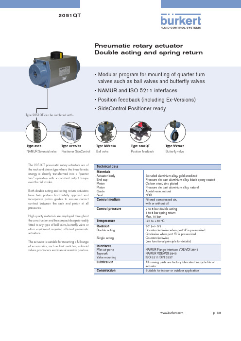
Pneumatic rotary actuatorDouble acting and spring return The 2051QT pneumatic rotary actuators are ofthe rack and pinion type where the linear kineticenergy is directly transformed into a “quarter turn” operation with a constant output torque over the full stroke.Both double acting and spring return actuators have twin pistons horizontally opposed and incorporate piston guides to ensure correct contact between the rack and pinion at all pressures.High quality materials are employed throughout the construction and the compact design is readily fitted to any type of ball valve, butterfly valve or other equipment requiring efficient pneumatic actuators.The actuator is suitable for mounting a full range of accessories, such as limit switches, solenoid valves, positioners and manual override gearbox.Extruded aluminium alloy, gold anodizedPressure die cast aluminium alloy, black epoxy coated Carbon steel, zinc platedType 6519NAMUR Solenoid valve Type 8792/93 Positioner SideControlType MV2650Ball valve Type 1062QTPosition feedbackType VV2670Butterfly valveFunctional principleDouble acting actuator (DA)Counter clockwise output operation is achieved by inserting pressure into Port ‘A’, to force piston apart thus rotating the actuator pinion counter clockwise. During the operation, air from the outer chambers is exhausted through Port ‘B’. Clockwise output operation is achieved by reverse of the above and inserting pressure into Port ‘B’.Single acting actuator (SR)Pressure applied to Port ‘A’ will cause the inner chambers to be pressurized, forcing the pistons outward to compress the springs. The pinion is rotated counter clockwise. Upon release of pressure through Port ‘A’ the springs will exert pressure to close the pistons and rotate the pinion clockwise rapidly. This action will often be used to close a 90oturn valve in shutdown mode.Pistons assembly variationsArrangement of springs for single acting actuatorActuator direction of rotation can be changed by switching both the pistons in accordance to the below diagramSprings can be added or removed according to torque requirement. It is recommended to install springs in accordance to the below diagramAir ConsumptionFree Air per stroke (Liters)Opening / Closing timeat 5.6 bar airWeight (kg)Torque Output (Nm) | Ordering Chart (other versions on request) Double acting actuator (DA)Torque Output (Nm) | Ordering Chart (other versions on request) Single acting actuator (SR)Dimensions [mm]AP01 to AP10 DA/ SR*** To be specified during order. Please refer to Ordering Chart.Parts listAP01 to AP10 DA/ SR* Suggested spare parts for routine maintenanceDimensions [mm]AP00 DAParts listAP00 DA* Suggested spare parts for routinemaintenanceDimensions [mm] - with accessoriesIn case of special application conditions,please consult for advice.We reserve the right to make technical changes without notice2051QT/EN/R1_12/2013With Type 6519 NAMUR solenoid valveWith declutchable manual override gearboxWith 879x positioner SideControlWith 1062QT position feedback。
flowserve limiterque mx系列电动执行器手册说明书

11
11 Absolute encoder
12 Cast aluminum housing
13 Declutch lever
14 Handwheel
10
Flowserve Corporation has established industry leadership in the design and manufacture of its products. When properly selected, this Flowserve product is designed to perform its intended function safely during its useful life. However, the purchaser or user of Flowserve products should be aware that Flowserve products might be used in numerous applications under a wide variety of industrial service conditions. Although Flowserve can (and often does) provide general guidelines, it cannot provide specific data and warnings for all possible applications. The purchaser/user must therefore assume the ultimate responsibility for the proper sizing and selection, installation, operation, and maintenance of Flowserve products. The purchaser/user should read and understand the Installation Operation Maintenance (IOM) instructions included with the product, and train its employees and contractors in the safe use of Flowserve products in connection with the specific application.
Spears 电动阀门电动驱动器选择手册说明书

Actuated Valves TechnicalElectric Actuator SelectionMade in the U.S.A.Suitable for Oil-Free air handling to 25 psi, not for distribution of compressed air or gasSee Spears ® Product Sourcebook for product offerings Page 6Revised: 12-20-2022Step 2: Actuator Code SelectionSpears ® actuated valves are available with either electric or pneumatic motors. Actuators are pre matched to each type and size of valve with proper operating torque and cycle time. Additional actuator accessories are selected and are factory installed on the Actuated Valve Package in Step 3 instructionsSelect the applicable options from either the Electric Actuators (Selection Table 4) or Pneumatic Actuators (Selection Table 5) and enter the designated Actuator Code portion of the package part number.Table 4: ELECTRIC ACTUATORS (Voltage-Enclosure Rating-Manual Override-Duty Cycle)ACTUATOR CODE Optional Control Number (not used on basic packages)1-2-3-4-56-7-8-910-11-12Reserved for Valve Reserved for SizeDuty Cycle (see note 3)1 = 25%2 = 75%3 = 100%4 = 50%5 = 70% (custom only)6 = 80% (custom only)7 = 40%8 = 60%9 = 20%Voltage (see note 1)A = 115 VAC 60 Hz B = 230 VAC 60 Hz C = 230 VAC 3-phase 50 Hz (EU)D = 230 VAC 3-phase 60 Hz E = 24 VAC F = 12 VDC G = 24 VDC L = 460 VAC 3-Phase 50 Hz (EU)M = 460 VAC 3-Phase 60 Hz N = 460 VAC 1-Phase 60 Hz R = 415 VAC 3-Phase 50 Hz S = 230 VAC 50 Hz (EU)T= 575 VAC 3-Phase 60Hz (EU)U = 115 VAC 50 Hz (EU)V = 208 VAC 3-Phase 60 Hz X = Single Indicator Switch Only (see note 2)Y = Double Indicator Switch Only (see note 2)Z = Actuator Bracket Only (see note 2)1 = 480 VAC 50 Hz2 = 480 VAC 60 Hz3 = 480 VAC 3-Phase 50 Hz4 = 480 VAC 3-Phase 60 Hz5 = 380 VAC 3-Phase 60 Hz6 = 12 VAC 60 Hz7 = 440 VAC 3-Phase 60 HzManual Override (see note 4)0 = None1 = Basic Manual Override2 = Declutchable Manual Override3 = Spring Return Open with Declutchable Manual Override (see not 5)4 = Spring Return Close with Declutchable Manual Override (see note 5)5 = Spring Return Open no override (see note 5)6 = Spring Return Close no override (see note 5)7 = RCE Battery Backup Actuator8 = Spring Return Open with Basic Manual Override (see note 5)9 = Spring Return Close with Basic Manual Override (see note 5)A = Super Capacitor Open with Basic Manual OverrideB = Super Capacitor Close with Basic Manual OverrideC = Super Capacitor Open with Declutchable Manual OverrideD = Super Capacitor Close with Declutchable Manual OverrideEnclosure1 = NEMA4 5 = NEMA 4 Double Powder Coated 9 = AWWA C=NEMA 6P,prolonged2 = NEMA4x 6 = NEMA 4x Double Powder Coated A = NEMA 7 Modulation enclosure submersion at a limited depth.(for 1/2"-2" modulated Ball /Butterfly)3 = NEMA 77 = NEMA 7 Double Powder Coated D=NEMA 84 = NEMA 98 = NEMA 9 Double Powder Coated B = NEMA 6Notes:1 - 460 VAC available on Butterfly Valves only.2 - Bracket & Indicator Switch Only part numbers do not allow any other options(must be Z000, Y000, or X000).3 - Standard Duty Cycles vary according to valve type and size as indicated in chart below. Standard Duty Cycles can be upgraded only.Note: 50% duty cycle available on non-standard, special order actuators only.Valve Type Size Range 25% Duty Cycle 75% Duty Cycle 100% Duty CycleBall Valve 1/2" - 2"XBall Valve 2-1/2" - 4"XButterfly Valve 1-1/2" - 10"XButterfly Valve 12" - 24"XDiaphragm Valve 1/2" - 8"X4 - Basic Manual Override is standard on Ball Valve sizes 1/2" - 3" with Declutchable Manual Override as an option.Declutchable Manual Override is standard on Ball Valve sizes 4" & larger and all Butterfly Valves.Standard Gate Valve and Diaphragm Valve packages have no override with Declutchable Manual Override as an option. Spring return notavailable on electric Diaphragm valves.5 - Electric Spring Return Actuators come standard with no type of override. Need to verify if either Declutchable Manual Override or BasicManual Overrides are available in all applications.。