ITQ电动执行器安装使用手册中文说明书
智能电动执行机构使用说明书
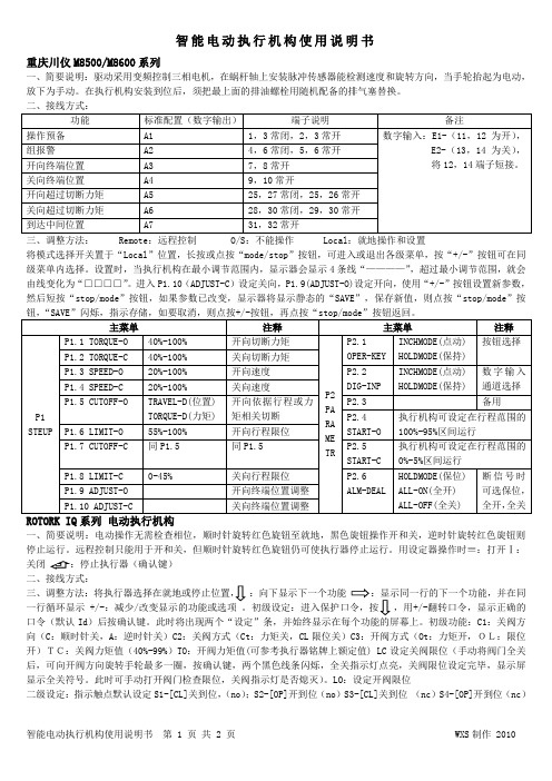
智能电动执行机构使用说明书重庆川仪M8500/M8600系列一、简要说明:驱动采用变频控制三相电机,在蜗杆轴上安装脉冲传感器能检测速度和旋转方向,当手轮抬起为电动,放下为手动。
在执行机构安装到位后,须把最上面的排油螺栓用随机配备的排气塞替换。
三、调整方法: Remote :远程控制 O/S :不能操作 Local :就地操作和设置将模式选择开关置于“Local ”位置,长按或点按“mode/stop ”按钮,可进入或退出各级菜单,按“+/-”按钮可在同级菜单内选择。
设置时,当执行机构在最小调节范围内,显示器会显示4条线“————”,超过最小调节范围,就会由线变化为“□□□□”。
进入P1.10(ADJUST-C )设定关向,P1.9(ADJUST-O)设定开向,使用“+/-”按钮设置新参数,然后短按“stop/mode ”按钮,如果参数已改变,显示器将显示静态的“SAVE ”,保存新值,则点按“stop/mode ”按钮,“SAVE ”闪烁,指示存储,如要取消,则点按+/-按钮,再点按“stop/mode ”按钮返回。
一、简要说明:电动操作无需检查相位,顺时针旋转红色旋钮至就地,黑色旋钮操作开和关,逆时针旋转红色旋钮则停止运行。
远程控制只能用于开和关,但顺时针旋转红色旋钮仍可使执行器停止运行。
用设定器操作时≡:打开Ⅰ:关闭 二、接线方式::向下显示下一个功能一行循环显示 +/-:减少/改变显示的功能或选项 。
初级设定:进入保护口令,按,用+/-翻转口令,显示正确的口令(默认Id )后按确认键。
此时将出现两个“设定”条,并始终显示在每个功能的屏幕上。
初级功能:C1:关阀方向(C :顺时针关,A :逆时针关)C2:关阀方式(Ct :力矩关,CL 限位关)C3:开阀方式(Ot :力矩开,OL:限位开)TC:关阀力矩值(40%-99%)TO :开阀力矩值(可参考执行器铭牌上额定值) LC 设定关阀限位(手动将阀门全关后,可向开阀方向旋转手轮最多一圈,按确认键,两个黑色线条闪烁,全关指示灯点亮,关阀限位设定完毕,显示屏显示全关符号。
直行程电动执行器使用说明书

ZDLQ/ZDLX 型电动三通合流/分流调节阀 主要用于将一股进口流体分成二股出口流体或 者把二股进口流体合成一股出口流体。三通阀分 为(ZDLQ)合流调节阀,(ZDLX)分流调节阀。 阀尺寸,压差较小时合流阀也可以作为分流阀 用,但阀尺寸大,压差高的场合请勿用分流阀。
标准技术参数
种 类 ZDLQ(合流三通调节阀)
361LSA-08/341LSA-08
3/4″、20
361LSA-20/341LSA-20
20~50
361LSB-30/341LSB-30
20~50
361LSB-50/341LSB-50
65~100
361LSC-65/341LSC-65
125~150
361LSC-99/341LSC-99
125~300
381LSC-99 381LSC-160 10000/16000
60 30/60
表 2 允许压差
公称通径 DN(mm) 25
2、死区范围调整 当灵敏度太高或太低时,调整电位器 W1 调整到输入信号缓慢减少或增大变化量不大于 0.1 mA 能使执行机构开始动作即可。 3、位置检测输出信号调整 A、将输入信号增大到 19 mA(或 9 mA)调整电位器 W4 使位置检测输出电流为 19 mA(或 9 mA), 经几次按上述方法检查和调整使位置检测信号和输入信号一一对应,两者差值应不大于 0.1mA。 B、满度位置检测调准确后,零位位置检测会自动跟踪,不需另行再作调整。 4、如果在反作用状态下运行,则只需将控制器上的红色微动开关 K3、K5 处于“OFF”,K4、 K6 处于“ON”,调整时重复上述步骤即可,此时输入信号为 4mA 或 0mA,输出轴处于最高位置; 输入信号为 20mA 或 10mA,输出轴处于最低位置。
ROTORK 执行器 E175C_IQT中文操作手册

电动执行机构请确保完整阅读和理解本手册Rotork设定器可按现场要求对执行器的控制、指示、保护功能进行设定。
所有的执行器在投入使用前请阅读本手册。
必须检查其设定符合控制系统的要求。
3.43.53.33124图3.7控制系统报警图标,图3.7是在远程控制系统保持一个有效的ESD或联锁信号(ESD,联锁功能或使用条件控制)实际存在时显示。
图3.6执行器报警图标,图3.8是在一个执行器报警实际存在时显示。
当报警存在时,电动操作将被禁止。
可能的原因是:・电机温度保护跳断・断电时电池电量过低*・电源故障・执行器控制系统报警*见电池报警(鉴别特殊的报警原因请参见帮助屏幕)。
电池报警图标,图3.9是在执行器检测到电池电量过低,完全没电或丢失时显示。
在电源接通时,执行器检测到电池没电,且执行器电源掉电禁止操作功能[OS]有效(参见第58页)时,电池报警和执行器报警图标(图3.8和3.9)都将显示,电动操作将被禁止。
图3.9图3.8246357执行器的设定功能可以用口令进行保护默认口令,设定方式口令改[IE]注:新口令将在下次进入设定 方式时有效。
口令显示,检查方式在进入所需要的方式后按 键将显示程序分支符号。
(请参阅第14页第7.7节)按 键 进入初级设定功能。
(请参阅第15页第8节初级设定功能)按 键进入二级设定功能。
(请参阅第25页第9节二级功能设定)典型的执行器功能显示-设定方式现场显示为顺时针关现场显示为逆时针关闭。
现场显示为力矩关-默认现场显示为限位关选择所需要的方式后,按 键。
所选项闪烁,说明被设定。
按 键。
现场显示为力矩开-默认现场显示为限位开按 键。
所选项闪烁,说明设定。
按 键。
额定值的40%额定值的99%额定值40% 99%额定值加强加矩在检查方式下,查看完开阀力矩后,按键,显示将返回阀位指示状态。
关闭限位手动将阀门转至全关,可向开阀方向旋转手轮最多两圈。
按 键。
两个黑色线条闪烁,全关指示灯点亮,说明关闭限位已被设定。
ITQ系列电动转角阀门安装和操作手册说明书

Installation and operating manual(ITQ-0100, 0160, 0240, 0350, 0500, 08001100, 1500, 2000 & 3000) 3F, 371-36, Gasan-Dong, Geumchun-gu, Seoul, Korea Tel : 82-2-855-1365, 66 Fax : 82-2-855-1367 E-mail : ***************.krITQ series Electric quarter turn actuatorContents1. Before operating actuator (3)2. About ITQ actuators (4)1)Internal & external component 3) Specification5) Mounting Base (ISO5211) 2) Internal component4) Features & Structure6) Removable drive bushing5,67,893. Sizing and Application (10)4. Setting (11)1)Manual operation 3) Torque switches 5)Indicator 2) Limit switches4)Stopper bolts 125. Location of actuator on the pipeline (13)1) Location of actuator on the pipeline2) Orientation of actuator6. Electrical wiring (14)1) Before wiring3) Checking the rotating direction ofactuator 2) Electrical wiring4) Commissioning(Electrical)7. Others (15)1) Jamming2) Special tools for setting8. Caution9. After sales service ………. ……….15161) Free of charge 2) User’s charge3) Trouble shootings10. Maintenance (17)1) Lubrication 3) Maintenance2) Regular operation 4) OthersITQ series Electric quarter turn actuatorITQ series Electric quarter turn actuatori.About ITQ actuator1)External componentsITQ0100 ~ ITQ1100ITQ series Electric quarter turn actuator2) Internal componentITQ0160 ~ ITQ1100ITQ1500 ~ ITQ3000CAPACITOR TERMINAL BLOCKASSEMBLYMOTORTORQUE SWITCH ASSEMBLYLIMIT SWITCH ASSEMBLYPOTENTIOMETER ASSEMBLYCAPACIT TERMINAL BLOCK ASSEMBLYMOTORITQ series Electric quarter turn actuator3)Specification(On-Off)Enclosure Weather proof enclosure IP67, NEMA 4 AND 4X, O-RING SealedMain power supply 110/220V AC 1Ph, 380/440V AC 3Ph 50/60Hz, ±10%Control power supply 110/220V AC 1Ph 50/60Hz, ±10%Duty cycle(On-Off) S2, 20~50% Max 30MinDuty cycle(Modulating) S4, 30~50%, 300~1200starts/hourMotor Squirrel caged induction motorLimit switches OPEN/CLOSE, SPDT, 250V AC 10A RA TINGTorque switches OPEN/CLOSE, SPDT, 250V AC 10A Rating(Except for ITQ0100)Stall protection(Temp.) Built in thermal protection, OPEN 150℃±5℃/CLOSE 97℃±15℃Travel angle 90˚±5˚(0˚~100˚)Position indicator Plate with indication arrowManual override De-clutchableSelf locking Provided by double worm gearing(No brake)Mechanical stopper 1 each for each travel end(OPEN and CLOSE), external adjustableHeater 5W (110/220V AC) Anti-condensationCable entries 2- PF3/4” TAPLubrication EP Type greaseTerminal block Screw and lever push type(Spring loaded)Ambient temperature -20℃~+70℃(Except for optional electronic board)Ambient humidity 90%RH Max, (Non-condensate)Dielectric strength 1500V AC 1minuteInsulation resistance 500V DC 30M OhmAnti-vibration X Y Z 10g, 0.2~34Hz, 30minuteExternal coating Dry powder (Polyester)4)Features and structure(1) General :ITQ series actuator is designed for the 90 degree turn application such as damper, ball, plug, butterfly valve and other equipment(2) Wide range of torqueMin. 100Nm to Max 3000Nm. In between there are 12 models and cater for various torque depending on application.(3) MaterialMaterial is hard-anodized AL alloy and external coating of epoxy powder is suitable for the severe condition especially against the corrosion. Housing is designed in accordance with standard of ex-proof and IP67.ITQ series Electric quarter turn actuator(16) AdaptionMounting base is designed according to ISO5211 but different dimension depending on application is also possible. Removable drive bushing provides convenient machining for adaption.(17) LubricationUsing EP type Grease Moly, no need to refill lubricant for the long time.(18) OthersITQ guaranty high performance, high quality product throughout various and severe test and inspection.5) Mounting base according to ISO5211 standardITQ1500,ITQ2000 & ITQ3000ITQ0350, ITQ0500 ITQ0800, ITQ1100Removable Drive bushings for adaptionITQ0100 ITQ0160, 0240 ITQ0350, 0500 ITQ0800, ITQ1100 ITQ1500, ITQ2000 & ITQ3000ITQ0100 ITQ0160, ITQ0240ITQ series Electric quarter turn actuator3. Sizing and applicationNote :1. Above table just show reference and no guaranty!2. Sizing should be done after careful reviewing valve factory, temperature, characteristics of fluid and etc.3. Having application under special condition such as high and low temperature, seawater, severe corrosion, high vibration), please consult with our technical dept before selecting actuator.4. Decision by user ignoring our recommendation, we have right to avoid any responsibility.ITQ series Electric quarter turn actuator3)Torque switchesTorque Switches are set by factory before delivery and therefore no need to set the switches again, but just do as follows for check if switches functions well.①Push the lever of close switches by screw driver until it sounds “click” then actuator should stopimmediately. If it stops, switches work well.②Check open switches as per just same with above.③No guaranty in performance once these switches are set again.④Before setting, if it is really necessary to adjust, please consult with factory.ITQ series Electric quarter turn actuator4)Stopper bolt setting①Before manual operation, get both nuts loose which are engaged with stopper bolts and turn stopper bolt tocome out by 3~ 4 threads.②Move actuator full close position by manual.Once cam hit the lever of limit switch to trip, stop manual operation.③Then turn close stopper bolt to go forward until it don’t’ not go further (End of stopper bolt contacts the 2ndworm wheel).④Turn close stopper bolt to come out by 2 threads and tighten the loosen nut.⑤Do as per same with above for open stopper bolt5)Indicator setting①Move actuator full close position and turn indicator by hand until orientation of indicator is aligned to thefigure of window.②Tighten the bolt (Be careful not to be injured by the cutting edge of indicator and leakage of electricity whenpower is on)③Figure of Window and indicator according to AWWA standardITQ0100ITQ0160~ITQ1100ITQ1500~ITQ3000ITQ series Electric quarter turn actuator5. Recommendation for installation of actuator in the pipeline1)Location of actuator on the pipeline2) Orientation of installation of actuator① No restriction, but it is recommended to install actuator in the position which cable entry face the groundorientation for watertight function and hand wheel faces front for easy manual operation without interruption. ② Reserve the space for maintenance.ITQ series Electric quarter turn actuator6. Electrical wiring1) Before wring①Cable entries are machined with PF3/4” tap and sealed by Plug before delivery.②Please remain the plug as it is if user doesn’t use both cable entries.③Please make sure to seal the entries by using rubber or metallic packing after wiring, so that water may notcome in.④When user use actuator as ex-proof, please make sure to use the certified connection component which is atleast same grade with actuator.⑤This is not our scope of supply, but if user don’t use suitable component, factory won’t guaranty theperformance of ex-proof actuator.2) Electrical wiring①Check if electrical specification like as power, wiring & etc are correct or not.②One sheet of wiring diagram is to be supplied together with actuator.③Do the wiring as per the given wiring diagram, such as power, control power , internal wiring and ground.④Make sure to supply electric power to heater for keeping inside of actuator clean and dry.⑤Make sure to check wiring to the terminal is strong enough.⑥Make sure that one relay operates one actuator only( Can not operate two or more actuators simultaneously)⑦Make sure to clean inside of actuator and no foreign material inside.3) Check rotating direction①In 3 phase actuator, operator should check the rotating direction of actuator before electrical operation.②If operating direction is wrong, limit switches doesn’t function and it results damage from jamming ormotor’s overheating.③So, put the actuator at 50% open(or Close) position by manual and supply power into the actuator andcheck it’s rotating direction.④If actuator moves open as per open signal, the direction it is O.K, but reverse, need to change the wiring.⑤Among 3 of power wires, change 2 wires each other.⑥Then check the rotating direction again in order to confirm it again.4)Commissioning①Make sure to check the rotating direction of actuator first before operation.②Check the function of limit and torque switches, direction of indicator and space heater.③Check lever movement is O.K (Manual override)④Check the lamps in the control panel.⑤After commission, please make sure to tighten the 4 bolts of the top cover and to do proper sealing.ITQ series Electric quarter turn actuator7.Others1) Jamming①In case that actuator moves wrong direction and moves over the travel limit, internal worm gear contacts thestopper bolt and engaged each other. This is so call jamming and can not move actuator at all.②How to solve-Off the power-If jamming is happened during close, take close stopper bolt to come out by about 2 ~3 threads-Pull over the lever and put it manual position.-Turn hand wheel to counterclockwise until 50% open position.-Check rotating direction again.-If everything is O.K, put stopper bolt original position.-If jamming is happened during open, procedure is same with close, but turn hand wheel to clockwise by manual.2) Special tools for setting①L-Wrench 1 set(Metric)②Screw drivers (--, +)③Spanner set (Metric), Monkey spanner 200mm, 300mm 1 each,④Wire stripper, Long nose, Light⑤Multi Meter (AC, DC V olt, Resistance)⑥DC signal generator (0~4mA DC) : RPC option⑦mA DC Meter (0~25mA DC) : RPC and CT8.Caution①Selection of valve and actuator : Review all specification of valve and actuator carefully before makingselection and reserve about 30% torque of actuator for safety purpose. If required torque is 90Kg-m, recommended actuator torque is about 117Kg-m.②Option : Please consult with factory before making selection, if possible.③Before necessary setting such as limit switch, please don’t operate actuator either fully open or fully close.④After electrical wiring, make sure to secure the sealing of cable entries.⑤Before operating actuator, please review this manual carefully and follow the instruction without fail.Please be careful at temperature, humidity, vibration, voltage drop.⑥Storage : Keep actuator dry, clean and cool.⑦Trouble : Please refer to following trouble shooting but please don’t dismantle the actuator withoutconsulting with factory.⑧If repair or maintenance is required, please check the model, electrical condition, serial Number and currentsituation to inform factory.ITQ series Electric quarter turn actuator10. Maintenance1)LubricationLubrication is already done by factory and generally no need to refill it again.But in the places such as very dry condition below R.H 15% or high temperature higher than 30o C, it is required to do lubrication once two year through Grease Nipple.2)Regular operationElectrical power always should be supplied to actuator and it is recommended to operate actuator once a week.3)MaintenanceIn order to use actuator for long time, regular maintenance once a year is required.Pleas check operating condition, corrosion, painting & etc.4)OthersShould you have any further queries, please contact us through Phone, fax and E-mail without hesitation.。
电动执行器操作手册
rotork IQ系列 电动执行机构 安装及维护手册

当Rotork工作人员或指定代理商按照合同规定进行现场调试和验收 时,执行器组态的相关文件应让用户留档备查。
Rotork 增强型设定器
Rotork 设定器
本手册提供如下指导: * 手动和电动(就地和远程)操作。 * 执行器的准备和安装。 * 为了正确操作阀门,需要对执行器进行基本设定。 * 根据现场具体控制和指示的要求,对执行器进行组态
限位。 · Moving Open - 执行器正在向开阀方
向运行。 · Moving Closed - 执行器正在向关阀方
向运行。 ·Stopped - 执行器在行程中间停止运
行,上面可显示具体百分比开度。
· Timer Active - 只有在备选的间断计 时器开启时显示。设定间断计时器 的关闭时间,可以使执行器在行程 中间以相等的周期间断停止运行。 请参见第59页9.13节。
Closed Limit
图 3.5 在动力电源断开时,电池可以支持屏 幕显示和连续的阀位变化。但无论如 何,电池不支持屏幕的背景照明、阀 位指示灯或点阵文字显示。
发光二极管指示灯 警告:行程中间时的颜色会受
到观看角度和亮度的影响。 阀门全关时发光二极管的颜色可根据 需要改为红色。行程中间时发光二极 管可根据需要不发光。 (请参见第62页第9.16节。 )
4 准备驱动轴套
4.1 IQ10 - IQ35 A、Z型推力底座 4.2 IQ10 - IQ35 B型非推力底座 4.3 IQ40 - IQ95 A、Z型推力底座 4.4 IQ40 - IQ95 B型非推力底座
5 安装执行器
5.1 提升杆阀门 - 顶装 5.2 带齿轮箱的阀门 - 侧装 5.3 非提升杆阀门 - 顶装 5.4 手轮密封
瑞基RQ说明书
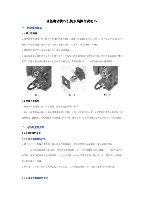
瑞基电动执行机构安装操作说明书一、驱动套的加工1.1 推力型基座1)将电动装置倒向一侧,卸下两个固定基座的螺钉,将带有轴承组件的驱动套卸下。
取下驱动套二端的推力轴承(靠近驱动套中部凸肩的二个推力轴承环可以不取下)。
(如图1-1,图1-2)2)根据阀杆螺纹尺寸在驱动套上加工相应的内螺纹。
3)清洗好加工好的驱动套及拆下的其它部件,按照与上述步骤相反的步骤将驱动套、基座同电动装置主体装配好,装配时要注意将输出轴上的驱动爪与驱动套上表面的槽对正。
(轴承组件必须加满润滑脂)1.2 非推力型基座1)将电动装置倒向一侧,拆下基座,露出驱动套顶端的卡环。
2)转动卡环槽至输出轴上的驱动爪处或用螺丝刀挑出卡环,即可卸下驱动套。
按所配阀门的联接形式加工驱动套轴孔、键槽或结合爪后装回电动装置,卡上卡环,装好基座,装基座前要在基座与驱动套间抹些润滑脂。
二、电动装置的安装2.1与明杆阀的安装2.1.1 推力型基座的安装a.对于出厂时已按客户要求加工好驱动套内的螺纹时,将电动装置和驱动套作为整体同阀门装配。
先将电动装置挂上手动档,将电动装置放在阀门上,驱动套螺纹孔对正阀杆,向打开方向转动手轮,使驱动套螺纹套进阀杆螺纹,继续转动手轮,使电动装置紧紧贴在阀门法兰上,然后再转动两圈,装上固定螺栓,旋紧。
b.对于客户自行加工驱动套内螺孔时,先按上述1.1加工装配好驱动套,再按上述a同样步骤装配。
2.1.2 非推力型基座的安装非推力型驱动套加工完毕装回电动装置后,即可随电动装置整体与阀门装配。
先将电动装置挂上手动档,将电动装置放在阀门上使阀杆伸入驱动套孔或使驱动套上的结合爪与阀上的结合爪相啮合,向打开方向转动手轮,使电动装置紧贴在阀门法兰上,然后再转动两圈,装上固定螺栓,旋紧。
2.2与带齿轮箱的阀门安装先检查一下驱动套、阀门齿轮箱输入轴、键、键槽的配合是否合适,将基座、驱动套先与电动装置装配好,然后把电动装置往齿轮箱的法兰上放,使齿轮箱输入轴伸入驱动套轴孔,转动电动装置手轮,使键槽与键对正,键落入驱动套的键槽,然后上紧安装螺栓。
NQ-I安装使用调试说明书2012
7.1接线端子序号说明 7.2NDQ/NJQ智能型电动执行器电气原理图 7.3NDQ/NJQ智能型电动执行器控制接线图 7.3.1NDQ/NJQ智能电动执行器远方开关量(手动)控制 7.3.2ESD控制 7.3.3远方模拟量(自动)控制(可选功能) 7.3.4R1-R4状态反馈 7.3.5报警信息反馈 7.3.6远方位置反馈 7.3.7状态反馈(可选功能)
2.2 转矩型基座
1、将执行器倒向一侧,拆下法兰基座,将驱动螺母取出。 2、按所配阀门的联接形式加工驱动螺母轴孔、键槽或牙嵌后装回执行器,装法兰基座前要在基座与驱动
螺母间抹些润滑脂。 3、旋紧法兰基座底部的圆螺母,然后再松开1/4~1/2圈,然后安装两个骑缝螺钉,即:在圆螺母和法兰
基座连接的螺纹处加工2个M5深8的螺纹孔(均布),安装两个M5×8的紧定螺钉。
☆返回键:方式钮从“停止” 位置—>“远方” 位置, 以下简称按下返回键;
5.1.3操作钮代表的按键
☆下移键:操作钮—>“关闭” 位置,以下简称按下下移键; ☆加 键:操作钮—>“打开” 位置,以下简称按下加键;
5.2液晶显示
该执行器上配有一点阵图行式液晶显示屏。其布局有Ⅰ区、Ⅱ区、Ⅲ区。
Ⅲ区
Ⅰ区为阀位显示区,以阀位开度百分比的形式实时显示当前阀位值;
3.2与带齿轮箱/蜗轮箱的阀门安装
先检查一下驱动螺母、齿轮箱/蜗轮箱输入轴、键、键槽的配合是否合适,将法兰基座、驱动螺母先 与执行器装配好,然后把执行器往齿轮箱/蜗轮箱的法兰上放,使齿轮箱/蜗轮箱输入轴伸入驱动套轴 孔,转动执行器手轮,使键槽与键对正,键落入驱动螺母的键槽,然后上紧安装螺栓。
3.3与暗杆阀门安装
3、执行器的安装 3.1与明杆阀的安装
- 1、下载文档前请自行甄别文档内容的完整性,平台不提供额外的编辑、内容补充、找答案等附加服务。
- 2、"仅部分预览"的文档,不可在线预览部分如存在完整性等问题,可反馈申请退款(可完整预览的文档不适用该条件!)。
- 3、如文档侵犯您的权益,请联系客服反馈,我们会尽快为您处理(人工客服工作时间:9:00-18:30)。
ITQ电动执行器安装使用手册
(ITQ-0100, 0160, 0240, 0350, 0500, 0800 1100, 1500, 2000 & 3000)
目录
2.ITQ 执行器
1)外部部件
ITQ0100 ~ ITQ1100
2) 内部部件
ITQ0160 ~ ITQ1100
ITQ1500 ~ ITQ3000
CAPACITOR
TERMINAL BLOCK ASSEMBLY
MOTOR
TORQUE SWITCH ASSEMBLY
LIMIT SWITCH ASSEMBLY
POTENTIOMETER ASSEMBLY
CAPACIT TERMINAL BLOCK ASSEMBLY
MOTOR
(17) 润滑
使用Moly EP型润滑油,长时间不必再加油。
(18) 其它
ITQ通过各种严格的检测,保证高性能、高质量。
5)ISO5211 标准的安装基座
ITQ0100 ITQ0160, ITQ0240
ITQ1500, ITQ2000 & ITQ3000
ITQ0350, ITQ0500 ITQ0800, ITQ1100
连接用可拆卸式驱动轴瓦
ITQ0100 ITQ0160, 0240 ITQ0350, 0500 ITQ0800,ITQ1100 ITQ1500, ITQ2000 & ITQ3000
3. 选型与应用
VALVE ACTUATOR
BUTTERFLY
VALVE 10K
(ANSI 150#)
BUTTERFLY
VALVE 20K
(ANSI 300#))
2-WAY BALL
VALVE 10K
(ANSI 150#)
2-WAY BALL
VALVE 20K
(ANSI 300#)
3-WAY BALL
VALVE 10K
(ANSI 150#)
ITQ-0100100A80A50A40A40A ITQ-0160125A100A65/80A50A50A ITQ-0240150A125A65/80A65/80A ITQ-0350200A150A100A
ITQ-0500300A150A
ITQ-0800350A250A125A125A ITQ-1100400A300A200A150A150A ITQ-1500450A350A
ITQ-2000500A400A250A200A200A ITQ-3000600A450/500A300/350A250/300A250/300A 注 : 1. 上表仅供参考,不承担任何责任!
2. 应详细咨询阀门厂温度、流体特性等后再选型。
3. 特殊条件如高温、低温、海水、恶劣腐蚀性条件、高振动下的应用,在选定执行器前请咨询我们技术部门。
4. 对用户无视我们的劝告所做的决定,我们有权力回避任何责任。
4)止动螺栓设定
①在手动操作前,松开止动螺栓的两个螺母,把止动螺栓拧出3~4个螺纹。
②手动使执行器运行到全关位置。
一旦凸轮碰到限位开关的杆,停止手动运行。
③向前转动关闭止动螺栓,直到不能再往前。
(止动螺栓的末端碰到2级蜗轮)
④把关闭止动螺栓拧出2个螺纹,拧紧松开的螺母。
⑤打开止动螺栓也如上办理。
5)指示器设定
①使执行器运行到全关位置,用手转动指示器直到指示器的方向对准视窗的数字。
②拧紧螺栓(小心不要被指示器的切边碰伤或通电时漏电)。
③视窗的数字与指示器符合AWWA标准。
ITQ0100 ITQ0160~ITQ1100
ITQ1500~ITQ3000
5.执行器在管道上的推荐安装
1)执行器在管道上的位置
2) 执行器安装的方向
1)无限制,但是推荐执行器安装时,使电缆接口朝向地面方向,以保证防水功能,使手轮在正面,以
方便无中断地手动运行。
2)留出维护空间。
10. 维修保养
1)润滑
因为工厂已经充分供应了润滑油,正常运行中一般不必再注入润滑油。
不过,在湿度为15%以下的很干燥的使用场合和30度以上的高温地区使用时,
需要约2年1次通过润滑油嘴注入润滑油。
2)定期运行
最好一直供电,约1周1次定期试运行。
3)维修保养
为了执行器的长时间正常使用,要求约一年一次定期检查及保养。
检查动作状态、腐蚀、涂层等。
4)其它
如有任何其它问题,请随时电话、传真、E-MAIL联系我们。
(注:文档可能无法思考全面,请浏览后下载,供参考。
可复制、编制,期待你的好评与关注!)。