商用汽车排气后处理系统的技术和策略
重卡用国V发动机排气后处理系统设计

Ke r s He v u ytu k Ch n e sin Afe-r ame t ywo d : a yd t c ; ia r V mis ; trte t n o CL No: 6 .3 Do u n o e A Aril C . U4 42 4 c me t d : c tceI 1 7 .9 8 ( 0 2 0 . 70 D: 6 17 8 2 1 ) 7 1.5
PM . 1 0
8
P: 4 Mn1
E A 0 P20
Ox 3 : 5
NO :A x3 O
PM: 4 nl
周2
P O1 M: 5 / 0 5 ,20 /
' 0 欧 I 2 6 0 V
20 07
P n ∞ M
NO :. x20
P 0o 7 M: 2
闲3
P t 1 M|.0 1
N x转 化率可 达 8% O 5 以上 , 种后 处理 技术 方案 的作 两
NO 1 x 0,
2】 (3 l
NO : 7 xO2 O= r35
J20 P0 9
P M曲. 01
用机 理 见图 2 。
N 由4 Ox 2 1 欧 Ⅵ 04 以后
用 的是过 量空气 燃烧 和 高压缩 比技 术 ,c O和 c H排 排放 要 求 的 ,比如 欧Ⅵ 排放 , 需要对 不 同后 处理 技 放 比汽 油机 低得 多,由于 N x和 P 人体健 康伤 害 术进 行组 合才 能实 现 。 O M对
极大 ,因此 柴油 机排放 控 制主要 控 制 N x和 P ,柴 0 M
前 言
汽车排气系统工作原理与维修

汽车排气系统工作原理与维修汽车排气系统是汽车发动机最重要的组成部分之一,它承担着排放废气和控制噪音的重要任务。
本文将介绍汽车排气系统的工作原理以及常见的维修方法。
一、工作原理汽车排气系统的主要组成部分包括排气歧管、催化转化器、消声器和尾管。
这些部件协同工作,完成排放废气和减少噪音的任务。
1. 排气歧管排气歧管位于发动机缸体之下,负责将每个汽缸的废气收集到一起,并将其导向催化转化器。
排气歧管设计合理与否直接影响到发动机的性能和燃烧效率。
2. 催化转化器催化转化器是汽车排气系统中的一个重要设备,通过催化剂将有害气体转化为无害物质。
其中,氧化还原催化剂将一氧化碳(CO)和不完全燃烧的碳氢化合物(HC)氧化为二氧化碳(CO2)和水蒸气(H2O),而氮氧化物(NOx)催化剂则将NOx分解为氮气(N2)和氧气(O2)。
3. 消声器消声器主要用于减少发动机排气过程中产生的噪音。
它通过使用吸声材料和反射器等降低噪音的传播和反射,将噪音尽可能地减少到合理范围内。
4. 尾管尾管是排气系统的最后一个组成部分,将处理过的废气排出汽车。
在一些高性能汽车中,尾管还可以通过调整形状和材料来改善排气流动性能,提高发动机的输出功率。
二、维修方法汽车排气系统在长期使用中可能会出现一些故障,如排气歧管老化、催化转化器堵塞等。
下面列举一些常见的维修方法:1. 检查和清洁定期检查排气系统的各个部件,确保其没有损坏和堵塞。
若发现有异常,并及时进行清洁和修复。
例如,清理催化转化器表面的碳积和杂质,以确保其正常工作。
2. 更换零件如果排气系统的某个组件损坏无法修复,就需要考虑更换零件。
例如,排气歧管出现裂纹时需要更换新的排气歧管,以免废气泄漏影响发动机性能。
3. 消声器的维护消声器是排气系统中易损件之一,需要特别维护。
定期检查消声器是否出现裂纹和松动,及时更换。
同时,注意避免在不良路况下碰撞消声器,以防损坏。
4. 防腐蚀处理由于排气系统暴露在恶劣的工作环境下,易受到腐蚀。
商用车SCR尾气后处理系统的匹配控制技术
设计 ・ 计算 ・ 研究 ・
商用车ห้องสมุดไป่ตู้S R尾气后 处理系统 的匹配控 制技 术 C
杨 宝萍 王 宗社 朱 涛利
( 西重型汽车有 限公司 ) 陕
摘
要:借鉴国外排放控制的成功经验 ,S R尾气后处理控制技术 已成 为各 厂家的首选 方案 。本 文就 S R尾气 C C
后 处 理 控 制 技 术 的工 作 原 理 、基 本 组 成 、工 作 过程 及 整 车 集 成 与 匹 配 设 计 等 方 面做 了 系 统 的 介 绍 和 分 析 ,期 望 能 帮 助 读 者 对 该 控 制 技 术 有 一个 全 面 的 认 识 ,并 对 今 后 的产 品开 发 工作 有所 裨 益 。
排 放法 规 的实 施 日期 已不 再遥 远 。 了应对 新 的排 单 元给 出 的指 令 精 确 地 将 与 发 动机 运 行 工况 相 匹 为
放法 规要 求 ,各 发动机 、主车 生产 厂 均加 快 了新一 配 的尿 素量 喷入 排气 管 , 素 分解 出的氨与 氮氧 化 尿 代车 型 的研 制 开发 步伐 。
c n o e h o o y h sb c me t e p e e r d p o r m. e p p ri to u e d a a y e e b sc c mp st n t e o t l c n l g a e o r f re r g a Th a e n r d c sa n lz st a i o o i o , h r t h n h i wo k n r c s n e il n e r t n a d ma c f h CR y t m. o k f r r ep t e r a e n e s n r i g p o e sa d v h ce i t g a i n t h o e S o t s se L o wad t h l e d rt u d r t d o o h o a
汽车废气排放控制的最佳方法

汽车废气排放控制的最佳方法控制汽车污染物排放的技术可以分为两类:降低污染物生成量的技术,又称为机内净化技术;净化或处理发动机排出后污染物的技术,又称为机外净化技术。
随着发动机技术的进步和发展,目前车辆排放控制的机内、机外净化技术都达到了比较完善的地步。
现代汽油发动机排放控制较为成熟的技术主要有以下几个方面:发动机结构优化技术,如采用多气阀进气机构、组织进气气流、对燃烧室加以改进等。
通过改善发动机燃烧状况,提高燃烧效率,降低发动机一氧化碳、碳氢化合物的生成量。
闭环电控发动机管理技术是一种精确控制发动机供油过程和点火过程的技术,能根据反馈控制使发动机始终工作在最佳状态。
一方面可以有效降低发动机一氧化碳、碳氢化合物的生成量;另一方面为加装三效催化转化器提供空燃比条件。
燃油蒸发污染物控制技术是一种对油箱和供油系统排出汽油蒸气污染物进行控制的技术,在国外是从20世纪80年代就较为普遍使用的技术。
可控制汽油车20%左右的碳氢化合物排放。
闭式曲轴箱通风技术是一种控制发动机曲轴箱窜气造成环境污染的技术。
这一技术国内若干年前就已普遍使用,可控制汽油车20%左右的碳氢化合物排放。
废气再循环技术是一种将发动机排气引入到进气中,通过降低发动机气缸内氧气的相对含量和最高燃烧温度,来减少氮氧化物生成量的技术。
可降低40~60%的氮氧化物生成量。
三效催化转化器技术是一种利用氧化和还原反应,将汽车排气中的一氧化碳、碳氢化合物、氮氧化物同时转化成无害的二氧化碳、氮气、水的技术。
在一定条件下,对污染物的转化效率可达80%以上,是目前最为有效的汽油车机外净化技术。
但是,为保证其工作效能,需要发动机具备闭环电控系统,并燃用无铅汽油。
改进油料。
燃油的质量、组分、添加剂对排放均有一定影响。
因此,改进油料的质量和组分,是进一步降低车辆污染物排放的有效方法。
解放j6后处理的原理
解放j6后处理的原理
解放J6柴油车排气后处理系统的工作原理可以概括为:
一、催化转化器
装有铂钯饼状催化剂,将排气中的一氧化碳、碳氢化合物氧化为二氧化碳和水。
二、DPF 颗粒捕获
安装了微孔陶瓷过滤器,可以捕集细小悬浮颗粒,防止排放到空气中。
三、发动机控制
通过电子控制系统优化喷射策略、进气量等参数,减少生成悬浮颗粒。
四、EGR 内循环
回收部分废气再进入气缸内燃烧,降低燃烧温度,减少氮氧化物生成。
五、DOC 氧化
安装氧化催化器(DOC),将一氧化碳、碳氢化合物氧化为二氧化碳和水。
六、DPF 再生
当颗粒堆积到一定程度,通过燃烧烘烤的方式重新打开过滤器孔道。
七、SCR 选择性催化还原
在排气中注入尿素溶液,利用催化反应将氮氧化物转化为氮气和水。
八、ASC 氨逃逸催化
降解未充分反应的尿素,防止二次污染。
通过多级协同处理,大幅降低颗粒物、氮氧化物的排放,使废气达到排放标准,实现清洁排放。
汽车发动机排气处理系统优化设计

汽车发动机排气处理系统优化设计近年来,随着环保意识的提升和环境污染程度的加剧,汽车排气处理系统的优化设计已成为汽车制造商和工程师们的重要课题。
汽车发动机排气处理系统包括废气净化装置和尾气处理装置,其优化设计可以有效减少尾气排放和提升发动机性能。
本文将探讨汽车发动机排气处理系统优化设计的几个关键点。
首先,废气净化装置是汽车发动机排气处理系统的核心组成部分。
它的优化设计主要包括两个方面:一是减少排放物的生成,二是提高排放物的净化效率。
为了实现这个目标,可以采用的技术手段包括废气再循环、催化剂和颗粒捕集过滤器等。
废气再循环技术通过将部分废气重新引入燃烧室,降低燃烧温度,减少氮氧化物的生成。
催化剂则通过化学反应将有害物质转化为无害物质,例如将一氧化碳转化为二氧化碳。
同时,颗粒捕集过滤器可以有效捕集柴油发动机产生的颗粒物,减少其对环境的污染。
其次,尾气处理装置的优化设计也是非常重要的。
尾气处理装置主要包括催化转化器和颗粒捕集过滤器等。
催化转化器通过化学反应将有害气体转化为无害气体,例如将一氧化碳和氮氧化物转化为二氧化碳和氮气。
而颗粒捕集过滤器可以捕集尾气中的固体颗粒物,减少其对空气质量的负面影响。
为了实现尾气处理装置的优化设计,可以采用新型材料和结构设计。
例如,使用高活性的催化剂,增加催化反应的效率;采用多通道的颗粒捕集过滤器,提高颗粒物的捕集效率。
此外,优化发动机的工作循环参数也是汽车发动机排气处理系统优化设计的重要方面。
通过调整燃烧室的进气、压缩、燃烧和排气过程,可以减少有害排放物的生成和提高发动机的燃烧效率。
例如,采用直喷技术可以实现燃油的精确喷射和混合气的均匀分布,减少氮氧化物的生成。
此外,排气压力和排气温度的控制也是非常重要的,可以通过增加涡轮增压器的效率和优化冷却系统来实现。
最后,新能源汽车的兴起也对发动机排气处理系统的优化设计提出了新要求。
新能源汽车的排气处理系统主要是针对电动车辆和燃料电池车辆而言。
汽车发动机的排气系统优化方法
汽车发动机的排气系统优化方法汽车发动机的排气系统对于车辆的性能、燃油经济性和环保表现都有着至关重要的影响。
一个优化良好的排气系统不仅能够提升发动机的功率输出,还能降低尾气排放,使车辆更加节能环保。
在这篇文章中,我们将探讨一些汽车发动机排气系统的优化方法。
首先,我们来了解一下排气系统的基本组成部分。
排气系统通常包括排气歧管、排气管、催化转化器、消声器等组件。
排气歧管负责收集各个气缸排出的废气,并将其引导至排气管;排气管将废气输送至后续的处理装置;催化转化器用于净化废气中的有害物质;消声器则主要起到降低排气噪声的作用。
要优化排气系统,一个关键的方面是改进排气歧管的设计。
排气歧管的形状和长度会影响废气的流动速度和压力。
合理设计的排气歧管能够减少排气阻力,提高废气排放的顺畅性。
例如,采用等长排气歧管可以使各气缸的排气脉冲更加均匀,从而提高发动机的充气效率和动力性能。
此外,通过优化歧管的管径和弯曲程度,也能降低气流的摩擦损失。
排气管的直径和材质选择也是优化的重要环节。
较大直径的排气管可以降低排气背压,但过大的管径可能会导致低速时扭矩的损失。
因此,需要根据发动机的特性和使用场景来选择合适的管径。
在材质方面,不锈钢等高性能材料具有良好的耐腐蚀性和导热性,能够提高排气系统的使用寿命和性能。
催化转化器的优化对于尾气净化效果至关重要。
新型的催化转化器技术能够更高效地将有害气体转化为无害物质。
例如,采用更先进的催化剂配方和增加催化涂层的表面积,可以提高转化效率。
同时,优化催化转化器的安装位置和气流分布,有助于确保废气与催化剂充分接触,提高净化效果。
消声器的设计既要考虑降噪效果,又要尽量减少对排气性能的影响。
通过采用复杂的内部结构和吸音材料,可以有效地降低排气噪声。
然而,过度的消声处理可能会增加排气阻力,因此需要在降噪和性能之间找到平衡。
一些高性能的排气系统会采用可调节的消声器,以满足不同驾驶条件下的需求。
除了硬件方面的改进,排气系统的软件控制也不容忽视。
汽车废气排放控制技术综述

汽车废气排放控制技术综述一、背景介绍汽车是现代社会最为常见的交通工具,在提高人们出行效率的同时也带来了环境污染问题。
汽车废气排放是其中最主要的环境污染源之一,其中包括了NOx、CO、HC、PM等多种有害物质,对空气质量和人体健康产生了严重影响。
因此,控制汽车废气排放成为现代出行的重要工作之一。
二、废气排放控制技术1.减少燃油消耗量燃油的完全燃烧可以显著降低废气排放,因此减少燃油的消耗量是最基本的废气控制技术。
汽车节油技术的进步不仅可以降低消费者的开支,还有助于保护环境。
2.尾气再循环(EGR)技术EGR技术是一种先进的废气控制技术,它通过将一部分废气重新引入发动机,减少发动机中的氧气含量,从而有助于降低NOx 的排放。
现代汽车采用的EGR技术可分为机械EGR和电子EGR 两类,后者被广泛应用于现代汽车中。
3.三元催化器技术三元催化器技术是一种非常有效的废气控制技术,它通过氧化反应将CO和HC转化为CO2和H2O,并通过还原反应将NOx转化为N2和H2O。
三元催化器的工作原理并不复杂,它包括了一个触媒器,一组氧气传感器以及一个控制系统。
4.颗粒物捕获器技术颗粒物捕获器技术是针对汽车废气中PM污染物而开发的一种控制技术。
该技术使用高效的过滤器捕获废气中的PM颗粒物,并在长时间使用后通过特殊的清洗机构将这些颗粒物彻底清除,从而保证了汽车的长期稳定运行。
5.化学吸附技术(LNT)LNT技术是一种能够捕捉和存储NOx的废气控制技术。
在LNT技术中,一种成为吸附剂的物质吸附NOx,然后通过和还原剂反应将NOx转化成无害物质,从而使发动机的排放物质更加净化。
6.氧化催化器技术氧化催化器技术主要针对有机污染物而开发,它通过氧化反应将废气中的有机污染物转化为CO2和H2O,从而降低汽车的废气排放。
氧化催化器的核心是氧化触媒,目前市面上最常用的触媒是铂、钯和罗地亚岛政府与微观纳米触媒复合制成的触媒。
三、总结汽车废气排放是当今世界面临的最主要环境问题之一,汽车制造商和政府需要采取有效的措施控制汽车废气的排放量并提高排放标准。
排放后处理技术

排放后处理技术(一)为满足欧4和欧5排放标准的要求,欧洲重型载货车制造商目前采取的措施主要有SCR(选择性催化还原)、EGR和DPF等方法。
废气再循环(EGR)EGR是废气再循环技术的简称,该系统的作用就是将柴油机产生的废气的一部分送回气缸。
废气被送回气缸的数量由ECU进行控制。
ECU根据发动机的转速、负荷、温度、进气流量、排气温度控制电磁阀适时地打开,进气歧管真空度经电磁阀真空膜室膜片拉杆将EGR阀打开,排气中少部分废气经EGR阀进入进气系统,与混合气混合进入气缸参与燃烧。
少部分废气进入气缸参与混合气燃烧。
但是由于再循环的废气具有惰性,不参加化学反应,使进入缸内的混合气被稀释,氧气浓度降低,从而也使可燃混合气的发热量降低;另外由于废气中的CO2及水蒸气的热容量较大,增大了混合气的比热容,降低了缸内的高峰温度这两者都使柴油机燃烧过程的着火延迟期增加,燃烧速度变慢,缸内最高燃烧温度下降,而破坏了NOx生成所需要的高温富氧的条件,故抑制了NOx的生成,降低了柴油机NOx的排放量。
但是,过度的废气参与再循环,将会影响混合气的着火性能,从而影响发动机的动力性,特别是在发动机怠速、低速小负荷及冷机时,由ECU控制废气不参与再循环,以免发动机性能受影响;当发动机超过一定转速、负荷及达到一定的温度时,ECU控制少部分废气参与再循环,而且,参与再循环的废气量根据发动机转速、负荷、温度及废气温度的不同而不同,以达到废气中NOx最低。
以斯堪尼亚重卡柴油机为例,配置了EGR和涡轮气体混合装置,将符合质量要求的废气返回到发动机中,使NOx降低了30%,碳油微粒降低了80%,从而达到了欧Ⅳ标准。
2007年斯堪尼亚又推出可满足欧5标准的全新EGR发动机平台,在这些新的发动机上,斯堪尼亚采用EGR技术,无需任何后处理装置即可达到欧5排放标准。
选择性催化还原系统(SCR)SCR是一种机外净化系统。
其基本原理是在热的尾气中添加32.5%的尿素溶剂(AdBlue)作为还原剂。
汽车技术排气系统优化方法
汽车技术排气系统优化方法在汽车行业中,排气系统是一个非常重要的组成部分。
优化排气系统不仅可以提高发动机性能,还可以降低废气排放。
本文将介绍几种汽车技术排气系统优化方法。
首先,减轻排气管的阻力是提高排气系统性能的关键。
通过合理设计排气管的长度、直径和形状,可以减少阻力,提升废气的流动性能。
此外,在选择排气管材料时,要选择轻质、耐高温、耐腐蚀的材质,以提高性能和耐久性。
其次,采用涡轮增压技术也是优化排气系统的一种方法。
涡轮增压可以提高发动机的进气量和压力,从而增加燃烧室内的氧气含量,提高燃烧效率和动力输出。
与传统自然吸气发动机相比,涡轮增压发动机具有更高的功率输出和燃油经济性。
另外,采用可变气门正时技术也可以优化排气系统。
可变气门正时技术可以调整气门的开启和关闭时间,以适应不同运行条件下发动机的需要。
通过精确控制气门的正时,可以最大限度地提高燃烧室的充气效率和废气排放性能。
此外,使用高效的废气涡轮增压器(Waste Gate)也是优化排气系统的一种方法。
废气涡轮增压器可以收集发动机排出的废气并将其压缩,然后再送回到燃烧室中供给燃烧。
通过循环利用废气能量,可以提高发动机的燃烧效率,减少废气排放。
此外,采用陶瓷材料制造排气管也是一种优化排气系统的方法。
陶瓷具有优异的耐高温特性,可以减少排气管在高温工况下的膨胀和变形,从而减少噪音和震动。
同时,陶瓷排气管的热传导性能也更好,可以提高废气的排放速度和热量释放,减少温度的堆积。
除了上述方法外,优化排气系统还可以采用其他措施,例如增加排气阀的数量,改进催化转化器的设计等。
这些方法都可以进一步提高发动机的性能和燃油经济性。
总之,汽车技术排气系统的优化对于提高发动机性能和降低废气排放非常重要。
在设计和选择排气系统时,要充分考虑排气管的阻力,采用涡轮增压、可变气门正时等技术,使用高效的废气涡轮增压器,选择合适的材料等。
通过多种方法的综合应用,可以实现排气系统的最佳优化效果。
掌握汽车排气系统维护与优化的技术
掌握汽车排气系统维护与优化的技术导语:汽车排气系统在车辆运行中起到非常重要的作用,它不仅影响着发动机的性能和排放,也直接关系到车辆的安全和乘坐舒适度。
因此,掌握汽车排气系统的维护与优化技术,对于保证车辆正常运行和延长使用寿命具有重要意义。
一、排气系统的构成1.1 排气系统的功能:排放废气、减少噪音、改善排气流动性。
1.2 排气系统的组成:消声器、尾气管、排气管、催化器等。
二、汽车排气系统的维护2.1 定期检查排气系统的密封性:检查排气管和消声器之间的连接处是否松动,如有松动应及时紧固。
2.2 定期清洗消声器和排气管:使用专用的清洗剂和工具,清除消声器和排气管内的积碳和污垢,以保证排气通畅。
2.3 定期更换消声器:消声器是排气系统中易损件,应定期检查其状况,并根据需要进行更换。
2.4 定期更换催化器:催化器是排气系统中重要的排放控制装置,其寿命一般为2-3年,应及时更换以确保排放达到标准。
2.5 注意排气管的高温情况:排气管在高温下易生锈和变形,需定期检查和维护。
三、汽车排气系统的优化3.1 选择合适的排气系统:根据车辆的用途和需求,选择适合的排气系统,例如运动型排气系统和节能型排气系统等。
3.2 安装增压器和减压器:通过增加排气量和调整进气和排气压力的平衡,提高发动机的输出功率和燃烧效率。
3.3 使用陶瓷涂层排气系统:陶瓷涂层可以降低排气温度、改善气流流动性和减少噪音,提高发动机性能和耐久性。
3.4 安装排气催化剂增效器:排气催化剂增效器可以加快废气的氧化反应,提高催化转化效率,减少有害气体的排放。
3.5 优化排气管设计:通过改变排气管的形状、长度和直径等参数,达到降低背压、增加排气流量的目的。
结语:掌握汽车排气系统的维护与优化技术,是每个车主和维修人员应该具备的基本能力。
通过定期的维护和优化,可以保证汽车排气系统的正常运行和性能提升,延长车辆的使用寿命,同时减少对环境的污染,为构建绿色出行环境贡献一份力量。
分析机动车辆散热器的排气烟气后处理系统设计
分析机动车辆散热器的排气烟气后处理系统设计现代社会中,机动车辆的数量越来越多,对环境造成的污染也越来越严重。
机动车辆散热器的排气烟气后处理系统的设计成为了一个重要的问题。
本文将对机动车辆散热器的排气烟气后处理系统的设计进行分析。
首先,我们需要了解散热器排气烟气的成分和特点。
机动车辆散热器排气烟气主要由氮氧化物(NOx)、一氧化碳(CO)、碳氢化合物(HC)等组成。
这些排放物对环境和人体健康都有一定的危害。
针对这些排放物,烟气后处理系统的设计需要考虑以下几个方面。
首先,对于氮氧化物的处理,常见的方法有选择性催化还原(SCR)和氮氧化物吸附催化剂(NOxAds)。
SCR通过在一定温度下将尿素或氨加入进气管中与氮氧化物反应,使其转化为无害的氮和水。
NOxAds则是通过吸附剂吸附氮氧化物,然后进行周期性再生,使其转化为无害物质。
其次,对于一氧化碳的处理,可以采用催化转化器来进行处理。
催化转化器利用负载有催化剂的陶瓷附件,在高温条件下将一氧化碳和氧气催化为二氧化碳和水,从而减少对环境的污染。
对于碳氢化合物的处理,可以采用气相催化氧化法或者吸附剂法。
气相催化氧化法是指将碳氢化合物与催化剂在一定温度下接触,通过催化反应将其转化为二氧化碳和水。
吸附剂法则是通过在排放系统中设置吸附剂,将碳氢化合物吸附在吸附剂上,然后进行周期性再生,使其转化为无害物质。
除了上述的主要排放物的处理方法外,还需要考虑到烟气后处理系统的集成性和可持续性。
集成性是指烟气后处理系统设计应该与整个散热器系统紧密结合,以便于安装和维护。
可持续性则是指在设计烟气后处理系统时应该考虑到对资源的合理利用和环境的保护。
为了实现烟气后处理系统的集成性和可持续性,可以采用多种手段。
首先,可以使用先进的材料和工艺来提高烟气后处理系统的性能和寿命。
其次,可以设计系统布局,使得烟气后处理系统与散热器系统紧密结合,减少管道和接口的数量。
另外,还可以使用智能控制技术来优化烟气后处理系统的运行。
汽车排气系统的功能和维护技巧
汽车排气系统的功能和维护技巧汽车作为我们日常生活中不可或缺的交通工具,其各个部件都有着至关重要的作用。
其中,排气系统虽然不像发动机、变速器那样备受关注,但它对于汽车的性能、环保和驾驶体验却有着不可忽视的影响。
今天,咱们就来好好聊聊汽车排气系统的功能以及一些实用的维护技巧。
咱们先来说说汽车排气系统的功能。
它的主要作用之一就是排放废气。
当发动机燃烧燃料时,会产生各种气体,包括二氧化碳、一氧化碳、氮氧化物等。
排气系统就像一个“管道工”,将这些废气安全地排出车外,避免它们在车内积聚,保障车内人员的健康。
除了排放废气,排气系统还有降低噪音的功能。
想象一下,如果没有排气系统的消音装置,汽车行驶时发动机产生的轰鸣声会有多大!排气系统中的消音器通过内部的结构和材料,有效地吸收和减少了废气排放时产生的噪音,让我们的驾驶环境更加安静舒适。
另外,排气系统还对发动机的性能有着重要的影响。
一个良好的排气系统能够提高发动机的排气效率,减少排气阻力,从而让发动机更好地“呼吸”。
这就好比一个人跑步,如果呼吸顺畅,就能跑得更快更轻松,发动机也是如此。
排气顺畅了,它就能发挥出更好的动力性能,提升车辆的加速能力和整体性能表现。
了解了汽车排气系统的功能,接下来咱们聊聊维护技巧。
首先,定期检查是必不可少的。
建议每隔一定的里程或者时间,就对排气系统进行一次检查。
检查的内容包括排气管是否有破损、锈蚀,消音器是否工作正常,连接部件是否松动等。
如果发现有任何问题,要及时进行维修或更换。
注意驾驶习惯也对排气系统的维护很重要。
避免急加速和急减速,因为这样会导致发动机燃烧不充分,产生更多的有害物质,增加排气系统的负担。
平稳驾驶不仅能延长排气系统的使用寿命,还能提高燃油经济性。
还有,要注意防止水进入排气系统。
在通过积水路段时,如果水深超过排气管的高度,就有可能导致水进入排气管,甚至进入发动机,造成严重的损坏。
如果不小心涉水了,在事后要尽快检查排气系统,确保没有进水。
25858033_用于降低商用车发动机氮氧化物和CO2排放的技术方案
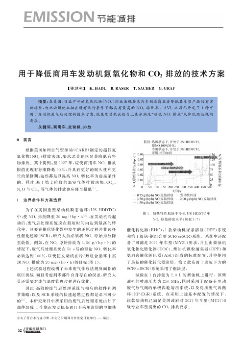
用于降低商用车发动机氮氧化物和C O 2排放的技术方案ʌ奥地利ɔ K.H A D L B .R A S E R T .S A C H E R G.G R A F摘要:在美国,日益严苛的氮氧化物(N O x )排放法规要求汽车制造商显著降低其车型产品的有害物排放,为此必须使车辆在所有运行条件下都具有最高的N O x 转化率㊂A V L 公司已开发了1种可用于发动机废气后处理的技术方案,能在发动机试验台上充分满足 超低N O x 排放 及降低燃油耗的要求㊂关键词:商用车;发动机;排放①为了符合本行业习惯,本文仍沿用部分非法定计量单位 编注㊂0 前言根据美国加州空气资源局(C A R B )制定的超低氮氧化物(N O x )排放法规,要求北美地区显著降低有害物排放㊂其中提到:至2027年,应使商用车N O x 排放限值比现有标准降低90%,并具有更好的耐久性和更长的保修期,这些都是以提高N O x 转化率为前提条件的㊂同时,基于第2阶段的温室气体排放法规,C O 2㊁N 2O 与CH 4等气体的排放也应降至最低[1]㊂1 边界条件和方案选择为了在美国重型柴油机瞬态循环(U S H D D T C )中,使N O x 排放降至20m g /(h p ㊃h )①,在发动机冷起动后,废气后处理系统应在最短时间内达到最高的转化率㊂只要在催化转化器中发生的还原过程并非选择性催化还原(S C R ),研究人员必须将N O x 原始排放降至最低㊂例如,在N O x 原始排放为3.50g /(h p ㊃h )的情况下,废气后处理系统在50s 后的理论N O x 转化率必须达到100%,以便使发动机在冷/热组合循环中实现N O x 排放为20m g /(h p ㊃h )的目标(图1)㊂上述试验过程说明了未来废气排放法规所面临的艰巨挑战,而且考虑到零部件自身存在的误差,研究人员还需要对废气温度管理过程进行优化㊂因此,高效的废气后处理系统与相应的软件和调节策略,以及S C R 系统的快速起燃过程都是必不可少的[2]㊂本研究项目中所采用的废气后处理系统由如下部件组成:1个靠近发动机布置且不采用涂层的电加热图1 加热特性取决于冷机U SH D D T C 中N O x 原始排放水平(加权1/7)催化转化器(E H C ),1款柴油机尿素溶液(D E F )系统和第1级钒-铜组合型S C R (c c S C R )系统㊂系统中还配备了可满足2021年车型(MY 21)要求,并且由柴油机氧化催化转化器(D O C )㊁柴油机颗粒捕集器(D P F )和氨逃逸催化转化器(A S C )组成的标准配置,其中使用了最新的催化转化器涂层㊂第2款布置于底板下方的S C R (u f S C R )系统采用了铜涂层㊂试验在1台排量为2.0L 的柴油机上进行㊂该柴油机的喷油压力为250M P a ,同时采用了配备有电动废气放气阀的单级涡轮增压系统,以及高压废气再循环(H P -E G R )系统㊂在采用上述基本配置的情况下,该款柴油机已满足美国政府对2027年车型(MY 27)8级专业车型提出的C O 2排放要求㊂25 2021年第6期522021 NO.6汽车与新动力2 加热策略和温度管理研究人员选用了配有冷却系统的H P -E G R 系统,并采用了节气门辅助,因此在系统冷起动后就直接能使N O x 原始排放降至最低㊂同时,研究人员提高了进气管中的温度,使废气流量相应降至最低,最终使经过E H C 的气体温度得以有效提升㊂在废气流量较小的情况下,功率为7k W 的加热系统具有较好的加热效果,而在废气流量较大的情况下,其效果并不显著(图2)㊂图2 冷态U SH D D T C 前600s 内的加热策略研究人员通过采用未配有冷却设备的H P -E G R系统,同时降低废气流量,并与E H C 相组合,可在冷态U SH D D T C 的前600s 内使N O x 原始排放降至约1.50g /(h p ㊃h )㊂正如图2所示,在冷态U S H D D T C 中的首次加速阶段,系统对N O x 的转化效果已较为显著,而在第2次加速阶段以后,N O x 的转换效率就已超过了99%㊂研究人员通过选用未配有冷却设备的H P -E G R 系统,不仅改善了发动机在加热期间较低的燃油耗,而且还改善了D PF 的再生效果㊂3 基于U SH D D T C 的试验结果为了在D E F 消耗量较低的同时实现较低的N O x排放,研究人员需要采用以下几方面的策略:(1)对催化转化器部件进行设计与优化;(2)应用新型涂层技术;(3)为两级S C R 系统选用先进的软件和调节策略;(4)实现催化转化器的D E F 计量过程;(5)对NH 3加注量进行高精度建模;(6)开展相应的标定试验㊂由A V L 公司开发的软件和调节策略不仅能在N H 3逸出量较少且N 2O 排放量较低的同时进一步提升N O x 的转化率,而且还能通过基于模型的虚拟传感器对整个废气后处理系统进行物理建模,以降低系统成本[3-4]㊂除此之外,研究人员通过已开发的算法,并根据当前或未来废气后处理系统的状况,将转化N O x 的任务分配到两级SC R 系统上㊂只要满足相应的认可条件(温度㊁炭烟量㊁N 2O 等),第1级S C R 系统便可从基于N H 3加注状况而设定的运行模式转换到基于效率而设定的运行模式上,从而有针对性地实现了较高的N O x 转化率,以支持D P F 系统的被动再生过程,同时延长D P F 再生间隔(图3)㊂在低负荷循环中,前1级的S C R 系统主要基于N H 3的加注状况而运行㊂使用E H C 能确保第1级S C R 系统被迅速加热,从而有效地降低发动机在冷态运行时的排放㊂即使在热态U SH D D T C 中,系统也会在短期内使用E H C ,以便确保系统在短期内达到最高的N O x 转化率㊂在试验室条件下,研究人员通过采用现有的发动机和废气后处理方案就能满足降低N O x 排放的要求,而在冷/热态组合U S H D D T C 中的排放能降至18m g /(h p㊃h ),同时研究人员通过选择调节策略也能使N 2O 排放保持在较低的水平㊂在该方面,后者还可将其他催化转化器技术或铁/铜S C R 组合用于第2级S C R 系统,并进一步优化㊂研究人员通过对发动机进行调节,就能使其以低燃油耗的模式运行㊂与MY 21基础相比,发动机在U SH D D T C 中的燃油耗多出了1%(图3)㊂事实上,通过将内燃机输出的机械功转换为电能,即可满足系统需求,在U SH D D T C 中也能满足美国政府对MY 278级专业车型提出的C O 2排放要求㊂特别是在倒拖行驶阶段中,研究人员通过采用相应的智能充电策略,充分利用车辆动能,显著降低了整车燃油耗㊂研究人员通过优化部件的配置,就能明显加快催化转化器的起燃速度,从而进一步降低排放㊂4 不同废气后处理系统的技术潜力为了降低系统的复杂性和硬件的成本,研究人员选用尚未配备E H C 的两级S C R 系统进行了试验㊂虽35 2021年第6期532021 NO.6汽车与新动力图3 基于U SH D D T C 的发动机运行策略和D E F 系统计量调节的结果然在该情况下也能达到最高的N O x 转化率,但是现有的发动机和废气后处理系统如果并未配备E H C ,就不可能满足20m g /(h p ㊃h )的超低N O x 排放限值要求(图4)㊂尚未配备E H C 的两级S C R 系统的缓慢加热特性主要会对发动机在冷态运行时的排放造成影响,而在热态U SH D D T C 中所检测到的排放增加情况则并不明显㊂由于N O x 转化过程会被分配到2个不同的S C R 级上,因此剩余的N 2O 排放也将维持在较低水平㊂发动机在采用单级S C R 系统的情况下,同样也能有效降低排放㊂研究人员通过将未配有冷却设备的H P -E G R 系统和最新的涂层技术相组合,使试验发动机图4 不同废气后处理系统对排放的改善效果在U SH D D T C 中的N O x 排放降至35m g /(h p ㊃h )㊂与原机型相比,试验发动机的这一数据得以明显降低,其中也体现出H P -E G R 系统在采用了冷却设备后的优势㊂发动机在冷态运行状态时产生的N O x 原始排放较低,并可用于为系统保温㊂单级S C R 系统在加热模式下得以长期运行,可有效降低N O x 原始排放㊂与两级S C R 系统相比,N O x 原始排放也会相对较低,相比较高的N H 3加注量,会导致较高的N 2O 排放,但是后者通过采用其他的催化转化器技术或组合应用铁/铜S C R系统,可实现进一步优化,满足法规限值要求㊂5 发动机在低负荷循环中的性能表现发动机在低负荷循环中的性能表明,采用单级S C R 系统或两级S C R 系统都能达到最低的排放(图45 2021年第6期542021 NO.6汽车与新动力5)㊂使用E H C 能使S C R 催化转化器的温度保持在200ħ以上,因此其排放也更接近指示限值㊂由于单级S C R 系统被加热的总质量较小,因此其呈现出了较高的温度梯度,同时也显示出较快的加热特性和冷却特性,以及较高的N 2O 排放㊂对于所有参与试验的废气后处理系统而言,其能充分满足2024年车型(MY 24)生效的低负荷循环要求㊂图5 不同废气后处理系统在低负荷循环中的试验结果6 针对废气后处理系统的认证过程由试验发动机产生的排放有望进一步降低,但同时也面临着艰巨的挑战,其要求车辆在整个使用寿命期内都要满足超低的N O x 排放要求㊂为了对较高的开发费用和认证费用进行优化,A V L 公司开发并设立了可用于废气后处理系统的6步认证程序(图6)㊂在方案设计阶段,研究人员借助于A V L 公司的软件平台巡航系统模型开展了试验,同时确定了车载诊断(O B D )系统方案,并研究了不同参数对系统可靠性所产生的影响㊂即使在软件开发过程和后续的系统标定过程期间,研究人员也应持续使用模型来开展研究㊂同时,模型的完善程度也在持续优化中,特别是在评估软件功能和标定工作期间,研究人员须使模型在成本㊁时间计图6 基于模型的废气系统认证方法划和效率等方面具有显著的优势㊂此外,在发动机试验台上进行的试验认证可用于模型预测,并可作为在使用寿命期间缓解老化效应及提升排放稳定性的基础㊂认证期间获得的结果可用于为学习功能提供数据,从而补偿产品偏差与老化效应产生的影响㊂研究人员在试验过程中采用了模型,从而显著优化了试验程序,并减少了试验数量㊂除此之外,模型还能持续用于整车标定及系统对车辆的监测㊂考虑到未来法规的影响,以模型为基础的6步认证程序能为提升产品的可靠性及耐久性作出重要贡献㊂7 结论和展望试验研究表明,研究人员将不采用冷却设备的H P -E G R 系统与两级S C R 系统和电加热催化转化器相组合,可在试验室条件下使排放降至最低㊂在试验发动机上,U S H D D T C 条件下的N O x 排放会降至18m g /(h p㊃h ),而低负荷循环的排放则接近指示限值,此外两级S C R 系统可在满足MY 278级专业车型的C O 2排放目标限值的同时,呈现出较低的N 2O 排放㊂由A V L 公司开发的软件和调节策略能在确保N H 3逸出量较低的同时达到较高的N O x 转化率,并可将N O x 转化过程分配到两级S C R 系统中,以此支持D P F 系统实现被动再生,从而可获得更高的诊断自由度㊂此外,基于模型的方法还能有效地为学习功能提供数据㊂作为用于替代E H C 的其他方法,研究人员还可采用停缸法,或者采用能使排气门实现早开的可变气门机构㊂在试验发动机上使用单级S C R 系统或两级S C R55 2021年第6期552021 NO.6汽车与新动力(无E H C)系统有着较好的应用前景,并可用作于使N O x排放限值降至50m g/(h p㊃h)的折中方案㊂试验研究表明,降低车辆在整个使用寿命周期内的N O x排放是1项艰巨的挑战㊂在该方面,由A V L 公司开发的废气后处理系统认证程序,为提升产品的可靠性及耐久性提供了重要的技术支持㊂参考文献[1]D R E I S B A C H R,W I E S E R M,S E I T Z H,u.a.50%w i r k u n g s g r a da m v e r b r e n n u n g s m o t o r-d i e r e a l i s i e r u n g e i n e r v i s i o n[C].7t h I n t e r n a t i o n-a l e rM o t o r e n k o n g r e s s,B a d e n-B a d e n,2020.[2]E D V A R D S S O NJ,H A D L K,T H E I S S L H,e ta l.H Dd i e s e l e n g i n e-e x h a u s t g a s t e m p e r a t u r em a n a g e m e n t a n da d v a n c e de x h a u s t g a sa f-t e r t r e a t m e n t t e c h n o l o g y f o ru l t r a-l o w N O x e m i s s i o nl e g i s l a t i o n[C]. 7t h I n t e r n a t i o n a l e rM o t o r e n k o n g r e s s,B a d e n-B a d e n,2020. [3]G R A F G,T H E I S S L H,H A D L K,e ta l.L o w e s tC O2e m i s s i o n sd e-s p i t eu l t r a-l o w N O x[C].10t h I n t e r n a t i o n a lC o m m e r c i a lP o w e r t r a i nC o n f e r e n c e,G r a z,2019.[4]D E M O N T E M,MA N N S B E R G E R S,N O L L H,e ta l.S C Rc o n t r o l s t r a t e g i e sw i t hm u l t i p l e r e d u c t i o nd e v i c e s f o r l o w e s tN O x e m i s s i o n s [C].S A E H e a v y-D u t y D i e s e lE m i s s i o n sC o n t r o l S y m p o s i u m,G o t h-e n b u r g,2018.范明强译自 MT Z,2021,82(3)伍赛特编辑(收稿时间:2021-03-19)652021年第6期56汽车与新动力。
发动机排气后处理技术

一、排气后处理的原因与意义随着我国工业快速崛起与经济迅猛发展,我国人民的生活水平不断提高,对于生活品质的要求也越来越高,汽车作为一种非常便捷的交通工具也越来越普及,汽车工业也得到了飞速的发展。
然而,汽车的普及与汽车工业的快速发展给人们生活带来便利的同时也产生了能源与环境问题。
近年来,节能、能源与环境相容问题成为备受关注的重大科学问题。
而汽车发动机作为汽车动力的问题的根本所在,因此改善汽车性能的关键在于开发汽车发动机节能减排技术。
因而,随着对内燃机低排放的要求不断严格,能兼顾动力性、经济性、排放性的内燃机越来越复杂,成本急剧上升。
因此,世界各国都先后开发排气后处理技术,在不影响或者少影响内燃机其他性能的同时,降低最终向大气环境的排放。
如何解决好发展过程中的能源与环境问题成为当前汽车工业面临的两项难题。
一直以来汽车发动机以石油作为主要的燃料来源,但是,石油资源具有不可再生性,连续开采已使得石油资源日益枯竭。
尾气排放带来的环境污染问题也是汽车工业急需解决的问题,制定并实施汽车尾气排放标准是一项较为有效的控制措施。
在能源与环保的双重压力下,我国汽车发动机行业引进了许多先进的技术。
就汽车发动机而言,汽车发动机排气后处理技术等先后应用到实际的生产生活中,其技术可以有效改善汽车发动机的尾气的排放与污染,降低废气污染的排放。
进入二十一世纪,世界汽车发动机技术的研究重点与目标趋向于节能和二氧化碳减排取代排放控制的方面上。
因此发动机排气后处理技术正处于上升趋势,而且国际上发动机排气后处理技术近年来已经有了很大的提高,其基础理论与机制有了巨大的进步,因此研制、设计、和试验汽车发动机系统的技术得到了很大的革新。
二、排气后处理技术的原理与分类在讨论汽车发动机排气后处理技术之前,我们应该首先讨论一下汽车发动机所排放的尾气与其对于人体与社会的危害。
首先汽车发动机的尾气的主要危害物有一氧化碳、碳氢化合物与氮氧化合物等众多有毒有害的气体。
- 1、下载文档前请自行甄别文档内容的完整性,平台不提供额外的编辑、内容补充、找答案等附加服务。
- 2、"仅部分预览"的文档,不可在线预览部分如存在完整性等问题,可反馈申请退款(可完整预览的文档不适用该条件!)。
- 3、如文档侵犯您的权益,请联系客服反馈,我们会尽快为您处理(人工客服工作时间:9:00-18:30)。
ICPC 2007 - 2.1 Exhaust Gas Aftertreatment Systems for Commercial Vehicles – Technologies and Strategies for the FutureDipl. Ing. Wolfgang MausDipl. Ing. Rolf BrückEMITEC GmbH Copyright © 2007 AVL List GmbHABSTRACTMore stringent emission legislation, particularly with regard to particulate and nitrogen oxide (NOx) emissions, is currently being discussed in Europe. In view of American US2010 emission legislation there is a call for the introduction of stricter limits in Europe by 2012 (EU VI). The question concerning commercial vehicle manufacturers and automotive suppliers is what direction the development should take. The experience from EU IV and EU V applications clearly shows that the requirements of EU VI cannot be met solely by new engine developments that aim to reduce particulate and/or NOx emissions, but require a cost-effective overall solution that includes exhaust gas aftertreatment. The reduction of these emissions has to be seen in the light of the trade-off with CO2emissions, especially in commercial vehicle applications, since the resulting fuel consumption has a significant effect on operating costs. The possible scenarios for future emission concepts are discussed and illustrated by means of examples below. IntroductionEuropean directives on immission loads in cities are an effective tool for the implementation of further demands for environmental protection. Since cities and other local authorities have to demonstrate that they have done everything in their power to comply with these directives, current debate has widened to include the creation of environmental zones or the exclusion from the affected cities of cars falling into a certain emission category. The example of the clean air directive showed that it was possible to propose additional requirements and implement them with public backing in spite of existing emission limits, which in the case of cars applied until 2010. One of the consequences of this pressure was the early introduction of particulate filters in vehicles that already met current legislation through engine-based measures alone.This also explains why the tightening of the NO2 directive due in 2010 had a direct effect on EU5 and EU6 limits for cars and is subsequently going to shape the future European EUVI limits for trucks. The European Commission is expected to issue its first official proposals in autumn 2007. A variety of scenarios were put forward by legislators and car manufacturers prior to the publication of these proposals. The general tenor seems to be that the limits would approximate the American US2010 limits, at least in the long term. However, apart from emission limits the debate also focuses on the replacement of the current test cycles by a world harmonised test cycle (WHTC), which includes cold starts, and on the introduction of a new particulate number limit. Both measures have to be clearly defined and evaluated by comparing them to current test and measuring methods as they are going to have a great impact on future catalyst and filter technology.Current emission limits regulate the emission levels of hydrocarbons (HC), carbon monoxide (CO), nitrogen oxide (NOx) and particulate matter (PM). Increasingly serious discussions about climate change will be followed by demands for the lowest possible CO2emissions. Fuel consumption and hence CO2 emissions have always been a priority in the commercial vehicle industry since both have a significant effect on the cost-effectiveness of vehicles.In order to meet future emission limits – for instance, the American US2010 limits since European limits have not yet been agreed – an economically optimum overall solution that combines engine technology and exhaust gas aftertreatment will have to be developed.One of the objectives of future engine developments has to be the reduction of emissions without raising fuel consumption. State-of-the-art engine components are the only solution and are likely to increase the costs of the overall system. A combination of engine-based measures and a suitable, low-pressure loss, lightweight exhaust gas aftertreatment system opens up opportunities for innovative, economically viable overall solutions that are likely to further reduce CO2 emissions.The development of engine raw emissionsAs mentioned above, it is impossible to look at engine design, including related raw emissions, or the catalyst system in isolation when it comes to extremely stringent emission limits. Engine-based measures that reduce raw emissions lead to simpler, lighter and perhaps even more reliable exhaust gas aftertreatment systems. The modification of an inexpensive EU III engine with typical raw emissions to enable it to meet US2010 NO x emission limits without exhaust gas recirculation would require a SCR system (Selective Catalytic Reduction system) with a minimum effectiveness above 93%. Since this value would have to be achieved not only when the system was new but over the entire service life of the vehicle, legal compliance would require enormous effort according to currently available data. In terms of long-term stability a modern SCR system can realistically achieve an efficiency of 75 to 85%. This seems to indicate that engine designs with state-of-the-art engine components to reduce raw emissions will become the worldwide standard, starting in Europe, the US and Japan.In addition to the basic design of the combustion chamber and the combustion process, technical papers on engine developments mainly focus on the following measures to reduce raw emissions:- High-pressure fuel injection with more than 2500 bar- Two-stage turbocharging- Controlled and cooled exhaust gas recirculation with recirculation rates over30%High, cooled EGR rates (Exhaust Gas Recirculation) especially lead to vehicle follow-up costs since the available cooling capacity is generally insufficient and therefore has to be increased. The requirements for the control quality of the recirculated exhaust gas also increase with regard to quantity and temperature. Any deterioration in cooling capacity primarily affects NO x raw emissions. EGR catalysts protect against sooting and hence increase the durability of the coolers [1] and the control valves. The sum of these measures is a reduction of both critical NO x emissions and particulate emissions [2,3]. The use of EGR beyond a certain limit is generally regarded as critical to fuel consumption. However, this is offset by an increase in turbocharging pressure [4] so that the first available engines are even more fuel-efficient than engines without EGR [5]. The extent to which these investments in engine technology are financially viable as part of an overall solution does not least depend on the required or feasible catalyst or filter system.Figure 1 shows the NO x/particulate trade-off curves of various engine designs with possible exhaust gas aftertreatments. The data was based on raw emissions from currently available or certified engines. EU V and US2007 limits were included to illustrate current requirements or requirements that apply until 2010 in the US and 2012 in Europe.Figure 1: NOx/particulate trade-off of currentlyavailable engines and thecatalyst/filter technologies requiredfor EU V and US2007 limits Depending on raw emissions or the design point, there are a number of possible scenarios that can achieve the required conversion rates with regard to the reduction of particulates and NO x. For instance, a PM-optimised non-EGR engine is able to meet EU V limits with a SCR system (with a conversion rate of 60%). A NO x-optimised EGR engine can be made to comply with EU V limits following the installation of a partial-flow deep-bed filter (PM-METALIT TM) [6,7], while the same engine would require a wall-flow filter to meet US2007 limits.The design of a scenario for the future must be based on an evaluation of ongoing engine developments and post-2012 limits. In the absence of defined European limits the emission targets were based on the American US2010 values.Figure 2 shows the NO x/particulate trade-off curves of various new engines, some of which are not yet in production, as a function of the applied technology [8,9].Figure 2: NO x/particulate trade-off of variousnew engines and the catalyst/filtertechnologies required to meetUS2010 limitsIt is assumed that the aim of each engine design is to minimise fuel consumption by fully exploiting the highest possible NO x reduction rates. In terms of long-term stability the maximum conversion rate of the SCR system considered in this paper was assumed to be 80%. This results in particulate reduction rates between 65 % and 86% depending on engine technology and related raw emissions. 3. Catalyst technology3.1 Nitrogen oxide reductionThere are essentially two technologies available today to reduce nitrogen oxides. The first is the above-mentioned SCR technology, and the second is NO x storage technology. Both methods have been developed to the production stage, however, series production experience is only available for commercial vehicles with SCR systems. In the second case fuel consumption rises because NO x adsorbers regenerate at brief intervals during phases with a rich exhaust gas mixture and also have to be desulphated at regular intervals at a temperature around 650°C. The substrates also have to be relatively large so that the intervals between the rich regeneration phases do not become too short. The high precious metal content of these substrates means that the costs for typical commercial vehicle engine applications are relatively high. These two drawbacks are reasons against their future production. Therefore this paper deals exclusively with SCR technology.The “Selective Catalytic Reduction” of nitrogen oxides under lean operating conditions, i.e. in the presence of excess oxygen, by means of ammonia (NH3) has been used in the chemical industry or the aftertreatment of power station emissions for decades. In the automotive industry the SCR system was initially developed for and used in commercial vehicles. Apart from increasingly stricter emission limits the reasons also included a possible change in the ratio between NO x and particulate emissions when adjusting the engine in favour of lower fuel consumption, i.e. towards higher NO x emissions. The aim of the development at that time was to find an additional financial incentive to promote the sale of this type of engine. Since the engines themselves continued to undergo further development at the same time and similar advantages could be achieved almost solely on the basis of engine-based measures, the start of SCR series production was repeatedly delayed. The requirement to carry another operating material in the vehicle, in this case an urea-water solution (AdBlue) to generate ammonia onboard, added to the delays. The situation was made worse by the fact that the necessary logistics for the reduction agent had to be set up from scratch.A typical SCR system consists of a reduction catalyst, urea injection and dosing components, pipes and a storage tank. Some systems also include an upstream oxidation catalyst, a hydrolysis catalyst and, if necessary, a downstream ammonia trap.Most modern catalysts are extrudate catalysts or coated ceramic catalysts with vanadium pentoxide as the catalytically active component. Catalytic coatings on a zeolite basis are currently being developed because of the limited temperature stability of these catalysts and the fact that vanadium pentoxide has been classified as a health risk in some countries. The coating technology for the substrates corresponds to the well-known processes used in the production of three-way or oxidation catalysts. Increased temperature stability is especially important in SCR catalysts installed behind a particulate filter since relatively high temperatures are generated during filter regeneration. Zeolite catalysts are highly sensitive to the NO2/NO ratio in the exhaust gas especially at low temperatures. Since zeolite SCR systems are most efficient at a ratio of 1-1 they must include an oxidation catalyst because the engine emits almost exclusively NO.One of the problems of current SCR systems is the injection and equal distribution of the urea-water solution that is introduced into the exhaust gas stream as a finely dispersed liquid. The larger thesize of the droplets the longer it takes for them to evaporate in the exhaust gas. This factor plus radially uneven droplet concentrations in the gaseous phase can lead to concentration differences on the catalyst surface resulting in reduced conversion rates. The use of “turbulent” catalyst substrates with radial flow and concentration equalisation offers a significant improvement. Figure 3 shows turbulence-generating catalysts with a PE, LS/PE and MX design.Figure 3: “Turbulent” catalyst substrates with a PE,LS/PE and MX design [10, 11] 3.2 Particulate reductionThere are currently two major filter systems in production that can be used to reduce particulate matter. The first is the classic wall-flow filter [12, 13]and the second is Emitec’s PM-METALIT TMpartial-flow deep-bed filter, which passively regenerates on a continuous basis.Wall-flow filters have a filter efficiency of over 98% after building up a filter cake. The filter has to be actively thermally regenerated at regular intervals at temperatures above 550 - 600°C. Since the temperature in the exhaust gas of commercial vehicles does not rise to these levels under normal conditions, fuel is added in front of the oxidation catalyst either by post-injection in the combustion chamber or via a separate fuel injector in the exhaust gas system. This fuel heats the exhaust gas through an exothermic reaction in the catalyst. Pressure loss changes between an actively regenerated and hence unloaded state and a loaded state at regular intervals.Thermal regeneration increases the temperature load of both the oxidation catalyst and the downstream SCR catalyst behind the particulate filter from typically 550°C (without active regeneration) to 750°C in active systems. In this method, fuel consumption is raised by the necessary regeneration on the one hand and the regular increase in pressure loss on the other [14]. Depending on its design and size, the filter shouldbe able to operate reliably for more than 500,000 km as largely harmless ash is filtered from the oil or fuel and blocks the filter [15]. As a result, operators may be faced with additional costs and possibly even vehicle downtimes.Emitec’s PM-METALIT TMpartial-flow deep-bed filter (figure 4) has been used in commercial vehicles and cars over the past two years. The MAN EU IV, fittedwith a PM-METALIT TM, has worked reliably in over 60,000 vehicles. The filter has operated over 800,000 kilometres without malfunction or having tobe cleaned. The PM-METALIT TMis the only mass-produced OEM filter system on the market worldwide that is designed for the entire service life of the engine without needing further maintenance.Figure 4:PM-METALIT TMpartial-flow deep-bed filter and soot conversion rate of a 300 mm long filter in the ESC cycleThe filtered soot is burnt on a continuous basis using the NO 2 contained in the exhaust gas or generated in the oxidation catalyst.The efficiency of the filter in relation to the soot mass is between 50% and 80% depending on filter length [16]. The reduction of the particle number in the 10 – 300 nm range is between 80 and 95%. 3.3 The oxidation catalystOxidation catalysts are used to reduce HC and CO emissions. In addition, NO is oxidised to form NO 2 at a temperature between 200 and 450°C. The NO 2 can be used to burn up particulates or to improve the low-temperature efficiency (180 – 350°C) of zeolite SCR catalysts. Oxidation catalysts have either a Pt or a Pt/Pd coating depending on the temperature load.In a highly efficient SCR system there is a risk of ammonia slip behind the SCR catalyst. This can be prevented by fitting an oxidation catalyst behind the SCR catalyst or by applying an oxidation coating to the rear part of the SCR catalyst in order to oxidise the NH 3. A sensor catalyst represents a good solution. This design involves a NH 3 sensor integrated in the metal catalyst substrate resulting in more catalyst volume behind the sensor to prevent NH 3 slip.Depending on the choice of filter system the oxidation catalyst is also used to generate the necessary exothermic energy for the regeneration of the wall-flow filters. The fuel required for this is either supplied by fuel post-injection via injection nozzles or by a fuel injection nozzle in the exhaust stream behind the engine. Oxidation catalysts with internal flow equalisation (figure 3) are particularly efficient at minimising HC slip since they are able to equalise any uneven fuel distribution.The thermal capacity of the oxidation catalyst should also be as low as possible since it acts as an inert mass and delays the heating of the particulate filter, thus extending regeneration times.HC efficiency is shown in figure 5a while the HC slip of a standard oxidation catalyst compared to a catalyst with an LS/PE structure is shown in figureFigure 5a:HCefficiency in front ofthe particulate filter of astandard 300-cpsi catalyst compared to a 300/600-cpsi LSPE catalystFigure 5b:HC slip of a standard 300-cpsi catalyst compared to a 300/600-cpsi LSPE catalyst3.4 The hydrolysis catalystAccording to research the installation of a hydrolysis catalyst in the partial flow allows to reduce significantaly the size of the SCR catalyst, which is normally used for hydrolysis in the full stream, especially at low temperatures. The reasons for this are the longer contact time in the partial-flow hydrolysis catalyst and the obstruction of the hydrolysis caused by the presence of NO 2 generated in the upstream oxicat (figure 6).Figure 6:Effect of NO 2 on the efficiency of the hydrolysis [17]Research carried out at the Paul Scherrer Institute (PSI) shows that efficiency is significantly reduced in the presence of NO 2 especially at temperatures between 150 and 225°C. The effect should be almost negligible because exhaust gas temperatures generally rise above 300°C in modern commercial vehicle engines and during hot tests. The exhaust gas temperature of future engines is going to be considerably lower (figure 7a). If one additionally takes the WHTC, which is to be introduced in Europe at least, into consideration, temperature levels will be even lower due to engine loads. A cold test also has to be carried out. Figure 7b shows the temperature curve of an engine without catalyst heating in the WHTC.Figure 7a: Comparison between the exhaust gastemperatures in front of the catalyst of a production engine and an US2007 engine in an ESC test.Figure 7b: Exhaust gas temperatures in the WHTCtest with a production engine without catalyst heating (cold and hot test) This clearly shows that the effect of NO 2 has to be included in future concepts if the aim is to produce a very compact, cost-effective catalyst system. One option is for hydrolysis to take place in the partial flow of the main exhaust gas stream. Figure 8 shows a possible partial-flow hydrolysis system. The hydrolysis catalyst is placed inside a metal ring catalyst. Urea is centrally injected. The size of the partial flow is determined by the area ratio of the central hydrolysis catalyst compared to the circular oxidation catalyst and by the structure of the respective substrates. The hydrolysis coating can consist of a thin titanium dioxide layer, which is able to evaporate any remaining AdBlue droplets without sustaining any damage.Figure 8:Partial-flow hydrolysis system with a concentric ring catalyst and urea injection in the centre.In very cold applications an electrically heated catalyst may be fitted upstream from the hydrolysis catalyst in order to raise the exhaust gas temperature during critical operating conditions. 4. Design of US2010, EU VI exhaust gas system The following two scenarios for potential US2010 or EU VI systems are based on the engine technology or raw emission levels shown in figure 2 and a notional maximum NO x reduction of 80% with long-term stability:a)Engines with NO x emissions of 1.6 g/kWh and PM emissions of 0.10 g/kWh (cooled, controlled EGR, single-stage turbocharging, injection pressure 1800 bar)b)Engines with NO x emissions of 1.6 g/kWh and PM emissions of 0.04 g/kWh (cooled, controlled high EGR, two-stage turbocharging, injection pressure 2500 bar)In design a) the engine is moved along the characteristic curve at the expense of particulate and CO 2 emissions in order to achieve NO x raw emissions of 1.6 g/kWh.The improved raw emission levels of a high-EGR engine with two-stage turbocharging and an injection pressure of 2500 bar (design b)) are initially accompanied by higher engine costs. However, in contrast to design a) this design allows fuel consumption and hence CO 2 emissions to be reduced because of higher charging pressures and a correspondingly improved lambda.The aim of the assessment that follows below is to illustrate and evaluate the effect of engine design on the costs of exhaust gas aftertreatment systems and fuel consumption affected by the exhaust gas aftertreatment.The evaluation takes account of current ESC and FTP tests and also the WHTC with cold start, which is currently being discussed.Apart from emissions, the primary development objective is a reduction in fuel consumption and hence CO 2 emissions. This means, for instance, that the particulate filter dealt with below is installed in front of the NO x catalyst in order to exploit the CRT effect, which reduces the filtered soot quantities and so also the number of active regeneration phases with fuel injection.A corresponding exhaust gas system would consist of an oxidation catalyst, a hydrolysis catalyst – in a bypass if necessary – (see figure 8), a particulate filter and a downstream SCR catalyst with an integrated NH 3 trap, if necessary.In a catalytically coated particulate filter urea injection and hydrolysis must take place behind the filter since the generated ammonia would otherwise react with the platinum and therefore no longer be available for the SCR reaction.The design of the SCR catalyst, or the type of coating, depends on whether an actively regenerating particulate filter or a continuouslyregenerating filter system is to be used. Since temperatures can peak above 750 – 800°C during active regeneration (s.a.) a temperature-resistant zeolite coating should be used in this case. Since the efficiency of current zeolite coatings is highly dependent on the NO 2 content in the exhaust gas at temperatures below 350°C [17] the NO 2 concentration must be included in the overall SCR metering control. This factor must be critically examined especially with regard to the planned WHTC with cold test and new engines with significantly reduced temperature levels (figure 7b). The maximum exhaust gas temperature of a continuously regenerating filter system is approx. 550°C permitting the use of a vanadium pentoxide coating as an alternative active component. The efficiency of this type of coating is less dependent on the NO 2 content especially at lower temperatures and the coating is also much less expensive. A test carried out at the University of Kaiserslautern showed that the vanadium pentoxide coating applied to a standard 300-cpsi metal substrate was as efficient in relation to temperature as a 300-cpsi full extrudate [18]. On the basis of these results a 300-cpsi full extrudate was compared to a “turbulent” metal catalyst with a 300/600 LSPE structure. The volume of the metal catalyst was reduced by 39 % to 13.2 litres to take account of the improved mass transfer of the “turbulent” structure and the internal concentration equalisation. The hydrolysis took place in an upstream hydrolysis catalyst in the partial flow. In addition, an oxidation catalyst had been installed in the main flow.Figure 9 shows the emission results in relation to the injected urea quantity. The two catalysts produced similar results. The “turbulent” SCR metal catalyst achieved conversion rates over 90% despite its considerably smaller volume.Figure 9:NO x conversion rate in relation to the urea quantity of a full extrudate and a “turbulent” metal catalyst.4.1 Exhaust gas system for engines with NOx emissions of 1.6 g/kWh and PM emissions of 0.10 g/kWhThese engines have to achieve NO x conversion rates of 80% and a particulate reduction of 86% in order to meet US2010 limits. According to figure 9 the SCR volume required for “turbulent” metal catalyst substrates corresponds to the engine’s cubic capacity.According to currently available data a particulate reduction of 86% can only be achieved by a wall-flow filter that has been adapted to commercial vehicle applications. Figure 10 shows the layout of the exhaust gas system.Figure 10: Layout of the exhaust gas system for a low-NO x , high-PM engineWall-flow filters regenerate at regular intervals at temperatures above 600°C (s.a.). The regeneration intervals depend on raw emissions and filter volume. A commercial vehicle for long-distance transport emits approx. 16.7 g of soot per 100 km at an average performance of 100 kW/h and an average speed of 60 km/h. At a maximum filter load of 8 g/l and a notional passive CRT efficiency of 60% the following regeneration intervals apply depending on filter volume: Filter volume 10 l 20 l Regeneration interval 1200 km2400kmAt present there is practically no data on fuel consumption raised by regeneration in commercial vehicles. Therefore a comparison was made on the basis of car data at this point. The fuel consumption of a car with a regeneration interval of approx. 1000 km rises by approx. 2 – 3% [19]. As a result, the fuel consumption of a commercial vehicle is likely to increase by 1.5% based on the regeneration interval of a 20-litre particulate filter. This assumption is based on the fact that compared to a car the relative additional consumption of a commercial vehicle would be partially offset by a correspondingly larger filter volume that has to be heated. The effect of the pressure loss, which isincreased by the filter load, was not considered. However, it can be assumed that a 100-mbar increase in backpressure would raise fuel consumption by approx. 1% leading to an expected overall increase in fuel consumption of approx.2.5%. Regeneration also requires a fuel injection nozzle in the exhaust gas system and the installation of pressure sensors that measure load conditions. Over the next few months precise data on fuel consumption will become available from US2007 applications.Vehicles will still have to be taken to the workshop at regular intervals so that the deposited ash can be removed from the wall-flow filters otherwise regeneration intervals would be drastically reduced and the pressure loss would continue to increase. The cleaning intervals are directly determined by oil consumption and the ash content of the oil. The oil consumption of a modern commercial vehicle engine with a fuel lubricated injection pump is approx. 0.2 litres per 1000 km (0.175 kg per 1000 km)The amount of ash produced by low-ash oil with an ash content of 1% is 1.75 g per 1000 km or 0.88 ml per 1000 km. Classic 200-cpsi particulate filters with a wall thickness of 12 mil (0.3 mm) and a symmetrical cell size, as those currently used in commercial vehicles, have a free gas inlet channel volume of 0.34 litres per litre of filter.This means that 1 litre of particulate filter is filled with ash after the vehicle has travelled a distance of approx. 385,000 km.4.2 Exhaust gas system for engines with NOx emissions of 1.6 g/kWh and PM emissions of 0.04 g/kWhThese engines must achieve NO x conversion ratesof 80% and a particulate reduction of 65% in order to meet US2010 limits.In contrast to 4.1, at a particulate reduction of 65% a maintenance-free partial-flow filter offers the best solution in view of the above raw emission levels. Figure 11 shows the layout of the exhaust gas system.Figure 11: Layout of the exhaust gas systemfor the low-NO x, low-PM engine In contrast to the exhaust gas system of low-NO x/ high-PM engines, the urea injection unit is positioned in front of the partial-flow filter. The partial-flow filter can optionally be coated with titanium dioxide and function as a hydrolysis catalyst. Since the hydrolysis would otherwise have to take place in the front part of the SCR catalyst it is possible to reduce the SCR catalyst volume without any detrimental effect on the conversion rate.The PM-METALIT TM partial-flow deep-bed filter reduces particulate mass by 50% to 80% depending on the length of the filter. Figure 12 shows the functional principle of the deep-bed filter and the filtration mechanism of the nanoparticles.Figure 12: Functional principle of the PM-METALIT TM deep-bed filter and thefiltration mechanism of thenanoparticlesDue to the functional principle the particle number – and in this case especially nanoparticles in the 10 – 300 nm range – is reduced by up to 90%. Figure 13 shows a comparison between gravimetric particulate mass reduction and number reduction in a particle size range of 10 – 300 nm of various car and commercial vehicle applications.Figure 13: Comparison between gravimetricparticulate mass reduction andparticle number reduction of variouscar and commercial vehicleapplicationsModel gas tests were carried out to ensure that the reaction between soot and NO2is not inhibited by the presence of ammonia. For the purpose of the。
