博世布德鲁斯水水机组安装手册
博士BVA系列空调机械室安装说明书
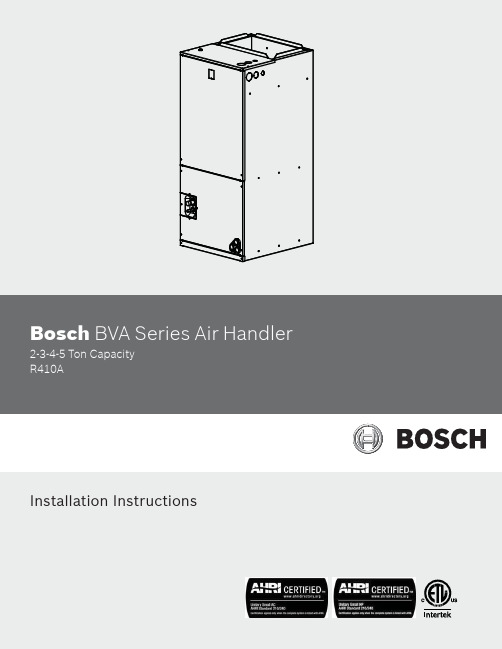
Bosch BVA Series Air Handler 2-3-4-5 Ton CapacityR410AInstallation InstructionsData subject to change06.2016 | Bosch Thermotechnology Corp.Table of Contents1 Key to symbols and safety instructions 42 General 63 Applications 84 Electrical wiring 105 Airfl ow performance 126 Ductwork 137 Refrigerant connections 148 Air fi lter (not factory-installed) 149 Filter installation dimensions 1510 Wiring diagram 1611 Spare parts 19Bosch Thermotechnology Corp. | 06.2016 Data subject to change06.2016 | Bosch Thermotechnology Corp.Data subject to change 1 Key to symbols and safety instructions1.1 Key to symbolsWarningsThe following keywords are defi ned and can be used in this document: ④DANGER indicates a hazardous situation which, if not avoided, will resultin death or serious injury.④WARNING indicates a hazardous situation which, if not avoided, could result in death or serious injury.④CAUTION indicates a hazardous situation which, if not avoided, could result in minor to moderate injury.④NOTICE is used to address practices not related to personal injury.Important information1.2 SafetyPlease read before proceedingThis document is customer property and is to remain with this unit.These instructions do not cover all the diff erent variations of systems nor does it provide for every possible contingency to be met in connection with installation.Bosch Thermotechnology Corp. | 06.2016Data subject to change06.2016 | Bosch Thermotechnology Corp.Data subject to change 2 GeneralThe unit can be positioned for bottom air return in the upfl ow position, left and right return in the horizontal position, top return in downfl ow position. This Air Handler provides the fl exibility for installation in any upfl ow , downfl ow or horizontal application. Adjust motor speed tap through DIP switch to select correct air fl ow according to blower performance table.Top and side power and control wiring, accessible screw terminals for control wiring all combine to make the installation easy, and minimize installation cost. See fi g.3.To ensure the proper installation, select a solid and level site. Ensure enough space is maintained for installation and maintenance.2.1 Unit dimensionsFigure 3Table 1Bosch Thermotechnology Corp. | 06.2016 Data subject to change06.2016 | Bosch Thermotechnology Corp.Data subject to change3 Applications3.1 Vertical up fl ow④Vertical Upflow configuration is the factory default on all models (see Fig 3).④If return air is to be ducted, install duct flush with floor. Use fireproofresilient gasket 1/8 to 1/4 in. thick between the ducts, unit and floor. Set unit on floor over opening.Lightly tighten the drain connections so they do not leak. Using excessiveforce may/will cause damage to the unit.(see Fig.3&4)3.2 Vertical down fl owConversion to Vertical Down fl ow:A vertical upfl ow unit may be converted to vertical downfl ow. Remove the door and indoor coil and reinstall 180° from original position. See Fig 5.To comply with Safety Standars and the National Electric Code for downfl ow application, the circuit breaker(s) on fi eld installed electric heater kits refer to electric heater kit installation manual for more detail. The breaker switch “on” position and marking are up and, “off ” position and marking are down.3.3 HorizontalHorizontal right is the default factory confi guration for the units. Conversion to Horizontal left: A vertical upfl ow unit may be converted to horizontal left by removing indoor coil assembly and reinstalling coil as shown for left hand air supply.④Rotate the unit 90° into the horizontal left position, with the coilcompartment on the right and the blower compartment on the left. See Fig. 5.④Reinstall the indoor coil 180° from original position. Ensure the retaining channel is fully engaged with the coil rail. See Fig. 5.④Secondary drain pan kits are recommended when the unit is configured for the horizontal position over a finished ceiling and/or living space.3.4 Installation in an unconditioned spaceThere are two pairs of coil rails in the air handler for default and counterfl ow application. If the air handler is installed in an unconditioned space,the two unused coil rails should be removed to minimize air handlersurface sweating. The coil rails can be easily removed by taking off the 6mounting screws from both sides of the cabinet.Bosch Thermotechnology Corp. | 06.2016 Data subject to change06.2016 | Bosch Thermotechnology Corp.Data subject to change 4 Electrical wiringField wiring must comply with the National Electric Code (C.E.C. in Canada) and any applicable local ordinance.4.1 Power wiringIt is important that proper electrical power is available for connection to the unit being installed. See the unit nameplate, wiring diagram and electrical data in the installation instructions.④If required, install a branch circuit disconnect of adequate size, located within sight of, and readily accessible from the unit.When the Electric Heater is installed, units may be equipped with one or two 30-60 amp. circuit breakers. These breaker(s) protect the internal wiring in the event of a short circuit and serve as a disconnect. Circuit breakers installed within the unit do not provide over-current protection of the supply wiring and therefore may be sized larger than the branch circuit protection.④Supply circuit power wiring must be 75°C minimum copper conductors only. See Electrical Data In this section for ampacity, wire size and circuit protector requirement. Supply circuit protective devices may be either fuses or “HACR” type circuit breakers.4.2 Control wiringClass 2 low voltage control wiring should not be run in conduit with main power wiring and must be separated from power wiring, unless class 1 wire of proper voltage rating is used.④Low voltage control wiring should be 18 Awg. color-coded. For lengths longer than 100 ft., 16 Awg. wire should be used.④Low voltage control connections are made to low voltage pigtails within air handler control box.④See wiring diagrams attached to indoor and outdoor sections to be connected.④Make sure, after installation, separation of control wiring and power wiring has been maintained.4.3 Grounding④Grounding may be accomplished by grounding metal conduit when installed in accordance with electrical codes to the unit cabinet.④Grounding may also be accomplished by attaching ground wire(s) to ground lug(s) provided in the unit wiring compartment.④Use of multiple supply circuits require grounding of each circuit to lug(s) provided in unit.4.4 Electrical dataTable 24.5 Electrical kit MCA/MOP dataTable 3Heat kit suitable for AHU multi position installation.[ ● means available, X means not available, * means single circuit ]Heater Kit AccessoriesTable 4[ ● means available, X means not available ]Bosch Thermotechnology Corp. | 06.2016 Data subject to change06.2016 | Bosch Thermotechnology Corp.Data subject to change 5 Air fl ow performanceAirfl ow performance data is based on cooling performance with a coil and no fi lter in place. Check the performance table for appropriate unit size selection. External static pressure should stay within the minimum and maximum limits shown in the table below in order to ensure proper operation of both cooling, heating, and electricheating operation.Table 5- Bold outlined areas represent airfl ow outside of the required 300-450 cfm/ton range.SCFM means Standard Cubic Foot per Minute.Airfl ow based upon Air Handler Unit operating at 230V with no electricheater kit and no fi lter. Airfl ow at 208V is approximately the same as 230V.Bosch Thermotechnology Corp. | 06.2016Data subject to changeThe air distribution system has the greatest eff ect on airfl ow. The duct system is totally controlled by the contractor. For this reason, the contractor should use only industry-recognized procedures.Heat pump systems require a specifi ed airfl ow. Each ton of cooling requires between 350 and 450 cubic feet of air per minute (CFM), or 400 CFM nominally.Duct design and construction should be carefully done. System performance can be lowered dramatically through bad planning or workmanship.Air supply diff users must be selected and located carefully. They must be sized and positoined to deliver treated air along the perimerter of the space. If they are too small for their intended airfl ow, they become noisy. If they are not located properly, they cause drafts. Return air grilles must be properly sized to carry air back to the blower. If they are too small, they also cause noise.The installers should balance the air distribution system to ensure proper quiet airfl ow to all rooms in the home. This ensures a comfortable living space.An air velocity meter or airfl ow hood can be used to balance and verify branch and system airfl ow (CFM).6 DuctworkField ductwork must comply with the National Fire Protection Association NFPA 90A,NFPA 90B and any applicable local ordinance.Sheet metal ductwork run in unconditioned spaces must be insulated and covered with a vapor barrier. Fibrous ductwork may be used if constructed and installed in accordance with SMACNA Construction Standard on Fibrous Glass Ducts. Ductwork must comply with National Fire Protection Association as tested by U/L Standard 181 for Class I Air Ducts. Check local codes for requirements on ductwork and insulation.④Duct system must be designed within the range of external static pressure the unit is designed to operate against. It is important that the system airflow be adequate. Make sure supply and return ductwork, grills, special filters, accessories, etc. are accounted for in total resistance. See airflow performance tables in this manual.④Design the duct system in accordance with “ACCA” Manual “D” Design for Residential Winter and Summer Air Conditioning and Equipment Selection.Latest editions are available from: “ACCA” Air Conditioning Contractors of America, 1513 16th Street, N.W., Washington, D.C. 20036. If duct system incorporates flexible air duct, be sure pressure drop Information (straight length plus all turns) shown in “ACCA” Manual “D” is accounted for in system.④Supply plenum should be attached to the 3/4” duct flanges supplied with the unit. Attach flanges around the blower outlet.The front flange on the return duct if connected to the blower casing must not be screwed into the area where the power wiring is located. Drills or sharp screw points can damage insulation on wires located inside unit.④Secure the supply and return ductwork to the unit flanges, using proper fasteners for the type of duct used and tape the duct-to-unit joint as required to prevent air leaks.06.2016 | Bosch Thermotechnology Corp.Data subject to change 7 Refrigerant connectionsKeep the coil connections sealed until refrigerant connections are made. See the Installation Instructions for the outdoor unit for details on line sizing, tubing installation, and charging information.Coil is shipped fi lled with Nitrogen. Evacuate the system before charging with refrigerant.Install refrigerant lines so that it does not block service access to the front of the unit.Nitrogen should fl ow through the refrigerant lines while e a wet rag or an approved heat paste to protect the TXV sensing bulb during the brazing process.After the refrigerant line connections are made, seal the gap around the connections with pressure sensitive gasket.7.1 Condensate drain connectionConsult local codes for specifi c requirements.1. When making drain fi tting connections to the drain pan, use a thin layerof Tefl on paste, silicone or Tefl on tape and install, hand tighten.2. When making drain fi tting connections to drain pan, do not overtighten Over tightening fi ttings can split pipe connetions on the drain pan.④Install drain lines so they do not block service access to front of the unit.Minimum clearance of 24 inches is required for filter, coil or blower removal and service access.④Make sure unit is leveled or pitched slightly toward primary drain connection so that water will drain completely from the pan. (See Fig. 7)④Do not reduce drain line size to less than connection size provided on condensate drain pan.④All horizontal drain lines must be pitched downward away from the unit a minimum of 1/8” per foot of line to ensure proper drainage.④Do not connect condensate drain line to a closed or open sewer pipe. Run condensate to an open drain or run line to a safe outdoor area.④The drain line should be insulated where necessary to prevent sweating and damage due to condensate forming on the outside surface of the line.④Make provisions for disconnecting and cleaning of the primary drain line should it become necessary. Install a 3 inch trap in the primary drain line as close to the unit as possible. Make sure that the top of the trap is below connection to the drain pan to allow complete drainage of pan (See Fig. 7).④Auxiliary drain line should be run to a place where condensate will be noticeable. Homeowner should be warned that a problem exists if water should begin running from the auxiliary drain line.④Plug the unused drain connection with the plugs provided in the parts bag, using a thin layer of teflon paste, silicone or teflon tape to form a water tight seal.④Test condensate drain pan and drain line after installation is complete. Pour water into drain pan, enough to fill drain trap and line. Check to make sure drain pan is draining completely, no leaks are found in drain line fittings, and water is draining from the termination of the primary drain line.8 Air fi lter (not factory-installed)An external fi lter or other means of fi ltration must be properly sized for a maximum of 300 feet/min. air velocity or what is recommended for the type fi lter installed.Filter application and placement are critical to airfl ow, which may aff ect the heating and cooling system performance. Reduced airfl ow can shorten the life of thesystem’s major components, such as motor, elements, heat relays, evaporator coil or compressor. Consequently, we recommend that the return air duct system have only one fi lter location. For systems without a return air fi lter grill, multiple fi lter grills can be installed at each of the return air openings.If adding high effi ciency fi lters or electronic air fi ltration systems, it is very important that the air fl ow is not reduced. If air fl ow is reduced the overall performance and effi ciency of the unit will be reduced. It is strongly recommended that a professional installation technician is contacted to ensure such fi ltration systems are installed correctly.Do not double fi lter the return air duct system. Do not fi lter the supply airduct system. This will change the performance of the unit and reduce airfl ow.9 Filter installation dimensionsDimensional dataTable 6Air fi lter removal / installation④Remove bolts manually, remove air filter cover, see Fig. 6;④Hold the edge of the air filter and extract out .④Install new filter so that the arrow on the filter is in the same direction asairflow.Bosch Thermotechnology Corp. | 06.2016 Data subject to change06.2016 | Bosch Thermotechnology Corp.Data subject to change 10 Wiring diagram④To avoid the electrical shock, please please ensure the air conditioner is properly grounded. The main power plug in the air conditioner has been joined with the ground wiring, please do not alter.④Do not strain the power wiring.④When connecting the air conditioner with the ground, observe the local codes.④If necessary, connect wiring to the power fuse or circuit breaker.Electric wiring gauge for H/P systemsTable 7If indoor unit has auxiliary heating already installed and a diff erent auxiliary heating unit is required, the indoor unit (A) and indoor line diameters will be diff erent.For ECM Motor (Size 24/48K)For ECM Motor (Size 36/60K)Bosch Thermotechnology Corp. | 06.2016 Data subject to change06.2016 | Bosch Thermotechnology Corp.Data subject to changeUnit WiringFigure 1211 Spare partsBosch Thermotechnology Corp. | 06.2016 Data subject to changeUnited States and CanadaBosch Thermotechnology Corp. 50 Wentworth Avenue Londonderry, NH 03053Tel: 866-305-9974Fax: 603-965-7581BTC 761701101 C / 06.2016。
净水机安装方法

净水器纯水机安装方法安装:一、安装开始前要先弄清楚用户水源是市政自来水还是地下净水或是其它类型水源:✧ 市政自来水:检测水压,纯净水机产品标准适用0.1-0.3兆帕,水压过高(0.4MPA以上)建议用户加装减压阀;水压过低(0.1MPA以下)建议用户加装增压泵等装置或直接推荐用户使用有自吸功能的产品。
✧ 地下水:由于地下水泥沙含量较大或硬度高,一般需要要求用户加装预处理系统(一般为PPF、折叠滤芯、超滤膜或软化装置),使用地下水的用户一般会使用无塔供水装置或水塔的方式供水,使用水塔供水装置的用户要注意,水塔高度距离用水点最少要有10米(大约两层楼房高度),否则就要建议加装管道泵或是改为无塔供水装置。
二、安装开始时有需要向用户收取费用的情况时要事先明确提醒用户,先考虑产品的安装或放置地点,链接管路走向等根据用户的实际情况(或根据用户要求)给用户设计一个合理的安装布局做到心中有数以后再开始进行安装工作。
✧ 首先进行产品组装工作,工作流程为→安装压力桶球阀→安装RO膜→安装前三级预处理滤芯;✧ 随后安装进水三通(安装时要注意辨别冷热水管;进水球阀扳手的朝向要以能够方便的进行开关操作为准)✧ 接着安装鹅颈龙头(在水盆上安装时要注意选择安装位置,要以鹅颈龙头接管时能够下得去手方便的连接管线为准,不锈钢水盆打孔时要尽量让手电钻的转速在最慢的状态进行以免烧坏钻头开孔器。
)✧ 将主机和压力桶放置到预定地点(以以后能够方便的更换滤芯或进行维修为准)✧ 最后连接管线(一般4条管线长度要以能够将主机放置到橱柜柜门外能够进行维修为准,管线要先连接进水管路,同时打开进水阀门;随后依次连接压力桶→水龙头→废水管)✧ 检测高低压开关工作状态(具体操作方法是:关闭进水阀门机器停机,打开进水阀门机器启动则低压开关工作正常;同时关闭水龙头和压力桶球阀机器停机,打开水龙头或压力桶球阀机器启动则高压开关正常)✧ 随后试运行30分钟,检测有无漏水现象,检测出水TDS值是否达到标准(以TDS值50PPM内或RO膜去除率95%为准)✧ 最后使用扎条将废水管出水端固定,其他管路也要走得美观一些三、安装完成后认证会同用户填写《安装维修单》、《保修卡》、《重要提示》等单据,并请用户签字确认,最后拨打电话到公司对用户进行业务回访。
纯水机安装方法

纯水机安装方法纯水机安装的具体方法有以下几步:一:选择安装位置纯水机安装-位置的基本要求:1、机器就近水源安装,排水要方便2、机器安装位置不会影响到用户的其他日常操作3、机器及管路安装在不会受到阳光直射的地方4、尽可能安装在有排水地漏等设施的地方,比如厨房间,卫生间,避免安装在有木质地板或有贵重物品的附近二:在选定的主机安装位置用记号笔做好记号,用电锤打孔,将挂板纯水机安装的具体方法有以下几步:一:选择安装位置纯水机安装-位置的基本要求:1、机器就近水源安装,排水要方便2、机器安装位置不会影响到用户的其他日常操作3、机器及管路安装在不会受到阳光直射的地方4、尽可能安装在有排水地漏等设施的地方,比如厨房间,卫生间,避免安装在有木质地板或有贵重物品的附近二:在选定的主机安装位置用记号笔做好记号,用电锤打孔,将挂板用膨胀螺丝固定到墙面上。
(厨下安装此步骤可省略)A、挂板孔要水平,不能有肉眼能察觉的歪斜现象B、挂板螺丝必须拧紧,能承受机器的重量三:将制水主机的面盖打开(指箱式机),将制水主机挂到挂板上。
(厨下安装时等鹅颈龙头安装完毕后将制水主机放到橱柜外方便操作的位置)四:纯水机安装-预处理滤芯(指厨下裸机)将随机配的预处理滤芯按PP-颗粒活性炭-炭棒的顺序安装A、注意滤芯的先后顺序B、颗粒活性炭带密封圈的一端朝上C、拧紧滤瓶时注意:先轻轻晃动滤瓶感觉无阻力时(此时滤芯完全与滤瓶中心定位孔及出水口对齐)方可彻底拧紧,防止滤芯不居中导致内漏D、拧紧滤瓶时要注意O形圈不要损伤,若O形圈容易掉,请给O形圈摸少许凡士林五:纯水机安装-进水三通及进水小球阀:1、根据用户的实际情况,关闭用户的总进水阀或橱柜里面的角阀,打开用户的水龙头将管道里面的压力卸掉;2、根据实际安装位置,旋下用户的水龙头或橱柜里面的冷水连接软管,将随机配的进水三通外螺纹处缠好生料带,连接到自来水管路上;将进水小球阀外螺纹处缠好生料带,连接到进水三通侧面的内螺纹处;将自来水龙头或连接软管装回;3、将进水小球阀关闭,打开自来水总阀或橱柜下面的角阀,对刚安装的进水三通进行试漏,检查有无漏水或渗水现象。
安装说明书
3. 安装步骤示意图......................................................................................................................................................... 18
7.1. 抽真空 .................................................................................................................................................................. 25 7.2. 追加制冷剂 .......................................................................................................................................................... 25
9. 试运行......................................................................................................................................................................... 28
Rainman水制器安装指南说明书

Although the Rainman watermaker is designed as a portable system not requiring installation, many of our customers choose to partially or fully install the system in their boat. The variations can range widely, including installation of both the pressure supply unit and reverse osmosis case to installing one or the other of the units. An install process should be undertaken by a skilled and experienced technician. As such, this is not a comprehensive guide but a document of tips and issues for consideration.Pressure Supply Unit:•If taking water in from through hull, ensure a sea strainer is in place to catch coarse matter prior to getting in to pre-filter assembly.•Ensure through hull location will not let air into the system. Account for healing of sailing vessel and avoid through hull too near the bow.•Mount pressure supply unit in a cool dry location.•Ensure you leave access to easily view and change the pre-filter.•Intake hose should be minimum of 1/2” diameter.•Pressure supply unit has in built lift pump. Do not exceed 2 metres (6 ft) above the water line. •We recommend not installing any petrol powered device in an enclosed area.• A 10 litre (2.5 gallon) bucket should be used and accessible through a T valve for fresh water rinsing and membrane pickling purposes. Vessel tank water should not be used for fresh water rinsing or membrane pickling as there may be residual chlorine in the tank from previous filling with city water. This chlorine will damage your reverse osmosis membrane.•If you wish to draw water from the vessel tank for fresh water rinsing, an inline active carbon filter can remove the residual chlorine.• A dedicated through hull is best. If shared with other appliances, it is critical to ensure your Rainman watermaker is not being starved of feed water by competing with other appliances. Reverse Osmosis Case:•The brine output should be above the water line to avoid back pressure. Use the easiest method to dump brine overboard, including internal sinks, etc.•The product water hose should have T valve for water tasting/testing, fresh water flushing, and membrane pickling.•The product water hose should feed into top of vessel tank to avoid back pressure.•There is practically no limit on length of high pressure hose, product water hose, or brine outputhose.•The reverse osmosis pressure vessel housings may be mounted within the Rainman case orremoved and mounted on their own.。
产品技术手册A

产品技术手册第一部分、什么是艾尔柯家居环境智能集成?艾尔柯家居环境智能集成即Smart Home & EnvironmentIntegration,主要包括环境集成和智能集成。
一、艾尔柯家居环境集成要求温度:衡量空气冷、热程度的指标;一般卧室夏天高标准温度24℃-26℃,冬天18℃-21℃、儿童房、老人房温度夏天高标准温度25℃-27℃,冬天20℃-23℃、卫生间夏天高标准温度24℃-26℃,冬天23℃-25℃。
湿度:指空气相对湿度即空气中所含水蒸气的比例指标;空气温度升高时,湿度则会降低,一般卧室夏天湿度≤60%RH,冬天≥40%RH、书房夏天湿度≤55%RH,冬天≥40%RH、儿童房、老人房夏天湿度≤55%RH,冬天≥40%RH。
空气的洁净度:衡量空气清洁程度的指标;浮尘量≤0.15mg/㎥一氧化碳≤10PPM 二氧化碳≤800PPM、无灰尘、人及宠物的皮屑、过量湿气、烟气、各种异味、虫螨等过敏源,各类病菌、二氧化碳(Voc 甲醛苯氢气等)。
噪音:发生体做无规则振动时发出的声音,是一类引起人烦躁、或音量过强而危害人体健康的声音;研究表明,30分贝以下属于非常安静的环境,如播音室、医院等应该满足这个条件。
40分贝是正常的环境,如一般办公室应保持这种水平。
风速:衡量中央空调室内机送风速度的指标,夏季≤0.3 m/s,冬季≤0.2m/s。
新风量:衡量从室外引进新鲜空气的指标;一般无吸烟卧室新风量高标准35l/s、有吸烟的客厅新风量高标准30l/s、餐厅新风量高标准35l/s、吸烟的书房新风量高标准50l/s。
高品质的水:1、净水:水中无余氯、异色异味、藻类及其固体悬浮物、无铁、金属离子、氢硫化物、无细菌、无有机化学物质2、软水:中国标准软水Less than 50毫克/升、美国标准软水Less than 17.0毫克/升3、直饮有氧健康水。
二、艾尔柯家居环境智能集成生活六化的要求人性化:家居环境产品的设计“以人为本”,充分考虑使用者的年龄、层次、生活习惯、爱好、嗜好和极好的生活便利性。
水轮发电机水力机械辅助设备安装作业指导书
水轮发电机水力机械辅助设备安装作业指导书水轮发电机水力机械辅助设备安装作业指导书二零零七年月日实施(一)电站概况朝阳水电站位于云南省保山市境内,为苏帕河干流规划五级电站的第二级,电站装机容量40MW。
朝阳水电站为引水式电站,工程由首部枢纽及引水发电系统组成。
厂区枢纽主要建筑物有:主副厂房、尾水渠、升压站等。
各建筑物沿苏帕河顺河布置。
主厂房由主机间和安装间组成,主机间尺寸为28、7m×15、9m×25、35m(长×宽×高),安装间布置在主厂房左端,尺寸为11、6m×15、9m×19、65m(长×宽×高)。
副厂房由上游副厂房和端部副厂房组成,上游副厂房尺寸28、7m×6、8m×14、75m(长×宽×高),端部副厂房尺寸22、12m×10m×10、1m(长×宽×高)。
地面式升压站平面尺寸69、5m×58、4m,布置在主厂房右端。
(二)施工总则1、认真熟悉制造厂家的随机文件和设计图纸,按照《水轮发电机组安装技术规范》(GB8564—88)要求进行组织施工。
2、根据制造厂家的随机文件和设计图纸与有关技术规范进行水轮机及其辅助设备,以及电气设备的安装、调整、试验。
3、凡制造厂家的说明书与其他技术文件未作明确规定和要求时,应同厂家、监理及业主协商确定。
4、作好各项安装、调整、试验记录,并报监理认可。
5、尊重甲方、设计和监理人员,在施工中发现问题,应及时进行沟通,征得他们同意后方可进行工作。
6、遵守国家的安全规章条令,制定安全施工措施,保护工程现场安全,维护工地的生产、生活秩序正常进展。
7、教育施工人员遵守国家的环境保护法令,保持好施工区和生活区的环境卫生,减少对环境的污染和流行疾病的发生。
(三)工程特点发电厂房布置在苏帕河左岸,发电机层地面高程1452、85米。
家用纯水机安装流程

家用纯水机安装流程
第一步、折箱检验配置是否完整
1
配件包
2
主机箱
3
前置滤筒箱(注箱体纯水机无)
4
压力桶
配件箱清单
• 直饮纯水龙头及连接配件一包 • 四化二 三通球阀及连接配件一包 • 使用说明书及安装单一包 • 反渗透RO膜一个 • 拆装扳手一大一小各一把(注箱体机只有小的
) • 镙丝配件包一包和龙头挂片一个
2、纯水机出水并运行稳定(约5~10分钟),检查纯水机的各接头连接 是否可靠,膜壳、滤芯等接口处有无漏水现象。
3、关闭纯水鹅颈龙头和压力桶球阀,等待约30秒,检查直饮纯水机废水 是否停止。
4、打开鹅颈龙头,观察龙头是否有纯水流出,如无纯水流出,检查是否 因为自来水水压过低或高压开关不能复位。
5、机器处于工作状态,关闭进水球阀,一段时间后观察机器是否停止工 作,如不停机,检查低压开关是否不能复位。
进水三通的连接方法
首先关闭进水阀门,将 进水阀门上金属软管拧 下。取出直饮纯水机配 件盒中进水三通,将进 水三通内螺纹的一端拧 在进水阀门出水口上; 将刚拧下的金属软管一 端拧在进水三通外螺纹 上。
第四步、安装反渗透RO膜
首先将纯水机主机从包装箱内取出,打开纯水机的外罩或外壳,将膜壳 盖进水端接头上的螺帽拧下,取出进水管,然后用膜壳扳手将膜壳盖拧 开,再将反渗透膜从真空包装袋中取出,将有两个0型圈一端朝里装入 反渗透膜壳中并塞紧,最后将膜壳盖拧上,并用膜壳扳手将膜壳盖拧紧, 进水管接回膜壳进水接头上,并拧紧螺帽,将膜壳卡入大单夹内,装上 纯水机的外罩或外壳。
纯水机工作流程图
纯水机控制电路图示
Байду номын сангаас
③新安装的颗粒活性碳滤芯、后置活性碳滤芯,必 须待活性碳粉屑排尽后方可接回其后的管路,进 行制水。
纯水机安装工作流程课件

滤芯安装问题
总结词
滤芯安装不当或破坏
详细描述
滤芯是纯水机的核心部件,如果安装不当或使用 过期滤芯,会影响净水效果。
解决方案
按照厂家提供的说明书正确安装滤芯,并定期更 换合格滤芯,确保净水效果。
水龙头安装问题
总结词
水龙头安装不稳固或漏水
详细描述
水龙头是纯水机的重要出水口,如果安装不规范或密封不良,会导 致漏水或松动。
。
连接电源及调试
连接电源
将纯水机的电源线连接到合适的电源插座上 ,确保连接坚固。
调试
根据需要调整纯水机的各项参数,如出水流 量、水质等,确保满足家庭用水需求。
开机测试
打开纯水机的开关,视察机器是否正常工作 ,如有问题应及时断电检查。
定期维护
按照说明书要求定期对纯水机进行维护保养 ,保证其正常运转和延长使用寿命。
在开始安装前,确保所有配件齐全且无破 坏。
选择合适的位置进行安装,确保纯水机能 够稳定运行,同时便于日后的维护和保养 。
遵循安装指南
检查安装后的密封性
严格按照安装指南进行操作,确保每一步 的正确性。
确保接口处密封良好,无渗漏现象,以保 证纯水机的正常运作。
使用规范注意事项
定期清洗和维护
为保证纯水机的性能和使用寿命,需定期进行清 洗和维护。
安全注意事项
断电操作
在安装过程中,确保电源已关闭,以 防止触电事故。
防滑措施
在操作平台上铺设防滑垫,防止安装 人员滑倒。
佩戴防护眼镜
在操作过程中,为防止溅水或碎屑飞 溅,需佩戴防护眼镜。
遵循操作顺序
按照规定的操作顺序进行安装,避免 因操作不当引发安全事故。
安装质量注意事项
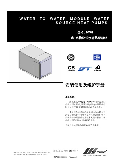
MWH水水模块式水源热泵(冷水)机组安装使用说明书090414
1、特点 (3)2、总则 (3)3、外形尺寸 (4)4、基础图 (5)5、安装要求 (6)6、操作 (9)7、维护与保养 (11)8、附图 (14)一.采用涡旋压缩机的水-水热泵机组:1.1超高能效,能效比比目前市场上最先进的活塞压缩机还高12%。
1.2接近100%的容积效率可带来高的制冷能力。
1.3随着涡旋盘的逐渐磨合,机组性能将逐渐提高。
1.4全自动电脑控制,无须专人管理。
1.5模块化组合,安装方便。
1.6采用四通阀直接切换,减少大量的水路切换成本。
1.7外形美观大方,体积小,适用于别墅、宾馆、饭店、船舶及其他小于3000M2的中小型建筑等。
2.1机组的辨认机组运抵现场后,应确认机组是否符合订货要求及对装箱资料进行对照验证。
2.2机组检查机组还未搬离运输设备时,应进行仔细的检查。
如果机组在运输过程中被损坏,应由押运设备的检查员来检查并提出赔偿要求,并通知美意销售部。
厂方对运输过程中造成的损坏不负任何责任。
未经美意销售部的许可,不得安装损坏的机组。
2.3机组简介MWH型机组是单级压缩、适应安装在室内的机组,每台机组都是完全密封组装的,即装运前由厂方配管、布线,做气密性试验,充灌制冷剂,并经正式的控制操作试验。
MWH020/025/030/035:D E T A I L A4-2"MWH040/050/060:MWH070/080/090:MWH020余热回收MWH020/025/030/035:6底脚螺栓预埋孔; 垫上400X 150X 10的橡胶减震垫; 3、图示100X 100槽为排水沟,对于排水顺畅处可不设;4、本基础为混泥土结构。
A-A安装基础图(仅供参考)MWH040/050/060:MWH 040/050/060安装基础技术要求: 1、未注尺寸公差按G B /T 1804-C ; 2、预埋螺栓为M16; 3、机组安装时应垫上400X 150X 10的橡胶垫,用作减震.S E C T IO N A -AMWH070/080/090:MWH 080安装基础技术要求:1、未注尺寸公差按G B /T 1804-C ;2、预埋螺栓为M16;3、机组安装时应垫上400X 150X 10的橡胶垫,用作减震.S E C T I O N A -A5.1防噪音措施机组应安装在远离噪声敏感区,将隔震垫放在机组支架下面(具体见机组安装)。
全自动软化水设备使用说明及安装注意事项.doc
全自动软化水设备使用说明及安装注意事项软化水设备简要说明:软化水设备就是采用阳树脂对水进行软化,主要目的是让阳树脂吸附水中的钙、镁离子(形成水垢的主要成分)、降低水的硬度,并可以进行树脂再生,循环使用。
全自动软水器是将软化器运行及再生的每一个步骤实现自动控制,并采用时间、流量或其它感应器等方式来启动再生。
全自动软水器的基本构成为:多路控制阀、树脂罐(含树脂)、盐箱及管路系统。
软水器采用强酸性阳离子树脂将原水中的钙、镁离子置换出去,经该设备流出的水而为硬度极低的软化水。
其化学反应为:2RNa+Ca2+(Mg2)=R2Ca(Mg)+2Na+。
当树脂吸附到一定量的钙、镁离子后必须进行再生-用饱和盐水浸泡树脂把树脂里的钙、镁离子等硬度置换出来,恢复树脂的软化交换能力,并将废液排出。
其化学反应为:R2Ga=2RNa+Ca2+ 。
整个再生过程包括:反洗-松动树脂层,吸盐慢洗-发生交换反应,冲洗(正洗)-将化学反应交换下来的钙、镁离子冲净,注水-为了下次再生。
全自动软化水设备选型软化水设备的选型主要依据是需水量、原水硬度及适用场合1) 相同出水量的设备有多种型号,可根据实际用水情况选取。
2) 原水硬度:原水硬度≤3m·mol/L时,可以选时间控制型,按设备最大产水量计;原水硬度≤6m·mol/L时,可以按表中设备的最大产水能力选型;原水硬度≤8m·mol/L时,可按设备产水能力的平均值选型;原水硬度8~10m·mol/L,应按设备最小产水能力计算,或采用多级系统;原水硬度≥10m·mol/L,须选用多级处理,一般两级处理可达到要求。
3) 用水场合:如果配用热水锅炉或其他同类设备,可按设备最高产水能力选型; 如果向蒸汽锅炉供水,一般按锅炉蒸发量的1.2倍与设备产水能力匹配。
软化水设备主要技术指标:1.进水压力:0.2~0.5Mpa2.原水硬度:<12mmol/L(当原水硬度>8 mmol/L时,应事先声明)3.出水硬度:<0.03mmol/L (达到《国家低压锅炉水质标准》GB1576-2001要求);4.原水含盐量<1000mg/L,浊度<55.电源:~220V,50HZ6.盐耗量<100g/克当量(与原水硬度有关);7.水耗<2%;电耗<40W软化水设备特点1.选用高性能离子交换树脂,工作交换容量大,能耗低,使用寿命最长。
饮水机装配工艺流程
饮水机装配工艺流程下载温馨提示:该文档是我店铺精心编制而成,希望大家下载以后,能够帮助大家解决实际的问题。
文档下载后可定制随意修改,请根据实际需要进行相应的调整和使用,谢谢!并且,本店铺为大家提供各种各样类型的实用资料,如教育随笔、日记赏析、句子摘抄、古诗大全、经典美文、话题作文、工作总结、词语解析、文案摘录、其他资料等等,如想了解不同资料格式和写法,敬请关注!Download tips: This document is carefully compiled by theeditor. I hope that after you download them,they can help yousolve practical problems. The document can be customized andmodified after downloading,please adjust and use it according toactual needs, thank you!In addition, our shop provides you with various types ofpractical materials,such as educational essays, diaryappreciation,sentence excerpts,ancient poems,classic articles,topic composition,work summary,word parsing,copy excerpts,other materials and so on,want to know different data formats andwriting methods,please pay attention!饮水机装配工艺流程饮水机是现代办公室、学校等公共场所必备的设备之一,其装配工艺流程也是需要注意的。
纯水机安装步骤及注意事项

纯水机安装步骤及注意事项第一篇:纯水机安装步骤及注意事项纯水机安装:安装步骤和注意事项纯水机安装:安装步骤和注意事项一、开箱检查零部件是否齐全(见纯水机安装:附件配置表)二、安装进水三通球阀(见纯水机安装:和进水三通.球阀)三、连接管线,安装纯水龙头和排水管线(见纯水机安装:安装示意图)四、安装RO膜(见纯水机安装:RO膜的安装)五、通水、通电1、打开连接纯水机的自来水阀门(装有进水三通和球阀的还需要打开球阀).2、接通电源.3、此时纯水机应该开始自动工作,其特征是纯水机的隔膜泵会有轻微振动,同时排水管开始短促排放废水.纯水机制作一桶纯水的时间:3加伦桶(LH7-1M/LH7-1K)大约为50-60分钟,六、使用前的注意事项1、纯水机在初次使用时,第一次放出的纯水中会有气体和少量碳粉,这属于正常现象,只需要连续的开闭几次纯水龙头,一般来说大约将纯水机储水桶的需前两桶水排放掉,就会把气体和碳粉排放干净,2、纯水的质量可以由测定纯水的TDS(溶解性总固体)并计算脱盐率来检查.使用的测试工具为TDS测试笔.指出以上出现的一个问题,一般50-75加仑膜,制满一桶水需耗时90分钟,计算方法如: 50加仑/24h*3.785L/加仑=7.89L/H3.2加仑压力桶的制水时间为:3.2加仑*3.785L/加仑/7.89L/H=1.5L,约合90分钟;当然制水耗时也随温度变化,冬天温度低,自然耗时要长,夏天耗时稍短.安装流程:步骤:第一步:穿好鞋套进入客户家中,勘察安装地点(水源、电源、龙头是否好装),现场铺上事先准备好的报纸或纸盒;第二步:打开机箱,检查随机配件:1、机头(盒子).2、滤瓶+滤芯(盒子).3、压力桶(盒子).4、鹅颈笼头(盒子).5、RO膜.6、配件包(进水三通、2分球阀、压力桶球阀、鹅颈吊片、白螺帽各一样,管塞6个).7、说明书.8、合格证.9、保修卡.10、10寸扳手一把.11、2分水管5米.第三步: 安装RO膜:拆开包装,打开RO膜壳盖,小头向内,RO膜壳丝口要涂甘油润滑,防止漏水;第四步: 按顺序安装前三道滤芯;1、第一节:10寸5umPPF2、第二节:10寸85C(注:箭头朝上)3、第三节:10寸1umPPF第五步:安装压力桶球阀(关闭状态):螺丝口18--22圈生料带,掌握力度,不可用力过大.第六步:接进水:A)接冷水管:2分球阀(约20圈生料带).B)接三通:20--30圈生料带.第七步: 安装鹅颈龙头:先打好眼,配件包里按照垫片的大小顺序,分清台面以上的部分和台面以下的部分,最重要的是留意空心球,不要丢失,最后以厨门的边为距离,连接T33左侧的4044接口(绿色).第八步:接压力桶:连接T33右侧的7544接口(黄色).第九步:连接废水口:用废弃的转用螺丝刀,加热后在下水管道上烫一个洞,把废水管插入10公分以上,接着用扎带固定废水管,再用703胶密封,最后连接废水比后面的7544接口(黑色).第十步:电源插口:直接插上即可;如没有电源,那么需要寻找就近的地方,接长电线,从橱柜内部开孔钻眼,保持装修的完整性;第十一步: 调试:A)断开前置过滤器的第二节和第三节过滤筒的连接处,让活性碳黑水流出3—5分钟,直至出水变清为止.B)关闭压力桶球阀,打开鹅颈笼头,通电通水.1分30秒的自动冲洗后,开始造水(放水冲洗20分钟);第十二步: 填写保修卡,向客户交代使用及注意事项:A)第一次使用,需要放空两桶水,以冲洗活性碳的残余物质,机器每制水一桶时间为1个半小时,从安装工出门开始算起,每隔一个半小时放掉一桶水,第三桶水即可饮用,如当日无时间,晚上或第二日清晨操作也可以;B)客户家中超过两日无人在家时,请关闭水源和电源;C)如遇到机器故障,如漏水,请先关闭水源和电源,再播打报修电话;第十三步: 合理布置水管和电线,保持美观整洁.第十四步: 打开压力桶球阀,让机器工作.第十五步: 检查所有接口处,是否存在渗漏现象.第十六步:机器安装完毕,收拾现场,把垃圾带走并扔进垃圾桶.1、纯水机使用的源水进水温度须在5oC~40oC,源水水质必须符合卫生部《生活饮用水水质卫生规范》(2001)的要求,源水压力应在0.1~0.4Mpa之间.2、纯水机应安装在橱柜内,请勿将机器安装于室外,以免日晒雨淋导致危险,非维修时间柜门应关闭,避免光线照射.附近请勿放置高温、易燃品.3、禁止用插入或拔出电源插头的方式开停机,也不要任意加长电源线以免引起火灾.4、不能用喷溅水清洗或者在喷溅水环境下使用.5、如电源线损坏,必须用厂方指定的电源线更换.6、如长时间不使用纯水机,应切断电源、水源,将机内余水排空.恢复前应预制水一轮次再次排空,进行清洗后方可饮用.7、如机器不慎漏水或发生非正常工作现象,请立刻关闭水源、电源.第二篇:纯水机安装步骤与净水器安装的差别(范文模版)技术交流纯水机安装步骤与净水器安装的差别1、开箱检查零部件是否齐全;2、安装减压阀、进水三通球阀;3、连接管线,安装纯水龙头和排水回收龙头4、安装RO膜;5、通水、通电① 打开连接纯水机的自来水阀门(装有进水三通和球阀的还需要打开球阀);②接通电源;③此时纯水机应该开始自动工作,其特征是纯水机的隔膜泵会有轻微振动,同时排水管开始短促排放废水。
博士汽缸泵SP系列产品安装说明书

This document and other information from Parker Hannifin Corporation, its subsidiaries and authorized distributors provide product and/or system options for further investigation by users having technical expertise. It is important that you analyze all aspects of your application, including consequences of any failure, and review the information concerning the product or system in the current product catalog. Due to the variety of operating conditions and applications for these products or systems, the user, through its own analysis and testing, is solely responsible for making the final selection of the products and systems and assuring that all performance, safety and warning requirements of the application are met.
水轮机安装说明书

水轮机安装规程1.总那么1.1.本规程适用于HL(E)-LJ-215水轮机及辅助设备的安装1.2.施工单位应依照水轮发电机安装技术标准GB8564-8八、本规程和制造厂提供技术条件的规定和要求,进行水轮机及辅助设备的安装与调整。
1.3.凡本规程及其它技术条件、图样未能明确的标准和要求,应同制造厂协商确信。
1.4.水轮机及辅助设备的安装、调试、实验、试运行应作出详细记录,并应取得施工单位与制造厂的认可,记录汇总成册后,应递交制造厂一份。
1.5.2.安装前的一样要求2.1.机组基础已经完成,通过检查合格并清理干净。
2.2.在安装现场,已正确牢固地设置机组中心线和高程的基准点。
2.3.为安装调整或固定用的零件等均已预埋完成。
2.4.厂房安装间的建筑应知足机组安装时的利用要求。
2.5.必要的测量工具装备齐全。
2.6.应具有有关设备安装图样与技术条件,和施工用的特殊工具。
2.7.3.埋入部份的安装3.1.肘管的安装3.1.1.肘管的安装前要检查几何形状尺寸,必要时需校正。
3.1.2.检查肘管X、Y线是不是对齐,调整肘管中心与高程。
3.1.3.按图样要求将其焊接为一体,其过流面焊缝需打磨滑腻且与周围表面接平。
3.1.4.肘管中心和高程,利用肘管底部的斜子板及拉筋来调整。
在外壁应按地基图有关图样规定设置拉筋,并牢固的地焊接在混凝土的钢筋上。
3.1.5.肘管内要设置足够的支撑,以避免浇捣混凝土时变形。
3.1.6.浇捣混凝土时,应避免肘管变形和位移,混凝土与肘管的结合应密实,不许诺有间隙。
3.1.7.安装质量要求3.1.7.1.肘管上管口中心与机组中心许诺误差2mm。
3.1.7.2.肘管上管口法兰平面高程许诺误差±3mm。
3.1.7.3.肘管上管口法兰平面不平行度许诺误差m。
(径向测量)3.1.7.4.3.2.上、下尾水锥管安装3.2.1.上、下锥管安装前要检查几何外形尺寸,必要时需校正。
3.2.2.在肘管法兰面上加假设干块12mm厚垫块。
家用纯水机安装方法
家用纯水机安装方法家用纯水机安装步骤?金诗雨家用纯水机怎么安装?(图解)随着净水器市场的火爆,越来越多的人开始选择购买一款家用纯水机保障家人的日常饮水安全。
但是目前市面上很多净水器品牌都不承包产品安装,消费者只能请人安装,而请人安装随随便便就要两三百的人工费,消费者如何自己动手安装家用净水器?步骤有哪些?今天,安装RO膜时,卸掉RO膜外壳盖处的水管,旋开RO膜壳盖,将有两个橡胶密封圈的一端插入RO膜外壳内的止口内,转动着将其插到底部,将膜壳端盖的密封圈先挪至RO膜壳外壳螺纹止口处,再以手力旋紧外壳盖,装上水管并拧紧。
安装固定纯水机。
在选定的安装位置打两个直径为8毫米的孔,放入塑料胀栓,旋进螺钉,挂上主机并旋紧螺钉。
主机若是在橱柜内安装,可不用打孔固定,选好位置放稳即可。
在储水桶螺纹处缠6~8圈密封胶带,旋进上球阀,然后以手力旋紧上球阀,再将储水桶安置到适当的安放位置。
安装鹅颈龙头,如果鹅颈龙头要安装在厨房的调理台面上,应在调理台面上钻一个直径为12毫米的孔,如果鹅颈龙头安装在墙上,应在选定的位置上按支架的孔距钻两个直径为6~8毫米的孔,塞入塑料胀栓,用螺钉将支架固定在墙上,然后顺序安装鹅颈龙头。
通水通电,打开压力储水桶开关,同时将鹅颈纯水水龙头关闭,等压力储水桶存满水后停止供水供电。
压力储水桶连放两桶水,将空气和少量碳粉放尽后就可饮用了。
安装注意事项安装位置的选择一方面要便于安装,还要便于维护和保养。
无论是位置摆放还是装订水管,都要注意美观实用。
若需穿墙或台面、柜子等处要打孔,要注意保持它的完整性与合理性。
安装设备时,一定要将放置主机的位置清理干净。
安装结束后,应先接通水源,待储水桶装满水后再接通电源。
最后,纯水机是需要维护和保养的,否则就会出故障。
如果你为纯水机如何安装吗的问题而苦恼,那就持续关注吧,精彩答案就在里面。
