Modeling uncertainty in cutter wear prediction for tunnel boring machines(2012)-C.Frenzel
介绍微雕技艺作文英文

介绍微雕技艺作文英文英文:Microblading is a semi-permanent makeup technique that involves using a small, handheld tool to create tiny, hair-like strokes on the skin. This technique is used to enhance and shape the eyebrows, giving them a fuller and more defined look. I first discovered microblading when I was looking for a solution to my sparse and uneven eyebrows. After doing some research, I decided to give it a try and I couldn't be happier with the results.The process of microblading starts with a consultation with a trained and certified technician. During the consultation, the technician will assess your eyebrows and discuss your desired shape and color. Once you aresatisfied with the plan, the technician will use a numbing cream to minimize any discomfort during the procedure. Then, using a specialized blade and pigment, the technician will carefully create individual hair-like strokes to mimic thenatural pattern of your eyebrows. The entire process takes about 2-3 hours, including the initial consultation.After the procedure, there is a healing process of about 4-6 weeks, during which the pigment will settle and the skin will fully recover. It's important to follow the aftercare instructions provided by the technician to ensure the best results. Once the healing process is complete, the results are amazing. My eyebrows look natural and full, and I no longer have to spend time filling them in with makeup every day.Microblading has truly changed my life. I feel more confident and put-together with my new eyebrows, and I no longer have to worry about smudging or fading makeup throughout the day. I would highly recommend microblading to anyone who is looking for a long-lasting solution to sparse or uneven eyebrows.中文:微雕是一种半永久性化妆技术,它使用小型手持工具在皮肤上创建微小的、类似头发的笔触。
仿生减阻原理英文
仿生减阻原理英文Biomimetic drag reduction is a principle that draws inspiration from nature to design and create structures that minimize resistance to fluid flow. 仿生减阻原理是一个从自然界中汲取灵感,设计并创建最小化流体阻力的结构的原则。
This principle is based on the observation of various organisms and their ability to move efficiently through air or water. 这个原理基于对各种生物及其在空气或水中高效移动的能力的观察。
By studying the streamlined shapes of fish, birds, and other animals, engineers and designers have been able to develop technologies that reduce drag in a variety of applications. 通过研究鱼、鸟类和其他动物的流线型形状,工程师和设计师已经能够开发出在各种应用中减少阻力的技术。
This has important implications for industries such as aerospace, marine, and automotive, where reducing drag can lead to improved fuel efficiency and performance. 这对航空航天、海洋和汽车等行业具有重要意义,减少阻力可以提高燃油效率和性能。
One of the key ways in which biomimetic drag reduction is achieved is through the use of surface textures inspired by natural structures. 仿生减阻的一个关键方法是利用受到自然结构启发的表面纹理。
介绍微雕技艺作文英语

介绍微雕技艺作文英语Title: The Art of Microcarving: A Delicate Craft。
Microcarving, a delicate art form originating from ancient cultures, has evolved into a sophisticated technique known as micro-engraving or micro-sculpting. This intricate artistry involves carving minuscule designs onto surfaces, often requiring specialized tools and a meticulous hand. In this essay, we delve into the realm of microcarving, exploring its history, techniques, and contemporary applications.Historical Roots:Microcarving finds its roots in ancient civilizations such as Egypt, Greece, and China. These cultures employed microcarving techniques to adorn jewelry, pottery, and architectural elements with intricate designs. In ancient China, artisans mastered the art of microcarving on materials like jade and ivory, creating exquisitesculptures and ornaments that are revered to this day.Techniques:Modern microcarving techniques have advanced significantly, owing to technological innovations and refined craftsmanship. Artisans utilize specialized tools such as microscopes, engraving needles, and lasers to achieve precision in their work. The process begins with selecting a suitable material, often gemstones like diamonds or rubies due to their hardness and clarity. The artisan then meticulously sketches the design before delicately carving it onto the surface of the material. The intricacy of microcarving requires immense patience and skill, as even the slightest error can ruin the entire piece.Challenges and Rewards:Microcarving presents a unique set of challenges compared to traditional carving methods. Working on such a small scale demands steady hands, acute vision, and anunderstanding of the material's properties. Moreover, the fragility of the medium means that one must exercise caution throughout the entire process to avoid accidental damage. However, the rewards of mastering microcarving are unparalleled. The ability to breathe life into minute details and create awe-inspiring pieces of art is immensely gratifying for artisans and viewers alike.Contemporary Applications:In the modern era, microcarving has found diverse applications across various industries. In the realm of jewelry, micro-engraving allows designers to adorn pieces with intricate motifs, adding a touch of elegance and sophistication. Beyond adornment, microcarving has also found utility in security features for banknotes and identification documents. Microscopically engraved patterns and images serve as anti-counterfeiting measures, enhancing the security and authenticity of valuable documents.Conclusion:In conclusion, microcarving stands as a testament to the ingenuity and skill of artisans throughout history. From its humble beginnings in ancient civilizations to its contemporary applications in technology and art, microcarving continues to captivate and inspire. As technology advances and artistic boundaries expand, the art of microcarving will undoubtedly evolve, pushing the limits of what is possible on a minuscule scale.。
MPI TITAN RF Probe Selection Guide

MPI Probe Selection GuideWith a critical understanding of the numerous measurement challenges associated with today’s RF ap-plications, MPI Corporation has developed TITAN™ RF Probes, a product series specifically optimized for these complex applications centered upon the requirements of advanced RF customers.TITAN™ Probes provide the latest in technology and manufacturing advancements within the field of RF testing. They are derived from the technology transfer that accompanied the acquisition of Allstron, then significantly enhanced by MPI’s highly experienced RF testing team and subsequently produced utilizing MPI’s world class MEMS technology. Precisely manufactured, the TITAN™ Probes include matched 50 Ohm MEMS contact tips with improved probe electrical characteristics which allow the realization of unmat -ched calibration results over a wide frequency range. The patented protrusion tip design enables small passivation window bond pad probing, while significantly reducing probe skate thus providing the out -standing contact repeatability required in today’s extreme measurement environments. TITAN TM Probes with all their features are accompanied by a truly affordable price.The TITAN™ Probe series are available in single-ended and dual tip configurations, with pitch range from 50 micron to 1250 micron and frequencies from 26 GHz to 110 GHz. TITAN™ RF Probes are the ideal choice for on-wafer S-parameter measurements of RF, mm-wave devices and circuits up to 110 GHz as well as for the characterization of RF power devices requiring up to 10 Watts of continuous power. Finally, customers can benefit from both long product life and unbeatable cost of ownership which they have desired foryears.Unique design of the MEMS coplanar contacttip of the TITAN™ probe series.DC-needle-alike visibility of the contact point and the minimal paddamage due to the unique design of the tipAC2-2 Thru S11 Repeatability. Semi-Automated System.-100-80-60-40-200 S 11 E r r o r M a g n i t u d e (d B )Frequency (GHz)Another advantage of the TITAN™ probe is its superior contact repeatability, which is comparable with the entire system trace noise when measured on the semi-automated system and on gold contact pads.CROSSTALKCrosstalk of TITAN™ probes on the short and the bare ceramic open standard of 150 micron spacing compared to conventional 110 GHz probe technologies. Results are corrected by the multiline TRL calibration. All probes are of GSG configuration and 100 micron pitch.-80-60-40-200Crosstalk on Open. Multiline TRL Calibration.M a g (S21) (d B )Frequency (GHz)-80-60-40-200Crosstalk on Short. Multiline TRL Calibration.M a g (S21) (d B )Frequency (GHz)The maximal probe c ontac t repeatability error of the c alibrate S11-parameter of the AC2-2 thru standard by T110 probes. Semi-automated system. Ten contact circles.Cantilever needle material Ni alloy Body materialAl alloy Contact pressure @2 mils overtravel 20 g Lifetime, touchdowns> 1,000,000Ground and signal alignment error [1]± 3 µm [1]Planarity error [1] ± 3 µm [1]Contact footprint width < 30 µm Contact resistance on Au < 3 mΩThermal range-60 to 175 °CMechanical CharacteristicsAC2-2 Thru S21 Repeatability. Manual TS50 System.-100-80-60-40-200S 21 E r r o r M a g n i t u d e (d B )Frequency (GHz)MECHANICAL CHARACTERISTICSThe maximal probe c ontac t repeatability error of the c alibrate S21-parameter of the AC2-2 thru standard by T50 probes. Manual probe system TS50.26 GHZ PROBES FOR WIRELESS APPLICATIONSUnderstanding customer needs to reduce the cost of development and product testing for the high competitive wireless application market, MPI offers low-cost yet high-performance RF probes. The specifically developed SMA connector and its outstanding transmission of electro-magnetic waves through the probe design make these probes suitable for applications frequencies up to 26 GHz. The available pitch range is from 50 micron to 1250 micron with GS/SG and GSG probe tip configurations. TITAN™ 26 GHz probes are the ideal choice for measurement needs when developing components for WiFi, Bluetooth, and 3G/4G commercial wireless applications as well as for student education.Characteristic Impedance 50 ΩFrequency rangeDC to 26 GHz Insertion loss (GSG configuration)1< 0.4 dB Return loss (GSG configuration)1> 16 dB DC current ≤ 1 A DC voltage ≤ 100 V RF power, @10 GHz≤ 5 WTypical Electrical Characteristics26 GHz Probe Model: T26Connector SMAPitch range50 µm to 1250 µm Standard pitch step from 50 µm to 450 µm from 500 µm to 1250 µm25 µm step 50 µm stepAvailable for 90 µm pitch Tip configurations GSG, GS, SG Connector angleV-Style: 90-degree A-Style: 45-degreeMechanical CharacteristicsT26 probe, A-Style of the connectorTypical Electrical Characteristics: 26 GHz GSG probe, 250 micron pitchPROBES FOR DEVICE AND IC CHARACTERIZATION UP TO 110 GHZTITAN™ probes realize a unique combination of the micro-coaxial cable based probe technology and MEMS fabricated probe tip. A perfectly matched characteristic impedance of the coplanar probe tips and optimized signal transmission across the entire probe down to the pads of the device under test (DUT) result in excellent probe electrical characteristics. At the same time, the unique design of the probe tip provides minimal probe forward skate on any type of pad metallization material, therefo -re achieving accurate and repeatable measurement up to 110 GHz. TITAN™ probes are suitable for probing on small pads with long probe lifetime and low cost of ownership.The TITAN™ probe family contains dual probes for engineering and design debug of RF and mm-wave IC’s as well as high-end mm-wave range probes for S-parameter characterization up to 110 GHz for modeling of high-performance microwave devices.Characteristic Impedance 50 ΩFrequency rangeDC to 40 GHz Insertion loss (GSG configuration)1< 0.6 dB Return loss (GSG configuration)1> 18 dB DC current ≤ 1 A DC voltage ≤ 100 V RF power, @10 GHz≤ 5 WTypical Electrical Characteristics40 GHz Probe Model: T40Connector K (2.92 mm)Pitch range50 µm to 500 µmStandard pitch step For GSG configuration:from 50 µm to 450 µm from 500 µm to 800 µmFor GS/SG configuration:from 50 µm to 450 µm 25 µm step 50 µm stepAvailable for 90 µm pitch25 µm stepAvailable for 90/500 µm pitch Tip configurations GSG, GS, SG Connector angleV-Style: 90-degree A-Style: 45-degreeMechanical CharacteristicsTypical Electrical Characteristics: 40 GHz GSG probe, 150 micron pitchT40 probe, A-Style of the connectorCharacteristic Impedance50 ΩFrequency range DC to 50 GHz Insertion loss (GSG configuration)1< 0.6 dB Return loss (GSG configuration)1> 17 dBDC current≤ 1 ADC voltage≤ 100 VRF power, @10 GHz≤ 5 W Typical Electrical Characteristics Connector Q (2.4 mm)Pitch range50 µm to 250 µm Standard pitch stepFor GSG configuration: from 50 µm to 450 µm For GS/SG configuration: from 50 µm to 450 µm 25 µm stepAvailable for 90/500/550 µm pitch 25 µm stepAvailable for 90/500 µm pitchTip configurations GSG, GS, SG Connector angle V-Style: 90-degreeA-Style: 45-degreeMechanical CharacteristicsT50 probe, A-Style of the connectorTypical Electrical Characteristics: 50 GHz GSG probe, 150 micron pitchCharacteristic Impedance50 ΩFrequency range DC to 67 GHz Insertion loss (GSG configuration)1< 0.8 dB Return loss (GSG configuration)1> 16 dBDC current≤ 1 ADC voltage≤ 100 VRF power, @10 GHz≤ 5 W Typical Electrical Characteristics Connector V (1.85 mm)Pitch range50 µm to 250 µm Standard pitch stepFor GSG configuration: from 50 µm to 400 µm For GS/SG configuration: from 50 µm to 250 µm 25 µm step Available for 90 µm pitch25 µm step Available for 90 µm pitchTip configurations GSG Connector angle V-Style: 90-degreeA-Style: 45-degreeMechanical CharacteristicsT67 probe, A-Style of the connectorTypical Electrical Characteristics: 67 GHz GSG probe, 100 micron pitchCharacteristic Impedance 50 ΩFrequency rangeDC to 110 GHz Insertion loss (GSG configuration)1< 1.2 dB Return loss (GSG configuration)1> 14 dB DC current ≤ 1 A DC voltage ≤ 100 V RF power, @10 GHz≤ 5 WTypical Electrical CharacteristicsMechanical CharacteristicsTypical Electrical Characteristics: 110 GHz GSG probe, 100 micron pitchT110 probe, A-Style of the connectorCharacteristic impedance50 ΩFrequency range DC to 220 GHz Insertion loss (GSG configuration)1< 5 dB Connector end return loss(GSG configuration)1> 9 dBTip end return loss(GSG configuration)1> 13 dBDC current≤ 1.5 ADC voltage≤ 50 V Typical Electrical CharacteristicsConnector Broadband interface Pitch range50/75/90/100/125 µm Temperature range -40 ~ 150 ºC Contact width15 µmquadrant compatible(allowing corner pads)Yes recommended pad size20 µm x 20 µm recommended OT (overtravel)15 µmcontact resistance(on Al at 20 ºC using 15 µm OT)< 45 mΩlifetime touchdowns(on Al at 20 ºC using 15 µm OT)> 200,000Mechanical CharacteristicsT220 probe, broadband interface Typical Performance (at 20 ºC for 100 µm pitch)BODY DIMENSIONS PROBES Single-Ended V-StyleT220 GHz Probe1.161.1628.328437.455.6512.5527.73Single-Ended A-StyleCALIBRATION SUBSTRATESAC-series of calibration standard substrates offers up to 26 standard sets for wafer-level SOL T, LRM probe-tip cali -bration for GS/SG and GSG probes. Five coplanar lines provide the broadband reference multiline TRL calibration as well as accurate verification of conventional methods. Right-angled reciprocal elements are added to support the SOLR calibration of the system with the right-angled configuration of RF probes. A calibration substrate for wide-pitch probes is also available.Material Alumina Elements designCoplanarSupported calibration methods SOLT, LRM, SOLR, TRL and multiline TRL Thickness 635 µmSizeAC2-2 : 16.5 x 12.5 mm AC3 : 16.5 x 12.5 mm AC5 : 22.5 x 15 mm Effective velocity factor @20 GHz0.45Nominal line characteristic impedance @20 GHz 50 ΩNominal resistance of the load 50 ΩTypical load trimming accuracy error ± 0.3 %Open standardAu pads on substrate Calibration verification elements Yes Ruler scale 0 to 3 mm Ruler step size100 µmCalibration substrate AC2-2Probe Configuration GSGSupported probe pitch100 to 250 µm Number of SOL T standard groups 26Number of verification and calibration lines5Calibration substrate AC-3Probe Configuration GS/SG Supported probe pitch50 to 250 µm Number of SOL T standard groups 26Number of verification and calibration lines5Calibration substrate AC-5Probe Configuration GSG, GS/SG Supported probe pitch250 to 1250 µm Number of SOL T standard groups GSG : 7GS : 7SG : 7Open standardOn bare ceramic Number of verification and calibration linesGSG : 2GS : 1Typical characteristics of the coplanar line standard of AC2-2 calibration substrate measured using T110-GSG100 probes, and methods recommended by the National Institute of Standard and Technologies [2, 3].2468(d B /c m )F requency (G Hz)α-6-4-202I m a g (Z 0) ()F requency (G Hz)AC2-2 W#006 and T110A-GSG100Ω2.202.222.242.262.282.30 (u n i t l e s s )F requency (G Hz)β/βо4045505560R e a l (Z 0) ()F requency (G Hz)ΩTypical Electrical CharacteristicsMPI QAlibria® RF CALIBRATION SOFTWAREMPI QAlibria® RF calibration software has been designed to simplify complex and tedious RF system calibration tasks. By implementing a progressive disclosure methodology and realizing intuitive touch operation, QAlibria® provides crisp and clear guidance to the RF calibration process, minimizing con-figuration mistakes and helping to obtain accurate calibration results in fastest time. In addition, its concept of multiple GUI’s offers full access to all configuration settings and tweaks for advanced users. QAlibria® offers industry standard and advanced calibration methods. Furthermore, QAlibria® is integrated with the NIST StatistiCal™ calibration packages, ensuring easy access to the NIST mul-tiline TRL metrology-level calibration and uncertainty analysis.MPI Qalibria® supports a multi-language GUI, eliminating any evitable operation risks and inconvenience.SpecificationsRF AND MICROWAVE CABLESMPI offers an excellent selection of flexible cables and acces-sories for RF and mm-wave measurement applications forcomplete RF probe system integration.CablesHigh-quality cable assemblies with SMA and 3.5 mm connectorsprovide the best value for money, completing the entry-level RFsystems for measurement applications up to 26 GHz. Phase stab-le high-end flexible cable assemblies with high-precision 2.92, 2.4, 1.85 and 1 mm connectors guarantee high stability, accuracy and repeatability of the calibration and measurement for DC applications up to 110 GHz.MPI offers these cable assemblies in two standard lengths of 120 and 80 cm, matching the probe system’s footprint and the location of the VNA.Cables Ordering InformationMRC-18SMA-MF-80018 GHz SMA flex cable SMA (male) - SMA (female), 80 cmMRC-18SMA-MF-120018 GHz SMA flex cable SMA (male) - SMA (female), 120 cmMRC-26SMA-MF-80026 GHz SMA flex cable SMA (male) - SMA (female), 80 cmMRC-26SMA-MF-120026 GHz SMA flex cable SMA (male) - SMA (female), 120 cmMRC-40K-MF-80040 GHz flex cable 2.92 mm (K) connector, male-female, 80 cm longMRC-40K-MF-120040 GHz flex cable 2.92 mm (K) connector, male-female, 120 cm longMRC-50Q-MF-80050 GHz flex cable 2.4 mm (Q) connector, male-female , 80 cm longMRC-50Q-MF-120050 GHz flex cable 2.4 mm (Q) connector, male-female , 120 cm longMRC-67V-MF-80067 GHz flex cable 1.85 mm (V) connector, male-female, 80 cm longMRC-67V-MF-120067 GHz flex cable 1.85 mm (V) connector, male-female, 120 cm longMMC-40K-MF-80040 GHz precision flex cable 2.92 mm (K) connector, male-female, 80 cm long MMC-40K-MF-120040 GHz precision flex cable 2.92 mm (K) connector, male-female, 120 cm long MMC-50Q-MF-80050 GHz precision flex cable 2.4 mm (Q) connector, male-female , 80 cm long MMC-50Q-MF-120050 GHz precision flex cable 2.4 mm (Q) connector, male-female , 120 cm long MMC-67V-MF-80067 GHz precision flex cable 1.85 mm (V) connector, male-female, 80 cm long MMC-67V-MF-120067 GHz precision flex cable 1.85 mm (V) connector, male-female, 120 cm long MMC-110A-MF-250110 GHz precision flex cable 1 mm (A) connector, male-female, 25 cm longMPI Global PresenceDirect contact:Asia region: ****************************EMEA region: ******************************America region: ********************************MPI global presence: for your local support, please find the right contact here:/ast/support/local-support-worldwide© 2023 Copyright MPI Corporation. All rights reserved.[1] [2][3] REFERENCESParameter may vary depending upon tip configuration and pitch.R. B. Marks and D. F. Williams, "Characteristic impedance determination using propagation constant measu -rement," IEEE Microwave and Guided Wave Letters, vol. 1, pp. 141-143, June 1991.D. F. Williams and R. B. Marks, "Transmission line capacitance measurement," Microwave and Guided WaveLetters, IEEE, vol. 1, pp. 243-245, 1991.AdaptersHigh-In addition, high-quality RF and high-end mm-wave range adapters are offered to address challenges ofregular system reconfiguration and integration with different type of test instrumentation. MRA-NM-350F RF 11 GHz adapter N(male) - 3.5 (male), straight MRA-NM-350M RF 11 GHz adapter N(male) - 3.5 (female), straightMPA-350M-350F Precision 26 GHz adapter 3.5 mm (male) - 3.5 mm (female), straight MPA-350F-350F Precision 26 GHz adapter 3.5 mm (female) - 3.5 mm (female), straight MPA-350M-350M Precision 26 GHz adapter 3.5 mm (male) - 3.5 mm (male), straight MPA-292M-240F Precision 40 GHz adapter 2.92 mm (male) - 2.4 mm (female), straight MPA-292F-240M Precision 40 GHz adapter 2.92 mm (female) - 2.4 mm (male), straight MPA-292M-292F Precision 40 GHz adapter 2.92 mm (male) - 2.92 mm (female), straight MPA-292F-292F Precision 40 GHz adapter 2.92 mm (female) - 2.92 mm (female), straight MPA-292M-292M Precision 40 GHz adapter 2.92 mm (male) - 2.92 mm (male), straight MPA-240M-240F Precision 50 GHz adapter 2.4 mm (male) - 2.4 mm (female), straight MPA-240F-240F Precision 50 GHz adapter 2.4 mm (female) - 2.4 mm (female), straight MPA-240M-240M Precision 50 GHz adapter 2.4 mm (male) - 2.4 mm (male), straight MPA-185M-185F Precision 67 GHz adapter 1.85 mm (male) -1.85 mm (female), straight MPA-185F-185F Precision 67 GHz adapter 1.85 mm (female) -1.85 mm (female), straight MPA-185M-185M Precision 67 GHz adapter 1.85 mm (male) -1.85 mm (male), straight MPA-185M-100FPrecision 67 GHz adapter 1.85 mm (male) -1.00 mm (female), straightDisclaimer: TITAN Probe, QAlibria are trademarks of MPI Corporation, Taiwan. StatistiCal is a trademark of National Institute of Standards and Technology (NIST), USA. All other trademarks are the property of their respective owners. Data subject to change without notice.。
鲨鱼表皮的仿生原理对人类的作用英语作文
鲨鱼表皮的仿生原理对人类的作用英语作文English: The biomimetic principle of shark skin has significant implications for human applications, particularly in the field of hydrodynamics and materials science. Shark skin is covered in tiny scales called denticles, which reduce drag by creating a riblet structure that controls the flow of water around the shark's body. By mimicking this texture, engineers have developed innovative surfaces for various applications, such as swimsuits, aircraft wings, and even ships' hulls. These surfaces can reduce drag and increase efficiency, leading to improvements in speed, fuel consumption, and maneuverability. Additionally, the antibacterial properties of shark skin have inspired the development of bacteria-resistant coatings for medical equipment and surfaces in healthcare settings. Furthermore, studying shark skin can provide insights into evolutionary adaptations for efficiency and durability, informing the design of more sustainable and resilient human-made materials and structures.Translated content: 鲨鱼表皮的仿生原理对人类的应用具有重要意义,尤其是在流体动力学和材料科学领域。
关于微雕技术的作文英语

关于微雕技术的作文英语As a relatively new technique in the field of cosmetic surgery, micro-sculpting has gained increasing popularityin recent years. Micro-sculpting refers to the use of minimally invasive procedures to enhance one's facial features, such as the nose, chin, and cheeks. Thistechnique has been widely adopted by celebrities andordinary people alike, as it offers a more natural andsubtle way to improve one's appearance.Micro-sculpting is a highly precise and intricate procedure, requiring the use of specialized tools and equipment. The surgeon uses a small needle to injectfillers into the targeted areas, which can be made of hyaluronic acid, calcium hydroxyapatite, or other materials. These fillers are carefully chosen and customized to suit the patient's individual needs and preferences, ensuring a natural and harmonious look.One of the major advantages of micro-sculpting is itsminimally invasive nature. Unlike traditional plastic surgery, which often involves cutting and suturing, micro-sculpting requires only small incisions or injections. This means that there is less pain, swelling, and scarring, and a shorter recovery time. Patients can usually return to their normal activities within a few days, without any major disruptions to their daily lives.Another benefit of micro-sculpting is its versatility. It can be used to correct a wide range of facial imperfections, from asymmetrical features to wrinkles and sagging skin. The fillers used in micro-sculpting can also be adjusted over time, allowing the patient to fine-tune their appearance as needed. This makes micro-sculpting a highly customizable and personalized procedure, tailored to the patient's unique goals and desires.Despite its many benefits, micro-sculpting is not without its risks and limitations. As with any medical procedure, there is always a risk of complications, such as infection, bleeding, or allergic reactions. Patients should also be aware that the effects of micro-sculpting are notpermanent, and may require touch-ups or repeat treatments over time. It is important to discuss these risks and limitations with a qualified and experienced surgeon before undergoing micro-sculpting.In conclusion, micro-sculpting is a promising and innovative technique in the field of cosmetic surgery. Its minimally invasive nature, versatility, and customization make it an attractive option for those seeking to enhance their facial features. However, patients should approach micro-sculpting with caution and careful consideration, and choose a qualified and experienced surgeon to ensure the best possible results.。
字迹材料耐久性中色差测定不确定度评估及分析
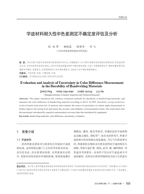
检测认证字迹材料耐久性中色差测定不确定度评估及分析■ 赵 萍 杨晓晨 陈雅华 刘 飞(上海市质量监督检验技术研究院)摘 要:本文介绍了目前字迹材料耐久性常用的评价方法,并根据DA/T 16-1995《档案字迹材料耐久性测试法》中色差的测试方法,对字迹材料色差进行测试,分析评估色差测量过程中不确定度的来源,以进一步提高检测水平,确保测量结果的准确性和可靠性。
结果显示,试样重复性引入的不确定度较大,设备引入的不确定度影响较小。
关键词:字迹材料,色差,不确定度,评估DOI编码:10.3969/j.issn.1002-5944.2023.24.032Evaluation and Analysis of Uncertainty in Color Difference Measurement in the Durability of Handwriting MaterialsZHAO Ping YANG Xiao-chen CHEN Ya-hua LIU Fei(Shanghai Institute of Quality Inspection and Technical Research)Abstract:This paper introduces the common evaluation methods for durability of handwriting materials, and measures the color difference of handwriting material according to DA/T 16-1995, Durability testing method for archival handwriting materials. It analyzes and evaluates the source of uncertainty in contact angle measurement to further improve the testing level and ensure the accuracy and reliability of measurement results. The result shows that the uncertainty introduced by repetitive measurement was more than that introduced by equipment.Keywords: handwriting materials, color difference, uncertainty, evaluation1 背景介绍1.1 字迹材料纸质档案是纸张及与纸张结合形成的字迹材料组成,这些材料记载了人文社科等发展及活动,是历史见证,具有重要的价值。
纳米外衣作文英语

纳米外衣作文英语Nano-clothing。
With the rapid development of science and technology, the application of nanotechnology in various fields has become more and more extensive. One of the most promising applications is the development of nano-clothing. Nano-clothing refers to clothing that has been treated with nanotechnology to improve its performance in terms of durability, comfort, and functionality. This technology has the potential to revolutionize the textile industry and change the way we think about clothing.One of the key benefits of nano-clothing is its durability. By treating the fabric with nanomaterials, it becomes more resistant to wear and tear, making it last longer than traditional clothing. This is especially important in today's fast fashion industry, where clothing is often discarded after only a few wears. Nano-clothing has the potential to reduce the environmental impact of thefashion industry by creating longer-lasting, more sustainable clothing.In addition to durability, nano-clothing also offers improved comfort. Nanotechnology allows for the creation of fabrics that are more breathable, moisture-wicking, and temperature-regulating. This means that nano-clothing can keep the wearer cool in hot weather and warm in cold weather, making it more versatile and comfortable to wear in a variety of conditions. This is especially importantfor outdoor enthusiasts and athletes who rely on their clothing to perform under demanding conditions.Furthermore, nano-clothing can also offer additional functionality. For example, nanotechnology can be used to create fabrics that are water-repellent, stain-resistant, and even antibacterial. This means that nano-clothing can stay clean and fresh for longer, reducing the need for frequent washing and extending the life of the garment. Additionally, nano-clothing can be designed with built-in UV protection, making it ideal for outdoor activities and protecting the wearer from the harmful effects of the sun.Overall, the development of nano-clothing has the potential to revolutionize the textile industry and change the way we think about clothing. By improving durability, comfort, and functionality, nano-clothing has the potential to create longer-lasting, more sustainable clothing that meets the needs of today's consumers. As nanotechnology continues to advance, we can expect to see even more innovative applications of nano-clothing in the future.。
- 1、下载文档前请自行甄别文档内容的完整性,平台不提供额外的编辑、内容补充、找答案等附加服务。
- 2、"仅部分预览"的文档,不可在线预览部分如存在完整性等问题,可反馈申请退款(可完整预览的文档不适用该条件!)。
- 3、如文档侵犯您的权益,请联系客服反馈,我们会尽快为您处理(人工客服工作时间:9:00-18:30)。
Modeling uncertainty in cutter wear prediction for tunnel boring machinesC. Frenzel 11Department of Mining Engineering, Colorado School of Mines, 1600 Illinois St,Golden, CO, 80401; PH (303) 273-3714; FAX (303) 273-3719; email:cfrenzel@ABSTRACTWear of cutting tools and the excavation performance of tunnel boringmachines (TBM) is influenced by a number of geotechnical parameters. Theprediction model of the Colorado School of Mines uses Uniaxial CompressiveStrength, Brazilian Tensile Strength, and Cerchar Abrasivity Index. Due to thecomplex nature of rock each of these parameters shows variance and there arecorrelations between these parameters.The usual approach to performance and wear prediction is to use averageinput parameters to estimate the “average” result. It is shown that this is not alwayscorrect because of the statistical nature of the input parameters.The approach described in this paper establishes a statistical model for theperformance and wear prediction based on the previously developed model. Since ananalytical solution for variance prediction is not possible for this model a Monte-Carlo simulation is used.PREDICTION OF DISC CUTTER WEARA broadly used model for prediction tunnel boring machine performance and disccutter wear has been developed at the Colorado School of Mines. Its first version waspublished by Ozdemir et al. 1977 and the last version was published by Rostami1997.To predict the wear of disc cutters two steps need to be followed:1. Prediction of the penetration rate2. Prediction of disc cutter lifeThe reason is that cutter life has been shown to be proportional to the rolling distanceof a disc cutter (Frenzel 2010).Penetration Rate. The prediction of the penetration rate is an iterative process sincethere are three basic limitations:• Thrust limit: Depending on the size of the disc cutter the bearing capacity of the disc cutters varies and limits the maximum thrust force that a disc cuttercan withstand.• Torque limit: The main drive of a tunnel boring machine can overcome only a certain maximum torque at a given rotational speed.• Geometrical limit: The geometry of disc cutter rings does not support infinite penetration rates because the shoulders of the cutter ring will eventually touchthe rock surface.D o w n l o a d e d f r o m a s c e l i b r a r y .o r g b y T o n g j i U n i v e r s i t y o n 04/13/14. C o p y r i g h t A S CE .F o r p e r s o n a l u s e o n l y ; a l l r i g h t s r e s e r ve d .Based on geometrical considerations the opening angle ϕ of the contact area betweenthe disc cutter and the rock can be calculated bywhere R is the radius of the disc cutter and p is the penetration rate.The average stress P* in the contact area can be estimated bywhere σc is the uniaxial compressive strength, σt is the Brazilian Tensile Strength(BTS), S is the spacing between adjacent disc cutter positions on the cutterhead, andT is the width of the tip of the cutter ring.The resulting cutting force F on the disc cutter is given byThis resulting force can be separated into a normal and a rolling component. Therolling component is critical because the sum of all rolling forces times their distancefrom the center of the cutterhead yields the required torque for the main drive of theTBM:where nc is the number of disc cutters on the cutterhead and Dc is the excavationdiameter of the cutterhead.These calculations are repeated until one of the three limits as shown abovehas been reached.Disc Cutter Life. The maximum rolling distance until a disc cutter has to be changeddue to primary wear iswhere CAI is the Cerchar Abrasivity index and R the radius of the disc cutter in mm.The average rolling distance of a disc cutter during one revolution of the cutterheadcan be approximated byD o w n l o a d e d f r o m a s c e l i b r a r y .o r g b y T o n g j i U n i v e r s i t y o n 04/13/14. C o p y r i g h t A S CE .F o r p e r s o n a l u s e o n l y ; a l l r i g h t s r e s e r ve d .where D c is the diameter of the cutterhead. Further analysis by Frenzel 2010revealed that actual cutter life was less than the expected value based on primarywear. Hence, a correctionis introduced where g i are the relative weights of the number of disc cutters in thecenter, face, and gage area. The corrections k k and k v can be determined fromTable 1.Table 1. Correction factors for cutter life at different cutterhead positionsCorrection k k Correction k vCentre cutters 0.561.0Face cutters 0.76 1.0Gage cutters 0.92 0.54The maximum number of cutterhead revolutions U cuntil a cutter changeoccurs can be calculated byand net cutter life V c is computed to bewhere S is the spacing of the disc cutters. Based on net cutter life the number of disccutter changes for a given tunnel can be predicted.INPUT PARAMETERSRock Strength. Due to inhomogeneity repeated tests for rock strengths yielddifferent results. If the number of tests is large enough (sufficient sample size) theresults can be used to estimate the (unknown) statistical distribution. That includesthe type of distribution and its parameters.Of course, measuring rock strengths already introduces a certain bias sinceany damage or imperfection of the sample will reduce its (apparent) strength. Bydefinition UCS should be the intact rock strength which means that there is a biastowards underestimating rock strengths using standard laboratory tests.Examples for histograms of UCS tests of rock samples from Hong Kong areshown in figures 1 and 2.D o w n l o a d e d f r o m a s c e l i b r a r y .o r g b y T o n g j i U n i v e r s i t y o n 04/13/14. C o p y r i g h t A S CE .F o r p e r s o n a l u s e o n l y ; a l l r i g h t s r e s e r ve d .Figure 1: Histogram of Uniaxial Compressive Strength of Hong Kong granite (after: Frenzel 2010).Figure 2: Histogram of Uniaxial Compressive Strength of Hong Kong tuff (after: Frenzel 2010).Neither of these two examples represents a normal distribution, but both showa distinct asymmetry. That could be explained by geology: The Hong Kong granitehad its highest strength after being created and weathering started to degrade the freshrock which led to lower rock strength. That results in a skew towards the left (i.e.lower rock strengths).On the other hand the Hong Kong tuff is metamorphic which eventuallyincreased its strength, but not in a perfectly homogenous manner. That explains theskew towards the right (i.e. higher rock strengths).D o w n l o a d e d f r o m a s c e l i b r a r y .o r g b y T o n g j i U n i v e r s i t y o n 04/13/14. C o p y r i g h t A S CE .F o r p e r s o n a l u s e o n l y ; a l l r i g h t s r e s e r ve d .The difficulty to estimate statistical distributions is to obtain a sufficientsample size. This could be substituted by a small number of tests if the type ofdistribution was linked to the geology of the rock. That should be subject of furtherresearch.Cerchar Abrasivity Index. Abrasivity of rock can be characterized by index tests orby its mineralogy. The most common index test is the Cerchar Abrasivity Index(CAI). However, since its results are influenced by a number of rock properties like:• Mineralogy • Strength of grain bounds• Grain size • Shape of grainsthere is an inherent variability to this parameter as well. In addition, several issues have been identified and discussed in regards to the test itself (Plinninger 2002,Rostami 2005, Käsling et al. 2007).Correlations. UCS and BTS are correlated for many specific rock types and this hasbeen shown as a ratio (Gunsallus & Kulhawy 1987, Heyne 1980). Since the ratiobetween UCS and BTS easily ranges from as low as 5 up to 20 there is the questionhow strong this correlation is.A correlation analysis for UCS, BTS, and CAI has been conducted to evaluatevariances and correlations between these parameters. The data were taken from 20different tunneling projects including a range of different rock types. The results aredepicted in table 2.Table 2: Empirical standard deviations and correlation coefficient for UCS,BTS, and CAI from 20 tunneling projects.UCS BTS CAIUCS s =63.3 MPa R =0.79 R =0.75BTS s = 5.6 MPa R =0.75CAI s = 1.5Although the dataset included many different rock types ranging fromsedimentary through metamorphic to igneous and volcanic there are clear positivecorrelations. This means that there is a bigger probability that a sample with a highUCS value also exhibits a high BTS and a high CAI value. The opposite also holdstrue. This has implications on the prediction of cutter life since using average valueswould underestimate the probability of extreme combinations of UCS, BTS, and CAI.STOCHASTIC EXTENSION OF THE PREDICTION MODELThe stochastic model of cutter life prediction can be expressed as the followingfunctionD o w n l o a d e d f r o m a s c e l i b r a r y .o r g b y T o n g j i U n i v e r s i t y o n 04/13/14. C o p y r i g h t A S CE .F o r p e r s o n a l u s e o n l y ; a l l r i g h t s r e s e r ve d .where the penetration p and abrasivity CAI are the random variables. Randomvariables are printed in grey to distinguish them from non-random input parameters.In addition, the penetration p can be expressed as a function of the random variablesUCS and BTS:The stochastic model reflects the variances σ and correlations ρ of the random variables and assumes normal distributions as an approximation:For linear problems an analytical approach can be taken to predict thevariance of the results. However, in this specific case the prediction model is iterativeand non-linear which requires a different approach.Monte-Carlo-Simulation. A numerical solution to calculate the characteristics ofsuch a problem is the Monte-Carlo-Method. It is based on generating a large numberof input data sets and to calculate the result for each input data set. The results canthen be characterized using descriptive statistics.Generating input data sets requires some specific steps to ensure that the datasets exhibit the correct distribution functions and show the correct correlations.Typically, programming language only provide functions for pseudo-random numbergeneration that follow an equal distribution. Three of these random numbers areconverted into normal-distributed random numbers using the central limit theorem.Finally, correlations are introduced by using a Cholesky repartition of the variance-covariance matrix and transformation by the mean.Example. To analyze the consequences of the considerations above an example hasbeen studied. The input parameters are summarized in table 3.Table 3: Input parameters for cutter life predictionMean UCS 150 MPaExcavation diameter 9.0 mMean BTS 10 MPa Disc cutter diameter 432 mmMean CAI 3.8 Max cutter load 267 kNVariance of UCS 50 MPa Spacing 90 mmVariance of BTS 3 MPa Disc cutter tip width 19 mmVariance of CAI 0.5 Number of disc cutters 57Covariance UCS-BTS 0.78 Cutterhead speed 5.3 1/minCovariance UCS-CAI 0.7 Cutterhead torque 5.77 MNmCovariance BTS-CAI 0.7D o w n l o a d e d f r o m a s c e l i b r a r y .o r g b y T o n g j i U n i v e r s i t y o n 04/13/14. C o p y r i g h t A S CE .F o r p e r s o n a l u s e o n l y ; a l l r i g h t s r e s e r ve d .The simulation was run using 10,000 iterations. The resulting distribution ofpenetration and cutter life is shown in figures 3 and 4.Figure 3: Histogram of penetration rate of Monte-Carlo-SimulationFigure 4: Histogram of cutter life of Monte-Carlo-SimulationBoth histograms show a right-skewed distribution which is a result of the non-linearity of the prediction model. The peak at a penetration rate of 10 mm in figure 3D o w n l o a d e d f r o m a s c e l i b r a r y .o r g b y T o n g j i U n i v e r s i t y o n 04/13/14. C o p y r i g h t A S CE .F o r p e r s o n a l u s e o n l y ; a l l r i g h t s r e s e r ve d .can be explained by the transition between thrust and torque limitation as discussedearlier. For comparison purposes table 4 shows the comparison between a predictionusing average values versus the results obtained through Monte-Carlo simulation.Table 4: Comparison of Monte-Carlo simulation and static prediction usingmean input valuesPenetration Rate [mm] Cutter Life [m 3]Monte-Carlo simulation 9.1 486 Mean values without simulation 8.3 398DISCUSSIONThe differences between the Monte-Carlo simulation and the static prediction show adifference of 10% for the average penetration rate and a difference of 22% for cutterlife. The difference for penetration rate prediction is probably neglectable forpractical purposes. However, the difference of 22% for cutter life is significant andcannot be disregarded easily. However, it is important to run the simulation on bothvalues because the penetration rate influencing the cutter life.CONCLUSIONBased on the prediction model for penetration rate and cutter life prediction for tunnelboring machines developed at the Colorado School of Mines a methodologyaccounting for the inherent uncertainties of rock is introduced. The model usesUniaxial Compressive Strength, Brazilian Tensile Strength, and the CercharAbrasivity Index as geotechnical input parameters.Through extensive testing the statistical distribution of these parameters canbe determined. Typically, the type of distribution is a normal distribution, butdepending on geology this may be skewed significantly as shown on the example ofgranite and tuff from Hong Kong.In addition, there are high correlations between these three parameters whichmean that there is a higher probability of a high UCS value occurring along with ahigh BTS value and a high CAI value. This leads to an increased variance of theresulting penetration rate and cutter life compared to the variance of the inputparameters.The existing prediction model can be used as the basis for a Monte-Carlosimulation which incorporates the random nature of the input parameters and whichallows to study the characteristics of the results.Through a calculated example it becomes clear that although the differencesbetween a simulation and a static calculation using average input values may lead tosignificant differences for predicted cutter life.D o w n l o a d e d f r o m a s c e l i b r a r y .o r g b y T o n g j i U n i v e r s i t y o n 04/13/14. C o p y r i g h t A S CE .F o r p e r s o n a l u s e o n l y ; a l l r i g h t s r e s e r ve d .REFERENCESFrenzel, Christian (2010): Verschleisskostenprognose für Schneidrollen beimaschinellen Tunnelvortrieben in Festgesteinen , Münchner GeowissenschaftlicheAbhandlungen, Reihe B, Dr. Friedrich Pfeil, MünchenGunsallus, K.L.; Kulhawy, F. H. (1987): “A comparative evaluation of rock strengthmeasures.” International Journal of Rock Mechanics and Mining Sciences , 24 (3),193–196.Heyne, K.-H. (1980): “Mathematisch-statistische Zusammenhänge zwischengesteinsmechanischen und gesteinsphysikalischen Kennwerten.“ Zeitschrift fürangewandte Geologie, 26 (10), 519–523Käsling, Heiko; Thiele, Inke; Thuro, Kurosch (2007): "Abrasivitätsuntersuchungenmit dem Cerchar-Test - eine Evaluierung der Versuchsbedingungen.“ 16. Tagung fürIngenieurgeologie und Forum "Junge Ingenieurgeologen", Bochum, 229–235Ozdemir, Levent; Miller, Russell; Wang, Fun-Den (1977): Mechanical tunnel boringprediction and machine design . Annual report , Colorado School of Mines, NationalScience Foundation, Washington, DCPlinninger, Ralf J. (2002): Klassifizierung und Prognose von Werkzeugverschleiß beikonventionellen Gebirgslösungsverfahren im Festgestein. Münchner geologischeHefte, Reihe B, MünchenRostami, Jamal (1997): Development of a force estimation model for rockfragmentation with disc cutters through theoretical modeling and physicalmeasurement of crushed zone pressure, PhD thesis, Colorado School of Mines,Golden.Rostami, Jamal (2005): “CAI testing and its implications.” Tunnels & TunnellingInternational , October, 43–45D o w n l o a d e d f r o m a s c e l i b r a r y .o r g b y T o n g j i U n i v e r s i t y o n 04/13/14. C o p y r i g h t A S CE .F o r p e r s o n a l u s e o n l y ; a l l r i g h t s r e s e r v e d .。