ANSI EIA RS-186-8E
浅谈照明镇流器IEC及ANSI两大标准体系

浅谈照明镇流器IEC及ANSI两大标准体系本文以一个专业生产荧光灯用电子镇流器的美国独资公司标准化工作者的角度论述当今全球照明电子镇流器两大标准体系IEC与ANSI/UL及其衍生的EN标准,中国的国标和CCC认证以及推广中的CB认证的内容,从而引申出企业在中国加入WTO后的标准化工作新思路。
关键词:贸易技术壁垒,标准化战略。
一、引言作为一家专业生产电子镇流器的美国独资企业,环球迈特以其质量,性能,价格的整合优势赢得了业内的口碑,也引得美洲,欧洲,亚洲各国多方客户的纷至沓来。
随着市场在这些区域的渗透和拓展,又逢中国加入WTO的契机,产品标准化和认证工作便被赋予了新的内涵。
刚从北京参加完IEC 66届年会的原环球总部副总裁,原美国全国电气制造商协会NEMA的理事长,资深标准化顾问Michael Stein先生专程来上海给我们做了一次IEC, ANSI等相关标准的专题演讲;原摩托罗拉电光源公司,现任OSRAM Sylvania标准化战略策划的Howad Wolfma n先生也给我们Email来了他在中国绿色照明国际研讨会上的论文。
受此启发,我们查阅了相关网站,文献资料,标准化杂志,整理出如下国内外一系列有关照明系统的标准论述对照和由此引出的标准化工作的思考。
二、国际电工委员会IEC相关标准标准是一种世界各地各种业务用以开发产品,服务和相关体系的技术语言,也是国际市场买卖双方为交换产品和服务建立信用度的基础。
产品要进入国际大市场的必要条件,包括国际认可的标准,以及验证这些标准要求的认证活动。
但我国的标准化水平不容乐观。
有数据表明,截止2000年底,GB颁布19278款,采用IEC国际标准的采标率仅43.5%;同时由我国起草的国际标准只有13项。
另有一例,受贸易技术壁垒影响,占我国出口额第一位的机电类产品,由于受发达国家在噪声,电磁污染,节能性,兼容性,安全性等方面的技术标准限制,仅1992年就有8 0多亿美元的出口产品交易受到影响而未果。
电感式传感器 BI2-EM12-Y1X-H1141说明书

T 07:17:00+02:00型号BI2-EM12-Y1X-H1141货号4010201额定工作距离Sn 2 mm 安装方式齐平实际测量范围ð (0,81 x Sn) mm修正系数37#钢 = 1; 铝 = 0.3; 不锈钢= 0.7; 黄铜 = 0.4重复精度ð 2 满量程的 %温度漂移10 %磁滞1…10 %环境温度-25…+70 °C 输出性能2线, NAMUR 开关频率 5 kHz电压Nom. 8.2 VDC 无激励电流损耗ï 2.1 mA 激励电流损耗ð 1.2 mA认证依据KEMA 02 ATEX 1090X 内置 电感(L ) / 电容 (C )150 nF / 150 µH防爆标志防爆标识为II 1 G/Ex ia IIC T6/II 1 D Ex ia D 20 T115°C Da(最大 U = 20 V, I = 20 mA, P = 200 mW)设计圆柱螺纹, M12 x 1尺寸52 mm外壳材料不锈钢型, V2A (1.4301)感应面材料塑料, PA 最大扭矩10 Nm连接接插件, M12 x 1防震动性55 Hz (1 mm)防冲击性30 g (11 ms)防护等级IP67MTTF 6198 years 符合SN 29500 (Ed.99) 40 °C认证开关状态指示LED指示灯 黄sATEX 防爆认证II 组设备,设备等级1G. 可用于气体危险0区sATEX 防爆认证II组设备,设备等级1D,可应用于粉尘危险2区s 满足SIL2和IEC61508标准s M12 x 1圆柱螺纹s 不锈钢1.4301s 2线直流, nom. 8.2 VDCs输出遵循本安型DIN EN 60947-5-6(NAMUR)标准sM12 x 1接插件接线图功能原理电感式传感器以非接触和无磨损的方式检测金属物体。
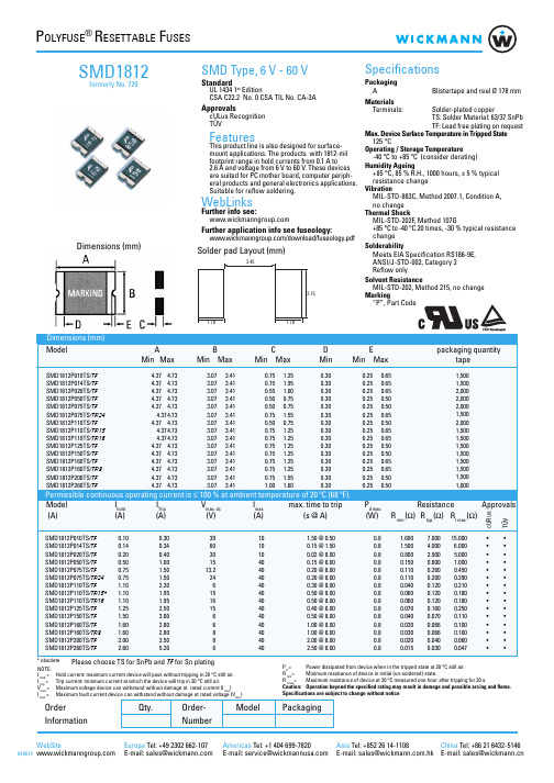
自恢复保险丝SMD1812
100.000 10.000 1.000
BC A
DEF
SMD1812
A:SMD1812P010TS/TF B:SMD1812P014TS/TF C:SMD1812P020TS/TF D:SMD1812P050TS/TF E:SMD1812P075TS/TF F:SMD1812P075TS/TF/24
0.75 1.25
0.30
0.75 1.95
0.30
0.55 1.00
0.30
0.50 0.75
0.30
0.50 0.75
0.30
0.75 1.55
0.30
0.50 0.75
0.30
0.75 1.25
0.30
0.75 1.25
0.30
SMD1812P125TS/TF
4.37 4.73
3.07 3.41
3.45
3.15
Specifications
Packaging A
Blistertape and reel Ø 178 mm
Materials
Terminals:
Solder-plated copper
TS: Solder Material: 63/37 SnPb
TF: Lead free plating on request
resistance change
Vibration
MIL-STD-883C, Method 2007.1, Condition A,
no change
Thermal Shock
MIL-STD-202F, Method 107G
+85 °C to -40 °C 20 times, -30 % typical resistance
258 Encoders 金属杆壳型绝对类型 EC18A 水抗性强、重力扭矩强 18mm 尺寸 金属

259EncodersMetal ShaftInsulatedShaftThroughShaft TypeRing TypeStandard Codes 1. The ●marks shows the ON position.2. The ●marks : Connections between terminals and the 5 (COM) are ON.Waterproof PropertyImmersion of encoder, not in operation, in water at depth of 1m at normal temperature for 30 minutes.EC18AGAPosition No.123456789101112Rotation angle (° )3060901201501802102402703003301●●●●●●2●●●●3●●●●●●4●●●●5(COM )●●●●●●●●●●●●T E R M I N A L N O .EC18AGB20401Position No.12345678910111213141516Rotation angle (° )22.54567.590112.5135157.5180202.5225247.5270292.5315337.51●●●●●●●●2●●●●●●●●3●●●●●●●●4●●●●●●●●5(COM )●●●●●●●●●●●●●●●●T E R M I N A L N O .EC18AGB20407Position No.123456789101112131415Rotation angle (° )244872961201441681922162402642883123361●●●●●●●●2●●●●●●●●3●●●●●●●●4●●●●●●●●5(COM )●●●●●●●●●●●●●●●T E R M I N A L N O .EC18A /18mm Size Insulated Shaft Type(Two phase A and B )275EncodersMetal ShaftInsulated Shaft Through Shaft TypeRing Type1. When using an infrared reflow oven, solder may sometimes not be applied. Be sure to use a hot air reflow oven or a type that uses infrared rays in combination with hot air.2. The temperatures given above are the maximum temperatures at the terminals of the encoder when employing a hot air reflow method. The temperature of the PC board and the surface temperature of the encoder may vary greatly depending on the PC board material, its size and thickness. Ensure that the surface temperature of the encoder does not rise to 250℃ or greater.3. Conditions vary to some extent depending on the type of reflow bath used. Be sure to give due consideration to this prior to use.NotesEC05E EC21CEC28C, EC35CH250℃ min.230℃ to 245℃260℃230℃ min.220℃ 230℃180℃200℃180℃150℃150℃150℃60s to 120s 60s to 120s 2 min. min.ーー3s30s to 40s 25s to 60s40sー300s max.230s max.2 times max.1 time max.1 time max.Soldering surfacetemperatureSoldering temperatureHeating timeSoldering timeNo. of soldersEC09E, EC111, EC11E, EC11M, EC11N, EC18A,EC21A, EC28A, EC35A, EC35AH, EC50A Series100℃ max.260±5℃2 min. max.5±1s 2 times max.PreheatingDip solderingReference for Dip SolderingExample of Reflow Soldering ConditionReference for Manual SolderingEC10E, EC12D, EC12E EM11BEC40A100℃ max.100℃ max.110℃ max.260±5℃260℃ max.260℃ max.1 min. max.1 min. max.1 min. max.3±1s 3s max.10s max.2 times max.2 times max.1 timeTemperature profile300200100A BC Time (s)G max.F max.H max.E max.RoomtemperatureT e m p e r a t u r e (˚C )Pre-heating DEncoders / Soldering ConditionsEC05E, EC09E, EC10E, EC111, EC11E, EC11M, EC11N, EC12D, EC12E, EC18A, EC21A, EC28A, EC35A, EC35AH, EC40A, EC50A, EM11B, EC21C, EC28C, EC35CHSeries350℃ max.3s max. 1 timeTip temperatureSoldering timeNo. of soldersSeries ABCDEFGHNo. of reflows。
ifm电子流量计器产品说明书
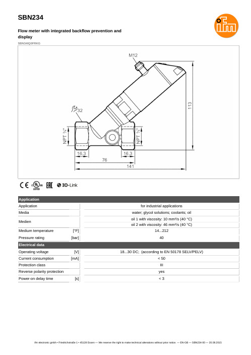
Resolution
Set point SP
Reset point rP
Measuring dynamics
Frequency end point, FEP
Frequency at the end point FRP
[Hz]
In steps of
0.2...10 gpm 0...12 gpm
0.1 gpm 0.1...10 gpm 0...9.9 gpm
stainless steel (1.4401 / 316); stainless steel (1.4404 / 316L); brass (2.0371); brass chemically nickel-plated; PPS; O-ring: FKM
Process connection
threaded connection 3/4 NPT
hysteresis / window; normally open / normally closed; switching logic; current output; medium selection; damping for the switching output / analogue output; display can be rotated and switched off; standard unit of measurement; process value colour
SBN234
Flow meter with integrated backflow prevention and display
SBN34IQ0FRKG
Connection
OUT1: OUT2: -
BK = BN = BU = WH =
有关profibus芯片

产品型号:ADM2486 (宽体封装BRWZ)产品类别:隔离型RS485生产厂商:ADI主要用途:RS485通讯,专为PROFIBUS定制产品描述:数据速率达到20M、半双工、隔离2500V、隔离型RS485收发器ADM24861 差分总线收发器是一款集成式电流隔离器件,适用于多点总线传输线路的双向数据通信。
它针对平衡传输线路而设计,符合ANSI TIA/EIA RS-485-A和ISO 8482:1987(E)标准。
该器件采用ADI公司的iCoupler技术,将3通道隔离器、三态差分线路驱动器和差分输入接收器集成于单封装中。
器件逻辑端可以采用5 V或3 V电源供电,总线端则采用5 V电源供电。
ADM2486驱动器具有高电平有效使能特性。
驱动器差分输出与接收器差分输入内部相连,形成差分输入/输出端口;当驱动器禁用时,或者当VDD1 或VDD2=0V时,该端口向总线提供极小的负载。
该器件还具有高电平有效接收器禁用特性,可使接收器输出进入高阻抗状态。
该器件具有限流和热关断特性,可防止发生输出短路以及总线竞争导致功耗过大的情况SPC3(SIMENS PROFIBUS CONTROLER)是一种用于PROFIUBS-DP开放式工业现场总线智能化接口芯片,可广泛用于工业自支化和楼宇管理自动化中的单片机接口。
SPC3集成了完整的DP协议,其中包括方式寄存器、状态寄存器、中断寄存器、各种缓冲器指针和缓冲区等。
有效地减轻了处理器的压力,因此可用于12Mbaud总线。
该芯片内部含有1.5KB的双口RAM作为SPC3与软件/程序的接口。
带有11位地址线的并行8位接口,全部存储器分为192段,每段8个字节,用户可以立即寻址。
SPC3支持所有8位处理机和微处理器。
也可以自动完成“字节转换”,这使得摩托罗拉处理器可以直接正确读取16位值,通常读和写可通过两个口(8位数据总线)来完成。
用户寻址由内部MS通过基址指针来实现,基址指针可位于存储器的任何段。
超低电阻0603封装保险丝
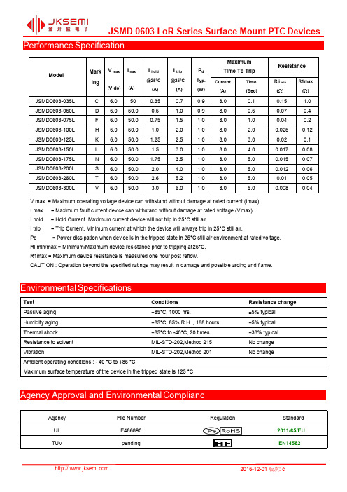
Performance SpecificationModelMarking V max(V dc)I max(A)I hold@25°C(A)I trip@25°C(A)P dTyp.(W)MaximumTime To TripResistanceCurrent(A)Time(Sec)R i min(Ω)R1max(Ω)JSMD0603-035L C 6.0500.350.70.98.00.10.15 1.0 JSMD0603-050L D 6.050.00.5 1.00.98.00.60.070.4 JSMD0603-075L F 6.050.00.75 1.5 1.08.0 1.00.040.2 JSMD0603-100L H 6.050.0 1.0 2.0 1.08.0 2.00.0250.12 JSMD0603-125L K 6.050.0 1.25 2.5 1.08.0 3.00.020.1 JSMD0603-150L L 6.050.0 1.5 3.0 1.08.0 4.00.0170.08 JSMD0603-175L N 6.050.0 1.75 3.5 1.08.0 5.00.0150.07 JSMD0603-200L S 6.050.0 2.0 4.0 1.08.0 5.00.0120.06 JSMD0603-260L T 6.050.0 2.6 5.2 1.08.0 5.00.010.05 JSMD0603-300L V 6.050.0 3.0 6.0 1.08.0 5.00.0080.04V max=Maximum operating voltage device can withstand without damage at rated current(Imax).I max=Maximum fault current device can withstand without damage at rated voltage(Vmax).I hold=Hold Current.Maximum current device will not trip in25°C still air.I trip=Trip Current.Minimum current at which the device will always trip in25°C still air.Pd=Power dissipation when device is in the tripped state in25°C still air environment at rated voltage.Ri min/max=Minimum/Maximum device resistance prior to tripping at25°C.R1max=Maximum device resistance is measured one hour post reflow.CAUTION:Operation beyond the specified ratings may result in damage and possible arcing and flame.Environmental SpecificationsTest Conditions Resistance change Passive aging+85°C,1000hrs.±5%typicalHumidity aging+85°C,85%R.H.,168hours±5%typicalThermal shock+85°C to-40°C,20times±33%typical Resistance to solvent MIL-STD-202,Method215No changeVibration MIL-STD-202,Method201No changeAmbient operating conditions:-40°C to+85°CMaximum surface temperature of the device in the tripped state is125°CAgency Approval and Environmental CompliancAgency File Number Regulation StandardUL E4868902011/65/EUTUV pending EN14582TP20~40S TP260TL217t L60~150s200150tsPreheat60~180s25t25°C to peakTimeRamp-downCritical ZoneTL to TP TsminTsmaxRamp-upThermal Derading ChartRecommended Hold Current(A)at Ambient Temperature(°C)Soldering ParametersModelAmbient OperationTemperature-40°C-20°C0°C25°C40°C50°C60°C70°C85°C JSMD0603-035L0.460.40.370.350.290.250.240.20.14 JSMD0603-050L0.660.570.530.50.410.360.340.290.2 JSMD0603-075L0.990.860.790.750.620.540.510.430.3 JSMD0603-100L 1.31 1.14 1.06 1.00.830.710.690.570.4 JSMD0603-125L 1.64 1.43 1.32 1.25 1.040.890.860.710.5 JSMD0603-150L 1.97 1.71 1.59 1.5 1.24 1.07 1.030.860.6 JSMD0603-175L 2.3 2.0 1.85 1.75 1.45 1.25 1.2 1.00.7 JSMD0603-200L 2.63 2.29 2.11 2.0 1.66 1.43 1.37 1.140.8 JSMD0603-260L 3.42 2.97 2.75 2.6 2.15 1.86 1.78 1.49 1.04 JSMD0603-300L 3.94 3.43 3.17 3.0 2.49 2.14 2.06 1.71 1.2Profile FeaturePb-Free Assembly Average Ramp-Up Rate(Ts max to T p)3℃/second mac.Preheat-Temperature Min(Ts min)-Temperature Max(Ts max)-Time(Ts min to Ts max)150℃200℃60~180seconds Time maintained above:-Temperature(TL)-Time(tL)217℃60~150seconds Peak Temperature(Tp)260℃Ramp-Down Rate6℃/second max.Time 25℃to Peak Temperature 8minutes max Storage Condition0℃~35℃,≤70%RH Recommended reflow methods:IR,vapor phase oven,hot air oven,N2environment for lead-freeRecommended maximum paste thickness is 0.25mmDevices can be cleaned using standard industry methods and solvents.Note 1:All temperature refer to topside of the package,measured on the package body surface.Note 2:If reflow temperatures exceed the recommended profile,devices may not meet the performance requirements.Physical Dimensions(mm.)Termination Pad CharacteristicsTerminal pad materials :Tin-plated Nickel-CopperTerminal pad solder ability :Meets EIA specification RS186-9E and ANSI/J-STD-002Category 3Model ABCD E Min.Max.Min.Max.Min.Max.Min.Min.JSMD0603-035L 1.45 1.850.65 1.050.30.70.150.1JSMD0603-050L 1.45 1.850.65 1.050.30.70.150.1JSMD0603-075L 1.45 1.850.65 1.050.30.70.150.1JSMD0603-100L 1.45 1.850.65 1.050.4 1.00.150.1JSMD0603-125L 1.45 1.850.65 1.050.4 1.00.150.1JSMD0603-150L 1.45 1.850.65 1.050.5 1.20.150.1JSMD0603-175L 1.45 1.850.65 1.050.5 1.20.150.1JSMD0603-200L 1.45 1.850.65 1.050.7 1.40.150.1JSMD0603-260L 1.45 1.850.65 1.050.7 1.40.150.1JSMD0603-300L1.451.850.651.050.71.40.150.1Recommended Pad Layout (mm.)Packaging QuantityTape &reel packaging per EIA481-1Tape And Reel Specifications (mm)Storage And Handling‧Storage conditions :35°C max,70%R.H.‧Devices may not meet specified performance if storage conditions are exceeded.Part Number Quantity JSMD 0603LoR Series5,000pcs/reelGoverning Specifications EIA 481-1W 8.0±0.2P0 4.0±0.10P1 4.0±0.10P2 2.0±0.05A0 1.05±0.10B0 1.85±0.10D0 1.55+0.10F 3.5±0.05E1 1.75±0.10E2min. 6.25T 0.75T1max.0.1K00.74/0.95±0.1Leader min.390Trailer min.160Reel Dimensions A max.178N min.60W19.0±0.5W212.0±0.05JSMD0603Series Surface Mount PTC Devices Part Number SystemWebsite:For additional information,please contact your local SalesRepresentative.©Copyright2016,jksemiis a registered trademark of jksemi All rights arereserved。
CommScope Cat5e F UTP彻通电缆(白色外壳,1000英尺,4对)说明书
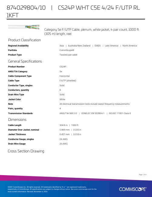
Category 5e F/UTP Cable, plenum, white jacket, 4 pair count, 1000 ft(305 m) length, reelProduct ClassificationRegional Availability Asia | Australia/New Zealand | EMEA | Latin America | North America Portfolio CommScope®Product Type Twisted pair cableGeneral SpecificationsProduct Number CS24PANSI/TIA Category5eCable Component Type HorizontalCable Type F/UTP (shielded)Conductor Type, singles SolidConductors, quantity8Drain Wire Type SolidJacket Color WhiteNote All electrical transmission tests include swept frequency measurementsPairs, quantity4Transmission Standards ANSI/TIA-568.2-D | CENELEC EN 50288-6-1 | ISO/IEC 11801 Class E DimensionsCable Length304.8 m | 1000 ftDiameter Over Jacket, nominal 5.969 mm | 0.235 inJacket Thickness0.457 mm | 0.018 inConductor Gauge, singles24 AWGDrain Wire Gauge26 AWGCross Section Drawing14Page ofElectrical SpecificationsCharacteristic Impedance100 ohmdc Resistance Unbalance, maximum 5 %dc Resistance, maximum9.38 ohms/100 m | 2.859 ohms/100 ftDelay Skew, maximum15 nsDielectric Strength, minimum1500 Vac | 2500 VdcMutual Capacitance at Frequency 5.6 nF/100 m @ 1 kHzNominal Velocity of Propagation (NVP)73 %Operating Frequency, maximum100 MHzOperating Voltage, maximum80 VRemote Powering Fully complies with the recommendations set forth by IEEE 802.3bt (Type 4) for thesafe delivery of power over LAN cable when installed according to ISO/IEC 14763-2,CENELEC EN 50174-1, CENELEC EN 50174-2 or TIA TSB-184-ASafety Voltage Rating300 V24Page ofElectrical Cable PerformanceCS CommScopeSTD Refers to the standard value listed under Transmission Standards in the Electrical Specifications aboveTYP Typical Electrical PerformanceIL Insertion Loss (dB/100m)NEXT Near End Crosstalk (dB/100m)ACR Attenuation to Crosstalk Ratio (dB/100m)PSNEXT Power Sum Near End Crosstalk (db/100m)PSACR Power Sum Attenuation to Crosstalk Ratio (dB/100m)ACRF Attenuation to Crosstalk Ratio - Far End (dB/100m) PSACRF Power Sum Attenuation to Crosstalk Ratio - Far End (dB/100m)RL Return Loss (dB)TCL Transverse Conversion Loss (dB/100m)ELTCTL Equal Level Transverse Conversion Transfer Loss (dB/100m)Freq. MHzIL NEXT ACR PSNEXT PSACR ACRF PSACRF RL STD TYP STD TYP STD TYP STD TYP STD TYP STD TYP STD TYP STD TYP12 1.965.383.163.381.262.380.860.378.963.884.460.882.420334 4.1 3.756.373.452.269.853.371.349.267.651.873.348.871.42330.68 5.8 5.251.8694663.948.8674361.845.767.442.765.524.531.510 6.5 5.850.367.243.861.447.365.140.859.343.865.440.863.52532.4168.27.447.264.13956.844.2623654.739.761.336.759.42531.8209.38.245.862.636.554.442.860.533.552.237.859.434.857.425332510.49.244.360.933.951.641.358.830.949.635.857.632.855.524.333.131.2511.710.342.959.631.249.239.957.428.247.133.955.630.953.523.633.462.51714.738.454.421.439.835.452.418.437.727.949.524.947.421.532.91002218.635.35113.332.432.348.910.330.223.845.520.843.320.129.915523.446.923.545.121.741.339.32820026.745.118.443.216.539.1372625029.944.814.942.712.837.135.125.130032.94310.140.9835.633.42535035.741.6 5.939.7 3.934.131.825.6Material SpecificationsConductor Material Bare copperDrain Wire Material Tinned copperInsulation Material FEPJacket Material PVCShield (Tape) Material Aluminum/PolyesterMechanical SpecificationsPulling Tension, maximum11.34 kg | 25 lbEnvironmental SpecificationsInstallation temperature0 °C to +60 °C (+32 °F to +140 °F)Operating Temperature-20 °C to +60 °C (-4 °F to +140 °F)Page of34Environmental Space PlenumFlame Test Method CMP/FT6 | NEC Article 800 | NFPA 262 | UL 444 | UL 910 Smoke Test Method CMP/FT6Packaging and WeightsCable weight44.05 kg/km | 29.6 lb/kftPackaging Type ReelRegulatory Compliance/CertificationsAgency ClassificationCHINA-ROHS Below maximum concentration valueISO 9001:2015Designed, manufactured and/or distributed under this quality management system REACH-SVHC Compliant as per SVHC revision on /ProductComplianceROHSCompliantPage of44。
2920封装系列贴片保险丝
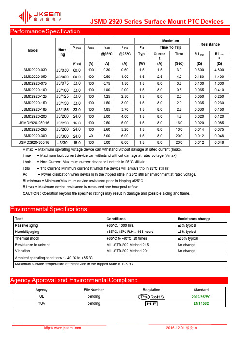
I trip = Trip Current. Minimum current at which the device will always trip in 25°C still air.
Pd
= Power dissipation when device is in the tripped state in 25°C still air environment at rated voltage.
Thermal Derating Curve
Derating Curves for JSMD2920 Series
160 140 120 100
80 60 40 20
0
-40
-20
0
20
40
Temperature (°C)
Average Time-Current Curve
100
Average Time Current Curves
Curren t
(A)
Time (Sec)
Resistance
R i min ()
R1ma
x
()
JSMD2920-030 JS/030 60.0 100 0.30
0.60
1.5
1.5
3.0
0.600
4.800
JSMD2920-050 JS/050 60.0 100 0.50
1.00
1.5
2.5
4.0
0.88
0.75
0.62
0.56
JSMD2920-100
1.66
1.47
1.29
1.10
0.91
0.83
JSMD2920-125
1.89
PPTC自恢复保险丝MSM Series

FeaturesApplicationsSurface Mount Devices Almost anywhere there is a low voltage Lead free deivce power supply,up to DC33V and a load Size 4532mm/1812milsto be protested,including:Surface Mount packaging for automated assembly Computer mother board,Modem,USB hub Agency recognition:ULPDAs &Charger,Analog &digital line card Digital cameras,Dish drivers,CD-ROMsModelD E minmax min max minmaxmin min 4.374.733.073.410.50 1.000.300.251.000.300.25ABC4.37 4.73 3.07 3.410.50 1.004.37 4.73 3.07 3.410.501.300.300.254.374.73 3.07 3.410.50 1.000.300.25MSM050/24/30 4.37 4.73 3.07 3.410.40 1.800.300.25 4.374.73 3.07 3.410.40 0.900.300.254.37 4.73 3.07 3.410.40 1.300.300.25 MSM1254.37 4.73 3.07 3.410.60 1.300.300.254.37 4.73 3.07 3.410.40 1.200.300.25 MSM160 4.37 4.73 3.07 3.410.40 1.200.300.254.37 4.73 3.07 3.410.50 1.300.300.25 4.374.73 3.07 3.410.50 1.500.300.25Test Passive aging Humidity aging Thermal shock Resistance to solventVibrationMaximum surface of the device in the tripped state is 125℃85℃,85%℃R.H.,168hrs 85℃,to-40℃,13times ±5%typical ±5%typical ±33%typical Ambient operating confitions:-40℃to 85℃Conditions MIL-STD-202,Method 215MIL-STD-202,Method 201Resistance changeNo change No change85℃,1000hrsMSM 300 4.37 4.73 3.07 3.410.50 1.500.300.25 MSM 3504.374.733.073.410.50 1.500.300.25PPTC /M SM Ser ies01 | spsemiMSM020/60MSM075/16/24/33MSM110/16/24/33MSM150/16/24MSM200/12MSM260/13.2/16MSM010MSM014MSM030REV.2014.05.01Model Ihold Itrip Vmax Imax Pd max Current TimeRmin Rmax (A)(A)(Vdc)(A)(w)(A)(S)(Ω)(Ω)MSM0100.100.30301000.80.5 1.50.75015.000MSM0140.140.34 601000.8 1.50.150.650 6.000MSM0200.200.40301000.88.00.020.350 5.000MSM0300.300.60301000.88.00.10.250 3.000MSM0500.501.00151000.88.00.150.1501.000MSM050/240.50 1.00 241000.88.00.150.150 1.000MSM075 0.75 1.50 13.2 1000.88.00.20.0900.450 MSM 110 1.10 2.20 81000.88.00.30.0500.2501.10 2.20 161000.88.00.30.0500.2501.50 3.00 8 1000.88.00.50.0400.1601.50 3.00 241000.88.00.50.0400.1601.60 2.80 8 1000.88.0 1.00.0300.1302.00 4.0081000.88.0 2.00.0200.1002.60 5.00 8 1000.88.0 2.50.0150.0503.00 5.0081000.88.0 4.0 0.0120.0403.50 6.00 6 1000.88.0 4.0 0.0080.030Ihold Itrip Vmax Imax PdRmin/max R1max*CAUTIONModel—40℃—20℃0℃25℃40℃50℃60℃70℃85℃MSM0100.1600.140.1200.100.0800.070.060.050.030MSM0140.230.190.170.140.1200.100.090.080.06MSM0200.290.260.230.200.1700.150.140.120.10MSM0300.440.390.350.300.2600.230.210.180.15MSM0500.590.570.550.500.4500.430.350.300.23MSM075 1.100.990.870.750.6300.570.490.450.35MSM110 1.60 1.45 1.28 1.100.9200.830.710.660.52MSM125 2.00 1.75 1.52 1.25 1.0000.950.900.750.53MSM150 2.302.051.771.501.2301.090.950.820.61MSM 1602.10 1.96 1.88 1.60 1.260 1.12 0.98.Maximum resistance of device at 25℃measured one hour after trippde tripping.Operation beyond the specified rating may result in damage and possible arcing.Maximum operating volatge device can withstand without damage at ratde current(imax).Maximum fault current device can withstand without damage at rated voltage(Vmax).Typical power dissipatde from device when in the tripped state in 25℃still air.Minimum/Maximum device resistance prior to tripping at 25℃.maximun ambient operating temperature(Tmao)vs.hold current(Ihold)Trip current:Minimum current at which the device will always trip in 25℃still airMaximum Time To TripResistance Hold Current:Maximum current device will not trip in 25℃still air.MSM050/30 0.50 1.00 30 100 0.8 8.0 0.15 0.150 1.000MSM110/16MSM125MSM150MSM150/24 MSM160MSM200MSM260MSM300MSM350MSM200 2.88 2.61 2.25 2.00 1.800 1.66 1.45 1.09 0.80MSM260 3.90 3.42 2.96 2.60 2.330 2.07 1.94 1.35 1.00MSM 300 4.15 3.76 3.46 3.00 2.550 2.28 2.01 1.61 1.33MSM 350 4.84 4.39 4.04 3.50 2.980 2.66 2.35 1.88 1.550.840.63PPTC /M SM Ser ies02 | spsemi0.20 0.40 60 1000.88.0 0.02 0.350 5.000MSM020/600.75 1.50 161000.88.00.20.0900.450MSM075/160.75 1.50 241000.88.00.20.0900.450MSM075/24 1.10 2.20 331000.88.00.30.0900.450MSM075/33 1.10 2.20 241000.88.00.30.0500.250MSM110/24 1.10 2.20 331000.88.00.30.0500.250MSM110/33MSM200/12 1.50 3.00161000.88.00.50.0400.160MSM150/1662.00 4.00 121000.88.0 2.00.0200.1002.60 5.00 13.21000.88.0 2.50.0150.050MSM260/13.22.60 5.00 16 1000.88.0 2.50.0150.050MSM260/16REV.2014.05.01Terminal pad materials Tin-Plated Nickle-Copper or Gold-Plated Nickle-Copper Terminal pad solderabilityMeets EIA specification RS186-9E and ANSI/J-STD-002Category 3.Thermal Derating CurveTypical Time-To-Trip At 25°CRecommended Solder Reflow ConditionsRecommended reflow methods :IR, vapor phase oven, hot air oven.Devices are not designed to be wave soldered to the bottom side Recommended maximum paste thickness is 0.25 mm (0.010 inch).Devices can be cleaned using standard method and solvents.:If reflow temperatures exceed the recommended profile,T e m p e r a t u r e (°C )Average Time Current Curves0.0010.010.11101000.1110100Current In AmperesT i m e I n S e c o n d s0.10A0.14A 0.20A 0.30A 0.50A 0.75A 1.10A 1.25A 1.50A 2.00A 2.50A 2.60AReel:MSM010~3501500pcs /reelPPTC /M SM Ser ies03 | spsemiREV.2014.05.01。
贴片保险丝0603系列型号尺寸规格书
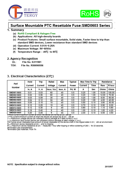
(a) RoHS Compliant & Halogen Free(b) Applications: All high-density boards(c) Product Features: Small surface mountable, Solid state, Faster time to trip thanstandard SMD devices, Lower resistance than standard SMD devices(d) Operation Current: 0.01A~0.20A(e) Maximum Voltage: 9V~60V DC(f) Temperature Range : -40℃to 85℃2. Agency RecognitionUL: File No. E211981TÜV: File No. R500905563. Electrical Characteristics (23℃)HI T=Trip current-minimum current at which the device will always trip at 23℃still air.V MAX=Maximum voltage device can withstand without damage at it rated current.(I MAX)I MAX= Maximum fault current device can withstand without damage at rated voltage (V MAX).Pd=Typical power dissipated-type amount of power dissipated by the device when in the tripped state in 23℃still air environment. R MIN=Minimum device resistance at 23℃prior to tripping.R1MAX=Maximum device resistance at 23℃measured 1 hour after tripping or reflow soldering of 260℃for 20 seconds. Termination pad characteristicsTermination pad materials:Pure Tin4. SMD Product Dimensions (Millimeters)5. Thermal Derating Curve6. Typical Time-To-Trip at 23℃7. Material SpecificationTerminal pad material: Pure TinSoldering characteristics: Meets EIA specification RS 186-9E, ANSI/J-std-002 Category 38. Part Numbering and Marking SystemPart Numbering System Part Marking SystemS M D □ □ □ – 0603Current RatingExampleWarning: -Operation beyond the specified maximum ratings or improper use may result in damage and possibleelectrical arcing and/or flame.-PPTC device are intended for occasional overcurrent protection. Application for repeated overcurrent condition and/or prolonged trip are not anticipated. 甲、 -Avoid contact of PPTC device with chemical solvent. Prolonged contact will damage the deviceperformance.AB=C=D=E=F=G=H=I= X=Y=Z=A=B=F=G==SMD001-0603SMD002-0603SMD003-0603SMD004-0603SMD005-0603SMD010-0603SMD012-0603SMD016-0603SMD020-0603SMD001-0603SMD002-0603SMD003-0603SMD004-0603SMD005-0603SMD010-0603SMD012-0603SMD016-0603SMD020-06039. Pad Layouts 、Solder Reflow and Rework RecommendationsThe dimension in the table below provide the recommended pad layout for each SMD 0603 deviceNote 1: All temperatures refer to of the package,measured on the package body surface.Reflow Profile。
思默康产品选型说明书

温度湿度气体2015价格表德国标准 东方精神壓力照度及位移思默康自动化设备(上海)有限公司价格生效期始于2014年10月15日1.0版TRW1-Series (T)TRW2-Series (T)0…10V / 4…20mANTC / PT / NiTPS1-Series (T)0…10V / 4…20mANTC / PT / NiTOW1-Series (T)TOW2-Series (T)TDE1-Series (T_av)TDE2-Series (T_av)风管温度防凍开关TDE2-Series (T_fp)通用温度有源传感器TUU1-Series (T)0…10V / 4…20mA通用温度无源传感器TUU2-Series (T)HPS2-Series (H_cs) HPS2-Series (H_lg)GDI1-Series (VOC)0…10V湿度:0..10V温度:0..10V可选 NTC ; PT ; NiPDE1- Series (dP_r) PDI1- Series (V&T) PDE2- Series (dP) PPE1- Series ( PPE2- Series (LRC1-Series(L)10V / 4…20mA CRC8-series (L&M)照度:0...10V人体活动:ON/OFF MRW2-Series(M)asia pacific照度及位移传感器温度湿度气体壓力照度及位移价格生效期始于2014年10月15日价格表其他配件德国标准 东方精神asia pacific配件asia pacific安装套件思默康自動化設備(上海)有限公司上海市閔行區莘庄工業區春東路479號C-1廠房2樓電話: (+8621) 5176 0211傳真: (+8621) 5176 0213泰慕康传感器科技有限公司香港新界荃灣168德士古道德豐工業中心2座13/樓10-11室電話: (+852) 3468 8636傳真: (+852) 3621 0002网站: / 邮箱: info@ asia pacific声明该价格表中,对技术信息都进行了简化,并保持随时更新。
燃气具产品出口认证

燃气具产品出口认证贸邦国际认证检测中心是欧盟公告机构S&Q MART(Notified Body 2159)在华办事处,燃气具官方检测认证机构,在燃气具测试盒认证领域有着丰富的经验。
在中国,贸邦开展燃气具认证服务多年,帮助客户的产品轻松获得欧盟CE认证证书,顺利打入国家市场。
燃气具测试的常用标准产品描述北美标准欧盟标准产品描述澳洲标准户外烧烤炉ANSI Z21.58EN498/EN484户外烧烤炉AS 4557家用燃气具ANSI Z21.1CAN 1-1.1-M81EN30-1-1家用燃气具AS 4551户外特殊烤具ANSI Z21.89EN498(Ref.)便携式野炊灶具AS 2658便携式野炊灶具ANSI Z21.72BSEN 521(直接压力)建筑加热器AG 404建筑加热器ANSI Z83.7EN461(Ref.)户外燃气火炉AS 4558户外燃气火炉ANZI Z21.97CR97-003EN461(Ref.)庭院加热器AS 4565庭院加热器ANSI Z 83.26BSEN 14543家用热水器AS 4552家用热水器ANSI Z21.10.3EN26室内加热器AS 4553室内加热器ANSI Z21.11.2EN449与燃气产品相关的部件测试及认证产品描述北美标准欧盟标准手动阀ANSI Z21.15EN1106 EN126软管UL569EN1763-1 BS3212调压阀ANSI Z21.18UL144EN12864烤叉电机UL1026EN60335-2-6电磁兼容性FCC EN55014 EN61000食物接触部件FDACA prop 651935/2004/ECLFGB30&31表面涂层ASTM1613-99/E1645-0191/338/EEC。
网分等射频产品-RS_创远_艾法斯

代替品牌(上海创远和美国艾法斯)
型号
美国艾法斯 3251 3252 3253 3254
描述
参数
1、频率范围可选择:1 kHz - 3 GHz/8 GHz/13.2 GHz/26.5 GHz 2、分析带宽:30M,标配; 3、TOI:13dBm; 4、平均显示噪声电平:-145dBm。
美金公开价
信号分析仪
美国艾法斯 SGA-3 SGA-6
信号源
1、频率范围可选择: 3G,6G 2、相位噪声:1GHz -135dBc/hz(偏置20K); 3、 输出功率:最大25dBm 。
上海创远 T5215A T5230A T5280A
网络分析仪
1、频率范围可选择:1.5G、3G、8G; 2、主要优点(卖点):一键式测试量解决方 案,提高生产效率; 3、主要优点(卖点):可选择中文界面操 作,对于操作者来说使用更加方便。
美金公开价
综合对比
性能指标稍微优于 安捷伦
R&S FSV
信号分析仪
R&S SMA100A
信号源
频率范围选择更灵 活,性能指标稍微 优于安捷伦
R&S ZVB
网络分析仪
R&S ZVL3
网络分析仪
R&S FSH6 R&S FSH18
2、
手持式仪表
对于手持表R&S的 更加轻便,可以测 试载噪比
R&S NRP系列 R&S NRP-B2 R&S NRP-B5
安捷伦
型号 描述 参数
1、频率范围可选择:3.0G、7.5G、13.6G、26.5G; 2、分析带宽:标配10M,选配25M,N9010可以到达 40M; 3、TOI:13dBm; 4、平均显示噪声电平:-161dBm。
自恢复保险丝SMD1210封装参数型号规格书大全
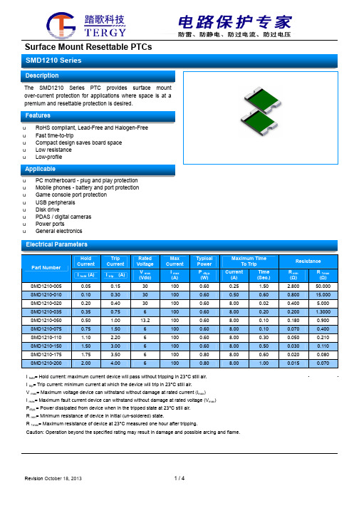
The SMD1210 Series PTC providessurfacemount over-current protection for applications where space is at a premium and resettable protection is desired.u RoHS compliant, Lead-Free and Halogen-Free u Fast time-to-tripu Compact design saves board space u Low resistance uLow-profileu Mobile phones - battery and port protection u Game console port protection u USB peripherals u Disk driveu PDAS / digital cameras u Power portsuGeneral electronicsHold Current Trip Current Rated Voltage Max Current Typical Power Maximum TimeTo Trip Resistance Part NumberI hold (A)I trip (A) V max (Vdc) I max (A) P dtyp. (W) Current (A) Time (Sec.) R min (Ω) R 1max (Ω) SMD1210-005 0.05 0.15 30 100 0.60 0.25 1.50 2.800 50.000 SMD1210-010 0.10 0.30 30 100 0.60 0.50 0.60 0.800 15.000 SMD1210-020 0.20 0.40 30 100 0.60 8.00 0.02 0.400 5.000 SMD1210-035 0.35 0.75 6 100 0.60 8.00 0.20 0.200 1.3000 SMD1210-050 0.50 1.00 13.2 100 0.60 8.00 0.10 0.180 0.900 SMD1210-075 0.75 1.50 6 100 0.60 8.00 0.10 0.070 0.400 SMD1210-110 1.10 2.20 6 100 0.60 8.00 0.30 0.050 0.210 SMD1210-150 1.50 3.00 6 100 0.60 8.00 0.50 0.030 0.110 SMD1210-175 1.75 3.50 6 100 0.80 8.00 0.60 0.020 0.080 SMD1210-2002.004.0061000.808.001.000.0150.070I hold = Hold current: maximum current device will pass without tripping in 23°C still air. I trip = Trip current: minimum current at which the device will trip in 23°C still air. V max = Maximum voltage device can withstand without damage at rated current (I max ) I max = Maximum fault current device can withstand without damage at rated voltage (V max ) P dtyp.= Power dissipated from device when in the tripped state at 23°C still air. R min = Minimum resistance of device in initial (un-soldered) state.R 1max = Maximum resistance of device at 23°C measured one hour after tripping.Caution: Operation beyond the speci fied rating may result in damage and possible arcing and flame.Profile FeaturePb-Free Assembly Average Ramp-Up Rate (T S max to T P ) 3°C/second max. Preheat :Temperature Min (T S min) Temperature Max (T S max) Time (T S min to T S max) 150°C 200°C60-180 seconds Time maintained above:Temperature(TL) Time (tL)217°C60-150 seconds Peak/Classification Temperature(T P ): 260°C Time within 5°C of actual peak: Temperature20-40 seconds Ramp-down Rate:6°C/ second max. Time 25°C to Peak Temperature8 minutes max.Note: All temperatures refer to of the package, measured on the package body surface.Solder reflowDue to “Lead Free ” nature, Temperature and Dwelling time for the soldering zone is higher than those for Regular. This may cause damage to other components.1.Recommended max past thickness > 0.25mm.2.Devices can be cleaned using standard methods and aqueous solvent.3.Rework use standard industry practices.4.Storage Environment : < 30/ 60%RH℃Caution:1.If reflow temperatures exceed the recommended profile, devices may not meet the performance requirements.2.Devices are not designed to be wave soldered to the bottom side of the board.Terminal pad material Pure TinSoldering CharacteristicsMeets EIA specification RS 186-9E, ANSI/J-std-002 Category 3holdA B C DeviceNominalNominal Nominal 1210 Series2.001.002.80Model -40℃-20℃0℃25℃ 40℃50℃60℃ 70℃ 85℃SMD1210-005 0.08 0.07 0.06 0.05 0.04 0.04 0.03 0.03 0.02 SMD1210-010 0.16 0.14 0.12 0.10 0.08 0.07 0.06 0.05 0.03 SMD1210-020 0.29 0.26 0.22 0.20 0.16 0.14 0.13 0.11 0.08 SMD1210-035 0.47 0.45 0.40 0.35 0.33 0.28 0.24 0.21 0.18 SMD1210-050 0.76 0.67 0.58 0.50 0.43 0.40 0.36 0.32 0.28 SMD1210-075 1.00 0.97 0.86 0.75 0.64 0.59 0.54 0.48 0.40 SMD1210-110 1.69 1.48 1.29 1.10 0.88 0.76 0.65 0.57 0.43 SMD1210-150 2.13 1.92 1.71 1.50 1.26 1.14 1.01 0.89 0.71 SMD1210-175 2.54 2.30 2.02 1.75 1.47 1.33 1.18 1.05 0.86 SMD1210-2002.902.632.312.001.681.521.351.200.98Maximum ambient operating temperature (Tmao) vs .hold current(I hold)u Operation beyond the specified maximum ratings or improper use may result in damage and possible electrical arcing and/or flame.u PPTC device are intended for occasional over-current protection. Application for repeated over-current condition and/or prolonged trip are not anticipated.uAvoid contact of PPTC device with chemical solvent. Prolonged contact will damage the device performance.0.33 (8.4)0.512(13.0)Arbor Hole DiameterDimensions are in inches (and millimeters)0.157 (4.0) 0.059 (1.5)Diameter Cover tape(4.0)(5.4)。
自恢复保险丝SMD0603封装参数型号规格书大全

The SMD0603 Series PTC providessurface mount over-currentprotection for applications where space is at a premium and resettable protection is desired.u RoHS compliant, Lead-Free and Halogen-Free u Fast time-to-tripu Compact design saves board space u Low resistance uLow-profileu Mobile phones - battery and port protection u Game console port protection u USB peripherals u Disk driveu PDAS / digital cameras u Power ports uGeneral electronicsHold Current Trip Current Rated Voltage Max Current Typical Power Maximum TimeTo Trip Resistance Part NumberI hold (A)I trip (A) V max (Vdc) I max (A) P dtyp. (W) Current (A) Time (Sec.) R min (Ω) R 1max (Ω) SMD0603-010 0.10 0.30 15 40 0.5 0.50 1.00 0.90 6.00 SMD0603-020 0.20 0.50 9.0 40 0.5 1.00 0.60 0.55 3.50 SMD0603-025 0.25 0.55 9.0 40 0.5 8.00 0.80 0.50 3.00 SMD0603-035 0.35 0.75 6.0 40 0.5 8.00 0.10 0.20 1.40 SMD0603-050 0.50 1.00 6.0 40 0.5 8.00 0.10 0.10 0.80 SMD0603-075 0.75 1.50 6.0 40 0.5 8.00 0.10 0.06 0.45 SMD0603-100 1.00 2.00 6.0 40 0.5 8.00 0.10 0.04 0.30I hold = Hold current: maximum current device will pass without tripping in 23°C still air. I trip = Trip current: minimum current at which the device will trip in 23°C still air. V max = Maximum voltage device can withstand without damage at rated current (I max ) I max = Maximum fault current device can withstand without damage at rated voltage (V max ) P dtyp.= Power dissipated from device when in the tripped state at 23°C still air. R min = Minimum resistance of device in initial (un-soldered) state.R 1max = Maximum resistance of device at 23°C measured one hour after tripping.Caution: Operation beyond the speci fied rating may result in damage and possible arcing and flame.Profile FeaturePb-Free Assembly Average Ramp-Up Rate (T S max to T P ) 3°C/second max. Preheat :Temperature Min (T S min) Temperature Max (T S max) Time (T S min to T S max)150°C 200°C60-180 seconds Time maintained above: Temperature(TL) Time (tL)217°C60-150 seconds Peak/Classification Temperature(T P ): 260°C Time within 5°C of actual peak: Temperature20-40 seconds Ramp-down Rate:6°C/ second max. Time 25°C to Peak Temperature8 minutes max.Note: All temperatures refer to of the package, measured on the package body surface.Solder reflowDue to “Lead Free ” nature, Temperature and Dwelling time for the soldering zone is higher than those for Regular. This may cause damage to other components.1. Recommended max past thickness > 0.25mm.2. Devices can be cleaned using standard methods and aqueous solvent.3. Rework use standard industry practices.4. Storage Environment : < 30/ 60%RH ℃Caution:1. If reflow temperatures exceed the recommended profile, devices may not meet the performance requirements.2. Devices are not designed to be wave soldered to the bottom side of the board.Terminal pad material Pure TinSoldering CharacteristicsMeets EIA specification RS 186-9E, ANSI/J-std-002 Category 3hold Ambient Temperature (°C)A B C DeviceNominalNominal Nominal 0603 Series1.000.701.00Model-40℃-20℃0℃25℃40℃50℃60℃70℃85℃SMD0603-010 0.13 0.12 0.11 0.10 0.08 0.07 0.06 0.05 0.03 SMD0603-020 0.27 0.25 0.23 0.20 0.17 0.14 0.12 0.10 0.07 SMD0603-025 0.32 0.29 0.27 0.25 0.21 0.18 0.16 0.05 0.03 SMD0603-035 0.47 0.41 0.38 0.35 0.29 0.26 0.24 0.20 0.14 SMD0603-050 0.67 0.59 0.54 0.50 0.41 0.37 0.34 0.29 0.20 SMD0603-075 0.98 0.85 0.81 0.75 0.60 0.54 0.44 0.40 0.31 SMD0603-1001.301.121.081.00 0.800.720.580.530.42Maximum ambient operating temperature(Tmao) vs. hold current (I hold)flame.u PPTC device are intended for occasional over-current protection. Application for repeated over-current condition and/or prolonged trip are not anticipated.uAvoid contact of PPTC device with chemical solvent. Prolonged contact will damage the device performance.0.33 (8.4)0.512(13.0)Arbor Hole DiameterDimensions are in inches (and millimeters)0.157 (4.0) 0.059 (1.5)Diameter Cover tape(4.0)(5.4)。
1812封装系列贴片保险丝

Performance SpecificationModel MarkingMaximumResistance V max I max I hold I trip P d Time To Trip@25°C@25°C Typ.CurrentTimeR iminR1max(V dc)(A)(A)(A)(W)(A)(Sec)(Ω)(Ω)JSMD1812-010JS/01030.01000.100.300.80.5 1.500.75015.000 JSMD1812-010/60JS/01060.01000.100.300.80.5 1.500.75015.000 JSMD1812-014JS/01460.01000.140.340.8 1.50.150.650 6.000 JSMD1812-020JS/02030.01000.200.400.88.00.020.350 5.000 JSMD1812-020/60JS/0260.01000.200.400.88.00.020.350 5.000 JSMD1812-030JS/03030.01000.300.600.88.00.100.250 3.000 JSMD1812-035JS/03530.01000.300.600.88.00.100.250 3.000 JSMD1812-035/60JS/0360.01000.300.600.88.00.100.250 3.000 JSMD1812-050JS/05016.01000.50 1.000.88.00.150.150 1.000 JSMD1812-050/30JS/05030.01000.50 1.000.88.00.150.150 1.000 JSMD1812-050/60JS/0560.01000.50 1.000.88.00.150.150 1.000 JSMD1812-075JS/07516.01000.75 1.500.88.00.200.0900.450 JSMD1812-075/24JS/07524.01000.75 1.500.88.00.200.0900.450 JSMD1812-075/33JS/0733.01000.75 1.500.88.00.200.0900.450 JSMD1812-110JS/1108.0100 1.10 2.200.88.00.300.0500.250 JSMD1812-110/12JS/11012.0100 1.10 2.200.88.00.300.0500.250 JSMD1812-110/16JS/11016.0100 1.10 2.200.88.00.300.0500.250 JSMD1812-110/24JS/1124.0100 1.10 2.200.88.00.300.0500.250JSMD1812-110/33JS11/3333.0100 1.10 2.200.88.00.300.0500.250JSMD1812-125JS/1258.0100 1.25 2.500.88.00.400.0500.140 JSMD1812-125/12JS/12512.0100 1.25 2.500.88.00.400.0500.140 JSMD1812-125/16JS/1216.0100 1.25 2.500.88.00.400.0500.140 JSMD1812-150JS/1508.0100 1.50 3.000.88.00.500.0400.160 JSMD1812-150/12JS/15012.0100 1.50 3.000.88.00.500.0400.160 JSMD1812-150/16JS/1516.0100 1.50 3.000.88.00.500.0400.160 JSMD1812-150/24JS/15024.0100 1.50 3.000.88.00.500.0400.160 JSMD1812-160JS/1608.0100 1.60 2.800.88.0 1.000.0300.130 JSMD1812-160/12JS/16012.0100 1.60 2.800.88.0 1.000.0300.130 JSMD1812-160/16JS/1616.0100 1.60 2.800.88.0 1.000.0300.130 JSMD1812-200JS/2008.0100 2.00 4.000.88.0 2.000.0200.100 JSMD1812-200/12JS/2012.0100 2.00 4.000.88.0 2.000.0200.100 JSMD1812-200/16JS/2016.0100 2.00 4.000.88.0 2.000.0200.100JSMD1812-250JS/2508.0100 2.50 5.000.88.0 5.000.0150.075 JSMD1812-250/12JS/2512.0100 2.50 5.000.88.0 5.000.0150.075JSMD1812-250/16JS25/1616.0100 2.50 5.000.88.0 5.000.0150.075JSMD1812-260JS/2608.0100 2.60 5.000.88.0 2.500.0150.050 JSMD1812-260/12JS/26012.0100 2.60 5.000.88.0 2.500.0150.050JSMD1812-260/16JS26/1616.0100 2.60 5.000.88.0 2.500.0150.050JSMD1812-300JS/30012.0100 3.00 5.000.88.0 4.000.0120.040 JSMD1812-300/8JS/30012.0100 3.00 5.000.88.0 4.000.0120.040V max=Maximum operating voltage device can withstand without damage at rated current(Imax).I max=Maximum fault current device can withstand without damage at rated voltage(Vmax).I hold=Hold Current.Maximum current device will not trip in25°C still air.I trip=Trip Current.Minimum current at which the device will always trip in25°C still air.Pd=Power dissipation when device is in the tripped state in25°C still air environment at rated voltage.Ri min/max=Minimum/Maximum device resistance prior to tripping at25°C.R1max=Maximum device resistance is measured one hour post reflow.CAUTION:Operation beyond the specified ratings may result in damage and possible arcing and flame. Environmental SpecificationsTest Conditions Resistance change Passive aging+85°C,1000hrs.±5%typicalHumidity aging+85°C,85%R.H.,168hours±5%typicalThermal shock+85°C to-40°C,20times±33%typical Resistance to solvent MIL-STD-202,Method215No changeVibration MIL-STD-202,Method201No changeAmbient operating conditions:-40°C to+85°CMaximum surface temperature of the device in the tripped state is125°CAgency Approval and Environmental CompliancAgency File Number Regulation StandardUL EN2174532002/95/ECTUV pending EN14582Thermal Derating CurveThermal Derading ChartRecommended Hold Current(A)at Ambient Temperature(°C)ModelAmbient Operation Temperature -40°C-20°C 0°C 25°C 40°C 50°C 60°C 70°C 85°C JSMD1812-0100.160.140.120.100.080.070.060.050.03JSMD1812-0140.230.190.170.140.120.100.090.080.06JSMD1812-0200.290.260.230.200.170.150.140.120.10JSMD1812-0300.440.390.350.300.260.230.210.180.15JSMD1812-0350.500.450.400.350.300.260.240.200.16JSMD1812-0500.590.570.550.500.450.430.350.300.23JSMD1812-0751.100.990.870.750.630.570.490.450.35JSMD1812-110 1.60 1.45 1.28 1.100.920.830.710.660.52JSMD1812-1252.00 1.75 1.52 1.25 1.000.950.900.750.53JSMD1812-150 2.30 2.05 1.77 1.50 1.23 1.090.950.820.61JSMD1812-160 2.10 1.96 1.88 1.60 1.26 1.120.980.840.63JSMD1812-200 2.88 2.61 2.25 2.00 1.80 1.66 1.45 1.090.80JSMD1812-2503.27 3.04 2.88 2.50 2.21 2.07 1.92 1.78 1.57JSMD1812-260 3.90 3.42 2.96 2.60 2.33 2.07 1.94 1.35 1.00JSMD1812-3004.153.763.463.002.552.282.011.611.33Average Time-Current CurveTemperature (°C)80604020-20-40160140120100806040200Derating Curves for JSMD1812SeriesTP20~40S TP260TL217Tsmaxt L60~150s200150tsPreheat60~180s25t25°C to peak TimeRamp-down TsminCritical ZoneTL to TPRamp-upASoldering ParametersProfile Feature Pb-Free AssemblyAverage Ramp-Up Rate(Ts max to T p)3℃/second mac.Preheat-Temperature Min(Ts min)-Temperature Max(Ts max)-Time(Ts min to Ts max)150℃200℃60~180secondsTime maintained above:-Temperature(TL)-Time(tL)217℃60~150secondsPeak Temperature(Tp)260℃Ramp-Down Rate6℃/second max.Time25℃to Peak Temperature8minutes maxStorage Condition0℃~35℃,≤70%RHRecommended reflow methods:IR,vapor phase oven,hot air oven,N2environment for lead-freeRecommended maximum paste thickness is0.25mmDevices can be cleaned using standard industry methods and solvents.Note1:All temperature refer to topside of the package,measured on the package body surface.Note2:If reflow temperatures exceed the recommended profile,devices may not meet the performance requirements. Physical Dimensions(mm.)ModelA B C D E Min.Max.Min.Max.Min.Max.Min.Min.JSMD1812-010 4.37 4.73 3.07 3.410.50 1.000.300.25 JSMD1812-010/60 4.37 4.73 3.07 3.410.50 1.000.300.25 JSMD1812-014 4.37 4.73 3.07 3.410.50 1.300.300.25 JSMD1812-020 4.37 4.73 3.07 3.410.50 1.300.300.25 JSMD1812-020/60 4.37 4.73 3.07 3.410.50 1.000.300.25 JSMD1812-030 4.37 4.73 3.07 3.410.50 1.300.300.25 JSMD1812-035 4.37 4.73 3.07 3.410.65 1.150.300.25 JSMD1812-035/60 4.37 4.73 3.07 3.41 1.00 1.500.300.25 JSMD1812-050 4.37 4.73 3.07 3.410.400.900.300.25 JSMD1812-050/30 4.37 4.73 3.07 3.410.400.900.300.25 JSMD1812-050/60 4.37 4.73 3.07 3.41 1.10 1.800.300.25 JSMD1812-075 4.37 4.73 3.07 3.410.400.900.300.25 JSMD1812-075/24 4.37 4.73 3.07 3.410.60 1.300.300.25 JSMD1812-075/33 4.37 4.73 3.07 3.410.60 1.300.300.25 JSMD1812-110 4.37 4.73 3.07 3.410.400.900.300.25 JSMD1812-110/12 4.37 4.73 3.07 3.410.400.900.300.25 JSMD1812-110/16 4.37 4.73 3.07 3.410.60 1.300.300.25 JSMD1812-110/24 4.37 4.73 3.07 3.410.60 1.300.300.25 JSMD1812-110/33 4.37 4.73 3.07 3.41 1.10 1.800.300.25 JSMD1812-125 4.37 4.73 3.07 3.410.60 1.300.300.25 JSMD1812-125/12 4.37 4.73 3.07 3.410.60 1.300.300.25 JSMD1812-125/16 4.37 4.73 3.07 3.410.65 1.150.300.25 JSMD1812-150 4.37 4.73 3.07 3.410.400.900.300.25 JSMD1812-150/12 4.37 4.73 3.07 3.410.350.850.300.25 JSMD1812-150/16 4.37 4.73 3.07 3.410.60 1.300.300.25 JSMD1812-150/24 4.37 4.73 3.07 3.410.40 1.200.300.25 JSMD1812-160 4.37 4.73 3.07 3.410.400.900.300.25 JSMD1812-160/12 4.37 4.73 3.07 3.410.350.850.300.25 JSMD1812-160/16 4.37 4.73 3.07 3.41 1.10 1.800.300.25 JSMD1812-200 4.37 4.73 3.07 3.410.60 1.300.300.25 JSMD1812-200/12 4.37 4.73 3.07 3.410.65 1.150.300.25 JSMD1812-200/16 4.37 4.73 3.07 3.41 1.10 1.800.300.25 JSMD1812-250 4.37 4.73 3.07 3.410.350.850.300.25 JSMD1812-250/12 4.37 4.73 3.07 3.410.65 1.150.300.25 JSMD1812-250/16 4.37 4.73 3.07 3.41 1.00 1.500.300.25 JSMD1812-260 4.37 4.73 3.07 3.410.50 1.300.300.25 JSMD1812-260/12 4.37 4.73 3.07 3.410.65 1.150.300.25 JSMD1812-260/16 4.37 4.73 3.07 3.41 1.00 1.500.300.25 JSMD1812-300 4.37 4.73 3.07 3.410.50 1.300.300.25 JSMD1812-300/8 4.37 4.73 3.07 3.41 1.00 1.500.300.25Termination Pad CharacteristicsTerminal pad materials:Tin-plated Nickel-CopperTerminal pad solder ability:Meets EIA specification RS186-9E and ANSI/J-STD-002Category3.Recommended Pad Layout(mm.)1.78士0.13.2士0.1Packaging QuantityPart Number QuantityJSMD035/60.050/60.110/33.150/24.250/16.260/16.300.300/81,000pcs/reelJSMD010.010/60.014.020.020/60.030.035.075/33.110/24.125.16.150.16.160/16.200/12.200/16.250/12.260/121,500pcs/reelThe others2,000pcs/reel Tape&reel packaging per EIA481-1Tape And Reel Specifications(mm)EIA Tape Component DimensionsEIA Reel DimensionsACover tapeCarrier tapeEmbossed cavityStorage And Handling‧Storage conditions:35°C max,70%R.H.‧Devices may not meet specified performanceif storage conditions are exceeded.P0W2(measured at hub)N(hub dia.)W1(measured at hub)1.78士0.13..2士.1EmbossmentTD P2Cover E1F WB B0K0E2T P1GoverningSpecifications EIA481-1W12±0.3P0 4.0±0.10P18.0±0.10P2 2.0±0.05A0 3.5±0.10B0 5.1±0.10B1max. 5.9D0 1.50+0.1,-0F 5.5±0.05E1 1.75±0.10E2min.10.25T0.6T1max.0.1K00.9±0.1Leader min.390Trailer min.160Reel DimensionsA max.178N min.60W112.4±0.5W218.4Part Number SystemJ SMD1812-口口口/口口Special voltage Rating(Optional)Holding Current RatingDevice Dimensions:Length/width(Unit:1/100inch)Size4532mm/1812inchJKSEMICross ReferenceJKSEMICrossReferenceTYCO/Raychem LittelfuseBourns/Multifuse®Polytronics/EVERFUSE®SEA-LANDJSMD1812-010miniSMDC010F1812L010MF-MSMF010SMD1812P010TF mSMD010 JSMD1812-010/60-1812L010/60-SMD1812P010TF/60mSMD010-60V JSMD1812-014miniSMDC014F1812L014MF-MSMF014SMD1812P014TF mSMD014 JSMD1812-020miniSMDC020F1812L020MF-MSMF020SMD1812P020TF mSMD020 JSMD1812-020/60-1812L020/60MF-MSMF020/60-mSMD020-60V JSMD1812-030miniSMDC030F-MF-MSMF030-mSMD030 JSMD1812-035-----JSMD1812-035/60---SMD1812P035TF/60-JSMD1812-050miniSMDC050F1812L050MF-MSMF050SMD1812P050TF mSMD050 JSMD1812-050/30-1812L050/30MF-MSMF050/30X SMD1812P050TF/30-JSMD1812-050/60-1812L050/60-SMD1812P050TF/60mSMD050-60V JSMD1812-075miniSMDC075F1812L075MF-MSMF075SMD1812P075TF mSMD075 JSMD1812-075/24miniSMDC075F/241812L075/24MF-MSMF075/24SMD1812P075TF/24mSMD075-24V JSMD1812-075/33miniSMDC075F/331812L075/33MF-MSMF075/33X SMD1812P075TF/33mSMD075-33V JSMD1812-110-1812L110MF-MSMF110SMD1812P110TF mSMD110 JSMD1812-110/12-1812L110---JSMD1812-110/16miniSMDC110F/161812L110/16MF-MSMF110/16SMD1812P110TF/16mSMD110-16V JSMD1812-110/24miniSMDC110F/241812L110/24MF-MSMF110/24X SMD1812P110TF/24mSMD110-24V JSMD1812-110/33-1812L110/33-SMD1812P110TF/33mSMD110-33V JSMD1812-125miniSMDC125F-MF-MSMF125-mSMD125 JSMD1812-125/12-----JSMD1812-125/16miniSMDC125F/161812L125/16-SMD1812P125TF/16-JSMD1812-260miniSMDC260F1812L260--mSMD260 JSMD1812-260/12miniSMDC260F/121812L260/12---JSMD1812-260/16miniSMDC260F/161812L260/16MF-MSMF260SMD1812P260TFT-JSMD1812-300miniSMDC300F1812L300-SMD1812P300TFT mSMD300 JSMD1812-300/8-----“Raychem”is a registered trademark of Tyco Electronics.“Littelfuse”is a registered trademark of Littelfuse“Multifuse”is a registered trademark of bourns,Inc.“EVERFUSE”is a registered trademark of Polytronics Technology Corp.“SEA-LAND”is a registered trademark of Sea-Land electronic corp.Website:For additional information,please contact your local SalesRepresentative.©Copyright2016,jksemiis a registered trademark of jksemi All rights arereserved。
维萨拉HUMICAP湿度温度传感器HMT120产品说明书

HMT120 Humidity and Temperature Transmitter12345678910111213 Vaisala HUMICAP® Humidity and Temperature Transmitter HMT120A Price Output parameters Humidity output only HHumidity and temperature output KHumidity and temperature, Catalytic sensor VTransmitter type Wall mount/fixed probe ARemote probe with 3 m cable BRemote probe with 5 m cable CRemote probe with 10 m cable DRemote probe with 10 m cable + 10 m extension ERemote probe with 20 m cable FDisplay No display0Display1Output signal 4...20 mA2-wire loop-powered AParameter for Output 1RH 0...100 %RH1Tdf-20...+80 °C(-4...+176 °F)2h-40...1500 kJ/kg(-9.5...+652.6 Btu/lb)3Tw0...+80 °C(+32...+176 °F)4a0...300 g/m3(0...131 gr/ft3)5x0...500 g/kg d.a.(0...3500 gr/lb)6Pw0...500 hPa(0...7.3 psi)7Pws0...500 hPa(0...7.3 psi)8Td -20...+80 °C(-4...+176 °F)9T -40...+60 °C(-40...+140 °F)B-20...+80 °C(-4...+176 °F)C0...+60 °C(+32...+140 °F)D-40...+80 °C(-40...+176 °F)E0...+50 °C(+32...+122 °F)FSPECIAL Define quantity ___________Scale___________XParameter for Output 2RH 0...100 %RH1None AT -40...+60 °C(-40...+140 °F)B-20...+80 °C(-4...+176 °F)C0...+60 °C(+32...+140 °F)D-40...+80 °C(-40...+176 °F)E0...+50 °C(+32...+122 °F)FSPECIAL Define quantity ___________Scale___________XDisplay Units Metric1Non metric2Sensor protection Plastic grid1Plastic grid with PTFE filter2Stainless steel sintered filter (for remote probes only)3Teflon sintered filter for HMP110DRW244938SP ETransmitter installation No accessories ARain shield with installation kit (215109)CInstallation kit for probe No accessories1Duct installation kit (215619)2Probe mounting flange (226061)3Outdoor installation: DTR504A Radiation Shield with probe installation kit (DTR504A)5Probe mounting clamp, 1 piece (225501)6Cable bushings Cable gland for 2...6 mm diameter cable AConduit fitting PG9BConduit fitting NPT 1/2"CNo bushing (rubber plug)DAll bushings (includes A, B, C and D)ZPC Accessories No0Service cable for PC, USB (219685)1 Operation manual No manual AMultilingual ZTotalQTYTotal value Selections in bold are included in the prices of the basic versionsSelections in italic are available at an extra costExample of order code with typical settingsHMT120K A0A1B11A1A0ZHMT120 Temperature Transmitter12345678910111213 Vaisala HUMICAP® Temperature Transmitter HMT120T A A Price Output parameters Temperature output only TTransmitter type Wall mount/fixed probe ARemote probe with 3 m cable BRemote probe with 5 m cable CRemote probe with 10 m cable DRemote probe with 10 m cable + 10 m extension ERemote probe with 20 m cable FDisplay No display0Display1Output signal 4...20 mA2-wire loop-powered AParameter for Output 1T -40...+60 °C(-40...+140 °F)B-20...+80 °C(-4...+176 °F)C0...+60 °C(+32...+140 °F)D-40...+80 °C(-40...+176 °F)E0...+50 °C(+32...+122 °F)FSPECIAL Quantity T Scale___________XParameter for Output 2None ADisplay Units Metric1Non metric2Sensor protection Plastic grid1Plastic grid with PTFE filter2Stainless steel sintered filter (for remote probes only)3Teflon sintered filter for HMP110DRW244938SP ETransmitter installation No accessories ARain shield with installation kit (215109)CInstallation kit for probe No accessories1Duct installation kit (215619)2Probe mounting flange (226061)3Outdoor installation: DTR504A Radiation Shield with probe installation kit (DTR504A)5Probe mounting clamp, 1 piece (225501)6Cable bushings Cable gland for 2...6 mm diameter cable AConduit fitting PG9BConduit fitting NPT 1/2"CNo bushing (rubber plug)DAll bushings (includes A, B, C and D)ZPC Accessories No0Service cable for PC, USB (219685)1 Operation manual No manual AMultilingual ZTotalQTYTotal value Selections in bold are included in the prices of the basic versionsSelections in italic are available at an extra costExample of order code with typical settingsHMT120T A0A B A11A1A0Z。
弱电编制说明及参数要求

弱电工程量清单编制说明及参数要求一、编制依据:1、本次清单依据《建设工程工程量清单计价规范》(GB50500-2008版)及甲方提供的图纸等进行编制。
二、编制事项说明:(一)审批中心及地下室1、宽带、专用及市话主干由室外引至电信设备间接线总箱管段不计,室外手孔井不计。
2、智能一卡通系统包括门禁系统及巡更系统、考勤系统、消费管理系统、发卡及管理中心,其中:门禁系统由于甲方需求尚未确定,设计图纸仅供参考,待甲方需求确定后,由专业智能电气公司进行深化设计;消费管理系统需要确定消费管理办公室后深化设计;考勤系统、发卡及管理中心图纸未涉及;故智能一卡通系统清单仅列入设备数量,管线暂计入暂定金考虑。
3、背景音乐系统清单仅列入机房设备,管线暂计入暂定金考虑。
4、有线电视系统可由甲方向当地有线电视台报装,暂计入暂列金额。
5、室外监控系统无具体平面图纸,暂计入暂列金额。
6、综合布线系统四、五层规划展示厅由装修公司进行设计,本预算仅预留配线架,数据主干及语言主干算至5F+1.5米。
7、地下室战时通讯交接箱系统部分战时安装,暂不放入计算。
8、机房间装修暂计入暂列金额。
9、县长热线系统暂计入暂列金额。
10、网上审批中心监控系统暂计入暂列金额。
(二)大会堂1、本清单梁高均暂定700mm。
2、弱电间二至三层竖向桥架规格不明,本清单按防火弱电桥架300*100及UPS 电源管SC32计入。
3、宽带、专用及市话主干由室外引至电信设备间接线总箱管段不计。
4、所有从弱电间、设备间出线均从出线处开始计算,并预留6米。
5、安全防范系统室外部份由于无设计平面图,暂列入暂列金额。
6、引自门卫室设备配线由引出处开始计算,并预算10米。
7、引自声控室扩声配线由引出处开始计算,并预算10米。
8、室外部分由于无设计图纸暂不计入。
9、背景音乐系统与消防广播共用,图纸仅设计系统图,所以清单仅列入机房设备。
10、舞台幕布系统、舞台灯光系统、舞台机械系统、内部通讯系统、视频影院系统、数字会议系统、扩声系统由于需要专业公司深化设计才能确定产品型号并施工,所以以上系统设备此次清单暂以预留金方式列入暂列金额,具体详见其他项目清单。
