威兰四通阀说明手册
Aventics IS12 5 2-方向控制阀门说明书

5/2-directional valve, Series IS12, size 2-ISO 5599-1-ISO 2-5/2-With air spring return With spring return With differential piston -single solenoid double solenoid -Qn = 2500 l/min-Compressed air connection output Base plate ISO 5599-1-Electrical connection Plug, M12, 3-pin -Manual override without detent with detentTypeSpool valve, positive overlapping Sealing principle Soft sealingBlocking principle Single base plate principle Connection type Plate connection StandardsISO 5599-1, ISO 2Working pressure min./max.See table below Control pressure min./max.See table below Ambient temperature min./max.Medium temperature min./max.MediumMax. particle sizeOil content of compressed air Nominal flow QnProtection class with connection LED status display Nominal resistance Duty cycle Typ. switch-on time Typ. switch-off time Mounting screwMounting screw tightening torque Weight0 ... 50 °C 0 ... 50 °C Compressed air 5 µm 0 ... 5 mg/m³2500 l/min IP65Yellow 1480 Ω100 %See table below See table below M 6 with hexagon socket 4 NmSee table belowPower consumptionNominal flow Qn at 6 bar and Δp = 1 bar, MO = Manual override1) according to ISO 5599-12) with air return3) With spring return4) 4 screws M4x40 DIN 912Your local contact:/contactus/EmersonAutomationSolutions/company/Emerson-Automation-SolutionsAn example configuration is depicted on the title page. The delivered product may thus vary from that in the illustration. Subject to change. This Document, as well as the data, specifications and other information set forth in it, are the exclusive property of AVENTICS GmbH. It may not be reproduced or given to third parties without its consent. Only use the AVENTICS products shown in industrial applications. Read the product documentation completely and carefully before using the product. Observe the applicable regulations and laws of the respective country. When integrating the product into applications, note the system manufacturer's specifications for safe use of the product. The data specified only serve to describe the product. No statements concerning a certain condition or suitability for a certain application can be derived from our information.The information given does not release the user from the obligation of own judgement and verification. It must be remembered that the products aresubject to a natural process of wear and aging.of the Emerson family of companies. All other marks are the property of their respective owners. © 2021 Emerson Electric Co.All rights reserved.2021-05。
威兰四通阀说明手册

INSTRUCTION MANUAL FOR SWITCH LIFT PLUG VALVE OPERATION提升式四通旋塞阀操作说明目录1.- 简介2.-手动模式和就地模式3.-自动模式3.1.自动控制系统描述3.2. -自动模式下限位销位置4.-自动模式1.- 简介此阀门操作时有三种模式:手动模式、就地模式、自动模式手动模式:通过执行机构上两个手轮来操作此阀门,但操作者必须熟悉此阀门的操作,在位置切换时,要求按预定程序来操作两个手轮。
这种模式是在执行机构失电的紧急情况下使用的,若旋塞到位后仍然转动手轮,会损坏阀门。
在手动模式下操作必须遵守以下步骤:z若控制盘没有电就把控制盘的开关钮打到关的位置。
z将每个执行器(电动头)的红色操作钮打到停止位置。
z用手轮操作时必须拉住离合杆,不然不动作。
就地模式:此模式下,操作者必须通过执行机构(电动头)上面的黑色旋钮来操作阀门,同时必须将限位销上到合适的位置。
例如:在就地模式下从A塔切换到B塔,首先要通过提升/回座执行器上的黑色旋钮来提升旋塞,等停止后,然后使用旋转执行器的黑色旋钮来旋转旋塞,等停止后,最后再用提升/回座执行器上的黑色旋钮来回座旋塞。
若在自动模式下,从A塔切换到B塔,只需按下控制盘上DRUM B键 (B塔)即可,控制盘会自动操作以上所有动作。
在就地模式下必须按以下步骤:z将控制盘开关键打到关的位置。
z将每个执行器(电动头)的红色操作旋钮打到就地模式位置。
自动模式:此模式下,控制盘自动来操作阀门。
它自动按程序控制两个执行器按一定顺序将旋塞从一个位置切到另一个位置。
有两种联锁(一种硬联锁,一种软联锁)防止旋塞回座后继续旋转,在自动模式下以下步骤必须遵守:z将旋塞切到A塔、B塔或旁路,必须将旋塞回座z通过执行器上的红色旋钮将执行器设在远控位置。
z根据需要将机械限位销放在合适位置。
z装上限位销。
2.- 手动模式和就地模式两种模式相近,但有两处不同:z就地模式下是用电动执行机构来操作阀门,手动模式使用手轮操作。
Parker Hannifin 3-Way和4-Way阀门操作说明说明书
FLUID CONTROL DIVISIONParker Hannifin Corporation95 Edgewood AvenueNew Britain, CT 06051Telephone (860) 827-2300IOM HN01Fax (860) 827-2384(Rev 0812)Installation, Operating & Maintenance Instructions3-Way and 4-Way, Pilot Operated, Sealed Spool Solenoid Valves1/4" NPT & 1/2" NPTValve Types: U331N03, U331N04, U341N03, U341N04, U341N05,U342N03, U347N03GENERAL SAFETY INSTRUCTIONS BEFORE INSTALLATIONFAILURE OR IMPROPER SELECTION OR IMPROPER USE OF THE PRODUCTS AND/OR SYSTEMS DESCRIBED HEREIN OR RELATED ITEMS CAN CAUSE DEATH, PERSONAL INJURY AND PROPERTY DAMAGE.Both the conduit coil and hazardous coil contain a green “grounding” wire that must be secured to a proper ground location. DO NOT cut off the green ground wire. Doing so could negate a proper ground path and leave the valve assembly unprotected or “hot”.This document and other information from Parker Hannifin Corporation, its subsidiaries and authorized distributors provide product and/or system options for further investigation by users having technical expertise. It is important that you analyze all aspects of your application, including consequences of any failure, and review the information concerning the product or system in the current product catalog. Due to the variety of operating conditions and applications for these products or systems, the user, through its own analysis and testing, is solely responsible for making the final selection of the products and systems and assuring that all performance, safety and warning requirements of the application are met. Usage of the device in a manner that is contrary to these Operating Instructions or the application conditions and specification providedin the Catalog is improper and will void your warranty.The products described herein, including without limitation, product features, specifications, designs, availability and pricing, are subject to change by Parker Hannifin Corporation and its subsidiaries at any time without notice.Carefully read installation, operation and maintenance procedures prior to installing or servicing valve.Do not use valve as a safety shut-off valve when making repairs.Do not install a valve or attempt to repair a valve before depressurizing system down to atmospheric pressure and removing electrical voltage.Care must be taken to ensure the proper use of the valve and that the valve materials selected are suitable for the media being handled. Parker assumes no liability for damage caused by improper material selection in the case of corrosion from aggressive media.Caution: Do not, at any time, make any alteration or modifications to any valve without the express and written approval of Parker’s Fluid Control Division.DescriptionThese valves are pilot operated 2-position, 4 ported 3-way or 5 ported 4-way, and 3-position 5 ported 4-way, directional control, solenoid models. They are offered in anodized aluminum body construction. Valves may be ordered with either DIN or Conduit NEMA 2, 4, 4X integrated coils for ordinary locations or NEMA 7 and 9 for hazardous locations:Applicable StandardsFM CSADivisions I; Class I, Groups A, B, C, D Divisions I; Class I, Groups A, B, C, DDivisions II; Class I, Groups E, F, and G Divisions II; Class I, Groups E, F, and GClass 1, Zone 1, AEx m II T4 Class 1, Zone 1, Ex m II T4The spool valves comprise a standard locking manual override providing operation without electrical supply.The spool valves are offered with the following standard features:-In line pilot for a low profile-22mm DIN pilot for direct mounting in non-explosive environments.-Both Conduit and Hazardous pilots for NEMA rated and explosive environments. Mounting plate required for NEMA rated coils.-High Nominal Flow-Cv 1.2 for 1/4” valves or 1250Nl/mn-Cv 3.0 for 1/2” valves or 3000Nl/mn-Standard Fluid temperature 14°F (-10°C) to 122°F (50°C)-Single Solenoid electrically operated, combined spring & pneumatic return (U331 & U341 series)-Dual Solenoid (Bistable) electrically operated, with neutral position return closed (U342 series)-Dual Solenoid (Bistable) electrically operated, air-solenoid return (U347 series)Principles of Operation – Connection of the NAMUR spool valve3-Way ValvesThe valve is piped to a single acting spring return cylinder as follows: Supply air pressure is applied at the inlet port 1. When de-energized, the valve inlet port 1 is closed and valve cylinder port 2 is open to the valve exhaust port 3. The cylinder is in the retracted state.When the coil is energized, pressure is applied from the valve inlet port 1 to the valve cylinder port 2 forcing the cylinder open and exhausting air behind the piston to the valve exhaust port 3. The cylinder is in the extended state.4-Way ValvesThe valve is piped to a double acting cylinder as follows: Supply air pressure is applied at the valve inlet port 1. Valve port 2 is open to one port of the cylinder while valve port 4 is open to the other port of the cylinder. The solenoid valve functions in such a way that pressure is applied to either side of the piston in the cylinder, and exhausted out of the opposite side of the pressurized cylinder.When de-energized, the supply air pressure port 1 is open to the valve port 2, valve port 4 is open to valve exhaust port 5, and valve exhaust port 3 is isolated by seals on the spool. The pilot valve orifice is sealed by the insert in the plunger. The pilot valve exhaust port is open to the valve piston assembly and atmosphere.When energized, the valve inlet port 1 is open to port 4, as well as between valve port 2 and valve exhaust port 3. The spool and seals seal valve exhaust port 5. This allows pressure to be applied to other side of the piston in the cylinder, causing the piston to move, and exhaust the fluid on the other side of the piston of the cylinder into port 2, through the valve and out of valve exhaust port 3.Manual OverridesManual override - The unit is shipped with a latching manual override. For a latching override, apply force to the slotted screw component, turn clockwise to lock. To unlock, turn counterclockwise.Fluid CodesListed below are the common fluid codes The codes for the approved fluids for use with each valve are printed on the outside of the individual packaging.CODE FLUIDA- Air or non-toxic, nonflammable gasesFor the maximum fluid temperatures, as well as valve ambient temperature limitations, check the valve part number on the nameplate and refer to the catalog.Installation InstructionsPrior to installing the solenoid valve, depressurize the pipes and clean them internally to avoid particles entering theMounting position and pressure limits:Valve with DIN Coil:Mount the valve directly on the actuator with the (2) M5 thread screws provided for the 1/4" valve and with the (2) M6 thread screws for the 1/2" valve. Torque to 35 to 45 in-lbs (4 to 5 Nm). Make sure the O-rings and locating pin are assembled to the bottom of the valve prior to mounting the valve for correct positioning on the actuator. Do not use the sleeve or enclosure as a lever when applying torque.Valve with Conduit or Hazardous Coil: (see next paragraph for valve model U341N05 only)The conduit and hazardous coils require the use of a mounting plate kit due to the increased coil width. The mounting plate kit consists of the aluminum mounting/spacer plate, 2 O-rings and 2 longer screws. The valve model number U341N05 containing the 3/2, 5/2 conversion plate does not require a separate mounting kit (see next paragraph). Make sure the O-rings are assembled to the bottom of the valve before positioning the valve over the mounting/spacer plate. Make sure that the O-rings and the locating pin are assembled to the bottom of the mounting/spacer plate prior to mounting the valve onto the actuator. Use the 2 longer screws to mount the valve to the actuator. Torque to 35 to 45 in-lbs (4 to 5 Nm). Do not use the sleeve or enclosure as a lever when applying torque.Valve model U341N05 with conversion plate:With the U341N05 valve, the 3/2, 5/2 conversion plate also functions as the mounting/spacer plate for the conduit and hazardous coils. Make sure that the gasket surface with the function indicator tab is assembled toward the bottom of the valve body. The indicator tab will point toward the schematic on the top of the valve body indicating the valve function. To change the valve function, rotate the conversion plate 180 degrees keeping the gasket face toward the vale body. The O-rings and the locating pin are assembled to the bottom of the conversion plate prior to mounting the valve onto the actuator. Use the 2 of the included screws to mount the valve to the actuator. Torque to 35 to 45 in-lbs (4 to 5 Nm). Do not use the sleeve or enclosure as a lever when applying torque.The valves are multi-poised and will perform properly when mounted in any position. However, for optimum life and performance, the valves should be mounted with the spool in the vertical position to minimize wear and reduce the possibility of foreign matter accumulating inside the sleeve and spool area.Line pressure must conform to nameplate rating.Valve Piping: Correctly support and align pipes to prevent mechanical strain on the valve. Connect line pressure to the inlet port. Use of tape sealant, thread compound or sealants is permissible, but should be applied sparingly to male pipe threads only. To avoid damage to the equipment, DO NOT OVERTIGHTEN pipe connections.Media filtration: Normally, filtration is not required, but dirt or foreign material in the media may cause excessive leakage, wear, or in exceptional cases, malfunction. The valves do include a 40 micron internal pilot filter to help prevent clogging of the pilot orifice. If additional filtration is used, install the filter on the inlet side as close to the valve as possible. Clean periodically depending on service conditions.Lubrication: Lubrication is not required.ELECTRICAL CONNECTIONSGeneral Recommendations and Safety Precautions- Electrical connection must be made by qualified personnel using standard electrical practices in compliance with local authorities and the National Electrical Code.- Depending on the voltage, electrical components must be grounded according to local standards and regulations- Most valves are designed for continuous duty. To prevent the risk of personal injury, do not touch the solenoid operator which can become hot under normal operating conditions.-The solenoid coil must be assembled to the valve sleeve operator for proper valve operation. Failure to assemble the coil to the valve before applying system voltage will permanently damage the coil within a short period of time.- Electrical supply must conform to nameplate rating.Hazardous Location Coil WARNING: Valves to be installed in Hazardous Locations, must be outfitted with Hazardous Location coils only. Verify nameplate data and coil part number before installing the valve.A surge protector corresponding to the coil’s rated current or a motor safety switch with instantenous short circuit or thermal cutout (set at rated current) has to be pre-connected for each solenoid coil as a short circuit cutout. The surge protector may be positioned in the respective power supply unit or it must be pre-connected separately.W ARNING:Turn off electrical power before connecting the valve to the power source.If the coil assembly is located in an inconvenient orientation, it may be reoriented to facilitate installation. Loosen coil assembly nut, rotate coil assembly in 45° increments to desired position, and then retighten the nut with an input torque of 4.0 to 5.0 in-lbs. [0,5 Nm].DIN Coil (ND1x) and various cable option terminations: Electrical connection is made with detachable DIN 43650 B plug connector for cable dia. 6-8mm (Pg9), rotatable by 180° increments (3 pins: 2 + earth ground pin). Loosen cable screw and remove plastic housing from DIN coil. Do not remove the gasket from the DIN spades on the coil. Separate the plastic block from the housing with a small screwdriver to expose the elecctrical terminations. Feed the lead wires through the conduit hub and attach them to the appropriate screw terminal. For electrical connection within the terminal box, use field wire that is rated for 90o C or greater. Snap the plastic block back into place inside the metal enclosure. Replace the cover and hand-tighten the cover screws. Place the gasket over the DIN spades on the coil and press the terminal box and coil together. Secure the terminal box to the coil using the mounting screw provided.Slide one o-ring over and down the sleeve assembly until the o-ring rests on the valve body., Slide the DIN coil over the valve sleeve. Affix nut to sleeve and tighten between 4.0 to 5.0 in-lbs. [0,5 Nm] torque.Conduit Coil (NC1x) with 1/2” NPT connection: Conduit coils meeting NEMA 2, 4, 4X integrated coils for ordinary locations. Use suitable electrical cabling and conduit materials and components meeting applicable NEMA recommendations.Hazardous Coil (NH1x) with 1/2” NPT connection: Hazardous coils meeting NEMA 7, and 9: Divisions I and II; Class I, Groups A, B, C, and D; Class II, Groups E, F, and G. Use suitable electrical cabling and conduit materials and components meeting applicable NEMA recommendations.Coil/enclosure temperature: Standard valves are supplied with coils designed for continuous duty service. Normal free space must be provided for proper ventilation. When the coil is energized continuously for long periods of time, the coil assembly will become hot. The coil is designed to operate permanently under these conditions. Any excessive heating will be indicated by smoking and/or odor of burning coil insulation.For the maximum valve ambient conditions, as well as the fluid temperatures, check the valve part number on the nameplate and refer to the catalog to determine the maximum temperatures.MAINTENANCEPrior any maintenance work, switch off power supply, depressurise and vent the valve to prevent the risk of personal∙Preventive maintenanceValve should be exercised (cycled from de-energized to energized position several times) if stored in inventory or if inactive for a lengthy period of time (more than a month).Avoid obstruction of exhaust port when it is not connected or protect it with a cap.∙CleaningMaintenance of the valve depends on the operating conditions. They must be cleaned at regular intervals. Cleaning must be done when a slowing down of the cycle, a leakage or an abnormal noise is noticed. The components must be checked for excessive wear.Note: Depending on service conditions, filtration, and lubrication, it may be required to periodically clean and/or replace worn components.C AUTION:Do not expose plastic or elastomeric materials to any type of commercial cleaning fluid. Parts should be cleaned with a mild soap and water solution.Monostable in line Miniature pilot Bistable Miniature pilot O-ring 10O-ring 9Screws 8Under Seat Flow Path 7Pin6“Bug”cap 5Operator Sleeve 4Manual Override 3O-ring11Pilot Top Plate 2Pilot Body 1DescriptionItemPilot ValveCross Section ViewConversion PlateHazardous or Conduit Coil U331N03, U331N04 13551331524 3154 2Trouble ShootingSymptom Procedure 1. Valve fails to operate or is sluggish. 1. Check electrical supply with voltmeter. Voltage must agreewith coil rating.2. Check coil with ohmmeter for shorted or open coil.3. Make sure that pressure complies with pressure ratingmarked on valve. Pressure must not be less than minimumoperating pressure.4. Inspect for contamination in ports. Remove debris if found.Check filter in main body, clean or replace if necessary.5. Verify that the sleeve assembly and plunger spring are notdamaged.* Remove the 4 screws and gently lift off the pilot sectionof the valve. Take care not to lose the o-rings andinternal components.* Remove the top plate. Lift out and inspect the sleeve,plunger, rubber disk and spring for debris or damage.Replace sleeve assembly, top plate and 4 screws.* Make sure the manual override stem is located on theported side of the valve body.2. External leakage at sleeve flange to body joint or pilot section to main body joint. 1. Check the 4 screws are tight but do not apply excessive forceto damage the plastic plate.2. If leakage persists, remove sleeve and check flange ando-ring seals for damage. Refer to step 5 above for disassembly.。
四通阀
电磁四通换向阀基础知识介绍内容提要:1、四通阀用途及特点;2、四通阀的工作原理3、四通阀结构;4、四通阀性能测试项目:5、四通阀使用注意事项;6、四通阀常见故障;7、四通阀工艺流程;8、四通阀重点工序照片。
四通阀结构(主阀):四通阀性能测试——气密性测试•测试条件:封闭E、C接口,从D、S接口向阀本体加2.9MPa(R22)、3.3MPa(R407C)、4.15MPa(R410A)的氮气或空气,将阀本体侵入水中保压1min,观察各部位有无气泡逸出。
测试设备:水检台四通阀性能测试——内泄漏测试•测试条件:在常温下,从阀体D接管口加0.98MPa的气压,封闭E、C接管口;在通电及不通电状态下,测量S接管口气体泄漏量。
测试设备:综合测试台四通阀性能测试——最低动作压力差•测试条件:在额定电压的85%,阀本体处于常温时,从阀本体D接口加表2第8项条件规定的额定气压,,封闭E、C接口,S接口与大气相通,确认阀的动作。
(特殊需要时,则从零开始缓慢地升高气压,测定阀换向时的气压值。
)测试设备:综合测试台四通阀性能测试——最高动作压差•测试条件:在额定电压的85%,阀本体处于常温时,从阀本体D接管口加2.45MPa(R22、R407C)、3.1MPa(R410A)的气压,封闭E、C接口,S接口与大气相通,确认阀的动作。
测试设备:综合测试台四通阀性能测试——最低动作电压•测试条件:施加2.45MPa(R22、R407C)、3.1MPa(R410A)气压,阀能正常、可靠换向的动作电压,应不大于额定电压的85%测试设备:综合测试台四通阀性能测试——绝缘电阻•测试条件:线圈放在常温水中浸泡24h后,在水中用DC500V兆欧表测定带电体与不带金属部件之间的绝缘电阻。
测试设备:直流低电阻测试仪四通阀性能测试——电气强度•测试条件:线圈放在常温水中浸泡24h后,在水中对带电体与不带电金属部件之间加上近似正弦波50HZ试验电压,漏电流不大于5mA,时间1min 。
四通阀维修手册
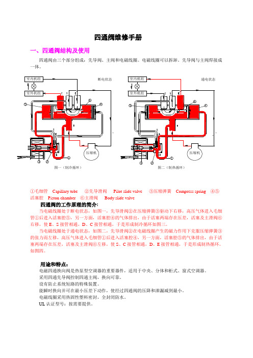
四通阀维修手册一、四通阀结构及使用能瞬时换向并可在最小压差下动作,使经过四通阀的压降和泄漏减到最小。
电磁线圈采用热固性塑料密封,全封闭防水。
UL认证型号:按需要提供。
环境温度:-20℃~55℃许可流体温度:-20℃~120℃环境相对湿度:小于95%二、空调系统中四通阀换向故障判别一)四通阀的结构特点1 中间流量由四通阀结构不难发现,当主滑阀处于中间位置状态时,如下图所示,E、S、C三条接管互相串通,有一定的中间流量,此时,压缩机高压管内的冷媒可以直接流回低压管。
设计中间流量的目的是当主滑阀处在中间位置时,能起到卸压的作用,避免空调系统受高压破坏。
2 压力差与流量的关系四通阀换向的基本条件是活塞两端的压力差(即排气管与吸气管的压力差)(F1-F2)必须大于摩擦阻力f ,否则,四通阀将不会换向。
换向所需的最低动作压力差(华鹭的实际水平低于1Kgf/cm2)是靠系统流量来保证的(如上图所示)。
当左右活塞腔的压力差(F1-F2)大于摩擦阻力f 时,四通阀换向开始,当主滑阀运动到中间位置时,四通阀的E、S、C三条接管相互导通,压缩机排出的冷媒一部份会从四通阀D接管直接经E、C接管流向S接管(压缩机回气口),形成瞬时串气状态。
此时,若压缩机排出的冷媒流量远大于四通阀的中间流量损失,高低压差不会有大的下降,四通阀有足够大的换向压力差使主滑阀到位;如果压缩机排出的冷媒流量不足时,因四通阀的中间流量损失会使高低压差有较大的下降,当高低压差小于四通阀换向所需的最低动作压力差时,主阀阀便停在中间位置,形成串气。
二)造成冷媒流量不足的可能原因1 空调系统发生外泄漏,造成系统冷媒循环量不足;2 天气很冷时,冷媒蒸发量不够;3 四通阀与系统匹配不佳,即所选四通阀中间流量大而系统能力小;4 空调机换向时间。
一般系统设计为压缩机停机一定时间后四通阀才换向,此时高低压趋于平衡,换向到中间位置便停止,即四通阀换向不到位,主滑阀停在中间位置,下次启动时,由于中间流量作用造成流量不足;5 压缩机启动时流量不足,变频机更明显。
四通阀的结构及使用、设计、选型、故障
四通阀的内部结构图如下:
由四通阀内部结构图可以看出主阀的换向滑块可定位在 三个位置: 最左端:此时排气端D与冷凝器端C相通、蒸发器端E与 吸气管端S相通,实现制冷过程; 中间位置:蒸发器端E、吸气管端S、冷凝器端C三条接管 相互通气,压缩机高压管内的冷媒可以直接流回低压管; 最右端:此时排气端D与蒸发器端E相通、冷凝器端C与吸 气管端S相通,实现制热过程。
四通阀的安装位置
不通电时弹簧不能使阀芯不能归位
主阀滑块下沉,出现漏气
线圈无法打螺钉
• 中山长虹常用的四通阀型号如下:
1P四通阀可选用型号如下:
序号 厂家 浙江三花 R22 佛山华鹭 常州兰柯 浙江春晖 R410A 浙江三花 浙江春晖 佛山华鹭 浙江三花 R407C 浙江春晖 佛山华鹭 名称 电磁四通阀 电磁四通阀 电磁四通阀 电磁四通阀 电磁四通阀 电磁四通阀 电磁四通阀 电磁四通阀 电磁四通阀 电磁四通阀 型号 SHF-4 STF-0101 DHF-2 DHF-5 SHF-4H-23U DHF-5-A STF-0101G SHF-4K-23U DHF-5-R STF-0101Z 线圈 SQ-601 STF-01AJ528AD1 DXQ-CH05-WX XQ-3 SQ-601 XQ-3 STF-01AJ528AD1 SQ-601 XQ-3 STF-01AJ528AD1
四通阀常见故障
• 四通阀常见的故障有:换向不良或不换向、串气。 • 换向不良或者不换向的原因: 1、线圈断线或电压不符合线圈性能规定,造成控制阀的阀芯不能动作。 2、由于外部原因,控制阀部分变形,造成阀芯不能动作。 3、由于外部原因,控制阀毛细管变形,流量不足,形成不了换向所需的压力差而 不能动作。 4、由于外部原因,主阀体变形,活塞被卡死而不能动作。 5、系统内的杂物进入四通阀内卡死活塞或主滑阀而不能动作。 6、钎焊配管时,主阀体的温度超过了120度,内部零件发生热变形而不能动作。 7、空调系统制冷剂泄漏,制冷剂不足,换向所需的压力差不能建立而不能动作。 8、压缩机的制冷剂循环量不能满足四通阀换向的必要流量。 9、变频压缩机转速频率低时,换向所需的必要流量得不到保证。 10、制冷系统产生液压冲击造成四通阀活塞被破坏而不能动作。
四通阀操作法
四通阀操作法一、启动控制面板:(1)控制面板在送电后即启动,这时控制面板上POWER ON 指示灯和部分阀状态指示灯会亮,表明四通阀和焦炭塔底进料阀处于电动状态。
如果需要可以手动操作四通阀或焦炭塔底进料阀。
手动操作时,压下电动执行机构上的手动操作柄,通过手轮的旋转方向控制四通阀的切换方向。
(2)四通阀正常生产切换操作,以塔T5101 A切换到塔T5101 B操作为例说明;(3)按工艺规程操作,保证待生产塔的预热温度达到切换条件;(4)按塔T5101 B底进料阀的OPEN按钮,现场确认焦炭塔底进料阀动作正确(阀杆向开阀方向运行);(5)当塔T5101 B底进料指示灯(VALVE OPEN)亮时,表示该阀已全开。
阀门停止。
(6)打开塔T5101 B底进料吹扫蒸汽阀进行吹扫进料线,吹扫2分钟,确认管线畅通后关闭(目测进料线上现场压力表无憋压现象)。
(7)按下控制面板上的DRUM A TO DRUM B按钮,四通阀开始切换。
这时必须密切注意辐射出口总线的压力指示,发现异常,立即按STOP按钮,然后根据情况按下RESTART,同时按下DRUM B TO DRUM A或DRUM A TO DRUM B按钮,将进料切回塔A或切到塔B;如果电动不能实现,立即手动切换四通阀。
(8)当切换到位后,控制面板上塔DRUM A指示灯熄灭、塔DRUM B指示灯亮;(9)打开塔A底进料吹扫蒸汽吹扫30分钟后,打开小吹汽阀,同时关闭塔A进料吹扫蒸汽阀。
然后按塔DRUM A底进料阀CLOSE按钮,现场确认阀门动作正确(阀门向关阀方向运行);(10)当塔DRUM A底料进阀的VALVE CLOSE指示灯亮,表示该阀全关。
(11)然后进行正常的冷焦作业,切换完成。
二、四通阀开工线的切换操作(1)由于正常生产时不需切换至开工线,因此,DRUM A , DRUM B与开工线之间的切换功能是被锁定的。
这时的状态是BYPASS OFF/ON锁的位置是指向OFF状态的。
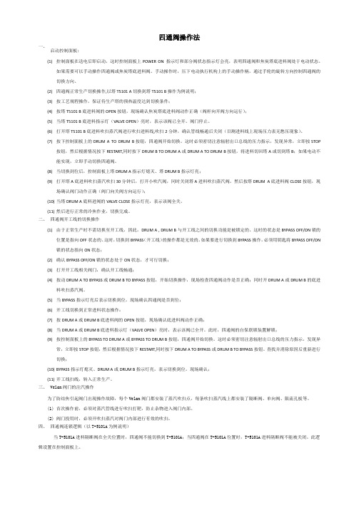
大容量四通换向阀结构及使用介绍
4、禁止线圈朝下安装,并保证线圈通风畅顺,避免日晒 雨淋,不允许主阀筒体竖直方向安装。
5、安全起见,四通阀安装时采用机吊方式,不允许采用 人工搬运方式。
6、阀体采用抱箍、托架方式固定时,必须加垫阻燃、耐 200℃以上的橡胶或其他较软的物体。
入阀体内各个部位。 15、总装整理时将线圈导线适当固定,并避免与系统高
温管路接触。 16、机组出厂前四通阀四接管焊接后应喷漆防锈。 17、工厂装配和现场检修时请登记筒体编号,便于追
溯。 18、机组高低压差过低时(低于最小换向压差),为避
免因四通阀切换不到位引起的质量事故,要求系统必须设 置必要的高低压和压差保护等措施。 19、定期检查并紧固法兰、线圈、导阀支架等固定螺 钉。 20、定期除尘,适当喷漆防锈。
结合以上分析,建议安装阀体时S接管朝下,D接管朝 上,以减少阀体形成干磨的几率。
2012-3-5
9
图4
2012-3-5
图6
图5
图7
10
使用、维护注意事项
1、四通阀存放时间超过2个月,应将主阀体颠倒过来放 置,以2个月为一个周期,建议在车间装配前将主阀体颠 倒过来放置4小时左右。
2、请采用铲车、吊车等设备搬运,防止投掷、跌落等冲 击。
2012-3-5
13
21、维修时先确认阀体内部气体压力低于0.05MPa, 线圈断电,沿对角方式缓慢逐个拧松法兰螺钉,待内部 气体慢慢排尽(否则将可能发生人身安全事故)后再全 部卸下螺钉和法兰。
22、拧紧导阀螺母时必须使用二把扳手同时进行拧 紧,防止导阀变形泄漏。
23、装卸法兰螺钉时采用扭力扳手,切忌用力过猛, 拧断螺钉、螺纹滑牙等。
VQC4000-TFP53 阀门操纵控制阀门手册说明书

Solenoid valve for actuator control: VQC4101R-5-X17 / VQC4301R-5-X17 VQC4401R-5-X17 / VQC4501R-5-X17(Basic and well-tried safety principles in accordance to ISO 13849)The intended use of the valve is to control the movement of an actuator.This product is validated according to ISO 13849 basic and well-tried safety principles. Refer to Doc. Nr. VQC4000-SMP0001.This manual contains essential information for the protection of users and others from possible injury and/or equipment damage.∙ Read this manual before using the product, to ensure correct handling, and read the manuals of related apparatus before use. ∙ Keep this manual in a safe place for future reference.∙ These instructions indicate the level of potential hazard by label of “DANGER”, “WARNING” or “CAUTION”, followed by important safety information which must be carefully followed.∙ To ensure safety of personnel and equipment the instructions in this manual and the product catalogue must be observed, along with other relevant safety practices.Take care about the compliance with the relevant safety laws and standards.Warning∙∙The compatibility of pneumatic equipment is the responsibility of the person who designs the pneumatic system or decides its specifications. Since the products specified here can be used in various operating conditions, their compatibility with the specific pneumatic system must be based on specifications or after analysis and/or tests to meet specific requirements.∙Only trained personnel should operate pneumatically operated machinery and equipment.Compressed air can be dangerous if an operator is unfamiliar with it. Assembly, handling or repair of pneumatic systems should be performed by trained and experienced personnel.∙Do not service machinery/equipment or attempt to remove components until safety is confirmed.1) Inspection and maintenance of machinery/equipment should only be performed after confirmation of safe locked-out control positions.2) When equipment is to be removed, confirm the safety process as mentioned above. Switch off air and electrical supplies and exhaust all residual compressed air in the system.3) Before machinery/equipment is re-started, ensure all safety measures to preventsudden movement of cylinders etc. (Supply air into the system gradually to create back pressure, i.e. incorporate a soft-start valve).∙Do not use this product outside of the specifications. Contact SMC if it is to be used in any of the following conditions:1) Conditions and environments beyond the given specifications, or if the product is to be used outdoors.2) Installations in conjunction with atomic energy, railway, air navigation, vehicles, medical equipment, food and beverage, recreation equipment, emergency stop circuits, press applications, or safety equipment.3) An application which has the possibility of having negative effects on people, property, or animals, requiring special safety analysis. ∙Effect of back pressure when using a manifoldThis valve is designed to be used on a manifold. This valve may experience back pressure due to pressure in the manifold exhaust ports. Back pressure check valves can be used to prevent back pressure affecting the outlet ports of this valve. ∙VentilationProvide ventilation when using a valve in a confined area, such as in a closed control panel. For example, install a ventilation opening, etc. in order to prevent pressure from increasing inside of the confined area and to release the heat generated by the valve. ∙Operation in a low temperature conditionIt is possible to operate a valve in extreme temperature, as low as –moisture etc. in low temperature.∙Do not disassemble the product or make any modificationsCaution∙ Ensure that the air supply system is filtered to 5 μm.2 SpecificationsNote 1)When the external pilot pressure is removed the main valve returns to the original position. The valves are to be used with a suitable manifold with external pilot supply or VQC4101-5-X10.Note 2)Values represented in this column are based on JIS 8375-1981 (operating with clean air and a supply pressure of 0,5 MPa equipped with light/surge voltage suppressor. Values vary depending on the pressure as well as the air quality.) Tested with ports size C8 and without back pressure check valves Note 3)Impact resistance: No malfunction occurred when it was tested with a drop tester in the axial direction and at right angles to the main valve & armature; in both energized & de-energised states and for every time in each condition (Values at the initial period.)Vibration resistance: No malfunction occurred in a one-sweep test between 45 and 2000 Hz. Tests are performed at both energized and de-energized states in the axial direction and at right angles to the main valve & armature. Note 4) If power supply is under -10% of standard power supply 24 V DC the valve may switch to the OFF position. The valve may switch to the de-energized state. 2.3 Symbol 2 position single3 position closed center3 position exhaust center3 position pressure centerFigure 32.4 Light/Surge Voltage SuppressorFigure 43 InstallationWarning3.1 Environment1. Do not use in an environment where the product is directly exposed to corrosive gases, chemicals, salt water, water or steam.2. Products with IP67 enclosures (based on IEC60529) are protected against dust and water, however, these products cannot be used in water.3. Incorrect mounting of the product violates the IP67 rating. Be sure to read the precautions of mounting for each product.4. Do not use in an explosive atmosphere.5.The product should not be exposed to prolonged sunlight. Use a protective cover.6. Do not mount the product in a location where it is subject to strong vibrations and/or shock. Check the product specifications.7. Do not mount the product in a location exposed to radiant heat.3.2 Piping1. Preparation before pipingBefore piping is connected, it should be thoroughly blown out with air (flushing) or washed to remove chips, cutting oil and other debris from inside the pipe.Install piping so that it does not apply pulling, pressing, bending or other forces the valve body. 2. Holding of pressureRubber sealed spool valves may have a slight leakage. This has to be taken into account for applications, in which the loss of pressure leads to a hazardous movement. 3. Maintenance space.The installation should have sufficient space for maintenance activities (removal of valve, etc.).4. Release of residual pressure.Provide a residual pressure release function for maintenance activities (removal of valve, etc.)Caution3.3 Lubrication∙ SMC products have been lubricated for life at manufacture, and do notrequire lubrication in service.∙ If a lubricant is used in the system, use turbine oil Class 1 (no additive),ISO VG32. Once lubricant is used in the system, lubrication must be continued because the original lubricant applied during manufacturing will be washed away.Warning3.4 Mounting1. Stop operation if air leakage increases and the equipment do not operate properly .Check mounting conditions after air and power supplies are connected. Initial function and leakage tests should be performed after installation.2. Instruction manual (this document)Install only after reading and understanding the safety instructions. Keep on file so that it can be referred to when necessary.3. CoatingWarnings or specifications indicated on the product should not be erased, removed, or covered up.Caution3.5 Wiring1. Applied voltage.When electric power is connected to the solenoid valve, be careful to apply the proper voltage. Improper voltage may cause malfunction or coil damage.2. Confirm the connections.After completing the wiring, confirm that the connections are made correctly.4 Settings4.1 Manual overrideWarningSince connected equipment will operate when the manual override isactivated, confirm that conditions are safe prior to activation. The non-locking push type (tool required) is fitted.Figure 5The manual override will pressurize the pilot actuator and cause the main valve to change state.ORIGINAL INSTRUCTIONSVQC 4101VQC 4301,4401,45014.2 Solenoid Valve Removal and Mounting (VQC4000)Figure 64.2.1 Removal steps1. Loosen the screws until they turn freely.2. Remove the solenoid valve by lifting the coil side of the valve. If pushing down on the screw is difficult, you can alternately press down on the valve gently in the area near the manual override.4.2.2 Mounting steps1. Push the valve down into place.2. Tighten the clamp screws with a tightening torque of 0.8 to 1.2 N ・mCautionDust on the sealing surface of the gasket or solenoid valve can cause air leakage.Take care that the pilot pressure is able to exhaust. Do not block the Exhaust Ports.Order Number VQC4101R-5-X17 2-position singleVQC4301R-5-X17 3-position closed center VQC4401R-5-X17 3-position exhaust center VQC4501R-5-X173-position pressure centerSpecial pilot valve cover (Color: Red)( Dimensions are in Millimeter )Special pilot valve cover (Color: Red)( Dimensions are in Millimeter )Figure 77 MaintenanceWarning1. Perform maintenance procedures shown in this instruction manual. If handled improperly malfunction or damage of machinery/equipment may occur.2. Removing the productTo avoid the risk of being burned, ensure that the valve has had sufficient time to cool before performing work.1. Shut off the fluid supply and release the fluid pressure in the system.2. In the case of air pilot or air-operated type, shut off the supply air source and discharge the compressed air inside the pilot piping.3. Shut off the power supply.4. Remove the product.3. Low frequency operation.Valves should be operated at least once every 30 days to prevent malfunction. (Use caution regarding the air supply).4. Manual overrideWhen the manual override is operated, connected equipment will be actuated.5. Do not disassemble the product.5.1 Replacing One-touch fittingsCautionCylinder port fittings are available with cassette type manifolds and are easily replaced. Fittings are secured with a retaining clip that is inserted vertically from either the top or bottom of the manifold. After removing the valve, remove the clip with a flat head screwdriver to replace the fittings. To mount a fitting, insert the fitting assembly until it spots and reinsert the retaining clip to its designated position.Figure 88 Limitations of UseAny use in an EN ISO 13849 system must be within the specified limits and application condition. The user is responsible for the specification, design, implementation, validation and maintenance of the safety system (SRP/CS).WarningIf a safe output from a safety relay or PLC is used to operate this valve, ensure that any output test pulse duration is shorter than 1 ms to avoid the valve solenoid responding.Figure 96 ContactsAUSTRIA (43) 2262 62280-0 LATVIA(371) 781 77 00 BELGIUM (32) 3 355 1464 LITHUANIA(370) 5 264 8126 BULGARIA (359) 2 974 4492 NETHERLANDS (31) 20 531 8888 CZECH REP . (420) 541 424 611 NORWAY (47) 67 12 90 20 DENMARK (45) 7025 2900 POLAND (48) 22 211 9600 ESTONIA (372) 651 0370 PORTUGAL (351) 21 471 1880 FINLAND (358) 207 513513 ROMANIA (40) 21 320 5111 FRANCE (33) 1 6476 1000 SLOVAKIA (421) 2 444 56725 GERMANY (49) 6103 4020 SLOVENIA (386) 73 885 412 GREECE (30) 210 271 7265 SPAIN (34) 945 184 100 HUNGARY (36) 23 511 390 SWEDEN(46) 8 603 1200 IRELAND (353) 1 403 9000 SWITZERLAND (41) 52 396 3131 ITALY (39) 02 92711 UNITED KINGDOM (44) 1908 563888SMC Corporation www.smcworld,com (Global) (Europe) SMC Corporation, Akihabara UDX15F, 4-14-1, Sotokanda, Chiyoda-ku, Tokyo 101-0021 JAPANSpecifications are subject to change without prior notice from the manufacturer. The descriptions of products in this document may be used by other companies. © 2012 SMC Corporation All Rights Reserved.。
柔性冷暖制冷系统的四通道柜式内部单元说明书
Manufacturer reserves the right to discontinue, or change at any time, specifications or designs without notice and without incurring obligations.© 2021 Carrier. All rights reserved.Edition Date: 08/21Form No: 40VMF-5ED Printed in U.S.A.Replaces: 40VMF-4ED1Engineering Data Book40VMF009A-048A4-Way Cassette Indoor Unit forVariable Refrigerant Flow (VRF) SystemsTABLE OF CONTENTS4-WAY CASSETTE BASIC INFORMATION (3)Specifications (3)Accessories (7)PIPING DIAGRAM (8)DIMENSIONS (9)WIRING DIAGRAM (10)ELECTRICAL CHARACTERISTICS (12)AIR THROW CHARTS (13)SOUND DATA (21)Sound Pressure Levels (21)NC Curves (22)CAPACITY DATA TABLES (24)234-WAY CASSETTE BASIC INFORMATION SpecificationsTable 1 —Data TableNOTES:*1.Rated per AHRI (Air Conditioning, Heating, and Refrigeration Institute) 1230 Standard Cooling: Indoor 80°F (27°C) db / 67°F (20°C) wb; Outdoor 95°F (35°C) db Heating: Indoor 70°F (21°C) db; Outdoor 47°F (8°C) db / 43°F (6°C) wb*2.These values are measured in anechoic chamber at a distance of 4.6 feet below the unit.MODEL40VMF009A--340VMF012A--3Power SupplyV/Ph/Hz 208/230-1-60Total Cooling Capacity *1Btu/h 9,00012,000Sensible Cooling Capacity *1Btu/h 8,62010,880Heating Capacity *1Btu/h 10,00013,500MCA A 0.730.91MOCP A15Panel / Grille40VMF001----Dimensions of Unit (H x W x D)in.9 x 33-1/8 x 33-1/8Dimensions of Panel / Grille (H x W x D)in.1-3/4 x 37-3/8 x 37-3/8Net Unit Weight lbs 54Net Panel / Grille Weight 1bs 13.2FilterDimensions L x H x D in.19-5/8 x 20-3-8 x 3/4Qty1 (Installed in Panel / Grille)Heat ExchangerInner Groove Copper Tube and Hydrophilic Aluminum finBlower / MotorFan Type Centrifugal Motor TypeDC motorAir Flow Rate (H/M/L)CFM 460/390/330560/460/390Sound Pressure Level (H/M/L)*2dBA 36.7/34.0/32.141.4/37.3/33.0Motor InputW 4054Min. External Static Pressure (Factory Setting)in. WG 0Max. External Static Pressure in. WG 0.12PipingConnections Gas (Low) Pressure in.1/2Liquid (High) Pressure in.1/4Condensatein.1-1/4Condensate Lift in.29-1/2Refrigerant Control Electronic Expansion Valve Connectable Outdoor Unit38VMH – Heat Pump 38VMR – Heat Recovery38VMH-1P – Single Phase Heat PumpWiringPower Wiring AWG Sized per NEC and Local Codes based on Nameplate Electrical DataControl WiringAWG2-core stranded shielded cable 18AWG4Table 2 —Data TableNOTES:*1.Rated per AHRI (Air Conditioning, Heating, and Refrigeration Institute) 1230 Standard Cooling: Indoor 80°F (27°C) db / 67°F (20°C) wb; Outdoor 95°F (35°C) db Heating: Indoor 70°F (21°C) db; Outdoor 47°F (8°C) db / 43°F (6°C) wb*2.These values are measured in anechoic chamber at a distance of 4.6 feet below the unit.MODEL40VMF015A--340VMF018A--3Power SupplyV/Ph/Hz 208/230-1-60Total Cooling Capacity *1Btu/h 15,00018,000Sensible Cooling Capacity *1Btu/h 13,37018,220Heating Capacity *1Btu/h 17,00021,000MCA A 1.12.0MOCP A15Panel / Grille40VMF001----Dimensions of Unit (H x W x D)in.9 x 33-1/8 x 33-1/811-3/4 x 33-1/8 x 33-1/8Dimensions of Panel / Grille (H x W x D)in.1-3/4 x 37-3/8 x 37-3/8Net Unit Weight lbs 54.069.0Net Panel / Grille Weight lbs 13.2FilterDimensions L x H x D in.19-5/8 x 20-3-8 x 3/4Qty1 (Installed in Panel / Grille)Heat ExchangerInner Groove Copper Tube and Hydrophilic Aluminum finBlower / MotorFan Type Centrifugal Motor TypeDC motorAir Flow Rate (H/M/L)CFM 680/560/4601000/700/610Sound Pressure Level (H/M/L)*2dBA 45.6/41.5/37.052.5/43.1/40.2Motor InputW 67153.5Min. External Static Pressure (Factory Setting)in. WG 0Max. External Static Pressurein. WG 0.12Piping connections Gas (Low) Pressurein.1/25/8Liquid (High) Pressure in.1/43/8Condensatein.1-1/4Condensate Lift in.29-1/2Refrigerant Control Electronic Expansion Valve Connectable Outdoor Unit38VMH – Heat Pump 38VMR – Heat Recovery38VMH-1P – Single Phase Heat PumpWiringPower Wiring AWG Sized per NEC and Local Codes based on Nameplate Electrical DataControl WiringAWG2-core stranded shielded cable 18AWG5Table 3 —Data TableNOTES:*1.Rated per AHRI (Air Conditioning, Heating, and Refrigeration Institute) 1230 Standard Cooling: Indoor 80°F (27°C) db / 67°F (20°C) wb; Outdoor 95°F (35°C) db Heating: Indoor 70°F (21°C) db; Outdoor 47°F (8°C) db / 43°F (6°C) wb*2.These values are measured in anechoic chamber at a distance of 4.6 feet below the unit.MODEL40VMF024A--340VMF030A--3Power SupplyV/Ph/Hz 208/230-1-60Total Cooling Capacity *1Btu/h 24,00030,000Sensible Cooling Capacity *1Btu/h 18,35022,330Heating Capacity *1Btu/h 27,00034,000MCA A 1.31.7MOCP A15Panel / Grille40VMF001----Dimensions of Unit (H x W x D)in.11-3/4 x 33-1/8 x 33-1/8Dimensions of Panel / Grille (H x W x D)in.1-3/4 x 37-3/8 x 37-3/8Net Unit Weight lbs 69.0Net Panel / Grille Weight lbs 13.2FilterDimensions L x H x D in.19-5/8 x 20-3-8 x 3/4Qty1 (Installed in Panel / Grille)Heat ExchangerInner Groove Copper Tube and Hydrophilic Aluminum finBlower / MotorFan Type Centrifugal Motor TypeDC motorAir Flow Rate (H/M/L)CFM 800/700/610950/800/680Sound Pressure Level (H/M/L)*2dBA 44.7/42.5/40.249.5/45.1/42.1Motor InputW 85.4131.7Min. External Static Pressure (Factory Setting)in. WG 0Max. External Static Pressurein. WG 0.12Piping connections Gas (Low) Pressurein.5/8Liquid (High) Pressure in.3/8Condensatein.1-1/4Condensate Lift in.29-1/2Refrigerant Control Electronic Expansion Valve Connectable Outdoor Unit38VMH – Heat Pump 38VMR – Heat Recovery38VMH-1P – Single Phase Heat PumpWiringPower Wiring AWG Sized per NEC and Local Codes based on Nameplate Electrical DataControl WiringAWG2-core stranded shielded cable 18AWG6Table 4 —Data TableNOTES:*1.Rated per AHRI (Air Conditioning, Heating, and Refrigeration Institute) 1230 Standard Cooling: Indoor 80°F (27°C) db / 67°F (20°C) wb; Outdoor 95°F (35°C) db Heating: Indoor 70°F (21°C) db; Outdoor 47°F (8°C) db / 43°F (6°C) wb*2.These values are measured in anechoic chamber at a distance of 4.6 feet below the unit.MODEL40VMF036A--340VMF048A--3Power SupplyV/Ph/Hz 208/230-1-60Total Cooling Capacity *1Btu/h 36,00048,000Sensible Cooling Capacity *1Btu/h 26,24032,390Heating Capacity *1Btu/h 40,00054,000MCA A 2.32.4MOCP A15Panel / Grille 40VMF001----FilterInstalled in Panel / Grille Dimensions of Unit (H x W x D)in.11-3/4 x 33-1/8 x 33-1/8Dimensions of Panel / Grille (H x W x D)in.1-3/4 x 37-3/8 x 37-3/8Net Unit Weight lbs 69.0Net Panel / Grille Weight lbs 13.2FilterDimensions L x H x D in.19-5/8 x 20-3-8 x 3/4Qty1 (Installed in Panel / Grille)Heat ExchangerInner Groove Copper Tube and Hydrophilic Aluminum finBlower / MotorFan Type Centrifugal Motor TypeDC motorAir Flow Rate (H/M/L)CFM 1100/950/8001200/1100/950Sound Pressure Level (H/M/L)*2dBA 53.9/50.4/47.355.4/54.0/50.5Motor InputW 182.7202.3Min. External Static Pressure (Factory Setting)in. WG 0Max. External Static Pressurein. WG 0.12Piping connections Gas (Low) Pressurein.5/8Liquid (High) Pressure in.3/8Condensatein.1-1/4Condensate Lift in.29-1/2Refrigerant Control Electronic Expansion Valve Connectable Outdoor Unit38VMH – Heat Pump 38VMR – Heat Recovery38VMH-1P – Single Phase Heat PumpWiringPower Wiring AWG Sized per NEC and Local Codes based on Nameplate Electrical DataControl WiringAWG2-core stranded shielded cable 18AWGAccessoriesTable 5 —Table of AccessoriesMDC – Multiport Distribution Controller78PIPING DIAGRAMFig. 1 —Piping Table 6 —PipingTable 7 —Gas/Liquid Line SizesNUMBERSYMBOL NAME1T1Room temperature sensor 2T2A Inlet pipe temperature sensor 3T2B Outlet pipe temperature sensor 4EEVElectronic expansion valveMODELGAS LIQUID 40VMF009A/012A/015A--31/21/440VMF018A/024A/030A/036A/48A--35/83/89DIMENSIONSNOTE: All dimensions are shown in inches.Fig. 2 —40VMF009A--3 to 40VMF048A--340VMF UNIT SIZEDIMENSION A009A 9012A 015A 018A 11-3/4024A 030A 036A 048A37-3/830-3/437-3/826-3/433-1/84-1/82-3/433-1/85-3/41-3/434-5/8 (Ceiling hole)Supply Air Duct KnockoutWiring Diagram Definitions and Settings (40VMF009A--3 to 40VMF048A--3)Table 8 —Code / TitleCODE TITLEFM Indoor Fan MotorT1Room Temperature Sensor T2A Inlet Pipe Temperature Sensor T2B Outlet Pipe Temperature Sensor ALARM Warning LampEEV Electronic Extension Valve XP1-8ConnectorsXS1-6XT1TerminalPUMP Pump MotorCS Condensate Switch GMSwing MotorTable 11 —SW1 Definition0 means auto addressing mode (Default)1 means factory test mode 0 means normal mode (Default)1 means factory self-checking mode (Reserved)Reserved0 means standard indoor unit (Default)1 means main indoor unit (must be addressed #63)Table 9 —ENC1 / ENC2ReservedReservedTable 10 —SW8 DefinitionReservedReservedTable 12 —0/1 DefinitionMeans 0Means 1Table 13 —Error Code / Contentdd Heating / Cooling ConflictE1Communication Error with Outdoor Unit E2Temperature Sensor (T1) Error E4Temperature Sensor (T2B) Error E5Temperature Sensor (T2A) Error E6DC Fan ErrorE7EEPROM Error (Data Storage)UU MDC Error in Auto System-Check Mode E9Communication Error with Wired Controller Eb EEV ErrorEC Indoor Fan Error in Auto System-Check Mode Ed Outdoor Unit Error EE Condensate ErrorFENo Address when Powered On for the First TimeELECTRICAL CHARACTERISTICSTable 14 —Electrical CharacteristicsMODELPOWER SUPPLY IFMHz VOLTS VOLTAGE RANGE MCA MOCP W FLA40VMF009A--360208/230V Max.253VMin.187V0.7315800.5940VMF012A--30.9115800.72 40VMF015A--3 1.1151700.81 40VMF018A--3 2.015170 1.60 40VMF024A--3 1.3151700.98 40VMF030A--3 1.715170 1.40 40VMF036A--3 2.315170 1.80 40VMF048A--3 2.415170 2.00SYMBOLS:MCA: Minimum Circuit Amps (A) MOCP: Maximum Over Current Protection (A) W: Fan Motor Rated Output (W)FLA: Full Load Amps (A)IFM: Indoor Fan MotorAIR THROW CHARTS40VMF009A--3Fig. 4 —Cooling VelocityFig. 5 —Heating Velocity40VMF012A--3Floor distance m(ft.)Fig. 6 —Cooling mode with 60°swingFig. 7 —Heating mode with 60°swing40VMF015A--3Fig. 8 —Cooling mode with 60°swingFig. 9 —Heating mode with 60°swing40VMF018A--3Fig. 10 —Cooling mode with 60°swingFig. 11 —Heating mode with 60°swing40VMF024A--3Fig. 12 —Cooling mode with 60°swingFig. 13 —Heating mode with 60°swingFig. 15 —Heating mode with 60°swingFig. 16 —Cooling mode with 60°swingFloor Distance m(ft.)Fig. 17 —Heating mode with 60°swingFig. 18 —Cooling mode with 60°swingFig. 19 —Heating mode with 60°swing21SOUND DATASound Pressure LevelsFig. 20 —Overall Sound Levels Table 15 —Cooling ModeNOTE: Units are in dBATable 16 —Heating ModeNOTE:Units are in dBAMODEL H M L 40VMF009A--336.734.032.140VMF012A--341.337.333.040VMF015A--345.241.536.940VMF018A--352.543.140.240VMF024A--344.642.540.240VMF030A--348.845.142.140VMF036A--353.450.047.340VMF048A--355.152.850.2MODEL H M L 40VMF009A--336.332.629.340VMF012A--341.436.532.640VMF015A--345.640.737.040VMF018A--352.842.739.440VMF024A--344.741.438.540VMF030A--348.944.741.440VMF036A--353.950.446.840VMF048A--355.154.050.522NC CurvesFig. 21 —40VMF009A--3Fig. 22 —40VMF012A--3Fig. 23 —40VMF015A--3Fig. 24 —40VMF018A--323NC Curves (Cont.)Fig. 25 —40VMF024A--3Fig. 26 —40VMF030A--3Fig. 27 —40VMF036A--3Fig. 28 —40VMF048A--3CAPACITY DATA TABLESTable 17 —Cooling CapacityModel Outdoorair temp.Indoor air temp.71 °FDB/59 °FWB73 °FDB/61 °FWB77 °FDB/64 °FWB80 °FDB/67 °FWB82 °FDB/68 °FWB86 °FDB/72 °FWB90 °FDB/75 °FWB968 8.2 8.1 8.7 8.5 9.2 9.0 9.8 9.3 10.0 9.7 10.7 9.7 11.2 10.1 73 8.2 8.1 8.7 8.5 9.2 9.0 9.8 9.3 10.0 9.7 10.7 9.7 11.2 10.0 77 8.1 8.1 8.7 8.5 9.2 8.9 9.7 9.2 9.9 9.6 10.5 9.6 11.0 9.9 82 8.1 8.0 8.5 8.4 9.0 8.9 9.5 9.1 9.7 9.5 10.3 9.5 10.8 9.9 86 8.1 8.0 8.4 8.4 8.9 8.8 9.4 9.0 9.6 9.4 10.2 9.4 10.6 9.8 91 7.9 7.9 8.2 8.2 8.7 8.7 9.2 8.9 9.3 9.3 9.9 9.2 10.4 9.6 95 7.8 7.8 8.1 8.1 8.6 8.6 9.0 8.8 9.2 9.2 9.7 9.1 10.2 9.5 100 7.7 7.7 8.0 8.0 8.4 8.4 8.8 8.8 9.0 9.0 9.5 9.1 9.9 9.4 104 7.6 7.6 7.8 7.8 8.2 8.2 8.6 8.6 8.8 8.8 9.3 9.0 9.7 9.3 110 7.4 7.4 7.6 7.6 7.9 7.9 8.4 8.4 8.5 8.5 9.1 8.8 9.4 9.11268 10.9 10.1 11.6 10.2 12.3 10.7 13.0 10.6 13.4 11.1 14.3 11.0 15.0 11.3 73 10.9 10.1 11.6 10.2 12.3 10.6 13.0 10.5 13.3 11.1 14.2 10.9 14.9 11.3 77 10.9 10.1 11.6 10.2 12.2 10.6 13.0 10.5 13.2 11.0 14.0 10.8 14.7 11.2 82 10.8 10.0 11.4 10.1 12.0 10.5 12.7 10.3 12.9 10.9 13.7 10.7 14.4 11.1 86 10.7 9.9 11.2 10.0 11.9 10.4 12.5 10.2 12.8 10.8 13.5 10.6 14.1 11.0 91 10.6 9.8 11.0 9.8 11.6 10.3 12.2 10.1 12.4 10.7 13.2 10.4 13.8 10.8 95 10.4 9.7 10.8 9.7 11.4 10.1 12.0 10.0 12.2 10.5 13.0 10.3 13.6 10.7 100 10.2 9.6 10.6 9.6 11.2 10.0 11.8 9.8 12.0 10.4 12.7 10.2 13.2 10.6 104 10.1 9.5 10.4 9.5 10.9 9.9 11.5 9.8 11.7 10.3 12.4 10.1 13.0 10.5 110 9.9 9.4 10.2 9.4 10.6 9.7 11.2 9.7 11.4 10.1 12.1 9.9 12.6 10.31568 13.6 12.4 14.5 12.6 15.4 13.1 16.3 13.0 16.7 13.7 17.8 13.5 18.7 13.9 73 13.6 12.4 14.5 12.5 15.4 13.0 16.3 12.9 16.7 13.6 17.8 13.4 18.7 13.8 77 13.6 12.3 14.5 12.5 15.3 13.0 16.2 12.9 16.6 13.5 17.5 13.3 18.4 13.7 82 13.5 12.3 14.2 12.4 15.1 12.9 15.9 12.7 16.2 13.4 17.1 13.2 18.0 13.6 86 13.4 12.2 14.0 12.3 14.9 12.8 15.6 12.6 16.0 13.2 16.9 13.0 17.7 13.5 91 13.2 12.1 13.7 12.0 14.6 12.7 15.3 12.4 15.6 13.1 16.5 12.8 17.3 13.2 95 13.0 12.0 13.5 11.9 14.3 12.4 15.0 12.3 15.3 12.9 16.2 12.7 17.0 13.1 100 12.8 11.8 13.3 11.8 14.0 12.3 14.7 12.1 14.9 12.8 15.8 12.6 16.5 13.0 104 12.6 11.7 13.0 11.7 13.7 12.2 14.4 12.0 14.6 12.6 15.5 12.4 16.2 12.8 110 12.4 11.6 12.7 11.6 13.3 12.0 14.0 11.9 14.2 12.4 15.1 12.2 15.7 12.61868 16.4 14.6 17.4 14.8 18.5 15.4 19.6 15.3 20.0 16.1 21.4 15.8 22.4 16.3 73 16.3 14.6 17.4 14.8 18.4 15.4 19.5 15.2 20.0 16.0 21.3 15.8 22.4 16.3 77 16.3 14.5 17.4 14.7 18.4 15.3 19.4 15.2 19.9 15.9 21.0 15.6 22.0 16.1 82 16.2 14.5 17.1 14.6 18.1 15.2 19.1 14.9 19.4 15.7 20.6 15.5 21.6 16.0 86 16.1 14.4 16.8 14.5 17.8 15.1 18.7 14.8 19.1 15.6 20.3 15.3 21.2 15.8 91 15.9 14.2 16.5 14.2 17.5 14.9 18.4 14.7 18.7 15.4 19.8 15.1 20.7 15.5 95 15.6 14.1 16.2 14.1 17.1 14.6 18.0 14.5 18.3 15.2 19.5 14.9 20.4 15.4 100 15.4 13.9 16.0 13.9 16.7 14.5 17.6 14.2 17.9 15.0 19.0 14.8 19.8 15.2 104 15.1 13.8 15.6 13.8 16.4 14.4 17.3 14.1 17.6 14.9 18.7 14.6 19.4 15.1 110 14.9 13.7 15.2 13.6 15.9 14.1 16.8 14.0 17.1 14.6 18.2 14.4 18.8 14.82425TC : Total Cooling SC : Sensible Cooling2468 21.8 18.0 23.2 18.3 24.6 19.0 26.1 18.8 26.7 19.7 28.5 19.4 29.9 19.9 73 21.8 18.0 23.2 18.2 24.6 18.9 26.0 18.8 26.6 19.6 28.5 19.3 29.9 19.9 77 21.7 18.0 23.2 18.2 24.5 18.8 25.9 18.7 26.5 19.6 28.1 19.2 29.4 19.7 8221.6 17.9 22.7 18.1 24.1 18.7 25.4 18.4 25.8 19.3 27.4 19.0 28.7 19.5 86 21.5 17.8 22.4 17.9 23.8 18.6 25.0 18.2 25.5 19.1 27.1 18.8 28.3 19.3 91 21.2 17.6 21.9 17.5 23.3 18.4 24.5 18.1 24.9 18.9 26.5 18.5 27.6 19.0 95 20.8 17.4 21.6 17.4 22.8 18.0 24.0 17.9 24.4 18.6 26.0 18.3 27.2 18.8 100 20.5 17.2 21.3 17.2 22.3 17.9 23.5 17.5 23.9 18.4 25.3 18.1 26.4 18.6 104 20.2 17.1 20.8 17.0 21.8 17.7 23.0 17.4 23.4 18.2 24.9 18.0 25.9 18.4 110 19.9 16.9 20.3 16.8 21.2 17.3 22.4 17.2 22.8 17.9 24.2 17.6 25.1 18.1 3068 27.3 21.3 29.0 21.7 30.8 22.4 32.6 22.2 33.4 23.2 35.7 22.8 37.4 23.4 73 27.2 21.3 29.0 21.6 30.7 22.3 32.5 22.1 33.3 23.1 35.6 22.8 37.3 23.3 77 27.1 21.2 28.9 21.5 30.6 22.2 32.4 22.0 33.1 23.0 35.1 22.6 36.7 23.1 8227.0 21.2 28.4 21.4 30.1 22.1 31.8 21.7 32.3 22.7 34.3 22.4 35.9 22.9 86 26.8 21.0 28.0 21.2 29.7 21.9 31.2 21.5 31.9 22.5 33.9 22.1 35.4 22.7 91 26.4 20.8 27.4 20.8 29.1 21.7 30.6 21.3 31.1 22.3 33.1 21.7 34.6 22.3 95 26.0 20.6 27.0 20.6 28.5 21.3 30.0 21.1 30.5 21.9 32.5 21.5 34.0 22.1 100 25.6 20.4 26.6 20.4 27.9 21.1 29.4 20.7 29.9 21.7 31.7 21.3 33.0 21.8 104 25.2 20.2 26.0 20.1 27.3 20.9 28.8 20.5 29.3 21.4 31.1 21.1 32.4 21.6 110 24.8 20.0 25.4 19.9 26.5 20.5 28.0 20.3 28.5 21.0 30.3 20.7 31.4 21.2 3668 32.7 25.6 34.9 26.1 37.0 26.9 39.1 26.7 40.1 27.9 42.8 27.5 44.9 28.1 73 32.7 25.6 34.8 26.0 36.9 26.8 39.0 26.6 40.0 27.8 42.7 27.4 44.8 28.0 77 32.6 25.6 34.7 25.9 36.7 26.7 38.9 26.5 39.7 27.7 42.1 27.1 44.1 27.8 8232.5 25.5 34.1 25.7 36.1 26.6 38.2 26.1 38.8 27.3 41.1 26.9 43.1 27.5 86 32.2 25.3 33.6 25.5 35.7 26.3 37.4 25.9 38.3 27.1 40.7 26.7 42.4 27.3 91 31.7 25.0 32.9 25.0 34.9 26.1 36.7 25.6 37.3 26.8 39.7 26.2 41.5 26.8 95 31.2 24.8 32.4 24.7 34.2 25.6 36.0 25.4 36.6 26.3 39.0 25.9 40.8 26.5 100 30.8 24.5 31.9 24.5 33.5 25.3 35.3 24.9 35.9 26.1 38.0 25.7 39.6 26.3 104 30.3 24.3 31.2 24.2 32.8 25.1 34.6 24.7 35.2 25.8 37.3 25.4 38.9 26.0 110 29.8 24.0 30.5 24.0 31.8 24.6 33.6 24.4 34.2 25.3 36.3 24.9 37.7 25.5 4868 43.6 31.6 46.5 32.2 49.3 33.2 52.2 32.9 53.4 34.2 57.1 33.7 59.8 34.3 73 43.5 31.6 46.4 32.1 49.2 33.1 52.0 32.8 53.3 34.1 56.9 33.6 59.7 34.2 77 43.4 31.6 46.3 32.0 49.0 32.9 51.8 32.7 53.0 33.9 56.1 33.3 58.8 33.9 8243.3 31.5 45.5 31.8 48.2 32.7 50.9 32.2 51.7 33.5 54.8 33.0 57.5 33.6 86 43.0 31.2 44.9 31.5 47.5 32.4 49.9 31.9 51.0 33.2 54.2 32.7 56.6 33.3 91 42.3 30.9 43.9 30.9 46.6 32.1 49.0 31.6 49.8 32.8 52.9 32.1 55.3 32.7 95 41.7 30.6 43.2 30.6 45.6 31.5 48.0 31.3 48.8 32.2 52.0 31.8 54.4 32.4 100 41.0 30.3 42.6 30.3 44.7 31.2 47.0 30.7 47.8 31.9 50.7 31.5 52.8 32.0 104 40.3 30.0 41.6 30.0 43.7 30.9 46.1 30.4 46.9 31.6 49.7 31.2 51.8 31.7 11039.729.740.729.742.430.344.830.145.631.048.530.650.231.1ModelOutdoor air temp.Indoor air temp.71 °FDB/59 °FWB 73 °FDB/61 °FWB 77 °FDB/64 °FWB 80 °FDB/67 °FWB 82 °FDB/68 °FWB 86 °FDB/72 °FWB 90 °FDB/75 °FWBTable 18 —Heating CapacityModel Outdoor air temp.Indoor air temp.59 °DB70 °DB77 °DB81 °DBkbtu/h degF D.B TC TC TC TC95 5.9 6.4 6.1 5.8 14 6.9 7.4 7.1 6.8 23 8.0 8.4 8.1 7.5 32 9.1 9.4 8.4 7.5 37 9.7 10.0 8.4 7.5 43 10.3 10.0 8.4 7.5 47 10.7 10.0 8.4 7.5 50 11.2 10.0 8.4 7.5 55 11.6 10.0 8.4 7.5 60 11.6 10.0 8.4 7.5 65 11.6 10.0 8.4 7.5125 7.9 8.6 8.2 7.9 14 9.4 10.0 9.6 9.2 23 10.8 11.4 11.0 10.2 32 12.2 12.7 11.4 10.2 37 13.0 13.5 11.4 10.2 43 13.9 13.5 11.4 10.2 47 14.5 13.5 11.4 10.2 50 15.1 13.5 11.4 10.2 55 15.7 13.5 11.4 10.2 60 15.7 13.5 11.4 10.2 65 15.7 13.5 11.4 10.2155 9.9 10.9 10.4 9.9 14 11.8 12.6 12.1 11.6 23 13.6 14.3 13.8 12.8 32 15.4 16.0 14.3 12.8 37 16.4 17.0 14.3 12.8 43 17.5 17.0 14.3 12.8 47 18.3 17.0 14.3 12.8 50 19.0 17.0 14.3 12.8 55 19.7 17.0 14.3 12.8 60 19.7 17.0 14.3 12.8 65 19.7 17.0 14.3 12.8185 12.3 13.4 12.8 12.2 14 14.6 15.5 14.9 14.3 23 16.7 17.7 17.1 15.8 32 19.0 19.8 17.7 15.8 37 20.3 21.0 17.7 15.8 43 21.6 21.0 17.7 15.8 47 22.6 21.0 17.7 15.8 50 23.5 21.0 17.7 15.8 55 24.4 21.0 17.7 15.8 60 24.4 21.0 17.7 15.8 65 24.4 21.0 17.7 15.82627TC : Total Coolingkbtu/hdegF D.BTC TC TC TC 245 15.8 17.3 16.4 15.7 14 18.7 20.0 19.2 18.4 23 21.5 22.7 22.0 20.4 32 24.4 25.4 22.8 20.4 3726.1 27.0 22.8 20.4 43 27.8 27.0 22.8 20.4 47 29.0 27.0 22.8 20.4 50 30.2 27.0 22.8 20.4 55 31.3 27.0 22.8 20.4 60 31.3 27.0 22.8 20.4 65 31.3 27.0 22.8 20.4 305 19.9 21.8 20.7 19.8 14 23.6 25.2 24.2 23.1 23 27.1 28.6 27.7 25.7 32 30.8 32.0 28.7 25.7 3732.8 34.0 28.7 25.7 43 35.0 34.0 28.7 25.7 47 36.5 34.0 28.7 25.7 50 38.0 34.0 28.7 25.7 55 39.4 34.0 28.7 25.7 60 39.4 34.0 28.7 25.7 65 39.4 34.0 28.7 25.7 365 23.4 25.6 24.4 23.3 14 27.7 29.6 28.5 27.2 23 31.9 33.7 32.5 30.2 32 36.2 37.6 33.8 30.2 3738.6 40.0 33.8 30.2 43 41.2 40.0 33.8 30.2 47 43.0 40.0 33.8 30.2 50 44.7 40.0 33.8 30.2 55 46.4 40.0 33.8 30.2 60 46.4 40.0 33.8 30.2 65 46.4 40.0 33.8 30.2 485 31.6 34.5 32.9 31.4 14 37.4 40.0 38.4 36.8 23 43.0 45.5 43.9 40.7 32 48.9 50.8 45.6 40.7 3752.2 54.0 45.6 40.7 43 55.7 54.0 45.6 40.7 47 58.0 54.0 45.6 40.7 50 60.3 54.0 45.6 40.7 55 62.6 54.0 45.6 40.7 60 62.6 54.0 45.6 40.7 6562.654.045.640.7Model Outdoor air temp.Indoor air temp.59 °DB 70 °DB 77 °DB 81 °DBManufacturer reserves the right to discontinue, or change at any time, specifications or designs without notice and without incurring obligations.© 2021 Carrier. All rights reserved.Edition Date: 08/21Form No: 40VMF-5ED Printed in U.S.A.Replaces: 40VMF-4ED28。
AVENTICS NL4-SOV系列电动3 2方向阀门ATEX可选商品说明书
09.04.2019
Page 3 | AVENTICS
Dimensions
Dimensions
A1 = inputA2 = outputA3 = ventilation port 1) electrically operated
DDiimmeensniosnios ninsmm
A1 G 1/2
A2 G 1/2
09.04.2019
Page 2 | AVENTICS
Part No.
0821300933 0821300934 0821300937
Connector standard
ISO 6952 -
basic valve with electrical connector
pilot valve without coil pilot valve without coil
Manual override
with detent
Electrical connection Pilot valve
Plug, ISO 6952, form B Plug, ISO 6952, form B Plug, ISO 6952, form B Plug, ISO 6952, form B
Part No. 0821300932
Connector standard
ISO 6952
basic valve with electrical connector -
Reverse polarity protection Protected against polarity reversal
PDF creation date:
Operationalvoltage AC 60 Hz 230 V -
四通道直接作用和助动阀门的应用说明书
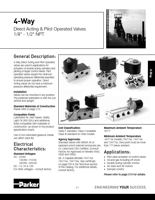
C1General Description:4-Way Direct Acting and Pilot Operated valves are used in applications foractuation of double acting cylinders and piloting of larger control valves. Pilot operated valves require the minimum operating pressure differential specified to ensure proper operation. Direct Acting valves do not have a minimum pressure differential requirement.InstallationValves can be mounted in any position. The preferred orientation is with the coil vertical and upright.Standard Materials of Construction Please refer to page C15.Compatible FluidsLubricated Air, Inert Gases, Water, Light Oil (300 SSU) and additional fluids compatible with materials of construction, as shown in the product specification charts.Use of non-lubricated gaseous media can affect valve life.ElectricalCharacteristics:Standard Voltages: AC – 24/60120/60–110/50 240/60–220/50DC – 12, 24 & 120For other voltages – consult factoryCoil Classification:Class F standard, Class H available Class B standard on V9xx models Agency Approvals:Standard valves with NEMA 4X orexplosion proof solenoid enclosures are UL Listed and CSA Certified. (Consult Factory for Approvals on Models V933, V935 and V955).SIL-3 Capable (Models 73417xx, 74417xx, 73477xx). See certificate on page F20 in the Technical section of this catalog. For additional details, consult factory.Maximum Ambient Temperature 167°FMinimum Ambient Temperature -40°F for models 73417xx, 74417xx and 73477xx. Dew point must be more than 7°F below ambient.Applications:• Pilot valve actuation of control valves • Oil and gas including off-shore • Double acting cylinder control • Air vises and Air motors •Damper controlPlease refer to page C15 for details.4-WayDirect Acting & Pilot Operated Valves 1/8" - 1/2" NPT4-WayC2Parker Hannifin Corporation Fluid Control Division180****8305(1800Valve05) /fcd43/83/160.75012524160NBR71417BN3SN0071417BN3SNR171417BN3SNM010C9 *Minimum ambient temperature: -40°F (-40°C). Dew point must be more than 7° F below ambient temperature.** Cv=0.45 with built-in metering control (Digits 11 and 12 are R1)3/83/160.75012524160NBR71477BN3SN0071477BN3SNR1-10C9 * Minimum ambient temperature: -40°F (-40°C). Dew point must be more than 7° F below ambient temperature.** Cv=0.45 with built-in metering control (Digits 11 and 12 are R1)C3Parker Hannifin CorporationFluid Control Division180****8305(1800Valve05)/fcd4-Way1/41/163/320.100.141/163/320.100.14010010130NBR V933LB2100V933LEF2100*C51/43/323/320.160.143/323/320.160.147510130NBRV933LB2075V933LEF2075*C51/41/163/320.100.141/161/80.080.180********NBR V935LB2100V935LEF2100*C51/43/323/320.160.143/321/80.140.217510130NBR V935LB2075V935LEF2075*C51/41/161/80.080.181/161/80.080.180********NBR V955LB2100V955LEF2100*C51/43/321/80.140.183/321/80.140.2107510130NBR V955LB2075V955LEF2075*C5Voltage 24/60120/60240/6012VDC 24VDC Coil CodeAB2A7W AB6A0Z AB8B6A DC1A3X DC2A4Y Coil Part Number*V57724F24V57731F24V57734F24V57727F24V57730F24*When ordering a replacement coil, use Coil Part Number (not Coil Code)Select the series V9 pressure vessel number from above and follow with the coil/enclosure number based on voltage from Fig. 1. Example V935LB2150 for 120/60 becomes part number V935LB2150AB6A0Z.*Fig. 1AC Power Consumption Rating VA Holding VA Inrush 17.532.5DC Power Consumption Rating 12 VDC 24 VDC 120 VDC 0.710.350.07C4Parker Hannifin CorporationFluid Control Division180****8305(1800Valve05)/fcd41/411/640.5530150 1.5150NBR 73477BN2KN0073477BN2KNM073477BN2KN7A 11C31/41/4 1.203015010167NBR 73477BN2PN0073477BN2PNM073477BN2PN7A 7C31/41/4 1.2030150 1.5150NBR 73477BN2PN0073477BN2PNM073477BN2PN7A11C31/41/4 1.20301500.6150NBR 73477BN2PN90--12C31/25/8 4.003015010167NBR 73477BN4UN0073477BN4UNM073477BN4UN7A 7C111/25/8 4.0030150 1.5150NBR 73477BN4UN0073477BN4UNM073477BN4UN7A11C111/25/84.00301500.6150NBR73477BN4UN90--12C111/411/640.5530150 1.5150NBR 73417BN2KN0073417BN2KNM073417BN2KN7A 11C11/41/4 1.203015010167NBR 73417BN2PN0073417BN2PNM073417BN2PN7A 7C11/41/4 1.2030150 1.5150NBR 73417BN2PN0073417BN2PNM073417BN2PN7A11C11/41/4 1.20301500.6150NBR 73417BN2PN90--12C11/25/8 4.003015010167NBR 73417BN4UN0073417BN4UNM0-7C101/25/8 4.0030150 1.5150NBR 73417BN4UN0073417BN4UNM0-11C101/25/84.00301500.6150NBR73417BN4UN90--12C10C5Parker Hannifin CorporationFluid Control Division180****8305(1800Valve05)/fcd4-Way1/411/640.5530150 1.5150NBR 73417VN2KN0073417VN2KNM073417VN2KN7A11C11/411/640.55301500.6150NBR 73417VN2KN90--12C11/41/4 1.203015010167NBR 73417VN2PN0073417VN2PNM073417VN2PN7A 7C11/41/41.20301501.5150NBR73417VN2PN0073417VN2PNM073417VN2PN7A11C11/41/41.201501.5150NBR74417BN2PN00--11C4* External pilot pressure to operate valve must be 30 - 150 psi.1/411/640.5530150 1.5150NBR 73477VN2KN0073477VN2KNM073477VN2KN7A11C31/411/640.55301500.6150NBR 73477VN2KN90--12C31/41/4 1.203015010167NBR 73477VN2PN0073477VN2PNM073477VN2PN7A 7C31/41/41.20301501.5150NBR73477VN2PN0073477VN2PNM073477VN2PN7A11C3C6Parker Hannifin CorporationFluid Control Division180****8305(1800Valve05)/fcd41/41/41.003015010167NBR73419AN2NN0073419AN2NNM0-7C21/411/640.550150 1.5150NBR 74417VN2KN00--11C41/41/4 1.20015010167NBR 74417VN2PN00--7C41/41/41.201501.5150NBR74417VN2PN00--11C4* External pilot pressure to operate valve must be 30 - 150 psi.C7Parker Hannifin CorporationFluid Control Division180****8305(1800Valve05)/fcd4-Way 2 position single solenoidPort identification:Press-1/Cyl - 2,4/ EXH - 3,54-Way 2 position single solenoidPort identification:Press-P/A-Cylinder/ EA-Exhaust/B-Cylinder/ EB- ExhaustC8Parker Hannifin Corporation Fluid Control Division180****8305(1800Valve05) /fcd42.59 Valve Reference C44-Way 2 position dual solenoidPort Identification:Press-1/CYL-2,4/EXH - 3,54-Way 2 position solenoidexternal pilotPort Identification:Press-1/CYL-2,4/EXH - 3,5C9Parker Hannifin CorporationFluid Control Division180****8305(1800Valve05)/fcd4-Way4-way direct actingV933xx: Normally Closed-Normally Closed v935xx: Normally Closed-Normally Open v955xx: Normally Open-Normally Open4-way 2 position single solenoid Port identification:pressure-1/cyl.A-2/cyl.B-4/exh.A-3/exh. B-5V933xx V935xx V955xxC10Parker Hannifin Corporation Fluid Control Division180****8305(1800Valve05) /fcd44-Way 2 position single solenoidPort identification:pressure-1/cyl.A-2/cyl.B-4/Exh.A-3/Exh. B-54-Way 2 position single solenoidPort identification:de-energized: pressure to AB to exhaustenergized: pressure to BA to exhaust4-Way4-Way 2 position single solenoidPort Identification:Press-1/CYL-2,4/EXH - 3,54-Way 2 position single solenoid4-Way 2 position dual solenoidPort Identification:Press-P/CYL-A,B/EXH - EC12Parker Hannifin CorporationFluid Control Division180****8305(1800Valve05)4-Way 2 position dual solenoid Port Identification:1-Pressure/2, 4-Cylinder/3, 5-Exhaust4-Way V933 Four-Way Normally Closed - Normally Closed ValvesWhen de-energized, both inlet portsare closed by the two plungerspreventing flow from the common inletthrough both of the valves. The cylindercommon exhaust, permitting flow fromthe cylinders to the exhaust. Whenthe coils are energized, both valveplungers rise, opening the inlet orifices,orifices in the sleeves. This stops flowfrom the cylinder ports to the exhaust,and permits flow from the inlet to thecylinder ports.The plungers of the two valves areat opposite positions in both theopen valve, through the sleeve, andout the cylinder port of the valve. At theexhaust. Therefore, fluid flows from theinlet of the valve to the cylinder port ofthe normally open valve and from thecylinder port of the normally closedvalve to the exhaust. When energized,the two valves reverse in position.Typical cylinder operation with V933 ValvesBoth coils de-energized. The inlet pressure is closed to both sides ofa double-acting cylinder. Side #1 and Side #2 of the cylinder are opento exhaust through cylinder ports #C1 and #C2. The piston can beCoil of valve #1 energized; coil of valve #2 de-energized. The inlet pressureis open to side #1 of the double-acting cylinder through cylinder port #C1,the exhaust is closed off by the plunger insert. Side #2 of the cylinder isopen to exhaust through cylinder port #C2, the inlet is closed off by theplunger insert. The piston moves to the right.Typical cylinder operation with V935 ValvesBoth coils de-energized. The inlet pressure is open to side #2 of the double-acting cylinder through cylinder port #C2 and the plunger insert closes off theexhaust. Side #1 of the cylinder is open to exhaust through cylinder port #C1and the inlet pressure is closed off. This causes the piston in the cylinder toBoth coils energized. The inlet pressure is open to side #1 of the cylinderthrough cylinder port #C1 and the exhaust is closed off. Side #2 of thecylinder is open to the exhaust through cylinder port #C2 and the inletpressure is closed off by the plunger insert. The piston moves to the right.4V955 Four-Way Normally Open - Normally Open ValvesBoth plungers are in the same positionwhen the coils are de-energized. Inthis condition, fluid flows through thecommon inlet of the body, up throughthe sleeves of both valves, and outthe cylinder ports of the valves. Bothorifices in the sleeve stops are closedto the exhaust ports by the plunger.In the energized position, both valveplungers operate together to closethe inlet ports, stopping flow into thevalve. At the same time, the orifices inthe sleeves are opened permitting flowfrom the cylinder ports to the commonexhaust port in the body.Typical cylinder operation with V955 ValvesBoth coils de-energized. The inlet pressure is open to both sides of thedouble-acting cylinder through cylinder port #C2 and the plunger insertcloses off the exhaust. Side #1 of the cylinder is open to exhaust throughcylinder port #C1 and the inlet pressure is closed off. This causes the pistonin the cylinder to move to the left.Coil of valve #1 energized; coil of valve #2 de-energized. The inletpressure is closed to side #1 of the double-acting cylinder and open toexhaust through cylinder port #C1. Side #2 of the cylinder is open tothe inlet pressure, through cylinder port #C2. The exhaust is closed offby the plunger insert. The piston moves to the left.4-Way Pilot Piped Materials of Construction**Product*WattTypePort SizeBodySleeve TubeSleeve Stop Sleeve Flange "Plunger Blank"Plunger Spring ShadingRingMax.AmbientTemp.73417AN 105/21/4Alum 304SS 430FR 430F 430FR 18-8SS Copper 167°F73417BN 105/21/4Brass 304SS 430FR 430F 430FR 18-8SS Copper 167°F 73417BN 105/21/2Brass 304SS 430FR 430F 430FR 18-8SS Copper 167°F 73417VN 105/21/4303304SS 430FR 430F 430FR 18-8SS Copper 167°F 73419AN 105/21/4Alum 304SS 430FR 430F 430FR 18-8SS Copper 167°F 7341LAN 105/21/8Alum 304SS 430FR 430F 430FR 301SS Copper 150°F 7341LMN 105/21/4Zinc 304SS 430FR 430F 430FR 301SS Copper 150°F 73477BN 105/21/4Brass 304SS 430FR 430F 430FR 18-8SS Copper 167°F 73477BN 105/21/4Brass 304SS 430FR 430F 430FR 18-8SS Copper 167°F 73477BN 105/21/2Brass 304SS 430FR 430F 430FR 18-8SS Copper 167°F 73477VN 105/21/4303304SS 430FR 430F 430FR 18-8SS Copper 167°F 74417BN 105/21/4Brass 304SS 430FR 430F 430FR 18-8SS Copper 167°F 04F48S2114/21/4Brass 305SS 430FR 430F 430FR 302SS Copper 77°F 04F48S211.54/21/4Brass305SS430FR430F430FR302SSCopper77°F* Shows first 4 or 7 digits of pressure vessel part number.** Maximum ambient temperature shown is the rating when valve is operating at the maximum fluid temperature as shown in the product sections for each of the valves in this catalog.4-Way Direct Acting Materials of Construction**Product*WattTypePort SizeBodySleeve TubeSleeve Stop Sleeve Flange "Plunger Blank"Plunger Spring ShadingRingMax.AmbientTemp.71417BN 244/21/4 - 3/8Brass 304SS 430FR 430F 430FR 18-8SS Copper 140°F 71477BN 244/21/4 - 3/8Brass 304SS 430FR 430F 430FR 18-8SS Copper 140°F V93320NC-NC 1/4Aluminum 304SS 430FR 430F 430FR 18-8SS Copper 122°F V93520NC-NO 1/4Aluminum 304SS 430FR 430F 430FR 18-8SS Copper 122°F V95520NC-NC1/4Aluminum304SS430FR430F430FR18-8SSCopper122°FC16Parker Hannifin CorporationFluid Control Division180****8305(1800Valve05)4NotesGeneral Description: The NAMUR mounting interface for direct mount pilot valves has become widely popular around the world. Parker's Direct Mount NAMUR valves meet that global need and are supplied with the necessary mounting hardware and seals as standard to ensure proper mounting, interface sealing and valve function. These valves can be converted between 3-way and 4-way operation by using Parker's patented mounting conversion plate which is unique in the industry. (See Conversion Plate Kit on P. C22)InstallationValves can be mounted in any position. The preferred orientation is with the coil vertical and uprightStandard Materials of ConstructionPlease refer to page C22. Compatible FluidsLubricated Air and Inert Gases.Use of non-lubricated gaseous media can affect valve life. Electrical Characteristics:Standard Voltages:AC – 24/60120/60–110/50240/60–220/50DC – 12, 24 & 120For other voltages – consult factory Coil Classification:Class F standardClass H availableAgency Approvals:Standard valves with NEMA Type 4Xor explosion proof solenoid enclosuresare UL Listed and CSA Certified. Foradditional details, consult factory.SIL-3 Capable (Models 73417xxx,73477xxx). See certificate on page F20in Technical Section of this catalog.Please refer to page C22 for details.Minimum Ambient Temperature-40° F (Dew point must be more than7° F below ambient temp.Maximum Ambient Temperature167° FApplications:• Pilot valve actuationof larger control valves• Oil and gas applications includingoff-shore installations• Double acting cylinder controlrequiring direct pilot mount valves• Air Vises• Air Motors• Damper ControlDirect Mount NAMUR 3/2, 3-Way — 5/2, 4-WayDirect Acting and Pilot Operated Valves 1/4" - 1/2" NPTC18Parker Hannifin CorporationFluid Control Division180****8305(1800Valve05)43/2 3-Way 2 Position-Single Solenoid-NAMUR Direct Mount - AluminumPort Size NPTOrifice Size in.Flow FactorCv Operating PressureDifferential(MOPD) PSIWatt Max. Fluid Temp. °F Seal Pressure VesselReferenceMin.Air Inert Gas Coil Valve 1/43/320.17015010167NBR71315AKDKN007C121/41/41.203015010167NBR73417BKDPN0073417BKDPNM073417BKDPN7A7C13* External pilot pressure to operate valve must be 30-150 PSI.43-Way Normally ClosedPort Identification:5/2, 4-Way 2 Position Single SolenoidPort Identification:5/2, 4-Way 2 Position Single SolenoidPort Identification:5/2, 4-Way 2 Position Dual SolenoidPort Identification:C22Parker Hannifin Corporation Fluid Control Division180****8305(1800Valve05) /fcd44-Way Pilot Direct Mount Materials of Construction**Product*Watt Type PortSize BodySleeveTubeSleeveStopSleeveFlange"PlungerBlank"PlungerSpringShadingRingMax.AmbientTemp. 71315AK103WNC NAMUR Alum304ss430FR430F430FR19-8SS Copper167°F 73417AK103/2-5/21/4Alum304SS430FR430F430FR18-8SS Copper167°F 73417BK103/2-5/21/4Brass304SS430FR430F430FR18-8SS Copper167°F 73417VK103/2-5/21/4Brass304SS430FR430F430FR18-8SS Copper167°F 73477AK103/2-5/21/4Alum304SS430FR430F430FR18-8SS Copper167°F 73477BK103/2-5/21/4Brass304SS430FR430F430FR18-8SS Copper167°F * Shows first 7 digits of pressure vessel part number.** Maximum ambient temperature shown is the rating when valve is operating at the maximum fluid temperature as shown in the product sections for each of the valves in this catalog.Parker’s 3-way/4-way Conversion Mounting Plate KitThis conversion mounting kit, unique in the industry, allows acommon valve to be installed and used in either a 3-way or4-way function.Available with U.S., or Metric mounting screws. Consult factoryfor the specific kit number that meets your requirements.。
RPEW4方向控制阀说明书
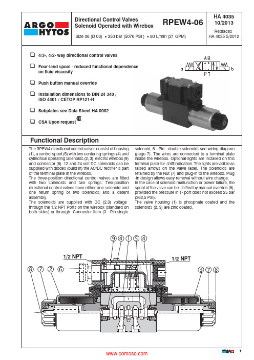
solenoid,5-Pin-double solenoid)see wiring diagram(page7).The wires are connected to a terminal plateinside the wirebox.Optional lights are installed on this12HA 4035RPEW4-06 /Spool Symbolssee the table spool symbolsValve Size06 (D 03)Solenoid OperatedDirectional Control Valves with WireboxNumber of Valve Positionstwo positions 2three positions3Type of Solenoid Coil for Wirebox (Plug-In-Coil)DC solenoid (DC-rectified)EW1DC solenoid with quenching diodeEW2Sealsno designation NBR V FPM (Viton)Orifice in P Port no designation without orifice D1Æ1,0 mm (0.039 inch)D2Æ1,5 mm(0.059 inch )D3Æ2,0 mm (0.079 inch)D4Æ2,2 mm (0.087 inch)D5Æ2,5 mm (0.098 inch)Manual Overrideno designationstandardN1covered with retaining nut N2covered with rubber bootWirebox Configurations:50Standard wiring box with 1/2 NPT both ends (Either side can be used for wiring, Removecover -plug accordingly)51Standard wiring box with 1/2 NPT both endsand LED diodes (B- side plugged,A - side covert for shipping)52Wiring box with 3 PIN connector ANSI/B93.55M mounted on A-side (B-side plugged, only for singlesolenoid valves)53Wiring box with 3 PIN connector ANSI/B93.55M mounted on B-side (A-side plugged, only for singlesolenoid valves)54Wiring box with 3 PIN connector ANSI/B93.55M mounted on A-side with LED diode (B-side plugged,only for single solenoid valves)55Wiring box with 3 PIN connector ANSI/B93.55M mounted on B-side with LED diode (A-side plugged,only for single solenoid valves)56Wiring box with 5 PIN connector ANSI/B93.55M mounted on A-side (B-side plugged, only for doublesolenoid valves)57Wiring box with 5 PIN connector ANSI/B93.55M mounted on B-side (A-side plugged, only for doublesolenoid valves)58Wiring box with 5 PIN connector ANSI/B93.55M mounted on A-side with LED diode (B-side plugged,only for double solenoid valves)59Wiring box with 5 PIN connector ANSI/B93.55M mounted on B-side with LED diode (A-side plugged,only for double solenoid valves)Type of Wirebox Wirebox for DCK Wirebox for AC (rectifier in wirebox)RSpool Speed Control Orificeno designation without damping T1orifice Æ0.7 mm (0.003 inch) in solenoidNote:For soft shift details / performancesee HA 4010Ordering CodeRated Supply Voltage of Wirebox (at the wirebox terminals)12 V DC / 2.64 A 0120024 V DC / 1.32 A 02400120 V AC / 60 Hz*12060*DC coils with rectifier in wireboxNote:For other voltages consult factoryCSA upon request 3HA 4035TypeSymbolCrossoverTypeSymbolCrossoverTechnical DataValve size mm (US)06 (D 03)Maximum flowL/min (GPM)see p-Q characteristicsMax. operating pressure at porte P, A, B bar (PSI)350 (5076)Max. operating pressure at port T bar (PSI)210 (3000)Pressure drop bar (PSI)see D p-Q characteristicsHydraulic fluidHydraulic oils of power classes (HL, HLP) to DIN 51 524Fluid temperature range for NBR seals °C (°F)-30 ... +80 (-22 ... +176)Fluid temperature range for FPM seals °C (°F)-20 ... +80 (-4 (176)Ambient temperature max.°C (°F)+50 (+122 )Viscosity rangemm 2/s (SUS)20 ... 400 (98 ... 1840)Maximum degree of fluid contamination Class 21/18/15 to ISO 4406Max. allowable voltage variation %DC:±10 / AC: ±10Max. switching frequency1/h 15 000Switching time, on: at n =32 mm 2/s (156 SUS)ms DC: 30 ... 50Switching time, off: at n =32 mm 2/s (156 SUS)ms DC: 10 (50)Duty cycle %100Service lifecycles107Enclosure type to EN 60 529IP 65Weigt - valve with 1 solenoid- valve with 2 solenoids kg (lbs)1,3 (2.9)1,9 (4.2)Mounting positionunrestrictedFunctional Symbols4HA 4035p-Q CharacteristicsMeasured at n = 32 mm 2/s (156 SUS)D p-Q CharacteristicsMeasured at n = 32 mm 2/s (156 SUS)Pressure drop D p related to flow rate.P r e s s u r e d r o p D p [b a r (P S I )]Flow Q [ L/min (GPM)]P-A P-B A-T B-T P-T Z112233C1155563H1122233P111133Y112222L212233B112233Z2123F111233R112233R212233A5122P5113Y5122C51234Z5123H5123F5123X112233N112233J152233J7522DCZ111C116H113P111Y112L215B118J151Z211DCH517F517X113N117X2510DCJ759F115R113R214A515P511Y512C516Z511Flow Q [ L/min (GPM)]O p e r a t i n g p r e s s u r e p [b a r (P S I )]19235105710466788Operating limits for maximum hydraulic power transferred by the directional valve. For respective spool type - see Functional Symbols.5678。
四尺水阀说明书
Close-off pressures are variable and actuator dependent, consult Select Pro and/or Price Guide for specifics.ApplicationThese valves are designed to meet the needs of HVAC and commercial applications requiring bubble tight shut-off for liquids. Typical applications include chiller isolation, cooling tower isolation, change-over systems, large air handler coil control, bypass and process control applications. The large Cv values provide for an economical control valve solution for larger flow applications. Designed for use in Victaulic® piping systems.Jobsite NoteValve assembly should be stored in a weather protected area prior toinstallation. Reference the butterfly valve installation instruction for additional information.PKA B C D E F 18.1” [460]16.1” [410]18.3” [464]15.4” [391]11.8” [300] 5.0” [127]F7100VIC Technical Data SheetPressure Enhanced Rubber SeatD a t e c r e a t e d , 02/27/2020 - S u b j e c t t o c h a n g e . © B e l i m o A i r c o n t r o l s (U S A ), I n c .PRB(X)A B C D E F 18.1” [460]16.1” [410]15.7” [400]12.9” [328]11.7” [297]5.0” [127]F7100VIC Technical Data SheetPressure Enhanced Rubber SeatD a t e c r e a t e d , 02/27/2020 - S u b j e c t t o c h a n g e . © B e l i m o A i r c o n t r o l s (U S A ), I n c .ApplicationPR Series valve actuators are designed with an integrated linkage and visualposition indicators. For outdoor applications, the installed valve must bemounted with the actuator at or above horizontal. For indoor applications theactuator can be in any location including directly under the valve.OperationThe PR series actuator provides 90° of rotation and a visual indicator shows theposition of the valve. The PR Series actuator uses a low power consumptionbrushless DC motor and is electronically protected against overload. A universalpower supply is furnished to connect supply voltage in the range of AC 24 (240)V and DC 24...125 V. Included is a smart heater with thermostat to eliminatecondensation. Two auxiliary switches are provided; one set at 10° open and theother is field adjustable. Running time is field adjustable from 30...120 secondsby using the Near Field Communication (NFC) app and a smart phone.†Use 60°C/75°C copper wire size range 12...28 AWG, stranded or solid. Useflexible metal conduit. Push the listed conduit fitting device over the actuator’scable to butt against the enclosure. Screw in conduit connector. Jacket theactuators input wiring with listed flexible conduit. Properly terminate the conduitin a suitable junction box. Rated impulse Voltage 4000 V. Type of action 1.Control pollution degree 3.PRXUP-MFT-T Technical Data SheetModulating, Non Fail-Safe, 24...240 V, NEMA 4X with BACnetDatecreated,7/1/22-Subjecttochange.©BelimoAircontrols(USA),Inc.Wiring DiagramsMeets cULus requirements without the need of an electrical ground connection.UP Universal Power Supply (UP) models can be supplied with 24 VAC up to240 VAC, or 24 VDC up to 240 VDC.Disconnect power.Provide overload protection and disconnect as required.Two built-in auxiliary switches (2x SPDT), for end position indication,interlock control, fan startup, etc.Only connect common to negative (-) leg of control circuits.46Actuators may be controlled in parallel. Current draw and inputimpedance must be observed.!WARNING! LIVE ELECTRICAL COMPONENTS!During installation, testing, servicing and troubleshooting of this product, it may be necessary to work with live electrical components. Have a qualified licensed electrician or other individual who has been properly trained in handling live electrical components perform these tasks. Failure to follow all electrical safety precautions when exposed to live electrical components could result in death or serious injury.PRXUP-MFT-T Technical Data SheetModulating, Non Fail-Safe, 24...240 V, NEMA 4X with BACnetD a t e c r e a t e d , 07/01/2020 - S u b j e c t t o c h a n g e . © B e l i m o A i r c o n t r o l s (U S A ), I n c .PRXUP-MFT-T Technical Data SheetModulating, Non Fail-Safe, 24...240 V, NEMA 4X with BACnetD a t e c r e a t e d , 07/01/2020 - S u b j e c t t o c h a n g e . © B e l i m o A i r c o n t r o l s (U S A ), I n c .。
W. E. Anderson 产品说明:Series WE06 V-Ball 螺纹钢阀门说明书
THE SERIES WE06 incorporates a V-port ball valve for impressive flow rates with minimal pressure drop. Quarter turn control ball valves are compact, lighter weight and much less expensive than comparable sized globe valves and segmented control valves. They also offer bubble tight shut off with zero leakage and can withstand high pressure drops. The 60° and 90° balls offer an equal percentage flow characteristic. W. E. Anderson’s V-port ball valves have been designed to offer maximum flow characteristics that are substantially higher than comparably sized globe valves. The natural flow pattern of ball valves increases flow rates and in many applications valves smaller than pipeline size can be used.Limit switches can be mounted directly to the valves allowing for remote position indication.The Series WE06 can be configured with an electric or pneumatic actuator. Electric actuators are available in weatherproof or explosion-proof, a variety of supply voltages and two-position or modulating control.Two-position actuators use the supply voltage to drive the valve open or close, while the modulating actuator accepts a 4 to 20 mA input for valve positioning. Actuators feature thermal overload protection and a permanently lubricated gear train.The pneumatic double acting actuator uses an air supply to drive the valve open and closed. The actuator has two supply ports with one driving the valve open and the other driving the valve closed. Spring return pneumatic actuators use the air supply to open the valve and internally loaded springs return the valve to the closed position. Also available is the SV3 solenoid valve to electrically switch the air supply pressure between the air supply ports for opening and closing the valve.FEATURES/BENEFITS• The 60° and 90° balls offer an equal percentage flow characteristic • Bubble tight shut off at high pressure drops• Limit switches can be mounted to manual valves for remote monitoring • Available with a variety of electric and pneumatic actuatorsSPECIFICATIONS VALVEWE06-DHD00-TWE06-DDA01-T WE06-DTD01-T-AWE06-DDA01-T-AA01WE06-CTI01-T-AV a l v e s , B a l l , A u t o m a t e dSERIES WE063-PIECE NPT STAINLESS STEEL V-BALL VALVEV-Port, Vented Ball, Electric or Pneumatic Actuators。
AVENTICS 5 2-方向阀门系列TC15商品说明书
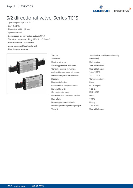
G 1/4
G 1/4
G 1/4
G 1/4
G 1/4
G 1/4
G 1/4
G 1/4
G 1/4
G 1/4
G 1/4
G 1/4
G 1/4
G 1/4
G 1/4
G 1/4
G 1/4
G 1/4
G 1/4
Compressed air connection Exhaust G 1/4 G 1/4 G 1/4 G 1/4 G 1/4 G 1/4 G 1/4 G 1/4 G 1/4 G 1/4
Version Activation Sealing principle Working pressure min./max. Control pressure min./max. Ambient temperature min./max. Medium temperature min./max. Medium Max. particle size Oil content of compressed air Nominal flow Qn Connector standard Protection class,with connection Duty cycle Mounting on manifold strip Mounting screw tightening torque Weight
PDF creation date:
03.03.2019
PDF creation date:
03.03.2019
Page 2 | AVENTICS
Technical data
Part No.
0820058001 0820058051 0820058026 R422103063 0820058076 R422103065 0820058501 R422103067 0820058551 R422103069
产品培训-四通阀PPT课件
内不清洁物质导入四通阀中,不
清洁物在芯铁与封头之间
5 线圈烧毁
6
线圈螺钉 拧断
不制热
(1)、客户接错电压
(2)、线圈本身短路
(1)、客户拧紧螺钉扭矩过大或动 作不规范
(2)螺钉或螺纹孔质量有问题
接入电压与铭牌上 一致 更换
更换或螺纹返工
-
15
V型改良四通换向阀简介
关于V型改良四通换向阀
总体结构无多大变化,仍由三部分组成:导阀、主阀、线圈,
❖ 当空调器设定在制热状态时,电磁线圈通电,芯铁吸上,使滑碗移 至右端(如图二),使b和c相通, d和a相通,使主阀左腔产生高 压,右腔产生低压,活塞在压差的作用下向右移动。此时,排气管 (D)与室内热交换器相通,吸气管(S)与室外热交换器相通,实 现制热循环。
-
3
四通换向阀的工作原理结构说明
-
4
3 最低动作 堵死E、C接管,S接管通大气,从D接 ≤85%额定
电压
管输入2.25MPa压力气体,给线圈施加 电压
50Hz交流电,测试阀能可靠动作时线
圈所需要的最低动作电压
-
7
四通换向阀主要性能项目和测试方法
4 内泄漏
5 气密性
6 线圈匝 间绝缘
7 线圈绝 缘电阻
堵死E、C接管,S接管通大气,从D接管 输入1.0MPa压力气体,测试线圈通断电状 态下的S接管管口的出气量
0.75 / 1.5
5/16
3/8
0.75 / 1.5
3/8
4/8
1.5~3
3/8
4/8
1.5~3
3/8
4/8
2~3
3/8
4/8
2~3
四通阀切断阀控制盘操作说明
四通阀、切断阀连锁控制盘操作说明
威兰四通阀和两边的切断阀通过控制盘实现连锁控制。
初次给控制盘供电时,首先要按一下控制盘上的复位(restart)按钮.
1当四通阀在开工线(Bypass)位置时,如果要将四通阀切换到生产塔A或B,A或B塔的切断阀必须打开,否则控制盘连锁无法切换。
2当四通阀在A或B塔工作时,A或B塔的切断阀为开,另一个塔的切断阀应该是关闭的位置,如果在A或B塔生产时,通过控制盘,相应的A或B塔的切断阀是不能关闭的。
3 当四通阀由A塔切换到B塔或由B塔切换到A塔,首先打开要切换到塔的切断阀,然后才能由A切换到B或由B切换到A,否则不能切换。
4 当四通阀由A或B塔切换到开工线(Bypass),控制盘上的钥匙要打到on (开)的位置,四通阀才能由A或B切换到开工线Bypass。
5 当发现切断阀,四通阀操作方向不正确,应立即按下相应的停(stop)按钮,当想继续操作该阀开或关,需要同时按下复位键(restart)和相应得方向按钮。
6当四通阀、切断阀完成切换操作时,电动头上面板转换旋钮打到停(Stop)的位置,当要进行下一次操作时,重新将电动头面板上的转换旋钮打到远传(Romote)状态。
当旋钮选择就地时(Local)远传不起作用,控制盘没有连锁功能。
不建议直接用就地操作来操作四通阀和两端的切断阀。
7当四通阀正式在A和B塔之间工作时,应把齿轮箱后面的两个铁销子(四通阀的机械限位)销上,此时四通阀只能在A和B塔之间切换,如果想将四通阀由A或B塔切换到开工线,需要拔下两个销子,将控制盘钥匙打到开(on)的位置才能进行切换操作
威兰公司北京代表处:孟繁国
2007.12.3。
- 1、下载文档前请自行甄别文档内容的完整性,平台不提供额外的编辑、内容补充、找答案等附加服务。
- 2、"仅部分预览"的文档,不可在线预览部分如存在完整性等问题,可反馈申请退款(可完整预览的文档不适用该条件!)。
- 3、如文档侵犯您的权益,请联系客服反馈,我们会尽快为您处理(人工客服工作时间:9:00-18:30)。
INSTRUCTION MANUAL FOR SWITCH LIFT PLUG VALVE OPERATION提升式四通旋塞阀操作说明目录1.- 简介2.-手动模式和就地模式3.-自动模式3.1.自动控制系统描述3.2. -自动模式下限位销位置4.-自动模式1.- 简介此阀门操作时有三种模式:手动模式、就地模式、自动模式手动模式:通过执行机构上两个手轮来操作此阀门,但操作者必须熟悉此阀门的操作,在位置切换时,要求按预定程序来操作两个手轮。
这种模式是在执行机构失电的紧急情况下使用的,若旋塞到位后仍然转动手轮,会损坏阀门。
在手动模式下操作必须遵守以下步骤:z若控制盘没有电就把控制盘的开关钮打到关的位置。
z将每个执行器(电动头)的红色操作钮打到停止位置。
z用手轮操作时必须拉住离合杆,不然不动作。
就地模式:此模式下,操作者必须通过执行机构(电动头)上面的黑色旋钮来操作阀门,同时必须将限位销上到合适的位置。
例如:在就地模式下从A塔切换到B塔,首先要通过提升/回座执行器上的黑色旋钮来提升旋塞,等停止后,然后使用旋转执行器的黑色旋钮来旋转旋塞,等停止后,最后再用提升/回座执行器上的黑色旋钮来回座旋塞。
若在自动模式下,从A塔切换到B塔,只需按下控制盘上DRUM B键 (B塔)即可,控制盘会自动操作以上所有动作。
在就地模式下必须按以下步骤:z将控制盘开关键打到关的位置。
z将每个执行器(电动头)的红色操作旋钮打到就地模式位置。
自动模式:此模式下,控制盘自动来操作阀门。
它自动按程序控制两个执行器按一定顺序将旋塞从一个位置切到另一个位置。
有两种联锁(一种硬联锁,一种软联锁)防止旋塞回座后继续旋转,在自动模式下以下步骤必须遵守:z将旋塞切到A塔、B塔或旁路,必须将旋塞回座z通过执行器上的红色旋钮将执行器设在远控位置。
z根据需要将机械限位销放在合适位置。
z装上限位销。
2.- 手动模式和就地模式两种模式相近,但有两处不同:z就地模式下是用电动执行机构来操作阀门,手动模式使用手轮操作。
z在手动模式下,操作者必须通过手轮控制旋塞的操作来提升和旋转,在就地模式下,执行器自动提升和回座。
在无控制盘的情况下,使用就地模式。
在这种模式下,必须改变旋转执行器的组态。
见“POYAM提升式四通旋塞阀控制盘启动和技术内容”。
在两种模式下,必须按同样方式调整限位销。
旋塞的位置从阀体上可以看出。
在手动和就地模式下必须使用粗的限位销(直径44mm)。
因阀门之间存在联锁,因此在就地模式下电动操作必须将执行器组态为联锁关闭,旋塞有三种基本的动作方式:z提升:旋塞被提升大约8mm,以保证可旋转。
z旋转:旋塞旋转直到止动盘碰到限位销为止,若只想转一点角度,使用电动头旋转时,可以用执行器上的红色旋钮来停止。
z回座:旋塞降低,用足够的力矩使旋塞被推入阀座。
注意:为防止损伤阀门密封面,永远不要在旋塞未提升时旋转。
A、B塔之间切换起始位置:限位销应在下图指示的①②位置a)提升旋塞b)旋转旋塞直到止动盘碰到限位销,此时止动盘上指针指示旋塞位置c)回座旋塞旁路B塔A塔起始位置:限位销应在下图指示的①②位置,止动盘指针指向A塔位置旁路B塔A塔a)移走①号位置的限位销b)提升旋塞c)旋转旋塞直到限位盘碰到②号限位销,此时止动盘指针指示旋塞的位置d)回座旋塞e)上紧①位置限位销,见下图:B塔A塔旁路起始位置:限位销应在下图的②位置,①号位置没有限位销,止动盘指针指向旁路位置a)提升旋塞b)旋转旋塞,直到止动盘超过A塔位置且①号位置可以插上限位销。
c)在①号位置上限位销,将旋塞向反方向旋转直到止动盘碰到①号限位销为止。
d)回座旋塞e)上紧①号限位销,见下图。
B塔A塔旁路从旁路切换到A塔后再切换到B塔起始位置:限位销应在上图指示的①②位置,止动盘指针应指向A塔位置a)提升旋塞b)旋转旋塞直到限位盘碰到②限位销c)回座旋塞d)上紧下图中①位置限位销,见下图。
B塔A塔旁路起始位置:限位销应在下图指示的①②位置,止动盘指针指向B塔位置 A塔B塔旁路a)移走②号位置的限位销b)提升旋塞c)旋转旋塞直到止动盘碰到①号限位销。
d)回座旋塞e)上紧②位置限位销,见下图:B塔A塔旁路起始位置:限位销应在下图的①位置,②号位置没有限位销,止动盘指针应指向旁路位置`B塔A塔旁路a)提升旋塞b)旋转旋塞,直到止动盘超过B塔位置。
c)在②号位置上限位销,将旋塞向反方向旋转直到止动盘碰到②号限位销为止。
d)回座旋塞e)上紧②号限位销,见下图。
B塔A塔旁路在中间位置停止旋塞当旋塞从A位置切向B位置或者从B位置切向A位置时,可以被停止在中间位置,当旋转执行器的显示屏显示50%时达到中间位置。
止动盘的指针会指向中间位置。
旋塞在中间位置停止后必须回座,重新从中间位置向A或B塔切换时,也必须重新提升。
3.-自动模式3.1. -自动模式简介当操作员操作阀门动作时,阀门必须有三个动作:z提升旋塞z旋转旋塞z回座旋塞控制盘自动按顺序控制两个执行器:提升/回座执行器和旋转执行器。
提升/回座执行器有一个提升限位开关,当提升至限位开关时,执行器停止提升。
回座时有一个力矩开关,当达到限制力矩时,回座自动停止来保证阀门的适当密封,同时不损害阀门。
旋转执行器也用限位开关来控制旋塞位置,出于安全考虑,必须使用限位销来限制旋塞的运动。
应用这种模式必须改变执行器的组态。
阀门出厂调整为这种模式。
见“POYAM提升式四通旋塞阀控制盘启动和技术内容”。
旋转执行器能够将旋塞停止在四个不同的位置,如下图所示:旁路中间位置B塔A塔旋塞旋转不能超过一圈,旁路位置是一圈的界限,是一圈的开始也是一圈的结束。
如果它从A塔切到旁路,它只能返回A塔的位置,不能从旁路切到B塔。
若旋塞从B塔切到旁路,它只能返回B塔的位置.通常阀门是在A塔和B塔之间切换,阀门也可以停在中间位置,但在中间位置时,阀体必须回座。
若旋塞不旋转时,它不能处于提升的状态,这一点由控制盘自动完成。
下图指示的是阀门所有的动作形式;A塔中间位置B塔旁路旁路控制盘有三种不同的操作模式Continuous mode连续模式:B到A或A到BMid mode中间模式:A到中间位置,中间位置到AB到中间位置,中间位置到BBypass mode旁路模式:A或B到旁路,旁路到A或B。
若起始位置是A,到旁路后它不可能继续到B,只能返回A;若起始位置是B,到旁路后,不可能继续到A,只能返回B。
3.2自动模式下限位销的位置出于安全考虑,在自动模式下必须使用限位销,限位销必须插在图一中的①②号位置,当在中间模式或连续模式操作时,必须移走销子才能将阀门切到旁路位置。
注意:若周围环境中有可燃气体,控制盘严禁打开。
只有切断控制盘电源后才能打开。
4.- 控制盘简介控制盘前面板上有如下元件:左侧面板− POWER LAMP (H14) 电源指示灯:红色,盘上有电时点亮。
− SYSTEM OK LAMP (H15)系统OK灯:绿色,当系统状态正常时亮.若有故障,就闪亮。
− OPEN LAMP(H1): BV-A开状态指示灯,绿色,亮时代表BV-A 处于开的状态− CLOSED LAMP(H2): BV-A关状态指示灯,红色,亮时代表BV-A 处于关的状态− STOP BUTTON (S1): 停止键 红色键.按下可以停止BV-A的动作。
− CLOSE BUTTON (S2): 关闭键,红色,按下关闭BV-A− OPEN BUTTON (S3): 打开键,绿色. 按下打开 BV-A− OPEN LAMP(H3): BV-B开状态指示灯,绿色,亮时代表BV-B 处于开的状态− CLOSED LAMP(H4): BV-B关状态指示灯,红色,亮时代表BV-B 处于关的状态− STOP BUTTON (S4): 停止键,红色.按下可以停止BV-B的动作− CLOSE BUTTON (S5): 关闭键,红色,按下关闭BV-B− OPEN BUTTON (S6): 打开键,绿色. 按下打开 BV-B− POWER SWITCH (F1): 电源键,向右旋转打开控制盘电源。
.− CIRCUIT BREAKER (Q1): 断路器,向右旋转重新上电。
− EMERGENCY STOP (S22): 紧急停止键,紧急停止所有执行器的操作,所有执行器停在目前位置。
右侧面板− BYPASS LAMP (H9):旁路指示灯,绿色,当阀门从B塔位置切换到旁路时,此灯一直亮。
− DRUM B LAMP(H10): B塔指示灯,绿色,当阀门在B塔位置时,此灯一直亮。
− MID POSITION LAMP(H11):中间位置指示灯,绿色,当阀门在中间位置时,此灯一直亮。
− DRUM A LAMP(H12):A塔指示灯,绿色,当阀门在A塔位置时,此灯一直亮。
− BYPASS LAMP (H13): 旁路指示灯绿色,当阀门从A塔位置切换到旁路时,此灯一直亮。
− BYPASS BUTTON (S13):旁路切换按键,白色,按下此键将阀门从B塔切换到旁路。
− DRUM B BUTTON (S14): B塔切换键,白色,按下此键将阀门切换到B塔。
− MID POSITION BUTTON (S15): 中间位置按键,白色,按下此键将阀门切换到中间位置.− DRUM A BUTTON (S16): A塔切换键,白色,按下此键将阀门切换到A塔。
− BYPASS BUTTON (S17): 旁路切换键,白色,按下此键将阀门从A塔切换到旁路。
− MODE SELECTOR (S21): 模式选择键,从连续模式、中间模式和旁路模式中选择。
− LAMP TEST BUTTON (S20):试灯键,白色,按下此键所有灯都亮,测试灯的好坏。
− STOP BUTTON (S18):停止键,白色,按下此键停止阀门当前的动作。
− START BUTTON (S19):重新开始键,白色,按下此键可以使按下停止键后停止的阀门动作重新开始。
− PANEL LOCK (S23): 键盘锁,防止未经授权切换到旁路。