BZ-2RW8219-A2;中文规格书,Datasheet资料
5829中文资料
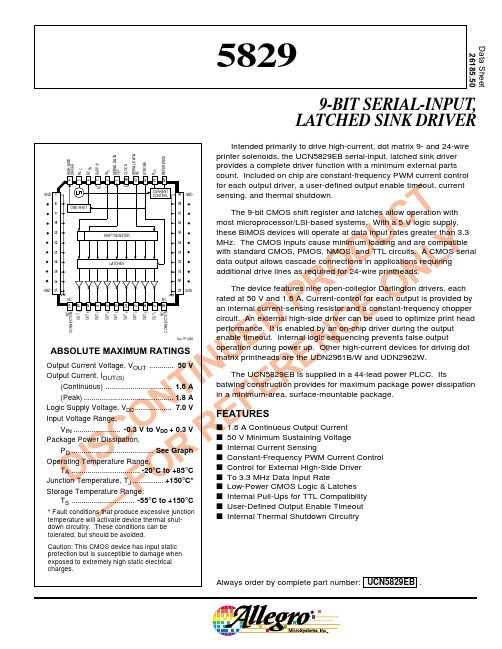
T E Logic Supply Voltage, VDD .................. 7.0 V N F Input Voltage Range, O E VIN ....................... -0.3 V to VDD + 0.3 V
12.5
= 6°C/W R θJT
10
7.5
5.0
2.5
0 25
R θJA = 30°C/W
50
75
100
TEMPERATURE IN °C
125
150
Dwg. GP-020B
115 Northeast Cutoff, Box 15036 Worcester, Massachusetts 01615-0036 (508) 853-5000 Copyright © 1991, 1995 Allegro MicroSystems, Inc.
Storage Temperature Range,
F TS ............................... -55°C to +150°C
* Fault conditions that produce excessive junction
— temperature will activate device thermal shut-
FEATURES
s 1.6 A Continuous Output Current s 50 V Minimum Sustaining Voltage s Internal Current Sensing s Constant-Frequency PWM Current Control s Control for External High-Side Driver s To 3.3 MHz Data Input Rate s Low-Power CMOS Logic & Latches s Internal Pull-Ups for TTL Compatibility s User-Defined Output Enable Timeout s Internal Thermal Shutdown Circuitry
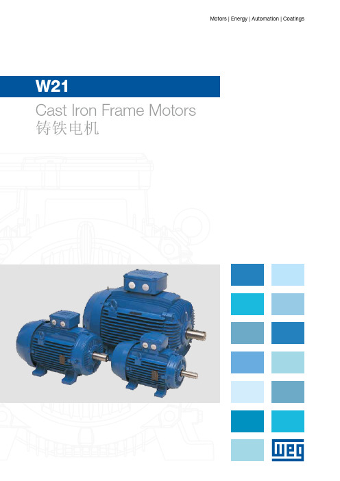
WEG电机W21样本 (2)
10
22 478 82,0 2965
7,7 2,4 3,0
1,41
21
46
749 83,0 2975
7,0 2,6 2,8
0,206
12
26 245 74,0 2960
7,0 2,8 2,8
0,251
15
33 294 74,0 2960
7,0 2,3 3,1
0,314
16
35 356 82,0 2960
7,5 2,4 3,2
0,377
13
29
410 82,0 2965
8,3 2,6 3,0
0,502
180M
71,4
30 40
200L
96,8
37 50
200L
119
45 60 225S/M
145
55 75 250S/M
177
75 100 280S/M
240
90 125 280S/M
289
110 150 315S/M
353
132 175 315S/M
424
150 200 315S/M
482
160 220 315S/M
Improved Efficiency EFF2 - RAL 5007 High Efficiency EFF1 - RAL 5009 Premium Efficiency Exceeds EFF1 - RAL 6021
g 三相多电压,IP55, TEFC g 铸铁机座(63至355 M/L) g 鼠笼转子 / 铸铝 g 两端盖装V型圈 g 冷凝排污孔 g AISI 316不锈钢铭牌 g N设计 g F级绝缘(△T=80K) g 连续滴浸工艺(225S/M-355M/L) g 连续工作制 – S1 g 环境温度:40°C , 1000米海拔. g 尺寸参照IEC72标准,性能特征 g 参照IEC34标准 g 机座225S/M及以上带加油装置 g 接线盒螺套为米制螺纹 g 160M及以上机座每相带1个热敏电阻 g 热敏电阻 g 适合变频器应用 g 油漆颜色:
575-8;575-4;6092;6091;476-2;中文规格书,Datasheet资料
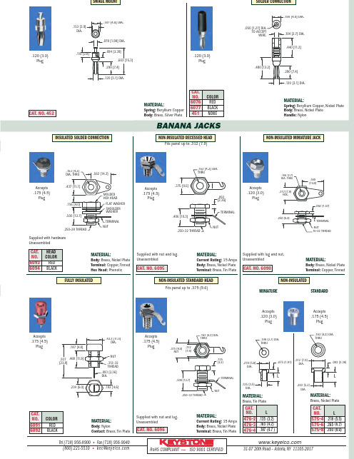
1BANANA JACKSTel (718)956-8900•Fax (718)956-9040(800)221-5510•kec@31-0720th Road –Astoria,NY 11105-2017RoHS COMPLIANT ~ISO 9001CERTIFIED®MATERIAL:Spring:Beryllium Copper Body:Brass,Silver PlateCAT.NO.452MATERIAL:Spring:Beryllium Copper,Nickel Plate Body:Brass,Nickel Plate Handle:Nylon.120(3.0)Plug.120(3.0)Plug.603 [15.3].153 [3.9]DIA..187 [4.8]DIA..110 [2.8].094 [2.39].078 [1.98]DIA..120 [3.1]DIA..290 [7.4].050 [1.27] DIA.TO ACCEPTWIRE..190 [4.9]DIA..104 [2.7] DIA..440 [11.2].480 [12.2].120 [3.1] DIA..290 [7.4]CAT.NO.COLOR 6076RED 6077BLACK 451NONESOLDER CONNECTIONSWAGE MOUNT MATERIAL:Body:Brass,Nickel Plate Terminal:Copper,TinnedAccepts .120(3.0)Plug.550[14.0].062 [1.57].312 [7.9]HEX..250 [6.4].106 [2.7]DIA.THRU10-32 THREADNUTTERMINAL MATERIAL:Body:Brass,Nickel Plate Terminal:Copper,Tinned Hex Head:PhenolicMATERIAL:Current Rating:15Amps Body:Brass,Nickel Plate Terminal:Brass,Tin PlateMATERIAL:Brass,Tin PlateMATERIAL:Body:NylonContact:Brass,Tin PlateCAT.NO.6096MATERIAL:Brass,Nickel PlateCAT.HEAD NO.COLOR 6093RED 6094BLACKCAT.NO.COLOR 6091RED 6092BLACKCAT.NO.6095STANDARDFULLY INSULATED Fits panel up to .375(9.6)CAT.NO.L 575-4.218(5.5)575-6.265(6.7)575-8.350(8.9)CAT.NO.L 476-2.125(3.2)476-3.165(4.2)476-4.187(4.7)Accepts .120(3.0)PlugAccepts .175(4.5)PlugFits panel up to .312(7.9)Accepts .175(4.5)PlugMATERIAL:Current Rating:15Amps Body:Brass,Nickel Plate Terminal:Brass,Tin PlateAccepts .175(4.5)PlugAccepts .175(4.5)PlugNON-INSULATED MINIATURE JACKMINIATUREINSULATED SOLDER CONNECTIONCAT.NO.6090.562[14.3].500[12.7].437[11.1].156[4.0].163[4.2]DIA.THRU.250-28 THREADNUTTERMINAL MOLDED HEX HEADFLAT WASHER SHOULDER WASHER.375 [9.5].406 [10.3].093 [2.36].163 [4.2] DIA.THRU.250-32 THREADTERMINALNUT.312[7.9].500 [12.7].375 [9.5]NUT.125 [3.2]TERMINALNUT.250-32 THREAD.163 [4.2] DIA.THRU.135 [3.5]DIA.L.075[1.91].218[5.6]DIA..106 [2.7]DIA.THRU.203 [5.2]DIA..093 [2.36].312 [7.9]DIA..163 [4.2] DIA.THRUL.182[4.6].937[23.8].433[11.0]DIA..187[4.8].234[6.0].468[11.9].093[2.36]DIA..312-32THREAD NUT Supplied with hardware UnassembledSupplied with nut and lug.UnassembledSupplied with lug and nut.UnassembledSupplied with nut and lug.UnassembledNON-INSULATEDAccepts .175(4.5)PlugNON-INSULATED STANDARD HEADNON-INSULATED RECESSED HEAD分销商库存信息:KEYSTONE-ELECTRONICS575-8575-46092 6091476-2476-4 575-660766077 60946093。
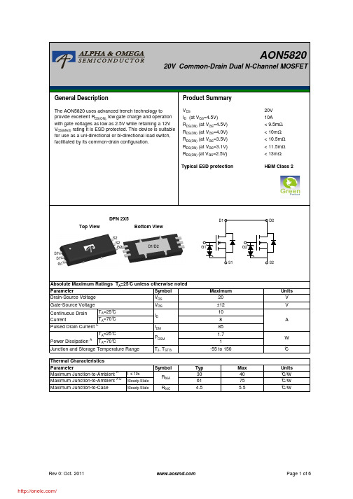
AON5820;中文规格书,Datasheet资料
Crss
Reverse Transfer Capacitance
Rg
Gate resistance
VGS=0V, VDS=10V, f=1MHz VGS=0V, VDS=0V, f=1MHz
1000 1255 1510 pF
150 220 290 pF
100 168 235 pF
2.5
KΩ
SWITCHING PARAMETERS
Qrr
Body Diode Reverse Recovery Charge IF=10A, dI/dt=500A/µs
12
15
18
nC
A. The value of RθJA is measured with the device mounted on 1in2 FR-4 board with 2oz. Copper, in a still air environment with TA =25°C. The Power dissipation PDSM is based on R θJA and the maximum allowed junction temperature of 150°C. The value in any given application depends on the user's specific board design.
VDS=VGS, ID=250µA
0.3 0.65 1.0
V
ID(ON)
On state drain current
VGS=4.5V, VDS=5V
85
A
VGS=4.5V, ID=10A
5.5 7.4 9.5 mΩ
TJ=125°C 8
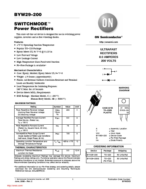
BYW29-200G;中文规格书,Datasheet资料
0.5 1.0 2.0
5.0 10
20
t, TIME (ms)
Figure 6. Thermal Response
50 100 200
ULTRAFAST RECTIFIERS 8.0 AMPERES 200 VOLTS
1 4
3
MARKING
4
DIAGRAM
1 3
CASE 221B TO−220B PLASTIC
AY WWG BYW29-200
KA
A Y WW BYW80−200 G KA
= Assembly Location = Year = Work Week = Device Code = Pb−Free Package = Diode Polarity
2
IF(AV), AVERAGE FORWARD CURRENT (AMPS)
r(t), TRANSIENT THERMAL RESISTANCE (NORMALIZED)
BYW29−200
PF(AV), AVERAGE POWER DISSIPATION (WATTS)
*For additional information on our Pb−Free strategy and soldering details, please download the ON Semiconductor Soldering and Mounting Techniques Reference Manual, SOLDERRM/D.
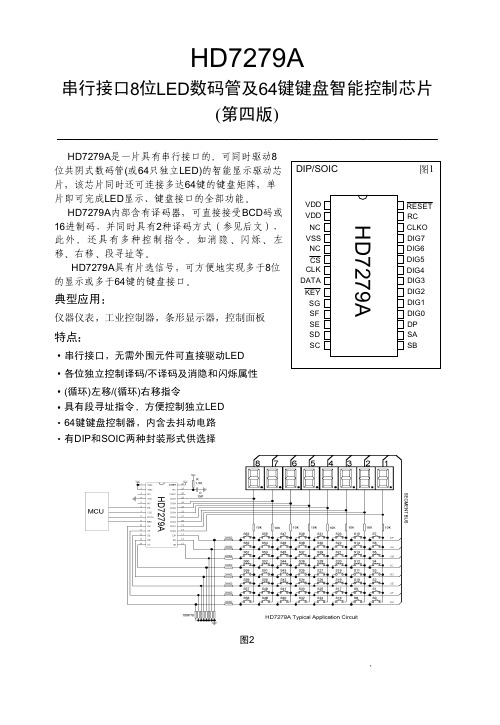
HA7279ADataSheet
Vno
½¾«DE
K½¾ª«DE\» A(BCD%&
±«6ÂÃÄ
<ÅLÆ-ÂÇÈÉ
&
ÜÝÛ
Y
Ì
1
1
"
<ÅLÆ-ÂÇÈÉ
2 ®[ ^®º 2 5 2 L P 3 9
¤V «6T ´uV
µ¶
Vno
5 2 L
wx¹ª«DET P 3 9
Vno
«DE V ½¾ª«DE"
Zâ²0 ¦ ÉãY³¦ g¦%
É㳦Yäåá<
no
o
"n
ËE³£ÉãYnoqr çèT éêYWXV³ë"no
! % -./012
78 "
' # # z() 78V,+1 N.OL 1() yzCLN.OL1 dyz#eDE1 78¢ N 78V DE 78+~> L` ¡xL()(9 ! () dN.OL1 yzCDE
2N2905A;中文规格书,Datasheet资料
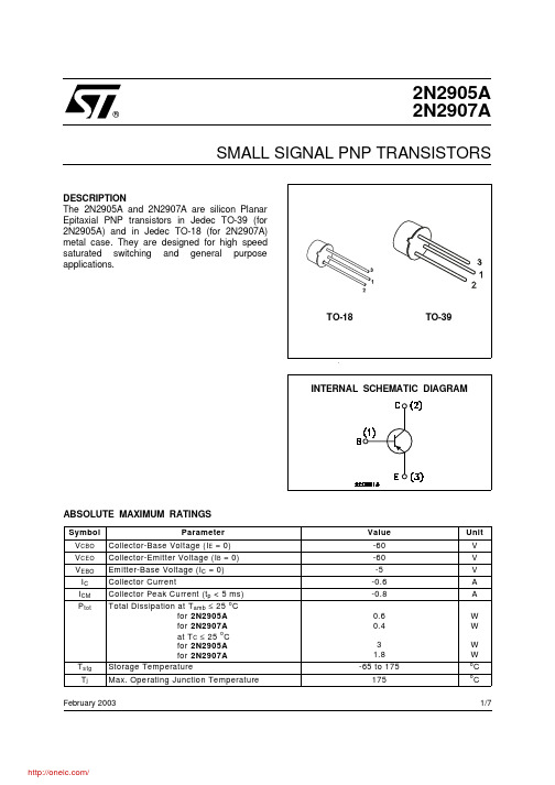
2N2905A 2N2907ASMALL SIGNAL PNP TRANSISTORSDESCRIPTION The 2N2905A and 2N2907A are silicon Planar Epitaxial PNP transistors in Jedec TO-39 (for 2N2905A) and in Jedec TO-18 (for 2N2907A)metal case. They are designed for high speed saturated switching and general purpose applications.February 2003ABSOLUTE MAXIMUM RATINGS®1/7THERMAL DATAELECTRICAL CHARACTERISTICS (T case = 25 oC unless otherwise specified)** See test circuit2N2905A/2N2907ANormalized DC Current Gain.Collector Emitter Saturation Voltage.Collector Base and Emitter-base capacitances.Switching Characteristics.2N2905A/2N2907A2N2905A/2N2907A.Test Circuit for t on, t r, t d ArrayTest Circuit for t off, t o, t f.2N2905A/2N2907A2N2905A/2N2907AInformation furnished is believed to be accurate and reliable. However, STMicroelectronics assumes no responsibility for the consequences of use of such information nor for any infringement of patents or other rights of third parties which may result from its use. No license is granted by implication or otherwise under any patent or patent rights of STMicroelectronics. Specification mentioned in this publication are subject to change without notice. This publication supersedes and replaces all information previously supplied. STMicroelectronics products are not authorized for use as critical components in life support devices or systems without express written approval of STMicroelectronics.The ST logo is a trademark of STMicroelectronics © 2003 STMicroelectronics – Printed in Italy – All Rights ReservedSTMicroelectronics GROUP OF COMPANIESAustralia - Brazil - Canada - China - Finland - France - Germany - Hong Kong - India - Israel - Italy - Japan - Malaysia - Malta - Morocco - Singapore - Spain - Sweden - Switzerland - United Kingdom - United States.2N2905A/2N2907A分销商库存信息: STM2N2905A。
1-829094-6资料
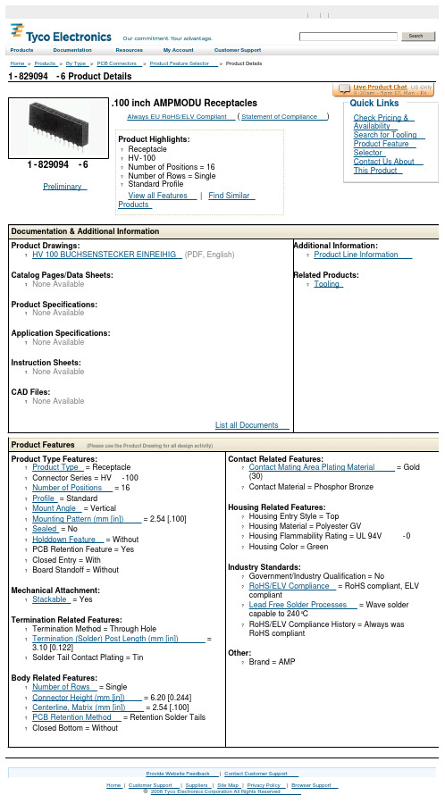
1-829094-6 Product DetailsHome | Customer Support | Suppliers | Site Map | Privacy Policy | Browser Support© 2008 Tyco Electronics Corporation All Rights Reserved SearchProducts Documentation Resources My Account Customer Support Home > Products > By Type > PCB Connectors > Product Feature Selector > Product Details1-829094-6Preliminary .100 inch AMPMODU ReceptaclesAlways EU RoHS/ELV Compliant (Statement of Compliance)Product Highlights:?Receptacle?HV-100?Number of Positions = 16?Number of Rows = Single?Standard ProfileView all Features | Find SimilarProductsCheck Pricing &AvailabilitySearch for ToolingProduct FeatureSelectorContact Us AboutThis ProductQuick LinksDocumentation & Additional InformationProduct Drawings:?HV 100 BUCHSENSTECKER EINREIHIG(PDF, English)Catalog Pages/Data Sheets:?None AvailableProduct Specifications:?None AvailableApplication Specifications:?None AvailableInstruction Sheets:?None AvailableCAD Files:?None AvailableList all Documents Additional Information:?Product Line InformationRelated Products:?ToolingProduct Features (Please use the Product Drawing for all design activity)Product Type Features:?Product Type = Receptacle?Connector Series = HV-100?Number of Positions = 16?Profile = Standard?Mount Angle = Vertical?Mounting Pattern (mm [in]) = 2.54 [.100]?Sealed = No?Holddown Feature = Without?PCB Retention Feature = Yes?Closed Entry = With?Board Standoff = WithoutMechanical Attachment:?Stackable = YesTermination Related Features:?Termination Method = Through Hole?Termination (Solder) Post Length (mm [in]) =3.10 [0.122]?Solder Tail Contact Plating = TinBody Related Features:?Number of Rows = Single?Connector Height (mm [in]) = 6.20 [0.244]?Centerline, Matrix (mm [in]) = 2.54 [.100]?PCB Retention Method = Retention Solder Tails ?Closed Bottom = Without Contact Related Features:?Contact Mating Area Plating Material = Gold(30)?Contact Material = Phosphor BronzeHousing Related Features:?Housing Entry Style = Top?Housing Material = Polyester GV?Housing Flammability Rating = UL 94V-0?Housing Color = GreenIndustry Standards:?Government/Industry Qualification = No?RoHS/ELV Compliance = RoHS compliant, ELVcompliant?Lead Free Solder Processes = Wave soldercapable to 240°C?RoHS/ELV Compliance History = Always wasRoHS compliantOther:?Brand = AMPProvide Website Feedback | Contact Customer Support。
Datasheet_Flatpack2_48_2000_HE ELTEK通信电源规格书

85-300 VAC (Nominal 176 – 275 VAC)
45 to 66Hz
11.6 Arms maximum at nominal input and full load
> 0.99 at 50% load or more
o Varistors for transient protection o Mains fuse in both lines o Disconnect above 300 VAC
Broadband and network access Increasing network speed demands flexible and expandable DC power solutions. The Flatpack2 HE rectifiers are your key building blocks for future needs.
IEC 60950-1 UL 60950-1 CSA 22.2
EMC
ETSI EN 300 386 V.1.3.2 EN 61000-6-1 (immunity, light
industry) EN 61000-6-2 (immunity, industry) EN 61000-6-3 (emission, light industry) EN 61000-6-4 (emission, industry) Telcordia NEBS GR1089 CORE
Hale Waihona Puke Alarms:o Low mains shutdown o High temperature shutdown o Rectifier Failure o Overvoltage shutdown on output o Fan failure o Low voltage alarm at 43.5V o CAN bus failure
中文-AL锂电规格书60V 4A

Revision No.: A01充电器中文规格书Specification of Battery Charger型号:KP6004AL69.4V/ 4A 锂电池充电器(全铝外壳)69.4V / 4A LITHIUM BATTERY CHARGERSubject to change without prior notice, please feel free to contact us for latest information.1.概述Battery Charger6004AL170×90×63mm can work normally under69.4V dc/4A and with reverse polarity protection.此型号6004AL 170×90×63mm的铝质外壳充电器能在输出69.4V dc/4A下工作,具有反接保护功能。
2.主要参数最大输出功率输入电压最大输出电压最大输出电流误差范围360W 220Vac +69.4+/-0.1Vdc 4A +/-0.1V3.环境条件No. 项目技术参数备注1 湿度5~95% 带包装2 海拔≤3000m正常工作4.技术特征4.1 输入特征:No. 项目技术参数备注1 额定输入电压220Vac110/230Vac2 电压输入范围180 ~ 264Vac3 电压输入频率50~60 Hz4.2 输出特征和充电模式:No. 项目技术参数备注1 CC (恒流充电) ≤69.4Vdc, 4A2 CV (恒压充电) 69.4Vdc,4A↓恒压=电池最大充电电压3 关断69.4V 0.2A→04 效率≥90% Vin=110Vac, rated load4.3 保护特征:No. 项目技术参数备注1 过压保护是2 限压保护充电器设置最大输出电压,不会超过电池的最大充电电压3 过热保护N/A4 限流保护是At CC mode5 短路保护短路保护后充电器会自动恢复6 反接保护当输出线接反后充电器不会工作,直到使用者接正确后方可启动4.4 充电指示灯No. 项目状态备注1 电源LED1: 红灯2 充电LED2: 红灯3 充满LED2: 绿灯4 输出电压数显否5 输出电流数显否5.安全&EMCNo. 项目标准( 或测试条件) 备注1 电气强度测试输入-输出1500V ac/10mA/1min 无故障2 绝缘电阻输入-接地≥10Mohm@500Vdc 输出-接地≥10Mohm@500Vdc3 泄露电流<3.5mA Vin=264Vac4 安全标准CE / UL compliant5 电池兼容性EN55022:1998+A1:2000+A2:2003EN55024:1998+A1:2001+A2:2003 (EN61000-4-2:1995+A1:1998+A2:2001) EN61000-4-3:2002EN6100-4-4:1995+A1:2000+A2:2001 EN61000-4-5:1995+A1:2000EN61000-4-6:2001EN61000-4-11:2001)6 低电压测试EN60335-1:2002+EN60335-2-29:2002Remark: Discrimination A- Function OK under technical requirement range;Discrimination B- Function temporarily debasement without reposition and halt is allowed;Discrimination R- Physical damage or failure of equipment are not allowed, but damage of protection device(fuse) caused by interference signal of outside is allowed, and the whole equipment canwork normally after replacement of protection device and reset of running parameter6.环境测试要求No. 项目技术参数备注1 最高环境工作温度+40℃Features ok2 最底环境工作温度-10℃Features ok3 最高存储温度+70℃Work normally after recovery under normal temperature for 2hours4 最低存储温度-40℃Work normally after recovery under normal temperature for 2hours5 随即振动20Hz to 2000Hz 3Grms 20hours per axis6 重复震动40g peak 3 orthogonal axes, 3+ and 3- in each axis, 11ms pulse width7 热度测试-35℃to 75℃, <3min transition, 2.5hours dwell, 200cycle8 跌落测试BS EN60068-2-32:1993 TEST ED: freefall appendix B 7.机械特征外壳材质:铝外壳尺寸: L*W*H=170×90×63mm输入接口: meets IEC standard电源线: 1.5m length输出线: 1.5m length净重: 1.2Kg11. 充电曲线。
A2982SLWTR-T;A2982ELW;A2982ELWTR;A2982SLW;A2982SLW-T;中文规格书,Datasheet资料
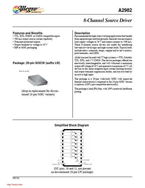
DescriptionRecommended for high-side switching applications that benefit from separate logic and load grounds, these devices encompass load supply voltages to 50 V and output currents to -500 mA. These 8-channel source drivers are useful for interfacing between low-level logic and high-current loads. Typical loads include relays, solenoids, lamps, stepper and/or servo motors, print hammers, and LEDs.All devices may be used with 5 V logic systems — T TL, Schottky TTL, DTL, and 5 V CMOS. The device packages offered are electrically interchangeable, and will withstand a maximum output off voltage of 50 V , and operate to a minimum of 5 V . A ll devices in this series integrate input current limiting resistors and output transient suppression diodes, and are activated by an active high input.The package is a 20-pin wide-body SOIC with improved thermal characteristics compared to the 18-pin SOIC version it replaces (100% pin-compatible electrically).The package is lead (Pb) free, with 100% matte-tin leadframe plating.Features and Benefits▪ TTL, DTL, PMOS, or CMOS compatible inputs ▪ 500 mA output source current capability ▪ Transient-protected outputs▪ Output breakdown voltage to 50 V ▪ DIP or SOIC packaging8-Channel Source DriverPackage: 20-pin SOICW (suffix LW)Simplified Block DiagramNot to scaleA2982(drop-in replacement for discon-tinued 18-pin SOIC variants)(NC pins, 10 and 11, not present on discontinued 18-pin LW package)Selection GuidePart NumberPackagePackingAmbient TemperatureT A (°C)A2982SLWTR-T20-pin SOICW1000 per reel–20 to 85Absolute Maximum RatingsCharacteristicSymbolNotes RatingUnitsOutput Voltage Range V CE 5 to 50V Input Voltage V IN 20V Output CurrentI OUT –500mA Package Power Dissipation P D See graph ––Operating Ambient Temperature T A Range S–20 to 85ºC Maximum Junction Temperature T J (max)150ºC Storage TemperatureT stg–55 to 150ºC2.50.5A L L O W AB L E P AC K A G E P O W E RD I S S I P A T I O N (W )AMB IE NT TE MP E R ATUR E C2.01.51.0One of Eight DriversIN 1IN 2IN 3IN 4IN 5IN 6IN 7IN 8V NCS Typical electrosensitive printer applicationPins 10 and 11 can fl oat; other pins match discontinued 18-pin SOIC: 1 to 9 same, pins 12 to 20 match pins 10 to 18ELECTRICAL CHARACTERISTICS 1,2 at T A = +25°C (unless otherwise speci fi ed).1Negative current is de fi ned as coming out of (sourcing) the speci fi ed device terminal.2All unused inputs must be connected to ground. Pull-down resistors (approximately 10 k Ω) are recommended for inputs that are al-lowed to fl oat while power is being applied to V S .3All inputs simultaneously.4Turn-off delay is in fl uenced by load conditions. Systems applications well below the speci fi ed output loading may require timing con-siderations for some designs, i.e., multiplexed displays or when used in combination with sink drivers in a totem pole con fi guration.Characteristic Symbol Test ConditionsTest Fig.Min.Typ.Max.Units Output Leakage Current 3I CEX V IN = 0.4 V, V S = 50 V1——20μA Output Sustaining Voltage V CE(SUS)I OUT = -45 mA—35——V Collector-Emitter Saturation Voltage V CE(SAT)V IN = 2.4 V, I OUT = -100 mA 2— 1.6 1.8 V V IN = 2.4 V, I OUT = -225 mA 2— 1.7 1.9 V V IN = 2.4 V, I OUT = -350 mA2— 1.8 2.0 V Input CurrentI IN(ON)V IN = 2.4 V 3—140200μA V IN = 12 V3— 1.25 1.93mA Output Source Current (Outputs Open)l OUT V IN = 2.4 V, V CE = 2.0 V 2-350——mA Supply Current Leakage CurrentI S V IN = 2.4 V*, V S = 50 V 4——10mA Clamp Diode Current I R V R = 50 V, V IN = 0.4 V*5——50μA Clamp Diode Forward Voltage V F I F = 350 mA6— 1.5 2.0 V Turn-On Delay t ON 0.5 E IN to 0.5 E OUT , R L = 100Ω, V S = 35 V——0.3 2.0μs Turn-Off Delay 4t OFF0.5 E IN to 0.5 E OUT , R L = 100Ω, V S = 35 V, See Note——2.010μsAllowable peak collector current as a function of duty cycle100150200250300350400450500A L L O W A B L E P E A K C O L L E C T O R C U R R E N T I N m A A T 50°CPER CENT DUTY CYCLE300400A L L O W AB L E P E A KC O L L E C T O R C U R R E N T I N m A A T 70°CPER CENT DUTY CYCLEDwg. No. A-11,107BDwg. No. A-11,108BInput current as a functionof input voltageT YP I C A L2.5I N P U T C U R R E N T , I (m A )I N2.01.51.00.524681012INPUT VOLTAGE (VOLTS)MA X I M UMDwg. No. A-11,115BLW Package, 20-Pin SOICWA Terminal #1 mark areaB PCB Layout Reference ViewFor Reference OnlyDimensions in millimeters(Reference JEDEC MS-013 AC)Dimensions exclusive of mold flash, gate burrs, and dambar protrusions Exact case and lead configuration at supplier discretion within limits shown B Reference pad layout (reference IPC SOIC127P1030X265-20M)All pads a minimum of 0.20 mm from all adjacent pads; adjust as necessary to meet application process requirements and PCB layout tolerances+0.07–0.06Revision HistoryRevision Revision Date Description of RevisionRev. U April 30, 2012Update product availabilityCopyright ©1977-2012, Allegro MicroSystems, Inc.Allegro MicroSystems, Inc. reserves the right to make, from time to time, such departures from the detail specifi cations as may be required to permit improvements in the performance, reliability, or manufacturability of its products. Before placing an order, the user is cautioned to verify that the information being relied upon is current.Allegro’s products are not to be used in life support devices or systems, if a failure of an Allegro product can reasonably be expected to cause the failure of that life support device or system, or to affect the safety or effectiveness of that device or system.The information included herein is believed to be accurate and reliable. However, Allegro MicroSystems, Inc. assumes no responsibility for its use; nor for any infringement of patents or other rights of third parties which may result from its use.For the latest version of this document, visit our website:分销商库存信息:ALLEGROA2982SLWTR-T A2982ELW A2982ELWTR A2982SLW A2982SLW-T A2982SLWTR UDN2981A UDN2982A UDN2982LW UDN2982LW-T UDN2982LWTR A2982ELW-T UDN2981A-T UDN2982A-T A2982ELWTR-T UDN2982LWTR-T。
29123;中文规格书,Datasheet资料

Web Site: Forums: Sales: sales@Technical: support@Office: (916) 624-8333Fax: (916) 624-8003Sales: (888) 512-1024Tech Support: (888) 997-8267 Hitachi® HM55B Compass Module (#29123)General DescriptionThe Hitachi HM55B Compass Module is a dual-axis magnetic field sensor that can add a sense of direction to your next electronic or robotic project. The sensing device on the Compass Module is a Hitachi HM55B chip. An onboard regulator and resistor protection make the 3 volt HM55B chip compatible with 5 volt BASIC Stamp® microcontroller supply and signal levels. The Compass Module also makes all the power and signal connections on the tiny surface mount HM55B chip accessible in a breadboard-friendly 0.3 inch wide 6-pin DIP package. Acquiring measurements from the module is made easy with the BASIC Stamp 2 microcontroller's SHIFTIN and SHIFTOUT commands, which are designed for synchronous serial communication with chips like the HM55B.Features•Sensitive to microtesla (µT) variations in magnetic field strength•Simplifies direction by resolving magnetic field measurements into two component axes•Good for 6-bit (64-direction) resolution measurements after software calibration•Only 30 to 40 ms between start measurement and data-ready•Built-in resistor protection for data pins eliminates bus conflict risks•Compact and breadboard-friendly 0.3 inch, 6-pin DIP package•Compatible with all BASIC Stamp, Javelin Stamp and SX microcontrollers•Makes communication and direction calculations especially easy with the PBASIC commands SHIFTOUT, SHIFTIN, and ATN for the BASIC Stamp 2 series of microcontrollersApplication Ideas•Mobile robot direction sensor•Handheld electronic compass•Weathervane indicator for remote weather stations•Audible compass for the vision impaired•Automotive electronic compassQuick Start Circuit29123Downloading the Example ProgramsThe example programs featured in the Source Code section (pages 12 - 24) are also available for download from the Hitachi HM55B Compass Module product page at .√Go to /detail.asp?product_id=29123.√Click the "Hitachi HM55B Compass Module Source Code (.zip)" link and download the file.√Unzip to a convenient folder.Connecting and Testing the Compass ModuleThis section contains connection and test instructions for the Parallax BASIC Stamp 2® series and Ubicom SX microcontrollers.BASIC Stamp 2 SeriesUse the instructions in this section to test your Hitachi HM55B Compass Module if you have a BASIC Stamp 2, 2sx, 2e, 2p, 2pe, or 2px. The goal of this first test is to verify that the module is connected, functional, and communicating properly with the BASIC Stamp. Since this first test is run before calibration, there may sizeable differences between magnetic compass directions and what the module reports.√Build the circuit shown on page 1.√Place your board on a level surface away from magnetic field disturbances. Common culprits include magnetic compasses, motors, bar/horseshoe/ring magnets, and large metal objects.Also, make sure your programming cable and power cords do not wrap around or pass near the sensor.√Open TestHm55bCompass.bs2 with the BASIC Stamp Editor (v2.0 or later). Update the $STAMP directive if needed, then run the program.√Test your Compass Module for direction detection as shown below, comparing your degree measurements to the compass legend in the figure.CalibrationThe calibration and test-calibration programs will compensate for the effects of magnetic fields that may be resident to the module PCB and the carrier board it's mounted on, as well as nearby jumper wires and batteries. It also corrects for the HM55B chip's axis sensitivity, offset and skew errors, if any. You will need a magnetic compass to verify magnetic north as a reference. After calibration, the Hitachi HM55B Compass Module should be able to accurately discern 64 or more angles, referenced to magnetic north.√Make a printout of the 16-segment compass shown below.√Align the printout to magnetic north with the aid of the magnetic compass.√Affix the aligned printout to your work surface.√Make sure to set the magnetic compass well away from the printout before continuing.√Align the Compass Module to magnetic north by lining up the edge of your carrier board with the dashed line that passes through the 0° mark.The program CalibrateHm55bCompass.bs2 will prompt you to take a first series of measurements at 90°increments to gather compass offsets. Then, you will take a second series of measurements at 22.5° increments to gather information for a linear interpolation table. Both sets of measurements will be saved in the BASIC Stamp EEPROM so that the TestCalibratedHM55BCompass.bs2 program can use them.√Run CalibrateHm55bCompass.bs2.√Make sure to click the Transmit windowpane shown in this figure before following and responding to the Debug Terminal prompts.√When you have completed the calibration process, run TestCalibratedHM55BCompass.bs2. Array ArrayCalibrateHM55BCompass.bs2 writes the calibration values to EEPROM, so they will be available for TestCalibratedHM55BCompass.bs2 even after the power is reset. TestCalibratedHM55BCompass.bs2 will display the angle from north in both binary radians (brads) and degrees. When you run this program after calibration, the accuracy of the degree measurements should be significantly improved. While degrees parse a full circle into 360 equal segments, brads parse the circle into 256 segments. North is still 0, but the brad measurements for east, south and west are 64, 128, and 192 respectively. In applications where accuracy is the top priority, use the brad measurements because they introduce one less rounding error into the measurement. Further accuracy improvements can be realized if both the calibration and calibration-test programs are modified to average multiple measurements.Testing SensitivityThe Compass Module operates by comparing the magnetic field intensities sensed by its two perpendicular axes. The magnetic field strength corresponding to a measurement of 1 should resolve to somewhere between 1 and 1.6 µT. To find out how many microteslas per unit each axis reports with your particular Compass Module, use TestCalibratedHM55BCompass.bs2. Start by finding the maximum possible axis measurement. Do this by orienting the x-axis to magnetic north, then tilt up and down until you find the highest value. Compare this to the total magnetic field intensity in your area. In thecontinental US, you can find a Total Intensity Map on this page:/articles/geology/a_geomag.html.Make sure to divide their nanotesla (nT) values by 1000 to convert to microteslas (µT).SX MicrocontrollerWhile this connection and testing procedure is set up for the SX-28, it should work on any of the SX series of microcontrollers with a simple update of the device directive. Make sure you are using the SX-Key v3.1 IDE v3.10 or newer, along with the SX-Key and an SX-28 chip.√Build the circuit shown below.√Open TestHm55bCompass.SXB with the SX-Key IDE.√Save, Compile, and Debug (CTRL-S, A, D)√Click the Debug window's Poll button. If the Watch window is not visible, also click the Watch button to bring it to the foreground.√Monitor the Watch window as you point the module in various directions.√Use arctan(-y/x) to calculate the heading angle, counterclockwise from north.Resources and DownloadsCheck out the Hitachi HM55B Compass Module product page for example programs, the HM55B datasheet, and more:/detail.asp?product_id=29123Theory of OperationThe Hitachi HM55B Compass Module has two axes, x and y. Each axis reports the strength of the magnetic field's component parallel to it. The x-axis reports (field strength) × cos(θ), and the y-axis reports the (field strength) × sin(θ). To resolve θ into a clockwise angle from north, use arctan(-y/x), which in PBASIC 2.5 is x ATN -y. The ATN command returns the angle in binary radians. To convert to degrees with PBASIC, just apply */ 360 to the variable storing the binary radian measurement.The Hitachi HM55B chip on the Compass Module reports its x and y axis measurements in terms of microteslas (µT) in 11-bit signed values. The HM55B is designed to return a value of 1 for a north magnetic field of 1 µT parallel to one of its axes. If the magnetic field is south, the value will be -1. Keep in mind that these are nominal values. According to the HM55B datasheet, the actual µT value for a measurement of 1 could range anywhere from 1 to 1.6 µT. Also keep in mind that a negative 11-bit value will not appear negative in a word variable unless a mask is applied. For example, when bit-10 is 1, bits 11 to 15 are also changed to 1 with a mask in the test and calibration programs.The microcontroller connected to the HM55B must control its enable and clock inputs and use synchronous serial communication to get the axis measurements from its data input and data output pins. For example, a BASIC Stamp 2 can be programmed to control the Compass Module's enable lines with HIGH/LOW and send values that reset the device and start a measurement with SHIFTOUT commands. The SHIFTOUT command controls the Compass Module’s clock input as it sends data bit values to its data input. The converse of SHIFTOUT is SHIFTIN, which also controls the device's clock input as it collects data bits sent by the device's data output pin.It takes the HM55B 30 to 40 ms to complete a given measurement. The microcontroller can either perform other tasks during this time or poll until the measurement is complete. The polling is a combination of SHIFTOUT commands that request the status, and SHIFTIN commands that acquire the status. When the SHIFTIN receives status flags indicating that the measurement is complete, a second and third SHIFTIN command can then store the 11-bit x and y axis measurements in variables.Precautions• Do not apply voltages to the device that are outside the values stated in the Pin Definitions and Ratings section.•Do not operate or store the Compass Module near sources of strong magnetic fields. Strong magnetic fields can be created by bar and ring magnets, electric motors, and other coil elements such as solenoids, relays, and large inductors.• Do not apply magnetic fields in excess of 300 µT to the Compass Module. Magnetic fields stronger than 300 µT can permanently damage the sensor.•Mount the Compass Module as far away as possible from magnetic field disturbances. These include magnets (including compass needles), motors, power cords, coils, metal boxes, and sometimes the ground.angle θ= arctan(-y/x)SpecificationsSymbol Quantity MinimumTypical MaximumUnitsB SE Sensitivity † 1.0 1.6 µT/lsbH Linear measurement range † -180 180 µT d θIndividual axis offset36°T CONV Conversion time † 30 40 ms T OPE Operating temperature 070 °C† From Hitachi HM55B DatasheetPin Definitions and RatingsSymbol QuantityMinimum Typical Maximum UnitsVcc Supply Voltage 4.8 5.0 5.2 VIcc(Ave) Average active supply current * 5 7mA Icc(Pk) Peak instantaneous current ** 30 45 mA Icc(Sb) Standby supply current 2 3 mA GND Ground reference connection 0 V V OH Signal high transmit (Dout) Vcc × 0.9 Vcc Vcc + 0.5 V V OL Signal low transmit (Dout) GND - 0.3 GND Vcc × 0.15 V V IH Signal high receive (/En, CLK, Din) Vcc × 0.8 Vcc Vcc + 0.3 V V ILSignal low receive (/En, CLK, Din)- 0.3GNDVcc × 0.12V** Typical duration is 5 µs(1) Din - Serial data input (2) Dout - Serial data output (3) GND - Ground -> 0 V(4) CLK - Synchronous clock input (5) /EN - Active-low device enable (6) Vcc -+5 V power input29123Connection DiagramsThe 3-wire interface is recommended for most applications. While all the connections shown here are to individual I/O pins, the /EN pin is the only one that needs a dedicated I/O pin. The Din/Dout pins can share a line with other synchronous serial devices, and likewise with CLK.The Din and Dout pins do not have to be tied together; they can also be controlled individually. This makes it possible to share communication lines with other synchronous serial devices that have dedicated input and output lines.Command SetThese commands are shifted-out to the Compass Module.Binary ValueQuantity0000 Reset device 0001 Start measurement 0011Report measurement status (and transmit the measurement if it's ready)4-wire interface3-wire interfaceStatus FlagsThe Compass Module will reply to the report measurement status command with one of these values.Binary Value QuantityBits - 3210 3 and 2 indicate measurement completion, 1 and 0 indicate measurement errors 1100 11 -> Measurement completed; 00 -> no errors00XX Measurement still in progress, or the device has been reset.XX11 /EN did not receive low-high-low signal between start and report commandsCommunication ProtocolAll values transmitted to and received from the Compass Module are most significant bit first, with the bit value valid after the clock signal's rising edge. For the BASIC Stamp 2, this means set the SHIFTOUT command’s Mode argument to MSBFIRST, and the SHIFTIN command’s Mode argument to MSBPOST.To reset the HM55B, take /EN from high to low, and shift-out %0000, then set /EN high again.After reset, start a measurement by taking /EN low again, then shift-out %1000. Leave /EN low until checking the measurement status.To check the measurement status, start by sending a positive pulse to /EN. Then, shift-out %1100, and shift-in the status flags. While the measurement is in progress, the end flag and error flag will both be 00. The compass Module may be polled for status repeatedly until the measurement is complete, at which point the end flag will change to 11. Upon receipt of %1100, discontinue polling. Leave /EN low, and move on to shifting-in the x and y-axis values.Shifting-in the x and y-axis values is a simple matter of shifting-in 11 bits for the x-axis measurement followed by 11 more bits for the y-axis measurement. After completing the y-axis shift-in, set the /EN pin high again.Module Dimensions分销商库存信息: PARALLAX 29123。
广百思 GBS-8219 产品说明书

- 0 -重要信息在您使用本产品之前,请详细阅读此产品使用手册,手册内包含所有产品相关的警告及重要事项。
若您能遵守本手册的安全注意事项,并在正确的方式下操作,本公司保证本产品能长久使用。
但不适用于以下情况: z 未经授权而私自进行维修或者是零件更换等操作。
z 由事故造成的损害,包含但不限于闪电、火灾、曝露于雨中或水气中。
z 使用的电源类型不在本产品的电压允许范围内,请参考包装内随附电源转接器后面粘贴的标签信息上所标示的额定电压范围。
z 产品上的型号标签被修改,或保修标签被私自拆下。
安全注意事项触电危险 切勿打开为防止触电,请勿打开产品外盖。
本产品未提供用户维修调整的零件,请返回原厂进行维修。
危险: 请小心电压z 电源插座:为避免短路触电或火灾,请确认使用的电源插座类型是在本产品的电压允许范围内,请参照电源转接器后面粘贴的标签信息。
z 电源负载:请勿超过墙壁插座、延长线或其它多孔插座上的负载量,以避免火灾或触电的情况。
z 电源线:不要将任何物品及重物压在电源线上。
避免电源线被踩到或拉紧,本产品的电源线不应放于人们常出入的地方。
z 闪电或雷电:为避免闪电(雷电)或长时间不使用本产品时,请拔除电源插头,这会减少触电及火灾的危险。
警告z 请勿让任何液体溅到产品上。
不要将充满液体的容器放置在本产品上,如天那水、机油等。
z为避免触电,请勿将产品上的通风孔堵住或粘贴住;切勿拆开产品外盖,或将大头针、铁丝、异物放进通风口缝隙内。
z请将本产品安放于空置空间,并固定好,避免震动。
z 保持通风:请勿堵住本产品周边的空气流通或是放置任何重物在上面。
堵住空气流通会伤害到产品本身。
并远离阳光直射或任何高温热源。
z 暴露于水气中:为减少触电或火灾的危险,请勿将本产品放置在雨中或潮湿处。
z 在您进行安装前请您详细阅读本说明书,请不要在未明白说明书时就开始操作,将有可能无法正常使用。
- 1 -广百思科技根据长期在工业设备视频维修改造上的经验总结,收集众多客户要求和反馈,历经多年开发和测试,在GBS 8218基础上强势推出革新性工业视频转换器- GBS 8219,它能实现工业视频信号转换全自动化操作,将给您在工业显示器维修和替换方面带来实惠和便捷。
WEG电机W21样本 (2)

Standard features - 标准特征
g Three-phase multivoltage, IP55, TEFC g Cast iron frames (63 up to 355M/L) g Squirrel cage rotor / Aluminium die cast g V’Ring on both endshields g Anti-condensation drain holes g Stainless steel nameplate AISI 316 g Design N g Class “F” insulation (∆T=80 K) g Resin continuous flow for frames 225S/M up to 355M/L g Continuous duty - S1 g Ambient temperature: 40°C , 1000 m.a.s.l. g Dimensions according to IEC 72 g Performance characteristics according to IEC 34 g Regreasing nipples for frame 225S/M and above. g Metric thread cable entries in terminal box. g Thermistors (1 per phase) fitted in frame 160M and above g Suitable for Inverter Duty applications g Paint color:
7,0 2,6 2,8
0,206
12
26 245 74,0 2960
7,0 2,8 2,8
datasheet_EEH210
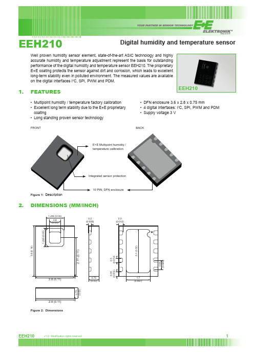
EEH210E+E Multipoint humidity /Figure 1: DescriptionDimensions (mm/inch)2.8 (0.11)3.6 (0.14)1.285 (0.05)1.285 (0.05)2.77 (0.11)0.8 (0.03)3.1 (0.12)1.7(0.067)0.65 (0.026)Figure 6: T iming Diagram for Digital Input / Output Pads, abbreviations are explained in Table 5. SDA directions are seen from the sensor.Bold SDA line is controlled by the sensor, plain SDA line is controlled by the micro-controller. Note that SDA valid read time is triggered by falling edge of anterior toggle.Pin conFigurationFigure 8: Pin Assignment (Through View): DFN-10 3.6 x 2.8Figure 11: H old master communication sequence – grey blocks are controlled by EEH210. Bit 45 may be changed to NACK followed by Stop condition (P) to omit checksum transmission.In no hold master mode, the MCU has to poll for the termination of the internal processing of the sensor. This is done by sending a Start condition followed by the I2C header (10000001) as shown in Figure 10.If the internal processing is finished, the sensor acknowledges the poll of the MCU and data can be read by the MCU. If the measurement processing is not finished the sensor answers no ACK bit and the Start condition must be issued once more.For both modes, since the maximum resolution of a measurement is 14 bit, the two last least significant bits (LSBs, bits 43 and 44) are used for transmitting status information. Bit 1 of the two LSBs indicates the measurement type (‘0’:tem-perature, ‘1’:humidity). Bit 0 is currently not assigned.Figure 12: N o Hold master communication sequence – grey blocks are controlled by EEH210. If measurement is not completed upon “read” command, sensor does not provide ACK on bit 27 (more of these iterations are possible). If bit 45 is changed to NACK followed by Stop condition (P) checksum transmission is omitted.rEsoLution rH (tyP)14 bit13 bit12 Bit1811 bit1010 bit108 bit4table 11: Measurement times for RH and T measurements at different resolutionsPlease note: I2C communication allows for repeated Start conditions (S) without closing prior sequence with Stop condition (P) – compare Figures 9, 10 and 12. Still, any sequence with adjacent Start condition may alternatively be closed with a Stop condition.soFt resetThis command (see Table 8) is used for rebooting the sensor system without switching the power off and on again. Upon reception of this command, the sensor system reinitializes and starts operation according to the default settings – with the exception of the heater bit in the user register (see Sect. 6.3). The soft reset takes less than 15 ms.Figure 13: Soft Reset – grey blocks are controlled by EEH210.user registerThe content of User Register is described in Table 10. Please note that reserved bits must not be changed and default values of respective reserved bits may change over time without prior notice. Therefore, for any writing to the User Register, default values of reserved bits must be read first. Thereafter, the full User Register string is composed ofFigure 14: R ead and write register sequence – grey blocks are controlled by EEH210. In this example, the resolution is set to 8 bit / 12 bit.crc checksumThe EEH210 provides a CRC-8 checksum for error detection.The polynomial used is x8 + x5 + x4 +1.conversion oF signal outPutDefault resolution is set to 12 bit relative humidity and 14 bit temperature reading.Measured data are transferred in two byte packages, i.e. in frames of 8 bit length where the most significant bit (MSB) is transferred first (left aligned).Each byte is followed by an acknowledge bit. The two status bits, the last bits of LSB, must be set to ‘0’ before calculating physical values.In the example of Figure 9 and Figure 10, the transferred 16 bit relative humidity data is ‘01100011010100relative Humidity ConversionWith the relative humidity data output D RH the relative humidity RH is obtained by the following formula (result in % RH), no matter which resolution is chosen:Figure 15: M ultiple byte SPI write protocol (2-byte example)Figure 16: S PI read protocol in 3-wires moderegister maPPingnamE tyPE rEgistEr aDDrEss (HEx) DEVICE ID R0FADC_RESOL R/W10Figure 17: P WM signal. Base frequency runs constantly at approximately 120 Hz. hence tas a ratio of t F.The measured data – either humidity or temperature – is provided as ratio of t PWof t F to make it independent of variations of the base frequency.Conversion of signal outputThe sensor reading is linear and hence it can be converted to a physical value by an easy linear equation.With the relative humidity signal output the relative humidity RH is obtained by the following formula (result in %RH): tFigure 18: Schematic principle of PDM signal. X represents either RH or T at different levels of sensor output.Converting PDm to analogue signalA PDM signal normally is converted to an analogue voltage signal by the addition of a low-pass filter. Figure 19 displays a typical circuit where a simple RC-filter is used.Figure 19: T ypical circuit with low pass filter (surrounded by hatched line) for analog output. Recommended component size: RLP = 100kΩ and CLP = 220nF. By pulling SCL low or high, the output value is switched to temperature or humidity, respectively.For an acceptable small ripple of the analog voltage signal, a cut-off frequency of 7 Hz is recommended. Typical values for the low pass filter components are R = 100 kΩ and C = 220 nF. The corresponding ripple of the signal is limited to maximal amplitude of ±0.2 % RH and ±0.28 °C, respectively. If larger deviations are acceptable the capacitor size can be reduced.Important: The maximum current from SDA should not exceed 40 μA. Therefore, there are restrictions on the size of the resistance RLP. Furthermore, the current should be kept as low as possible and therefore the input impedance of the reading buffer shall be larger than 50 MΩ (60 nA input biased current). Eventually, cable length between sensor and low pass filter shall be kept as short as possible in order to prevent self-heating.。
EVAL-AD7718EBZ;中文规格书,Datasheet资料
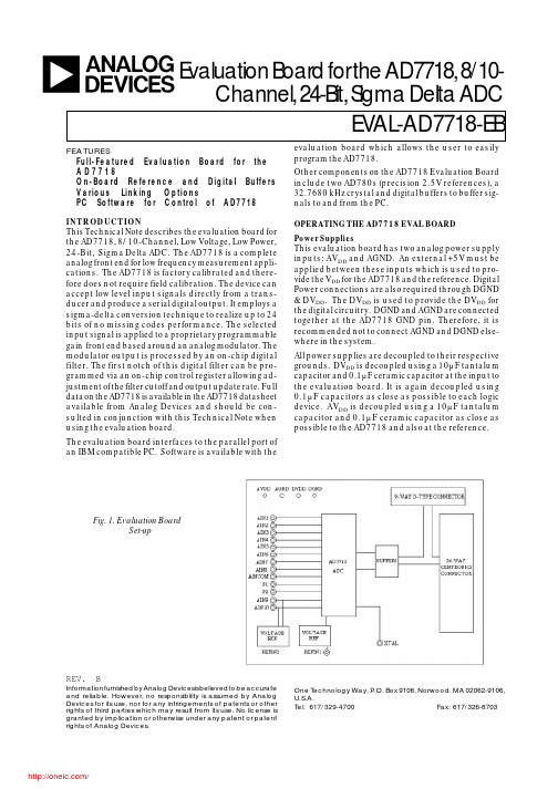
EV AL-AD7718-EBa FEATURESFull-Featured Evaluation Board for theA D 7718On-Board Reference and Digital BuffersVarious Linking OptionsPC Software for Control of AD7718REV. BInformation furnished by Analog Devices is believed to be accurateand reliable. However, no responsibility is assumed by AnalogDevices for its use, nor for any infringements of patents or otherrights of third parties which may result from its use. No license isgranted by implication or otherwise under any patent or patentrights of Analog Devices.One Technology Way, P.O. Box 9106, Norwood. MA 02062-9106,U.S.A.Tel: 617/329-4700 Fax: 617/326-8703evaluation board which allows the user to easily program the AD7718.Other components on the AD7718 Evaluation Board include two AD780s (precision 2.5V references), a 32.7680 kHz crystal and digital buffers to buffer sig-nals to and from the PC.OPERATING THE AD7718 EVAL BOARDPower Supplies This evaluation board has two analog power supply inputs: AV DD and AGND. An external +5V must be applied between these inputs which is used to pro-vide the V DD for the AD7718 and the reference. Digital Power connections are also required through DGND & DV DD . The DV DD is used to provide the DV DD for the digital circuitry. DGND and AGND are connected together at the AD7718 GND pin. Therefore, it is recommended not to connect AGND and DGND else-where in the system.All power supplies are decoupled to their respective grounds. DV DD is decoupled using a 10µF tantalum capacitor and 0.1µF ceramic capacitor at the input to the evaluation board. It is again decoupled using 0.1µF capacitors as close as possible to each logic device. AV DD is decoupled using a 10µF tantalumcapacitor and 0.1µF ceramic capacitor as close as possible to the AD7718 and also at the reference.Evaluation Board for the AD7718, 8/10-Channel, 24-Bit, Sigma Delta ADCINTRODUCTION This Technical Note describes the evaluation board forthe AD7718, 8/10-Channel, Low Voltage, Low Power,24-Bit, Sigma Delta ADC. The AD7718 is a completeanalog front end for low frequency measurement appli-cations. The AD7718 is factory calibrated and there-fore does not require field calibration. The device canaccept low level input signals directly from a trans-ducer and produce a serial digital output. It employs asigma-delta conversion technique to realize up to 24bits of no missing codes performance. The selectedinput signal is applied to a proprietary programmablegain front end based around an analog modulator. Themodulator output is processed by an on-chip digitalfilter. The first notch of this digital filter can be pro-grammed via an on-chip control register allowing ad-justment of the filter cutoff and output update rate. Fulldata on the AD7718 is available in the AD7718 datasheetavailable from Analog Devices and should be con-sulted in conjunction with this Technical Note whenusing the evaluation board.The evaluation board interfaces to the parallel port ofan IBM compatible PC. Software is available with the Fig. 1. Evaluation BoardSet-up/EV AL-AD7718-EBLINK AND SWITCH OPTIONSThere are fifteen link options which must be set for the required operating setup before using the evaluation board.The functions of these link options are outlined below.Link No.FunctionLK1-LK8 These links are in series with the AIN1 through AIN8 analog inputs respectively.With these links in place, the analog inputs on the relevant SKT input is connected directly to therespective AIN input on the part. For example, with LK1 in place, the analog input applied to SKT1is connected directly to AIN1 of the AD7718.LK9This link is in series with the AINCOM analog input.With this link in place, the analog input on SKT9 is connected directly to the AINCOM input onthe part.LK10This link is used to select the reference source for the REFIN2(+)/AIN9 input of the AD7718.With this link in position "A", REFIN2(+)/AIN9 is connected to the output of the on-board reference(AD780 - U2).With this link in position "B", REFIN2(+)/AIN9 is connected to SKT10. An external voltage appliedto SKT10 can now be used as the REFIN2(+) for the AD7718 or as analog input AIN9, dependingon how the AD7718 is configured.LK11This link is used to select the reference source for the REFIN2(-)/AIN10 input of the AD7718.With this link in position "A", REFIN2(-)/AIN10 is connected directly to AGND.With this link in position "B", the REFIN2(-)/AIN10 is connected to SKT11. An external voltageapplied to SKT11 can now be used as the REFIN2(-) for the AD7718 or as analog input AIN10,depending on how the AD7718 has been configured.LK12This link is used to select the reference source for the REFIN1(+) input of the AD7718.With this link in position "A", REFIN1(+) is connected to the output of the on-board reference(AD780 - U6).With this link in position "B", REFIN1(+) is connected to SKT12. An external voltage applied toSKT12 can now be used as the REFIN1(+) for the AD7718.LK13This link is used to select the reference source for the REFIN1(-) input of the AD7718.With this link in position "A", REFIN1(-) is connected directly to AGND.With this link in position "B", the REFIN1(-) is connected to SKT13. An external voltage appliedto SKT11 can now be used as the REFIN1(-) for the AD7718.LK14&15This option selects the master clock source for the AD7718. The master clock is generated by the on-board crystal or from an external source via SKT7. This is a double link and both links mustbe moved together for the correct operation of the evaluation board.With both links in position "A", the external clock option is selected and an external clock appliedto SKT7 is routed to the XTAL1 pin of the AD7718.With both links in position "B", the on-board crystal is selected to provide the master clock to theAD7718.SET-UP CONDITIONSCare should be taken before applying power and signals to the evaluation board to ensure that all link positions are as per the required operating mode. Table 1 shows the position in which all the links are set when the evaluation board is sent out.Table 1: Initial Link and Switch PositionsLink No.Position FunctionLK1-LK9 IN Connects analog inputs from SKT1-SKT9 to the input pins AIN1-AIN8 & AINCOMof the AD7718.LK10A The on-board reference (U2) provides the reference voltage for the REFIN2(+)/AIN9input of the AD7718.LK11A This connects the REFIN2(-)/AIN10 input of the AD7718 to AGND.- 2 -Rev. B /- 3 -Rev. BEV AL-AD7718-EBEVALUATION BOARD INTERFACINGInterfacing to the evaluation board is via either a 9-way d-type connector, J4 or a 36-way centronics connector,J1. The pin-out for the J4 connector is shown in Fig. 2 and its pin designations are given in Table 2. The pin-out for the J1 connector is shown in Fig. 3 and its pin designations are given in Table 3.J1 is used to connect the evaluation board to the parallel (printer) port of a PC. Connection is via a standard printer cable. J4 is used to connect the evaluation to any other system. The evaluation board should be powered up before a cable is connected to either of these connectors.Fig. 2: Pin Configuration for the 9-Way D-Type Connector, J4.Table 2.:J4 Pin Description 11S C L K Serial Clock. The signal on this pin is buffered before being applied to the SCLK pin of theAD7718.2RDY Logic output. This is a buffered version of the signal on the AD7718 RDY pin3C S Chip Select. The signal on this pin is buffered before being applied to the CS pin on the AD7718.4RESET Reset Input. Data applied to this pin is buffered before being applied to the AD7718 RESET pin.5D I N Serial Data Input. Data applied to this pin is buffered before being applied to the AD7718 DINpin.6D G N D Ground reference point for the digital circuitry. Connects to the DGND plane on the Evaluationboard.7D O U T Serial Data Output. This is a buffered version of the signal on the AD7718 DOUT pin.8DV DD Digital Supply Voltage. If no voltage is applied to the board's DV DD input terminal then the voltageapplied to this pin will supply the DV DD for the digital buffers.9N C Not Connected.Note1 An explanation of the AD7718 functions mentioned here is given in Table 3 below as part of the J1 pin descriptions.Table 3: 36-Way Connector Pin Description1N C No Connect. This pin is not connected on the evaluation board.2D I N Serial Data Input. Data applied to this pin is buffered before being applied to theAD7718 DIN pin. Serial Data Input with serial data being written to the input shift register on the part. Data from this input shift register is transferred to the calibration or control registers, depending on the register selection bits of the Communications Register.3RESET Reset Input. The signal on this pin is buffered before being applied to the RESET pinof the AD7718. RESET is an active low input which resets the control logic, interface logic, calibration coefficients, digital filter and analog modulator of the part to power-on status.LK12A The on-board reference (U6) provides the reference voltage for the REFIN1(+) inputof the AD7718.LK13A This connects the REFIN1(-) input of the AD7718 to AGND.LK14&15B Both links in position B to select the on-board crystal as the master clock for theAD7718./EV AL-AD7718-EBFig. 3: 36-way Centronics (SKT2) Pin Configuration4C S Chip Select. The signal on this pin is buffered before being applied to the CS pin of theAD7718. CS is an active low Logic Input used to select the AD7718. With this inputhard-wired low, the AD7718 can operate in its three-wire interface mode with SCLK,DIN and DOUT used to interface to the device. CS can be used to select the device insystems with more than one device on the serial bus or as a frame synchronization signalin communicating with the AD7718.5S C L K Serial Clock. The signal on this pin is buffered before being applied to the SCLK pinof the AD7718. An external serial clock is applied to this input to read/write serial datafrom/to the AD7718. This serial clock can be continuous with all data transmitted ina continuous train of pulses. Alternatively, it can be non-continuous with the informationbeing transmitted to the AD7718 in smaller batches of data.6SYNC Logic Input. The signal on this pin is buffered before being applied to the SYNC pinof the AD7718. The SYNC input allows for synchronisation of the digital filters andmodulators across a number of AD7718s. While SYNC is low, the nodes of the digitalfilter, the filter control logic and the calibration control logic are held in a reset state.7-8N C No Connect. These pins are not connected on the evaluation board.9DV DD Digital Supply Voltage. This provides the supply voltage for the buffer chips, U3-U5,which buffer the signals between the AD7718 and J1/J4.10RDY Logic output. This is a buffered version of the signal on the AD7718 RDY pin. A logiclow on this output indicates that either the Main ADC or Auxiliary ADC has valid datain their data register. The RDY pin will return high upon completion of a read operationof a full output word. If data is not read RDY will return high prior to the next updateindicating to the user that a read operation should not be initiated. The RDY pin alsoreturns low after the completion of a calibration cycle. The RDY pin is effectively theNOR of the RDY0 and RDY1 bits in the Status register. If one of the ADCs is disabledthe RDY pin reflects the active ADC. RDY does not return high after a calibration untilthe mode bits are written to enabling a new conversion or calibration.11-12N C No Connect. These pins are not connected on the evaluation board.13D O U T Serial Data Output. This is a buffered version of the signal on the AD7718 DOUT pin.Serial Data Output with serial data obtained from the output shift register on theAD7718. The output shift register can contain information from of the on-chip registersdepending on the register selection bits of the Communications Register.14-18N C No Connect. These pins are not connected on the evaluation board.19-30D G N D Ground reference point for digital circuitry. Connects to the DGND plane on theevaluation board.31-36N C No Connect. These pins are not connected on the evaluation board.SOCKETSThere are eighteen sockets relevant to the operation of the AD7718 on this evaluation board. The functions of these sockets are outlined in Table 4.Table 4. Socket FunctionsSocket FunctionJ49-way D-Type connector used to interface to other systems.J136-way centronics connector used to interface to PC via parallel printer port.- 4 -Rev. B /- 5 -Rev. BEV AL-AD7718-EB SKT1Sub-Miniature BNC (SMB) Connector.The analog input signal for the AIN1 input of the AD7718 is applied to this socket.SKT2Sub-Miniature BNC (SMB) Connector.The analog input signal for the AIN2 input of the AD7718 is applied to this socket.SKT3Sub-Miniature BNC (SMB) Connector.The analog input signal for the AIN3 input of the AD7718 is applied to this socket.SKT4Sub-Miniature BNC (SMB) Connector.The analog input signal for the AIN4 input of the AD7718 is applied to this socket.SKT5Sub-Miniature BNC (SMB) Connector.The analog input signal for the AIN5 input of the AD7718 is applied to this socket.SKT6Sub-Miniature BNC (SMB) Connector.The analog input signal for the AIN6 input of the AD7718 is applied to this socket.SKT7Sub-Miniature BNC (SMB) Connector.The analog input signal for the AIN7 input of the AD7718 is applied to this socket.SKT8Sub-Miniature BNC (SMB) Connector.The analog input signal for the AIN8 input of the AD7718 is applied to this socket.SKT9Sub-Miniature BNC (SMB) Connector.The analog input signal for the AINCOM input of the AD7718 is applied to this socket.SKT10Sub-Miniature BNC (SMB) Connector.The voltage for the REFIN2(+)/AIN9 input of the AD7718 is applied to this socket -reference voltage when the input is configured as REFIN2(+) and an analog input when the input is configured as AIN9.SKT11Sub-Miniature BNC (SMB) Connector.The voltage for the REFIN2(-)/AIN10input of the AD7718 is applied to this socket - reference voltage when the input is configured as REFIN2(-) and an analog input when the input is configured as AIN10.SKT12Sub-Miniature BNC (SMB) Connector.The reference voltage for the REFIN1(+)input of the AD7718 is applied to this socket when the board is configured for an externally applied reference voltage.SKT13Sub-Miniature BNC (SMB) Connector.The reference voltage for the REFIN1(-)input of the AD7718 is applied to this socket when the board is configured for an externally applied reference voltage.SKT14Sub-Miniature BNC (SMB) Connector.The output value from AD7718 I/O pin P1C O N N E C T O R S There are two connectors on the AD7718 evaluation board as outlined in Table 5.Table 5. Connector Functions Connector Functions J 3PCB Mounting Terminal Block. The Digital Power Supply to the Evalua-tion Board is provided via this Con-nector if it is not being supplied via SKT1 or SKT2.J 2PCB Mounting Terminal Block. The Analog Power Supply to the Evalua-tion Board must be provided via this Connector.is available from this socket when P1 is configured as an output. The input signal for AD7718 I/O pin P1 is applied to this input when P1 is configured as an input.SKT15Sub-Miniature BNC (SMB) Connector.The output value from AD7718 I/O pin P2is available from this socket when P2 is configured as an output. The input signal for AD7718 I/O pin P2 is applied to this input when P2 is configured as an input.SKT16Sub-Miniature BNC (SMB) Connector.The master clock signal for the XTAL1input of the AD7718 is applied to this socket when the board is configured for an externally applied master clock.The AD7718 can be operated with internal clock frequencies in the range 32.768 kHz +/-10%./EV AL-AD7718-EBS W I T C H E SThere is one switch on the AD7718 Evaluation board. SW1 is a push-button reset switch. Pushing this switch activates the active low RESET input on the AD7718 which resets the control logic, interface logic, calibration coefficients, digital filter and analog modulator of the part to power-on status.AD7718 SOFTWARE DESCRIPTIONThe AD7718 evaluation board is shipped with a CD-ROM containing software that can be installed onto a standard PC to control the AD7718.The software uses the printer port of the PC to communicate with the AD7718, so a Centronics printer cable is used to connect the PC to the evaluation board.Software Requirements and InstallationThe software runs under Windows ME 2000 NT™ and typically requires 8Mb of RAM.To install the software the user should start Windows and insert the CD-ROM disc. The installation software should launch automatically. It not, use Windows Explorer to locate the file 'setup.exe' on the CD-ROM. Double clicking on this file will start the installation procedure. The user is prompted for a destination directory which is "C:\Program Files\Analog Devices\AD7718" by default. Once the directory has been selected the installation procedure will copy the files into the relevant directories on the hard drive. The installation program will createa Program Group called "Analog Devices" with sub-group 'AD7718' in the "Start" taskbar. Once the installationprocedure is complete the user can double click on the AD7718 icon to start the program.Features of the Software1. The software will allow the user to write to and read from all the registers of the AD7718.2. Data can be read from the AD7718 and displayed or stored for later analysis.3. The data that has been read can be exported to other packages such as Mathcad or Excel for further analysis.- 6 -Rev. B /- 7 -Rev. BEV AL-AD7718-EBFig. 4. The Main ScreenWhat follows is a description of the various windows that appear while the software is being used. Fig. 4. shows the main screen that appears once the program has started. The printer port that will be used by the software is determined automatically. There are three possible printer ports that can be handled by the software, LPT1(standard), LPT2 and PRN. The user can change to another printer port by clicking on the 'Printer Port'dropdown menu. A brief description of each of the buttons on the main screen follows:Program AD7718Allows the user to program or read the on-chip registers of the AD7718.Read Data Allows the user to read a number of samples from the AD7718. These samples can be storedfor further analysis or just displayed for reference.Noise A nalysis Allows the user to perform noise analysis on the data that has been read in from the ADC.Reset A D7718Allows the user to perform a software or hardware reset on the AD7718.Read From File Allows the user to read in previously stored data for display or analysis.Write To File Allows the user to write the current set of data to a file for later use - user needs to specifysingle or multi-channel data.About Provides information about the version of software being used.Multi-Channel Test Allows the user to display samples from selected channels at different update rates, polaritiesand ranges.QuitEnds the program/EV AL-AD7718-EBFig. 5. The Program AD7718 ScreenThe Program AD7718 ScreenFig. 5. shows the screen that appears when the Program AD7718 button is selected. This screen allows the user to select which register is to be programmed.Fig. 6. The Filter Register ScreenThe Filter Register ScreenFig. 6. shows the Filter Register screen. When the screen is loaded the software will read the current contents from the Filter Register of the AD7718 and change the display accordingly. The Filter register is used to change the update rate of the AD7718, the allowable range for the word written to the Filter Register is 13(dec) to 255(dec) or 0D(Hex) to FF(Hex). The user can enter the filter word in Hex values in the text boxes provided.The user should consult the datasheets for more information on the use of the Filter Register.- 8 -Rev. B /- 9 -Rev. BEV AL-AD7718-EBFig. 7. The Calibration Registers ScreenThe ADC Calibration Registers ScreenFig. 7. shows the ADC Calibration Registers screen. When this screen is displayed the values of the Gain and Offset Registers are read from the AD7718 and displayed. The user has the ability to change the values of either register if required. the default value for the Fullscale Cal Register is 535xx5 hex and the default value for theZero Scale Cal Register is 800000 hex./EV AL-AD7718-EBFig. 8. The ADC Control Register ScreenThe ADC Control Register ScreenFig. 8. shows the ADC Control Register Screen. This register controls Bipolar/Unipolar operation, Channel selection and Range selection for the Main ADC. When the screen is loaded the software reads the current contents from the ADC Control Register of the AD7718 and sets the buttons accordingly. Note if the Channel Configure bit is set in the Mode Register, the AD7718 channel configuration is changed - see AD7718 datasheets for more information. Everytime a change is made, the software writes the new conditions to the AD7718 and then reads back from the ADC Control Register for conformation.- 10 -Rev. B /分销商库存信息: ANALOG-DEVICES EVAL-AD7718EBZ。
GW智能电机保护控制器选型手册
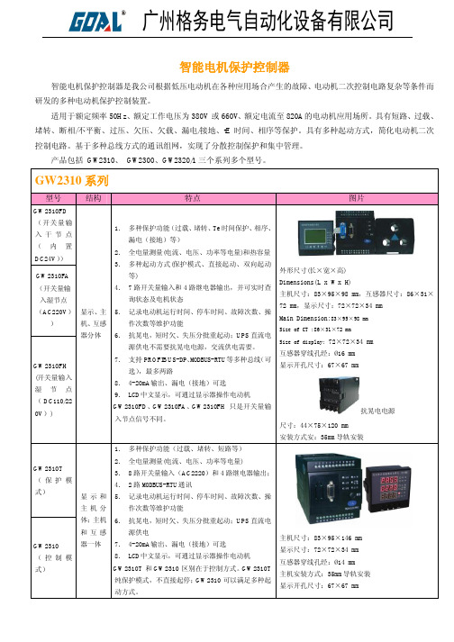
-10℃~55℃ -25℃~70℃ 20%RH~95%RH 无凝露
大气压力
80kPa~110kPa(相对海拔 2km 以下)
电磁兼容 静电放电 辐射电磁场 快速瞬变干扰
GB/T14598.14(idt IEC60255-22-2)规定的 III 级(接触放电 8kV)静电放电干扰实验 GB/T14598.9(idt IEC60255-22-3)规定的 III 级(40dB µV/m)辐射电磁场干扰实验 GB/T14598.10(idt IEC60255-22-4)规定的 III 级(通讯端口 2kV,其它端口 4kV)快速瞬变干扰实验
测量和控制数字数据通信工业控制系统用现场总线 GB/T620540.1-6-2006
类型 3:PROFIBUS 规范
测量精度
电流
电压 频率 功率因数 功率 电能 电气绝缘性能 绝缘强度 介质强度 环境条件 工作环境 储存环境 相对湿度
GW2300:±1%(≤120%Ie),±3%(120%Ie~800%Ie) GW2320/1:±1%(≤120%Ie),±3%(120%Ie~800%Ie) GW2310:±0.5%(≤120%Ie),±2.0%(120%Ie~800%Ie) GW2300:±1%;YD2310: ±0.5%; GW2310:±0.1Hz; GW2310:±1.0% ; GW2310: ±1.0%; GW2310: ±2.0%;
√ — √
— √
—
— 2路
√ —
8 路有源 — 4路
LCD 可选
√
系列
产品图片
广州格务电气自动化设备有限公司
GW2300 系列(GW2302-F、GW2302、GW2301 只是结构不同)
IP5209 datasheet v1.0 2A充电,2A放电
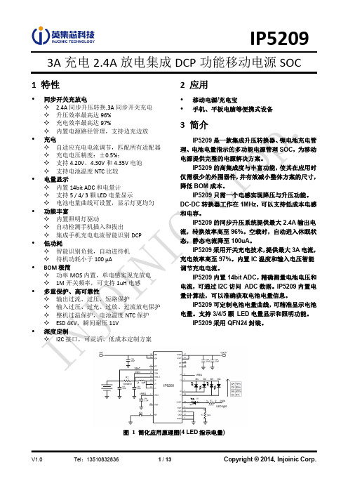
L2 亮 亮 亮 灭 灭 灭
L3 亮 亮 灭 灭 灭 灭
L4 亮 灭 灭 灭 灭 灭
灭
V1.0
Tel:13510832836
7 / 13
Copyright © 2014, Injoinic Corp.
IP5209
充电模式 4 颗 LED 显示 电量 C(%) 充满 75%≤C 50%≤C<75% 25%≤C<50% C<25% L1 亮 亮 亮 亮
按键
KEY
图 3 KEY 按键
按键连接方式如图 2 所示, 可识别长按键和短按键操作。 按键持续时间长于 30ms,但小于 2s, 即为短按动作,短按会打开电量显示灯和升压输出。 按键持续时间长于 2s, 即为长按动作, 长按会开启或者关闭照明 LED。 小于 30ms 的按键动作不会有任何响应。 在 1s 内连续两次短按键,会关闭升压输出、电量显示和照明 LEz 闪烁
L3 亮 亮
1.5Hz 闪烁
L4 亮
1.5Hz 闪烁
灭 灭 灭
灭 灭
灭
三灯、五灯的显示方式和四灯类似,每颗灯对应的电池电量如下表 D1 D2 D3 D4 D5
三颗灯 四颗灯 五颗灯
3% 25% 20%
66% 50% 40%
100% 75% 60%
无 100% 80%
IP5101 IP5105 IP5206 IP5108 IP5109 IP5209 IP5209S
V1.0
Tel:13510832836
3 / 13
Copyright © 2014, Injoinic Corp.
IP5209
6 极限参数
参数 端口输入电压范围 工作环境温度范围 结温范围 存储温度范围 热阻(结温到环境) 人体模型(HBM) 符号 VIN TA TJ Tstg θJA ESD 值 -0.3 ~ 5.5 0 ~ 70 -40 ~ 150 -60 ~ 150 40 4 单位 V ℃ ℃ ℃ ℃/W KV
