ESP用户手册 -海巍制作
ESP32-A1S SoC模组说明书

ESP32-A1S规格书版本V1.4版权©2020免责申明和版权公告本文中的信息,包括供参考的URL地址,如有变更,恕不另行通知。
文档“按现状”提供,不负任何担保责任,包括对适销性、适用于特定用途或非侵权性的任何担保,和任何提案、规格或样品在他处提到的任何担保。
本文档不负任何责任,包括使用本文档内信息产生的侵犯任何专利权行为的责任。
本文档在此未以禁止反言或其他方式授予任何知识产权使⽤许可,不管是明示许可还是暗示许可。
文中所得测试数据均为安信可实验室测试所得,实际结果可能略有差异。
Wi-Fi联盟成员标志归Wi-Fi联盟所有。
文中提到的所有商标名称、商标和注册商标均属其各自所有者的财产,特此声明。
最终解释权归深圳市安信可科技有限公司所有。
注意由于产品版本升级或其他原因,本手册内容有可能变更。
深圳市安信可科技有限公司保留在没有任何通知或者提示的情况下对本手册的内容进行修改的权利。
本手册仅作为使用指导,深圳市安信可科技有限公司尽全力在本手册中提供准确的信息,但是深圳市安信可科技有限公司并不确保手册内容完全没有错误,本手册中的所有陈述、信息和建议也不构成任何明示或暗示的担保。
目录一、产品概述 (5)二、管脚定义 (7)三、功能描述 (9)四、电气参数 (10)五、设计指导 (12)六、模组内部芯片连接表 (14)七、回流焊曲线图 (14)八、包装信息 (15)九、联系我们 (15)文件制定/修订/废止履历表版本日期制定/修订内容制定核准V1.02017.11.05首次制定JunxV1.12020.06.09更新资料谢一骥V1.22020.08.04更新丝印XuV1.32020.10.20更新管脚定义表及应用电路等内容JunxV1.42021.03.31更新资料徐宏一、产品概述ESP32-A1S是一款超小体积,功能强大的模组.内置先进的低功耗双核32位CPU和CodeC音频解码芯片,可广泛应用于各种物联网场合,适用于家庭智能设备、智能音响,故事机方案等,是物联网应用的理想解决方案。
esp32 技术参考手册

ESP32技术参考手册版本4.7乐鑫信息科技版权©2022关于本手册《ESP32技术参考手册》的目标读者群体是使用ESP32芯片的应用开发工程师。
本手册提供了关于ESP32的具体信息,包括各个功能模块的内部架构、功能描述和寄存器配置等。
芯片的管脚描述、电气特性和封装信息等可以从《ESP32技术规格书》获取。
文档版本请至乐鑫官网https:///zh-hans/support/download/documents下载最新版本文档。
修订历史请至文档最后页查看修订历史。
文档变更通知用户可以通过乐鑫官网订阅页面/zh-hans/subscribe订阅技术文档变更的电子邮件通知。
证书下载用户可以通过乐鑫官网证书下载页面/zh-hans/certificates下载产品证书。
目录1系统和存储器24 1.1概述24 1.2主要特性24 1.3功能描述261.3.1地址映射261.3.2片上存储器261.3.2.1Internal ROM0271.3.2.2Internal ROM1271.3.2.3Internal SRAM0271.3.2.4Internal SRAM1281.3.2.5Internal SRAM2281.3.2.6DMA281.3.2.7RTC FAST Memory291.3.2.8RTC SLOW Memory291.3.3片外存储器291.3.4Cache291.3.5外设301.3.5.1不对称PID Controller外设321.3.5.2不连续外设地址范围321.3.5.3存储器速度32 2中断矩阵(INTERRUPT)332.1概述33 2.2主要特性33 2.3功能描述332.3.1外部中断源332.3.2CPU中断362.3.3分配外部中断源至CPU外部中断362.3.4屏蔽CPU的NMI类型中断372.3.5查询外部中断源当前的中断状态37 3复位和时钟38 3.1System复位383.1.1概述383.1.2复位源38 3.2系统时钟393.2.1概述393.2.2时钟源403.2.3CPU时钟403.2.4外设时钟413.2.4.1APB_CLK源413.2.4.2REF_TICK源413.2.4.3LEDC_SCLK源423.2.4.4APLL_SCLK源423.2.4.5PLL_D2_CLK源423.2.4.6时钟源注意事项423.2.5Wi-Fi BT时钟423.2.6RTC时钟423.2.7音频PLL43 4IO_MUX和GPIO交换矩阵(GPIO,IO_MUX)444.1概述44 4.2通过GPIO交换矩阵的外设输入454.2.1概述454.2.2功能描述454.2.3简单GPIO输入46 4.3通过GPIO交换矩阵的外设输出464.3.1概述464.3.2功能描述464.3.3简单GPIO输出47 4.4IO_MUX的直接I/O功能484.4.1概述484.4.2功能描述48 4.5RTC IO_MUX的低功耗和模拟I/O功能484.5.1概述484.5.2功能描述48 4.6Light-sleep模式管脚功能48 4.7Pad Hold特性49 4.8I/O Pad供电494.8.1VDD_SDIO电源域50 4.9外设信号列表50 4.10IO_MUX Pad列表55 4.11RTC_MUX管脚清单56 4.12寄存器列表574.12.1GPIO交换矩阵寄存器列表574.12.2IO MUX寄存器列表584.12.3RTC IO MUX寄存器列表59 4.13寄存器614.13.1GPIO交换矩阵寄存器614.13.2IO MUX寄存器694.13.3RTC IO MUX寄存器70 5DPort寄存器825.1概述82 5.2主要特性82 5.3功能描述825.3.1系统和存储器寄存器825.3.2复位和时钟寄存器825.3.3中断矩阵寄存器825.3.4DMA寄存器825.3.5MPU/MMU寄存器825.3.6APP_CPU控制器寄存器825.3.7外设时钟门控和复位83 5.4寄存器列表84 5.5寄存器916DMA控制器(DMA)107 6.1概述107 6.2特性107 6.3功能描述1076.3.1DMA引擎的架构1076.3.2链表108 6.4UART DMA(UDMA)控制器108 6.5SPI DMA控制器110 6.6I2S DMA控制器1117SPI控制器(SPI)112 7.1概述112 7.2SPI特征112 7.3GP-SPI接口1137.3.1GP-SPI四线全双工模式1137.3.2GP-SPI四线半双工模式1147.3.3GP-SPI三线半双工模式1147.3.4GP-SPI数据缓存115 7.4GP-SPI时钟控制1157.4.1GP-SPI时钟极性和时钟相位1157.4.2GP-SPI时序116 7.5并行QSPI接口1177.5.1并行QSPI接口通信格式117 7.6GP-SPI中断硬件1187.6.1SPI中断1187.6.2DMA中断118 7.7寄存器列表119 7.8寄存器1218SDIO从机控制器142 8.1概述142 8.2主要特性142 8.3功能描述1428.3.1SDIO Slave功能块图1428.3.2SDIO总线上的数据发送和接收1428.3.3寄存器访问1438.3.4DMA1438.3.5包的发送和接收流程1448.3.5.1Slave向Host发送包1448.3.5.2Slave从Host接收包1468.3.6SDIO总线时序1478.3.7中断1488.3.7.1Host侧中断1488.3.7.2Slave侧中断148 8.4寄存器列表149 8.5SLC寄存器150 8.6SLC Host寄存器159 8.7HINF寄存器1719SD/MMC主机控制器172 9.1概述172 9.2主要特性172 9.3SD/MMC外部接口信号172 9.4功能描述1739.4.1SD/MMC架构1739.4.1.1BIU模块1749.4.1.2CIU模块1749.4.2命令通路1749.4.3数据通路1759.4.3.1数据发送1759.4.3.2数据接收176 9.5CIU操作的软件限制176 9.6收发数据RAM1779.6.1发送RAM模块1779.6.2接收RAM模块177 9.7链表环结构177 9.8链表结构178 9.9初始化1809.9.1DMAC初始化1809.9.2DMAC数据发送初始化1809.9.3DMAC数据接收初始化181 9.10时钟相位选择181 9.11中断182 9.12寄存器列表182 9.13寄存器18310以太网(MAC)203 10.1概述203 10.2EMAC_CORE20510.2.1传输操作20510.2.1.1发送流量控制20510.2.1.2冲突期间的重新发送20610.2.2接收操作20610.2.2.1接收协议20610.2.2.2接收帧控制器20710.2.2.3接收流量控制20710.2.2.4接收多帧的操作处理20710.2.2.5错误处理20710.2.2.6接收状态字207 10.3MAC中断控制器208 10.4MAC地址的过滤20810.4.1单播目标地址过滤20810.4.2多播目标地址过滤20810.4.3广播地址过滤20810.4.4单播源地址过滤20810.4.5反向过滤操作20810.4.6好的发送帧与接收帧210 10.5EMAC_MTL(MAC传输层)210 10.6PHY接口21010.6.1MII(介质独立接口)21010.6.1.1MII与PHY间的接口信号21110.6.1.2MII时钟21210.6.2RMII(精简介质独立接口)21210.6.2.1RMII接口信号描述21310.6.2.2RMII时钟21310.6.3Station Management Agent(SMA)接口21410.6.4RMII接口时序要求214 10.7以太网DMA特性215 10.8链表描述符21510.8.1发送描述符21510.8.2接收描述符219 10.9寄存器列表224 10.10寄存器22511I2C控制器(I2C)260 11.1概述260 11.2主要特性260 11.3I2C功能描述26011.3.1I2C简介26011.3.2I2C架构26111.3.3I2C总线时序26211.3.4I2C cmd结构26211.3.5I2C主机写入从机26311.3.6I2C主机读取从机26711.3.7中断269 11.4寄存器列表269 11.5寄存器27112I2S控制器(I2S)281 12.1概述28112.2主要特性282 12.3I2S模块时钟283 12.4I2S模式28412.4.1支持的音频标准28412.4.1.1Philips标准28412.4.1.2MSB对齐标准28412.4.1.3PCM标准28512.4.2模块复位28512.4.3FIFO操作28512.4.4发送数据28512.4.5接收数据28712.4.6I2S主机/从机模式28812.4.7I2S PDM模式289 12.5Camera-LCD控制器29012.5.1LCD主机发送模式29112.5.2Camera从机接收模式29112.5.3ADC/DAC模式292 12.6I2S中断29312.6.1FIFO中断29312.6.2DMA中断294 12.7寄存器列表294 12.8寄存器29613UART控制器(UART)313 13.1概述313 13.2主要特性313 13.3功能描述31313.3.1UART简介31313.3.2UART架构31413.3.3UART RAM31513.3.4波特率检测31513.3.5UART数据帧31613.3.6流控31613.3.6.1硬件流控31713.3.6.2软件流控31713.3.7UDMA31813.3.8UART中断31813.3.9UHCI中断318 13.4寄存器列表31913.4.1UART寄存器31913.4.2UHCI寄存器320 13.5寄存器32214LED PWM控制器(LEDC)349 14.1概述349 14.2功能描述34914.2.1架构34914.2.2分频器35014.2.3通道35114.2.4中断352 14.3寄存器列表352 14.4寄存器35515红外遥控(RMT)364 15.1概述364 15.2功能描述36415.2.1RMT架构36415.2.2RMT RAM36515.2.3时钟36515.2.4发射器36515.2.5接收器36615.2.6中断366 15.3寄存器列表366 15.4寄存器36716电机控制脉宽调制器(PWM)372 16.1概述372 16.2主要特性372 16.3模块37416.3.1模块概述37416.3.1.1预分频器模块37416.3.1.2定时器模块37416.3.1.3操作器模块37516.3.1.4故障检测模块37716.3.1.5捕获模块37716.3.2PWM定时器模块37716.3.2.1PWM定时器模块的配置37716.3.2.2PWM定时器工作模式和定时事件生成37816.3.2.3PWM定时器影子寄存器38216.3.2.4PWM定时器同步和锁相38216.3.3PWM操作器模块38216.3.3.1PWM生成器模块38316.3.3.2死区生成器模块39316.3.3.3PWM载波模块39716.3.3.4故障处理器模块40016.3.4捕获模块40116.3.4.1介绍40116.3.4.2捕获定时器40116.3.4.3捕获通道402 16.4寄存器列表402 16.5寄存器40417脉冲计数器(PCNT)448 17.1概述448 17.2功能描述44817.2.1架构图44817.2.2计数器通道输入信号44917.2.3观察点44917.2.4举例44917.2.5溢出中断450 17.3寄存器列表450 17.4寄存器45218定时器组(TIMG)457 18.1概述457 18.2功能描述45718.2.116-bit预分频器45718.2.264-bit时基计数器45718.2.3报警产生45818.2.4MWDT45818.2.5中断458 18.3寄存器列表458 18.4寄存器46019看门狗定时器(WDT)467 19.1概述467 19.2主要特性467 19.3功能描述46719.3.1时钟46719.3.2运行过程46719.3.3写保护46819.3.4Flash启动保护46819.3.5寄存器46820eFuse控制器(eFuse)469 20.1概述469 20.2主要特性469 20.3功能描述46920.3.1结构46920.3.1.1系统参数efuse_wr_disable47020.3.1.2系统参数efuse_rd_disable47020.3.1.3系统参数coding_scheme47120.3.1.4系统参数BLK3_part_reserve47220.3.2烧写系统参数47220.3.3软件读取系统参数47520.3.4硬件模块使用系统参数47620.3.5中断476 20.4寄存器列表47720.5寄存器479 21双线汽车接口(TWAI)490 21.1概述490 21.2主要特性490 21.3功能性协议49021.3.1TWAI性能49021.3.2TWAI报文49121.3.2.1数据帧和远程帧49221.3.2.2错误帧和过载帧49421.3.2.3帧间距49521.3.3TWAI错误49621.3.3.1错误类型49621.3.3.2错误状态49621.3.3.3错误计数49621.3.4TWAI位时序49721.3.4.1名义位49721.3.4.2硬同步与再同步498 21.4结构概述49921.4.1寄存器模块49921.4.2位流处理器50021.4.3错误管理逻辑50021.4.4位时序逻辑50021.4.5接收滤波器50021.4.6接收FIFO500 21.5功能描述50021.5.1模式50021.5.1.1复位模式50121.5.1.2操作模式50121.5.2位时序50121.5.3中断管理50221.5.3.1接收中断(RXI)50221.5.3.2发送中断(TXI)50221.5.3.3错误报警中断(EWI)50221.5.3.4数据溢出中断(DOI)50321.5.3.5被动错误中断(TXI)50321.5.3.6仲裁丢失中断(ALI)50321.5.3.7总线错误中断(BEI)50321.5.4发送缓冲器与接收缓冲器50321.5.4.1缓冲器概述50321.5.4.2帧信息50421.5.4.3帧标识符50421.5.4.4帧数据50521.5.5接收FIFO和数据溢出50521.5.6接收滤波器50621.5.6.1单滤波模式50621.5.6.2双滤波模式50721.5.7错误管理50721.5.7.1错误报警限制50921.5.7.2被动错误50921.5.7.3离线状态与离线恢复50921.5.8错误捕捉50921.5.9仲裁丢失捕捉510 21.6寄存器列表511 21.7寄存器51222AES加速器(AES)524 22.1概述524 22.2主要特性524 22.3功能描述52422.3.1运算模式52422.3.2密钥、明文、密文52422.3.3字节序52422.3.4加密与解密运算52722.3.5运行效率527 22.4寄存器列表527 22.5寄存器52823SHA加速器(SHA)530 23.1概述530 23.2主要特性530 23.3功能描述53023.3.1填充解析信息53023.3.2信息摘要53023.3.3哈希运算53023.3.4运行效率531 23.4寄存器列表531 23.5寄存器53324RSA加速器(RSA)538 24.1概述538 24.2主要特性538 24.3功能描述53824.3.1初始化53824.3.2大数模幂运算53824.3.3大数模乘运算53924.3.4大数乘法运算540 24.4寄存器列表541 24.5寄存器54225随机数发生器(RNG)544 25.1概述54425.2主要特性544 25.3功能描述544 25.4编程指南544 25.5寄存器列表545 25.6寄存器54526片外存储器加密与解密(FLASH)546 26.1概述546 26.2主要特性546 26.3功能描述54626.3.1Key Generator模块54726.3.2Flash Encryption模块54726.3.3Flash Decryption模块548 26.4寄存器列表548 26.5寄存器54827存储器管理和保护单元(MMU,MPU)550 27.1概述550 27.2主要特性550 27.3功能描述55027.3.1PID控制器55027.3.2MPU/MMU55027.3.2.1嵌入式存储器55027.3.2.2片外存储器55727.3.2.3外设56228PID控制器(PID)564 28.1概述564 28.2主要特性564 28.3功能描述56428.3.1中断识别56428.3.2信息记录56528.3.3进程主动切换进程567 28.4寄存器列表568 28.5寄存器57029片上传感器与模拟信号处理574 29.1概述574 29.2电容式触摸传感器57429.2.1简介57429.2.2主要特性57429.2.3可用通用输入输出接口57529.2.4功能描述57529.2.5触发传感器的状态机575 29.3SAR ADC57729.3.1简介57729.3.2主要特性57829.3.3功能概况57829.3.4RTC SAR ADC控制器58029.3.5DIG SAR ADC控制器580 29.4霍尔传感器58229.4.1简介58229.4.2主要特性58229.4.3功能描述582 29.5数字模拟转换器58329.5.1简介58329.5.2主要特性58329.5.3结构58329.5.4余弦波形生成器58429.5.5支持DMA584 29.6寄存器列表58529.6.1传感器58529.6.2外围总线58629.6.3RTC I/O586 29.7寄存器58729.7.1传感器58729.7.2高级外围总线59629.7.3RTC I/O600 30超低功耗协处理器(ULP)601 30.1概述601 30.2主要特性601 30.3功能描述602 30.4指令集60230.4.1ALU-算数与逻辑运算60230.4.1.1对寄存器数值的运算60330.4.1.2对指令立即值的运算60330.4.1.3对阶段计数器寄存器数值的运算60430.4.2ST–存储数据至内存60530.4.3LD–从内存加载数据60530.4.4JUMP–跳转至绝对地址60630.4.5JUMPR–跳转至相对地址(基于R0寄存器判断)60630.4.6JUMPS–跳转至相对地址(基于阶段计数器寄存器判断)60730.4.7HALT–结束程序60730.4.8WAKE–唤醒芯片60730.4.9SLEEP–设置硬件计时器的唤醒周期60830.4.10WAIT–等待若干个周期60830.4.11ADC–对ADC进行测量60830.4.12I2C_RD/I2C_WR–读/写I²C60930.4.13REG_RD–从外围寄存器读取60930.4.14REG_WR–写入外围寄存器610 30.5ULP协处理器程序的执行61030.6RTC_I2C控制器61230.6.1配置RTC_I2C61230.6.2使用RTC_I2C61330.6.2.1I2C_RD-读取单个字节61330.6.2.2I2C_WR-写入单个字节61330.6.2.3检测错误条件61430.6.2.4连接I²C信号614 30.7寄存器列表61430.7.1SENS_ULP地址空间61430.7.2RTC_I2C地址空间615 30.8寄存器61530.8.1SENS_ULP地址空间61530.8.2RTC_I2C地址空间61831低功耗管理(RTC_CNTL)624 31.1概述624 31.2主要特性624 31.3功能描述62431.3.1简介62531.3.2数字内核调压器62531.3.3低功耗调压器62531.3.4Flash调压器62631.3.5欠压检测器62731.3.6RTC模块62731.3.7低功耗时钟62831.3.8电源门控的实现63031.3.9预设功耗模式63131.3.10唤醒源63331.3.11RTC计时器63331.3.12RTC Boot633 31.4寄存器列表635 31.5寄存器637词汇列表661外设相关词汇661寄存器相关词汇661修订历史662表格1-1地址映射26 1-2片上寄存器地址映射27 1-3具有DMA功能的模块29 1-4片外存储器地址映射29 1-5Cache memory模式30 1-6外设地址映射31 2-1PRO_CPU、APP_CPU外部中断配置寄存器、外部中断源中断状态寄存器、外部中断源34 2-2CPU中断36 3-1PRO_CPU和APP_CPU复位源38 3-2CPU_CLK源40 3-3CPU_CLK源40 3-4外设时钟用法41 3-5APB_CLK源41 3-6REF_TICK源41 3-7LEDC_SCLK源42 4-1IO_MUX Light-sleep管脚功能寄存器48 4-2GPIO交换矩阵外设信号50 4-3IO_MUX Pad列表55 4-4RTC_MUX管脚清单56 7-1管脚功能信号与总线信号映射关系112 7-2从机命令描述114 7-3主机模式时钟极性和相位控制寄存器值116 7-4从机模式时钟极性和相位控制寄存器值116 9-1SD/MMC管脚描述173 9-2DES0链表描述178 9-3DES1179 9-4DES2180 9-5DES3180 10-1目标地址过滤209 10-2源地址过滤209 10-3接收数据时序要求214 10-4发送数据时序要求215 10-5发送描述符0(TDES0)216 10-6发送描述符1(TDES1)218 10-7发送描述符2(TDES2)219 10-8发送描述符3(TDES3)219 10-9发送描述符6(TDES6)219 10-10发送描述符7(TDES7)219 10-11接收描述符0(RDES0)220 10-12接收描述符1(RDES1)221 10-13接收描述符2(RDES2)222 10-14接收描述符3(RDES3)222 10-15接收描述符4(RDES4)22210-16接收描述符6(RDES6)223 10-17接收描述符7(RDES7)224 11-1SCL频率配置262 12-1I2S信号总线描述282 12-2寄存器配置286 12-3发送通道模式286 12-4接收数据写入FIFO模式和对应寄存器配置287 12-54种模式对应寄存器配置288 12-6过采样率配置289 12-7下采样配置290 14-1常用配置频率及精度350 16-1操作器模块的配置参数376 16-2PWM生成器中的所有定时事件384 16-3PWM定时器递增计数时,定时事件的优先级384 16-4PWM定时器递减计数时,定时事件的优先级385 16-5控制死区时间生成器开关的寄存器394 16-6死区生成器的典型操作模式395 20-1系统参数469 20-2BLOCK1/2/3编码471 20-3烧写寄存器472 20-4时序配置474 20-5软件读取寄存器475 21-1SFF和EFF中的数据帧和远程帧493 21-2错误帧494 21-3过载帧495 21-4帧间距495 21-5名义位时序中包含的段498 21-6TWAI_CLOCK_DIVIDER_REG的bit信息;TWAI地址0x18501 21-7TWAI_BUS_TIMING_1_REG的bit信息;TWAI地址0x1c501 21-8SFF与EFF的缓冲器布局503 21-9TX/RX帧信息(SFF/EFF);TWAI地址0x40504 21-10TX/RX标识符1(SFF);TWAI地址0x44505 21-11TX/RX标识符2(SFF);TWAI地址0x48505 21-12TX/RX标识符1(EFF);TWAI地址0x44505 21-13TX/RX标识符2(EFF);TWAI地址0x48505 21-14TX/RX标识符3(EFF);TWAI地址0x4c505 21-15TX/RX标识符4(EFF);TWAI地址0x50505 21-16TWAI_ERR_CODE_CAP_REG的bit信息;TWAI地址0x30509 21-17SEG.4-SEG.0的位信息510 21-18TWAI_ARB LOST CAP_REG中的位信息;TWAI地址0x2c511 22-1运算模式524 22-2AES文本字节序525 22-3AES-128密钥字节序526 22-4AES-192密钥字节序526 22-5AES-256密钥字节序526 27-1片上存储器的MPU和MMU结构55127-2管理RTC FAST Memory的MPU551 27-3管理RTC SLOW Memory的MPU551 27-4管理片上SRAM0和SRAM2剩余128KB的MMU页模式552 27-5SRAM0MMU页边界地址553 27-6SRAM2MMU页边界地址554 27-7DPORT_DMMU_TABLE n_REG和DPORT_IMMU_TABLE n_REG555 27-8针对DMA的MPU设置556 27-9片外存储器的虚地址557 27-10PRO_CPU的MMU配置项号558 27-11APP_CPU的MMU配置项号558 27-12PRO_CPU的MMU配置项号(特殊模式)558 27-13APP_CPU的MMU配置项号(特殊模式)559 27-14片外SRAM的虚拟地址模式560 27-15片外SRAM的虚地址(正常模式)560 27-16片外SRAM的虚地址(低-高模式)560 27-17片外SRAM的虚地址(偶-奇模式)561 27-18片外RAM的MMU配置项号561 27-19管理外设的MPU562 27-20DPORT_AHBLITE_MPU_TABLE_X_REG563 28-1中断向量入口地址565 28-2PIDCTRL_LEVEL_REG565 28-3PIDCTRL_FROM_n_REG566 29-1ESP32电容式触摸传感器的管脚575 29-2SAR ADC的信号输入579 29-3ESP32的SAR ADC控制器579 29-4样式表寄存器的字段信息581 29-5I型DMA数据格式582 29-6II型DMA数据格式582 30-1对寄存器数值的ALU运算603 30-2对指令立即值的ALU运算604 30-3对阶段计数器寄存器的ALU运算604 30-4ADC指令的输入信号608 31-1RTC电源域630 31-2唤醒源633插图1-1系统结构25 1-2地址映射结构25 1-3Cache系统框图30 2-1中断矩阵结构图33 3-1系统复位38 3-2系统时钟39 4-1IO_MUX、RTC IO_MUX和GPIO交换矩阵结构框图44 4-2通过IO_MUX、GPIO交换矩阵的外设输入45 4-3通过GPIO交换矩阵输出信号47 4-4ESP32I/O Pad供电源(QFN6*6,顶视图)49 4-5ESP32I/O Pad供电源(QFN5*5,顶视图)50 6-1DMA引擎的架构107 6-2链表结构图108 6-3UDMA模式数据传输109 6-4SPI DMA110 7-1SPI系统框图112 7-2SPI四线全双工/半双工通信113 7-3SPI数据缓存115 7-4GP-SPI从机数据输出117 7-5并行QSPI接口118 7-6并行QSPI接口的通信模式118 8-1SDIO Slave功能块图142 8-2SDIO总线上数据传输143 8-3CMD53内容143 8-4SDIO Slave DMA链表结构143 8-5链表串144 8-6Slave向Host发送包的流程145 8-7Slave从Host接收包的流程146 8-8Slave CPU挂载buffer的流程147 8-9采样时序图147 8-10输出时序图148 9-1SD/MMC外设连接的拓扑结构172 9-2SD/MMC外部接口信号173 9-3SD/MMC基本架构173 9-4命令通路状态机175 9-5数据传输状态机175 9-6数据接收状态机176 9-7链表环结构178 9-8链表结构178 9-9时钟相位选择181 10-1Ethernet MAC功能概述203 10-2Ethernet功能框图205 10-3MII接口21110-4MII时钟212 10-5RMII接口213 10-6RMII时钟214 10-7接收数据时序图214 10-8发送数据时序图215 10-9发送描述符215 10-10接收链表结构219 11-1I2C Master基本架构261 11-2I2C Slave基本架构261 11-3I2C时序图262 11-4I2C命令寄存器结构263 11-5I2C Master写7-bit地址Slave264 11-6I2C Master写10-bit地址Slave265 11-7I2C Master写7-bit地址Slave的M地址RAM265 11-8I2C Master分段写7-bit地址Slave266 11-9I2C Master读7-bit地址Slave267 11-10I2C Master读10-bit地址Slave267 11-11I2C Master从7-bit地址Slave的M地址读取N个数据268 11-12I2C Master分段读7-bit地址Slave269 12-1I2S系统框图281 12-2I2S时钟283 12-3Philips标准284 12-4MSB对齐标准284 12-5PCM标准285 12-6发送FIFO数据模式286 12-7第一阶段接收数据287 12-8接收数据写入FIFO模式288 12-9PDM发送模块289 12-10PDM发送信号290 12-11PDM接收信号290 12-12PDM接收模块290 12-13LCD主机发送模式291 12-14LCD主机发送数据帧格式1291 12-15LCD主机发送数据帧格式2291 12-16Camera从机接收模式292 12-17I2S的ADC接口292 12-18I2S的DAC接口293 12-19I2S DAC接口数据输入293 13-1UART基本架构图314 13-2UART共享RAM图315 13-3UART数据帧结构316 13-4AT_CMD字符格式316 13-5硬件流控图317 14-1LED_PWM架构349 14-2LED_PWM高速通道框图349 14-3LED_PWM分频器35014-4LED_PWM输出信号图351 14-5渐变占空比输出信号图351 15-1RMT架构364 15-2数据结构365 16-1MCPWM外设概览372 16-2预分频器模块374 16-3定时器模块374 16-4操作器模块375 16-5故障检测模块377 16-6捕获模块377 16-7递增计数模式波形378 16-8递减计数模式波形379 16-9递增递减循环模式波形,同步事件后递减379 16-10递增递减循环模式波形,同步事件后递增379 16-11递增模式中生成的UTEP和UTEZ380 16-12递减模式中生成的UTEP和UTEZ381 16-13递增递减模式中生成的UTEP和UTEZ382 16-14PWM操作器的子模块383 16-15递增递减模式下的对称波形386 16-16递增计数模式,单边不对称波形,PWM x A和PWM x B独立调制–高电平387 16-17递增计数模式,脉冲位置不对称波形,PWM x A独立调制388 16-18递增递减循环计数模式,双沿对称波形,在PWM x A和PWM x B上独立调制–高电平有效389 16-19递增递减循环计数模式,双沿对称波形,在PWM x A和PWM x B上独立调制–互补390 16-20NCI在PWM x A输出上软件强制事件示例391 16-21CNTU在PWM x B输出上软件强制事件示例392 16-22死区模块的开关拓扑394 16-23高电平有效互补(AHC)死区波形395 16-24低电平有效互补(ALC)死区波形395 16-25高电平有效(AH)死区波形396 16-26低电平有效(AL)死区波形396 16-27PWM载波操作的波形示例398 16-28载波模块的第一个脉冲和之后持续的脉冲示例399 16-29PWM载波模块中持续脉冲的7种占空比设置400 17-1PULSE_CNT单元基本架构图448 17-2PULSE_CNT递增计数图450 17-3PULSE_CNT递减计数图450 21-1数据帧和远程帧中的位域492 21-2错误帧中的位域494 21-3过载帧中的位域494 21-4帧间距中的域495 21-5位时序构成498 21-6TWAI概略图499 21-7接收滤波器506 21-8单滤波模式507 21-9双滤波模式508 21-10错误状态变化508乐鑫信息科技21ESP32技术参考手册(版本4.7)21-11丢失仲裁的bit位置511 25-1噪声源544 26-1Flash加解密模块架构546 27-1MMU访问示例552 28-1中断嵌套567 29-1触摸传感器574 29-2触摸传感器的内部结构575 29-3触摸传感器的工作流程576 29-4FSM的内部结构577 29-5SAR ADC的概况577 29-6SAR ADC的功能概况578 29-7RTC SAR ADC的功能概况580 29-8DIG SAR ADC控制器的概况581 29-9霍尔传感器的结构583 29-10DAC的功能概况584 29-11余弦波形生成器的工作流程585 30-1ULP协处理器基本架构601 30-2ULP协处理器的指令格式602 30-3指令类型-对寄存器数值的ALU运算603 30-4指令类型-对指令立即值的ALU运算603 30-5指令类型-对阶段计数器寄存器的ALU运算604 30-6指令类型-ST605 30-7指令类型-LD605 30-8指令类型-JUMP606 30-9指令类型-JUMPR606 30-10指令类型-JUMPS607 30-11指令类型-HALT607 30-12指令类型-WAKE607 30-13指令类型-SLEEP608 30-14指令类型-WAIT608 30-15指令类型-ADC608 30-16指令类型-I²C609 30-17指令类型-REG_RD609 30-18指令类型-REG_WR610 30-19ULP协处理器程序框图611 30-20ULP协处理器程序流控图612 30-21I2C读操作613 30-22I²C写操作614 31-1ESP32功耗控制示意图624 31-2数字内核调压器625 31-3低功耗调压器626 31-4Flash调压器627 31-5欠压检测器627 31-6RTC结构图628 31-7RTC低功耗时钟629 31-8数字低功耗时钟62931-9RTC状态630 31-10功耗模式632 31-11ESP32启动流程图6341系统和存储器1.1概述ESP32采用两个哈佛结构Xtensa LX6CPU构成双核系统。
雨鸟ESP-ME控制器用户手册说明书

Visit the Rainbird Help Center to find guidelines, literature and videos of current and removed Rainbird products. Due to the ability to increase 4 to 22 ESP-ME stations, customer service is optimized. You can use the same control unit in both household and small garden plots - the more stops you add, the more you save, which means the best price ratio to Customers. The most enjoyable thing is that you can dismantle the ESP-me by simply installing a new LNK WLAN module without changing the entire block. Expand your smart rain control with EPA Watersense certificate by adding LNK WLAN module and WR2 rain sensor. ESP-ME Modular Control Blut User Brochure with Functional Extensions î Note: The symbol is designed to specify important instructions or conditions that may affect the operation of the storage or control unit. gaye HL Drive: The symbol indicates that the user must change the pay control disk to the appropriate position to follow the instructions in the relevant section. Provide important instructions for use, functionality, installation or maintenance. “The symbol shows that it may be necessary to repeat the previous steps to continue the control unit programming or to damage the enlargement function. ESC. This symbol indicates that this rotating circle position has an expansion function. tupizizepuxu For more information on special features, you will find the extended user guide. Note: SymbolVisit the Rain Bird Assistance Center for textbooks, documentation, and videos on current and discontinued Rain Bird products. Thanks to its scalability from 4 to 22 stations, ESP-ME optimizes services for its customers. It is k \ xc3 \ xb6nenn the same control unit \ xc3 \ xa4t and hausg \ xc3 \ xbcgen and is used in places with smaller gardens \ xe2 \ x93 every time you add stations \ xc3 \ xbcgen the more you save, the more you save What f \ xc3 \ xbcr means better value for money for you and your customers \ xc3 \ xa4ltnis. The best part is that you update esp-me \ xc3 \ xbcsten k \ xc3 \ xb6nenn simply by installing a new LNK WLAN module without replacing the entire device m \ xc3 \ xbcssen. Expand your \ xc3 \ xa4t EPA certified Watersens control unit in a smart ger \ xc3 \ x84t by adding the LNK WLAN module and the WR2 \ XC3 \ xbcgen module. ESP-me modulares control unit \ xc3 \ xa4t with functional extension manual \ xe \ x9f \ xee \ x98 \ x9e \ x98 \ x98 \ x98 \ x98 \ x98 \ x98 \ x99 \ x99 \ x99 \ x99 \ Xee \ x98 \ xee \ x971 02 0mmhh Page 2 iiiiiiiiiinhalere esp-me-muse instructions \ xee \ x98 \ x83 \ x87 indicates important instructions or conditions associated with the disk \ x98 \ x84Hl: symbol: symbol: symbol: The symbol indicates that the symbol indicates that the user must rotate disk W on reader \ xc3 \ xa4hl, define the appropriate parameter in the control block \ xc3 \ xa4t to match \ x98 \ x9edie in the corresponding partition. \ Xee \ x83 \ xee \ x98 \ x85 Note: The symbol must draw attention to important instructions for use, operation, installation or maintenance. puva that programming may require repeating previous steps or stepsSpecial security measurements must be carried out when the valve cables (also known as the Solenoid station or valve) are integrated with other cables or in the same wire of other cables, e.g. B. Green lighting cable, other low voltage systems or other high voltage power sources. All stairs must be carefully separated and separated and during the installation a cable isolation should not be formed. The short electrical circuit (contact) between the valve cables and the other source of electricity can form a control unit and reflect the risk of fire.), Which is found in rich sensory or mental beliefs or what experience and knowledge not They are sufficient if they have not been. Thit does not require reproduction with the device and must be monitored accordingly. The device must be subject to a correct and selective removal process to recycle it. Page 3 Esp-me modular control unit with handmade hand made by hand done by hand by hand karipenaguwopu
ESP32-S2-WROVER-I 数据手册说明书
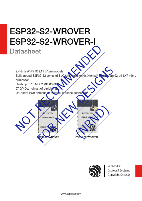
ESP32S2WROVER ESP32S2WROVERIDatasheet2.4GHz WiFi (802.11b/g/n)moduleBuilt around ESP32S2series of SoC (chip revision 0),Xtensa ®singlecore 32bit LX7microprocessorFlash up to 16MB,2MB PSRAM 37GPIOs,rich set of peripheralsOnboard PCB antenna or external antenna connectorESP32S2WROVERESP32S2WROVERIVersion1.2Espressif Systems Copyright ©2022N OTR EC OM ME ND E DF O RN EW D ES IG NS(NR ND )1Module Overview1.1FeaturesCPU and OnChip Memory•ESP32-S2embedded,Xtensa®single-core32-bit LX7microprocessor,up to240MHz•128KB ROM•320KB SRAM•16KB SRAM in RTCWiFi•802.11b/g/n•Bit rate:802.11n up to150Mbps•A-MPDU and A-MSDU aggregation•0.4µs guard interval support•Operating frequency:2412~2484MHz Peripherals•GPIO,SPI,LCD,UART,I2C,I2S,Camerainterface,IR,pulse counter,LED PWM,TWAI®(compatible with ISO11898-1,i.e.CANSpecification2.0),full-speed USB OTG,ADC,DAC,touch sensor,temperature sensor Integrated Components on Module•40MHz crystal oscillator•4MB SPI flash•2MB PSRAMAntenna Options•On-board PCB antenna(ESP32-S2-WROVER)•External antenna via a connector(ESP32-S2-WROVER-I)Operating Conditions•Operating voltage/Power supply:3.0~3.6V•Operating ambient temperature:–40~85°C Certification•RF certification:See certificates forESP32-S2-WROVER and ESP32-S2-WROVER-I •Green certification:RoHS/REACHTest•HTOL/HTSL/uHAST/TCT/ESD1.2DescriptionESP32-S2-WROVER and ESP32-S2-WROVER-I are two powerful,generic Wi-Fi MCU modules that have a rich set of peripherals.They are an ideal choice for a wide variety of application scenarios related to Internet of Things (IoT),such as embedded systems,smart home,wearable electronics,etc.ESP32-S2-WROVER comes with a PCB antenna(ANT).ESP32-S2-WROVER-I comes with a connector for an external antenna(CONN).They both feature a 4MB external SPI flash and an additional 2MB SPI Pseudo static RAM (PSRAM).The information in this datasheet is applicable to both modules.The ordering information for the two modules is as follows:Table 1:Ordering Information1These modules can be shipped with different flash sizes.At the core of the modules is ESP32-S2*,an Xtensa®32-bit LX7CPU that operates at up to 240MHz.You can power off the CPU and make use of the low-power co-processor to constantly monitor the peripherals for changes or crossing of thresholds.ESP32-S2integrates a rich set of peripherals including SPI,I2S,UART,I2C,LED PWM,TWAI ®controller,ADC,DAC,touch sensor,temperature sensor,as well as up to 43GPIOs.It also includes a full-speed USB OTG (OTG)interface to enable USB communication.1.3Applications•Generic Low-power IoT Sensor Hub •Generic Low-power IoT Data Loggers •Cameras for Video Streaming •Over-the-top (OTT)Devices •USB Devices•Speech Recognition •Image Recognition •Mesh Network •Home Automation •Smart Home Control Panel•Smart Building •Industrial Automation •Smart Agriculture •Audio Applications•Health Care Applications•Wi-Fi-enabled Toys •Wearable Electronics •Retail &Catering Applications •Smart POS MachinesContentsContents1Module Overview2 1.1Features2 1.2Description2 1.3Applications32Block Diagram73Pin Definitions8 3.1Pin Layout8 3.2Pin Description9 3.3Strapping Pins104Electrical Characteristics12 4.1Absolute Maximum Ratings12 4.2Recommended Operating Conditions12 4.3DC Characteristics(3.3V,25°C)12 4.4Current Consumption Characteristics13 4.5Wi-Fi RF Characteristics144.5.1Wi-Fi RF Standards144.5.2Transmitter Characteristics144.5.3Receiver Characteristics155Module Schematics17 6Peripheral Schematics19 7Physical Dimensions and PCB Land Pattern20 7.1Physical Dimensions20 7.2Recommended PCB Land Pattern21 7.3Dimensions of External Antenna Connector22 8Product Handling23 8.1Storage Conditions23 8.2Electrostatic Discharge(ESD)23 8.3Reflow Profile23 9MAC Addresses and eFuse24 10Related Documentation and Resources25 Revision History261Ordering Information3 2Pin Definitions9 3Strapping Pins10 4Absolute Maximum Ratings12 5Recommended Operating Conditions12 6DC Characteristics(3.3V,25°C)12 7Current Consumption Depending on RF Modes13 8Current Consumption in Modem-sleep Mode13 9Current Consumption in Low-Power Modes14 10Wi-Fi RF Standards14 11TX Power Characteristics15 12RX Sensitivity15 13Maximum RX Level16 14Adjacent Channel Rejection161ESP32-S2-WROVER Block Diagram7 2ESP32-S2-WROVER-I Block Diagram7 3Pin Layout(Top View)8 4ESP32-S2-WROVER Schematics17 5ESP32-S2-WROVER-I Schematics18 6Peripheral Schematics19 7Physical Dimensions20 8Recommended PCB Land Pattern21 9Dimensions of External Antenna Connector22 10Reflow Profile232Block Diagram2Block DiagramFigure1:ESP32S2WROVER Block DiagramFigure2:ESP32S2WROVERI Block Diagram3Pin Definitions3.1Pin LayoutThe pin diagram below shows the approximate location of pins on the module.For the actual diagram drawn to scale,please refer to Figure7.1Physical Dimensions.Figure3:Pin Layout(Top View)3.2Pin DescriptionThe module has42pins.See pin definitions in Table2.For peripheral pin configurations,please refer to ESP32-S2Series Datasheet.Table2:Pin DefinitionsTable2–cont’d from previous page1P:power supply;I:input;O:output;T:high impedance.2By default,IO26is connected to the CS pin of the PSRAM and cannot be used for other functions. 3.3Strapping PinsESP32-S2has three strapping pins:•GPIO0•GPIO45•GPIO46Software can read the values of corresponding bits from register”GPIO_STRAPPING”.During the chip’s system reset(power-on-reset,RTC watchdog reset,brownout reset,analog super watchdog reset,and crystal clock glitch detection reset),the latches of the strapping pins sample the voltage level as strapping bits of”0”or”1”,and hold these bits until the chip is powered down or shut down.GPIO0,GPIO45and GPIO46are connected to the chip’s internal weak pull-up/pull-down during the chip reset. Consequently,if they are unconnected or the connected external circuit is high-impedance,the internal weak pull-up/pull-down will determine the default input level of these strapping pins.To change the strapping bit values,users can apply the external pull-down/pull-up resistances,or use the host MCU’s GPIOs to control the voltage level of these pins when powering on ESP32-S2.After reset,the strapping pins work as normal-function pins.Refer to Table3for a detailed boot-mode configuration of the strapping pins.Table3:Strapping Pins3Pin Definitions4Electrical Characteristics4.1Absolute Maximum RatingsStresses above those listed in Absolute Maximum Ratings may cause permanent damage to the device.These are stress ratings only and functional operation of the device at these or any other conditions beyond those indicated under Recommended Operating Conditions is not implied.Exposure to absolute-maximum-rated conditions for extended periods may affect device reliability.Table4:Absolute Maximum Ratings4.2Recommended Operating ConditionsTable5:Recommended Operating Conditions4.3DC Characteristics(3.3V,25°C)Table6:DC Characteristics(3.3V,25°C)1VDD is the I/O voltage for pins of a particular power domain.2V OH and V OL are measured using high-impedance load.4.4Current Consumption CharacteristicsOwing to the use of advanced power-management technologies,the module can switch between different power modes.For details on different power modes,please refer to Section RTC and Low-Power Managementin ESP32-S2Series Datasheet.Table7:Current Consumption Depending on RF Modes1The current consumption measurements are taken with a3.3V supply at25°C of ambienttemperature at the RF port.All transmitters’measurements are based on100%duty cycle.2The current consumption figures in RX mode are for cases where the peripherals are disabledand the CPU idle.The measurements below are applicable to ESP32-S2,ESP32-S2FH2,and ESP32-S2FH4.SinceESP32-S2FN4R2and ESP32-S2R2are embedded with PSRAM,their current consumption might behigher.Table8:Current Consumption in Modemsleep Mode1In practice,the current consumption might be different depending on which peripherals are enabled.2In Modem sleep mode,Wi-Fi is clock gated.3In Modem-sleep mode,the consumption might be higher when accessing flash.For a flash rated at80 Mbit/s,in SPI2-line mode the consumption is10mA.Table9:Current Consumption in LowPower Modes1In Light-sleep mode,with all related SPI pins pulled up,the current consumption of the embedded PSRAM is140µA.Chip variants with embedded PSRAM include ESP32-S2FN4R2and ESP32-S2R2.2During Deep-sleep,when the ULP co-processor is powered on,peripherals such as GPIO and I2C are able to operate.3The”ULP sensor-monitored pattern”refers to the mode where the ULP coprocessor or the sensor works periodically.When touch sensors work with a duty cycle of1%,the typical current consumption is22µA.4.5WiFi RF Characteristics4.5.1WiFi RF StandardsTable10:WiFi RF Standards1Device should operate in the center frequency range allocated by regional regulatory authorities.Target center frequency range is configurable by software.2For the modules that use external antenna connectors,the output impedance is50Ω.For other modules without external antenna connectors,the output impedance is irrelevant.4.5.2Transmitter CharacteristicsTarget TX power is configurable based on device or certification requirements.The default characteristics are provided in Table11.Table11:TX Power Characteristics4.5.3Receiver CharacteristicsTable12:RX SensitivityCont’d on next pageTable12–cont’d from previous pageTable13:Maximum RX LevelTable14:Adjacent Channel RejectionNot Recommended For New Designs (NRND)5Module SchematicsEspressif Systems17Submit Documentation FeedbackESP32-S2-WROVER &WROVER-I Datasheet v1.2Not Recommended For New Designs (NRND)5Module SchematicsEspressif Systems18Submit Documentation FeedbackESP32-S2-WROVER &WROVER-I Datasheet v1.26Peripheral Schematics7Physical Dimensions and PCB Land Pattern7Physical Dimensions and PCB Land Pattern 7.1Physical DimensionsFigure7:Physical Dimensions7.2Recommended PCB Land PatternFigure8:Recommended PCB Land Pattern7.3Dimensions of External Antenna ConnectorESP32-S2-WROVER-I uses the first generation external antenna connector as shown in Figure9.This connector is compatible with the following connectors:•U.FL Series connector from Hirose•MHF I connector from I-PEX•AMC connector from AmphenolFigure9:Dimensions of External Antenna Connector8Product Handling8Product Handling8.1Storage ConditionsThe products sealed in moisture barrier bags(MBB)should be stored in a non-condensing atmospheric environment of<40°C and/90%RH.The module is rated at the moisture sensitivity level(MSL)of3.After unpacking,the module must be soldered within168hours with the factory conditions25±5°C and /60%RH.If the above conditions are not met,the module needs to be baked.8.2Electrostatic Discharge(ESD)•Human body model(HBM):±2000V•Charged-device model(CDM):±500V•Air discharge:±6000V9MAC Addresses and eFuse9MAC Addresses and eFuseThe eFuse in ESP32-S2family of chips has been burnt into48-bit mac_address.The actual addresses the chip uses in station or AP modes correspond to mac_address in the following way:•Station mode:mac_address•AP mode:mac_address+1There are seven blocks in eFuse for users to use.Each block is256bits in size and has independent write/read disable controller.Six of them can be used to store encrypted key or user data,and the remaining one is only used to store user data.10Related Documentation and Resources10Related Documentation and ResourcesRelated Documentation•ESP32-S2Series Datasheet–Specifications of the ESP32-S2hardware.•ESP32-S2Technical Reference Manual–Detailed information on how to use the ESP32-S2memory and peripherals.•ESP32-S2Hardware Design Guidelines–Guidelines on how to integrate the ESP32-S2into your hardware product.•Certificateshttps:///en/support/documents/certificates•ESP32-S2Product/Process Change Notifications(PCN)https:///en/support/documents/pcns•ESP32-S2Advisories–Information on security,bugs,compatibility,component reliability.https:///en/support/documents/advisories•Documentation Updates and Update Notification Subscriptionhttps:///en/support/download/documentsDeveloper Zone•ESP-IDF Programming Guide for ESP32-S2–Extensive documentation for the ESP-IDF development framework.•ESP-IDF and other development frameworks on GitHub.https:///espressif•ESP32BBS Forum–Engineer-to-Engineer(E2E)Community for Espressif products where you can post questions, share knowledge,explore ideas,and help solve problems with fellow engineers.https:///•The ESP Journal–Best Practices,Articles,and Notes from Espressif folks.https:///•See the tabs SDKs and Demos,Apps,Tools,AT Firmware.https:///en/support/download/sdks-demosProducts•ESP32-S2Series SoCs–Browse through all ESP32-S2SoCs.https:///en/products/socs?id=ESP32-S2•ESP32-S2Series Modules–Browse through all ESP32-S2-based modules.https:///en/products/modules?id=ESP32-S2•ESP32-S2Series DevKits–Browse through all ESP32-S2-based devkits.https:///en/products/devkits?id=ESP32-S2•ESP Product Selector–Find an Espressif hardware product suitable for your needs by comparing or applying filters.https:///#/product-selector?language=enContact Us•See the tabs Sales Questions,Technical Enquiries,Circuit Schematic&PCB Design Review,Get Samples (Online stores),Become Our Supplier,Comments&Suggestions.https:///en/contact-us/sales-questionsRevision History Revision Historyand Copyright Notice Array in this document,including URL references,is subject to change without notice.THIRD PARTY’S INFORMATION IN THIS DOCUMENT IS PROVIDED AS IS WITH NO TO ITS AUTHENTICITY AND ACCURACY.WARRANTY IS PROVIDED TO THIS DOCUMENT FOR ITS MERCHANTABILITY,NON-FITNESS FOR ANY PARTICULAR PURPOSE,NOR DOES ANY WARRANTY ARISING OUT OF ANY PROPOSAL,SPECIFICATION OR SAMPLE.liability,including liability for infringement of any proprietary rights,relating to use of information this document is disclaimed.No licenses express or implied,by estoppel or otherwise,to any property rights are granted herein.Wi-Fi Alliance Member logo is a trademark of the Wi-Fi Alliance.The Bluetooth logo is a trademark of Bluetooth SIG.trade names,trademarks and registered trademarks mentioned in this document are property their respective owners,and are hereby acknowledged.©2022Espressif Systems(Shanghai)Co.,Ltd.All rights reserved.。
ESP32-C3 技术参考手册说明书

ESP32-C3 TRM (版本 1.0)
目录
GoBack
2.4.4 启动 DMA
56
2.4.5 读链表
57
2.4.6 数据传输结束标志
57
2.4.7 访问片内 RAM
57
2.4.8 仲裁
58
2.5 GDMA 中断
58
2.6 编程流程
59
2.6.1 GDMA 时钟与复位配置流程
USB 串口/JTAG 控制器 30
(USB_SERIAL_JTAG) 31 双线汽车接口 (TWAI) 32 LED PWM 控制器 (LEDC) 33 红外遥控 (RMT) 34 片上传感器与模拟信号处理
说明:
点击链接或扫描二维码确保您使用的是最新版本的文档: https:///sites/default/files/documentation/esp32-c3_technical_reference_manual_ cn.pdf
6 复位和时钟
6.1 复位 6.1.1 概述 6.1.2 结构图 6.1.3 特性 6.1.4 功能描述
6.2 时钟 6.2.1 概述 6.2.2 结构图 6.2.3 特性 6.2.4 功能描述
乐鑫信息科技
6 反馈文档意见
GoBack
144 144 146 146 146 147 148 148 148 148 149 150 150 150 150 150 151 151 151 152 152 152 152 152 158 159 159 159 161 162 162 163 170 172
12 看门狗定时器 (WDT)
12.1 概述 12.2 数字看门狗定时器
ESP32-WROVER模块数据手册说明书
N O T R E C O M M E N D ED F O R NE W D E SIG N S(N R N D )ESP32WROVERDatasheetVersion 2.7Espressif Systems Copyright ©2023About This DocumentThis document provides the specifications for the ESP32-WROVER module.Document UpdatesPlease always refer to the latest version on https:///en/support/download/documents.Revision HistoryFor revision history of this document,please refer to the last page.Documentation Change NotificationEspressif provides email notifications to keep customers updated on changes to technical documentation. Please subscribe at /en/subscribe.Note that you need to update your subscription to receive notifications of new products you are not currently subscribed to.CertificationDownload certificates for Espressif products from /en/certificates.Contents1Overview6 2Pin Definitions8 2.1Pin Layout8 2.2Pin Description9 2.3Strapping Pins103Functional Description12 3.1CPU and Internal Memory12 3.2External Flash and SRAM12 3.3Crystal Oscillators12 3.4RTC and Low-Power Management124Peripherals and Sensors145Electrical Characteristics15 5.1Absolute Maximum Ratings15 5.2Recommended Operating Conditions15 5.3DC Characteristics(3.3V,25°C)15 5.4Wi-Fi Radio16 5.5Bluetooth LE Radio175.5.1Receiver175.5.2Transmitter176Schematics18 7Peripheral Schematics19 8Physical Dimensions20 9Recommended PCB Land Pattern21 10Dimensions of External Antenna Connector22 11Product Handling23 11.1Storage Conditions23 11.2Electrostatic Discharge(ESD)23 11.3Reflow Profile23 11.4Ultrasonic Vibration24 12Related Documentation and Resources25 Revision History261ESP32-WROVER Ordering Information6 2ESP32-WROVER Specifications7 3Pin Definitions9 4Strapping Pins10 5Parameter Descriptions of Setup and Hold Times for the Strapping Pins11 6Absolute Maximum Ratings15 7Recommended Operating Conditions15 8DC Characteristics(3.3V,25°C)15 9Wi-Fi Radio Characteristics16 10Receiver Characteristics–Bluetooth LE17 11Transmitter Characteristics–Bluetooth LE171Pin Layout of ESP32-WROVER(Top View)8 2Setup and Hold Times for the Strapping Pins11 3Schematics of ESP32-WROVER18 4Peripheral Schematics of ESP32-WROVER19 5Physical Dimensions of ESP32-WROVER20 6Recommended PCB Land Pattern of ESP32-WROVER21 7Dimensions of External Antenna Connector22 8Reflow Profile231OverviewESP32-WROVER is a powerful,generic Wi-Fi+Bluetooth+Bluetooth LE MCU module that targets a wide variety of applications,ranging from low-power sensor networks to the most demanding tasks,such as voice encoding,music streaming and MP3decoding.This module is provided in two versions:one with a PCB antenna,the other with an external antenna connector. ESP32-WROVER features a4MB external SPI flash and an additional8MB SPI Pseudo static RAM (PSRAM).The ordering information on the two variants of ESP32-WROVER is listed as follows:Table1:ESP32WROVER Ordering InformationFor detailed ordering information,please see ESP Product Selector.For dimensions of the external antenna connector,please see Chapter10.The information in this datasheet is applicable to both modules.At the core of this module is the ESP32-D0WDQ6chip*.The chip embedded is designed to be scalable and adaptive.There are two CPU cores that can be individually controlled,and the CPU clock frequency is adjustable from80MHz to240MHz.The chip also has a low-power coprocessor that can be used instead of the CPU to save power while performing tasks that do not require much computing power,such as monitoring of peripherals.ESP32integrates a rich set of peripherals,ranging from capacitive touch sensors,SD card interface, Ethernet,high-speed SPI,UART,I2S,and I2C.The integration of Bluetooth®,Bluetooth LE and Wi-Fi ensures that a wide range of applications can be targeted, and that the module is all-around:using Wi-Fi allows a large physical range and direct connection to the Internet through a Wi-Fi router,while using Bluetooth allows the user to conveniently connect to the phone or broadcast low energy beacons for its detection.The sleep current of the ESP32chip is less than5µA,making it suitable for battery powered and wearable electronics applications.The module supports a data rate of up to150Mbps, and20dBm output power at the antenna to ensure the widest physical range.As such the module does offer industry-leading specifications and the best performance for electronic integration,range,power consumption, and connectivity.The operating system chosen for ESP32is freeRTOS with LwIP;TLS1.2with hardware acceleration is built in as well.Secure(encrypted)over the air(OTA)upgrade is also supported,so that users can upgrade their products even after their release,at minimum cost and effort.Table2provides the specifications of ESP32-WROVER.Table2:ESP32WROVER Specifications2.2Pin DescriptionESP32-WROVER has38pins.See pin definitions in Table3.Table3:Pin Definitions2.3Strapping PinsESP32has five strapping pins,which can be seen in Chapter6Schematics:•MTDI•GPIO0•GPIO2•MTDO•GPIO5Software can read the values of these five bits from register“GPIO_STRAPPING”.During the chip’s system reset release(power-on-reset,RTC watchdog reset and brownout reset),the latches of the strapping pins sample the voltage level as strapping bits of“0”or“1”,and hold these bits until the chip is powered down or shut down.The strapping bits configure the device’s boot mode,the operating voltage of VDD_SDIO and other initial system settings.Each strapping pin is connected to its internal pull-up/pull-down during the chip reset.Consequently,if a strapping pin is unconnected or the connected external circuit is high-impedance,the internal weakpull-up/pull-down will determine the default input level of the strapping pins.To change the strapping bit values,users can apply the external pull-down/pull-up resistances,or use the host MCU’s GPIOs to control the voltage level of these pins when powering on ESP32.After reset release,the strapping pins work as normal-function pins.Refer to Table4for a detailed boot-mode configuration by strapping pins.Table4:Strapping Pins2Pin Definitions3Functional DescriptionThis chapter describes the modules and functions integrated in ESP32-WROVER.3.1CPU and Internal MemoryESP32-D0WDQ6contains two low-power Xtensa®32-bit LX6microprocessors.The internal memory includes:•448KB of ROM for booting and core functions.•520KB of on-chip SRAM for data and instructions.•8KB of SRAM in RTC,which is called RTC FAST Memory and can be used for data storage;it is accessed by the main CPU during RTC Boot from the Deep-sleep mode.•8KB of SRAM in RTC,which is called RTC SLOW Memory and can be accessed by the co-processor during the Deep-sleep mode.•1Kbit of eFuse:256bits are used for the system(MAC address and chip configuration)and the remaining 768bits are reserved for customer applications,including flash-encryption and chip-ID.3.2External Flash and SRAMESP32supports multiple external QSPI flash and SRAM chips.More details can be found in Chapter SPI in the ESP32Technical Reference Manual.ESP32also supports hardware encryption/decryption based on AES to protect developers’programs and data in flash.ESP32can access the external QSPI flash and SRAM through high-speed caches.•The external flash can be mapped into CPU instruction memory space and read-only memory spacesimultaneously.–When external flash is mapped into CPU instruction memory space,up to11MB+248KB can bemapped at a time.Note that if more than3MB+248KB are mapped,cache performance will bereduced due to speculative reads by the CPU.–When external flash is mapped into read-only data memory space,up to4MB can be mapped at atime.8-bit,16-bit and32-bit reads are supported.•External SRAM can be mapped into CPU data memory space.Up to4MB can be mapped at a time.8-bit,16-bit and32-bit reads and writes are supported.ESP32-WROVER integrates a4MB of external SPI flash and an8MB PSRAM for more memory space.3.3Crystal OscillatorsThe module uses a40-MHz crystal oscillator.3.4RTC and LowPower ManagementWith the use of advanced power-management technologies,ESP32can switch between different power modes.For details on ESP32’s power consumption in different power modes,please refer to section”RTC and Low-Power Management”in ESP32Datasheet.4Peripherals and Sensors4Peripherals and SensorsPlease refer to Section Peripherals and Sensors in ESP32Datasheet.5Electrical Characteristics5.1Absolute Maximum RatingsStresses beyond the absolute maximum ratings listed in the table below may cause permanent damage to the device.These are stress ratings only,and do not refer to the functional operation of the device that should follow the recommended operating conditions.Table6:Absolute Maximum Ratings1.The module worked properly after a24-hour test in ambient temperature at25°C,and the IOs in three domains(VDD3P3_RTC,VDD3P3_CPU,VDD_SDIO)output high logic level to ground.Please note that pins occupied by flash and/or PSRAM in the VDD_SDIO power domain were excluded from the test.2.Please see Appendix IO_MUX of ESP32Datasheet for IO’s power domain.5.2Recommended Operating ConditionsTable7:Recommended Operating Conditions5.3DC Characteristics(3.3V,25°C)Table8:DC Characteristics(3.3V,25°C)Notes:1.Please see Appendix IO_MUX of ESP32Datasheet for IO’s power domain.VDD is the I/O voltage for a particular powerdomain of pins.2.For VDD3P3_CPU and VDD3P3_RTC power domain,per-pin current sourced in the same domain is gradually reducedfrom around40mA to around29mA,V OH>=2.64V,as the number of current-source pins increases.3.Pins occupied by flash and/or PSRAM in the VDD_SDIO power domain were excluded from the test.5.4WiFi RadioTable9:WiFi Radio Characteristics1.Device should operate in the center frequency range allocated by regional regulatory authorities.Target centerfrequency range is configurable by software.2.For the modules that use external antennas,the output impedance is50Ω.For other modules without externalantennas,users do not need to concern about the output impedance.3.Target TX power is configurable based on device or certification requirements.5.5Bluetooth LE Radio5.5.1ReceiverTable10:Receiver Characteristics–Bluetooth LE5.5.2TransmitterTable11:Transmitter Characteristics–Bluetooth LENot Recommended For New Designs (NRND)6SchematicsESP32-WROVER-V4Espressif Systems18Submit Documentation FeedbackESP32-WROVER Datasheet v2.77Peripheral Schematics7Peripheral SchematicsMTMS MTDI MTCK MTDOGND ENSENSOR_VP GPI36SENSOR_VN GPI39GPI34GPI35GPIO32GPIO33GPIO25GPIO26GPIO27GPIO14GPIO13GND GPIO22TXD0RXD0GPIO21GPIO19GPIO18GPIO4GPIO0GPIO5GPIO23GPIO15GPIO2GNDGPIO12SD2SD3CMDSCKSDO SDI ENGPIO14GPIO12GPIO13GPIO15GND VDD33GNDVDD33GNDGNDGNDSW1R1TBDR20R(5%)JP2Boot Option1122C20.1uF/50V(10%)JP3JTAG11223344JP1UART11223344U1GND113V32EN3SENSOR_VP 4SENSOR_VN 5IO346IO357IO328IO339IO2510IO2611IO2712IO1413IO1214GND215IO1316SD217SD318CMD19CLK20SD021SD122IO1523IO224IO025IO426NC127NC228IO529IO1830IO1931NC 32IO2133RXD034TXD035IO2236IO2337GND338P_GND 39C3TBDC40.1uF/50V(10%)C122uF/25V(10%)Figure 4:Peripheral Schematics of ESP32WROVERNote:•Soldering Pad 39to the Ground of the base board is not necessary for a satisfactory thermal performance.If users do want to solder it,they need to ensure that the correct quantity of soldering paste is applied.•To ensure the power supply to the ESP32chip during power-up,it is advised to add an RC delay circuit at the EN pin.The recommended setting for the RC delay circuit is usually R =10k Ωand C =1µF .However,specific parameters should be adjusted based on the power-up timing of the module and the power-up and reset sequence timing of the chip.For ESP32’s power-up and reset sequence timing diagram,please refer to Section Power Scheme in ESP32Datasheet .8Physical Dimensions8Physical DimensionsFigure5:Physical Dimensions of ESP32WROVER9Recommended PCB Land Pattern9Recommended PCB Land PatternThis section provides the following resources for your reference:•Figures for recommended PCB land patterns with all the dimensions needed for PCB design.See Figure6 Recommended PCB Land Pattern of ESP32-WROVER.•Source files of recommended PCB land patterns to measure dimensions not covered in Figure6.You can view the source files for ESP32-WROVER with Autodesk Viewer.Figure6:Recommended PCB Land Pattern of ESP32WROVER10Dimensions of External Antenna Connector10Dimensions of External Antenna ConnectorFigure7:Dimensions of External Antenna Connector11Product Handling11.1Storage ConditionsThe products sealed in moisture barrier bags(MBB)should be stored in a non-condensing atmospheric environment of<40°C and90%RH.The module is rated at the moisture sensitivity level(MSL)of3.After unpacking,the module must be soldered within168hours with the factory conditions25±5°C and60 %RH.If the above conditions are not met,the module needs to be baked.11.2Electrostatic Discharge(ESD)•Human body model(HBM):±2000V11.4Ultrasonic VibrationAvoid exposing Espressif modules to vibration from ultrasonic equipment,such as ultrasonic welders or ultrasonic cleaners.This vibration may induce resonance in the in-module crystal and lead to its malfunction or even failure.As a consequence,the module may stop working or its performance may deteriorate.12Related Documentation and Resources12Related Documentation and ResourcesRelated Documentation•ESP32Series Datasheet–Specifications of the ESP32hardware.•ESP32Technical Reference Manual–Detailed information on how to use the ESP32memory and peripherals.•ESP32Hardware Design Guidelines–Guidelines on how to integrate the ESP32into your hardware product.•ESP32ECO and Workarounds for Bugs–Correction of ESP32design errors.•Certificateshttps:///en/support/documents/certificates•ESP32Product/Process Change Notifications(PCN)https:///en/support/documents/pcns•ESP32Advisories–Information on security,bugs,compatibility,component reliability.https:///en/support/documents/advisories•Documentation Updates and Update Notification Subscriptionhttps:///en/support/download/documentsDeveloper Zone•ESP-IDF Programming Guide for ESP32–Extensive documentation for the ESP-IDF development framework.•ESP-IDF and other development frameworks on GitHub.https:///espressif•ESP32BBS Forum–Engineer-to-Engineer(E2E)Community for Espressif products where you can post questions, share knowledge,explore ideas,and help solve problems with fellow engineers.https:///•The ESP Journal–Best Practices,Articles,and Notes from Espressif folks.https:///•See the tabs SDKs and Demos,Apps,Tools,AT Firmware.https:///en/support/download/sdks-demosProducts•ESP32Series SoCs–Browse through all ESP32SoCs.https:///en/products/socs?id=ESP32•ESP32Series Modules–Browse through all ESP32-based modules.https:///en/products/modules?id=ESP32•ESP32Series DevKits–Browse through all ESP32-based devkits.https:///en/products/devkits?id=ESP32•ESP Product Selector–Find an Espressif hardware product suitable for your needs by comparing or applying filters.https:///#/product-selector?language=enContact Us•See the tabs Sales Questions,Technical Enquiries,Circuit Schematic&PCB Design Review,Get Samples (Online stores),Become Our Supplier,Comments&Suggestions.https:///en/contact-us/sales-questionsRevision Historyand Copyright Notice Array in this document,including URL references,is subject to change without notice.THIRD PARTY’S INFORMATION IN THIS DOCUMENT IS PROVIDED AS IS WITH NO TO ITS AUTHENTICITY AND ACCURACY.WARRANTY IS PROVIDED TO THIS DOCUMENT FOR ITS MERCHANTABILITY,NON-FITNESS FOR ANY PARTICULAR PURPOSE,NOR DOES ANY WARRANTY ARISING OUT OF ANY PROPOSAL,SPECIFICATION OR SAMPLE.liability,including liability for infringement of any proprietary rights,relating to use of information this document is disclaimed.No licenses express or implied,by estoppel or otherwise,to any property rights are granted herein.Wi-Fi Alliance Member logo is a trademark of the Wi-Fi Alliance.The Bluetooth logo is a trademark of Bluetooth SIG.trade names,trademarks and registered trademarks mentioned in this document are property their respective owners,and are hereby acknowledged.©2023Espressif Systems(Shanghai)Co.,Ltd.All rights reserved.。
ESP S1用户操作手册
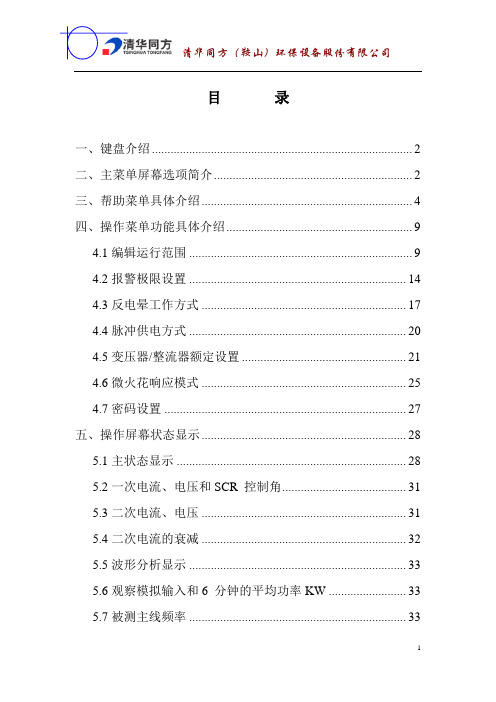
目录一、键盘介绍 (2)二、主菜单屏幕选项简介 (2)三、帮助菜单具体介绍 (4)四、操作菜单功能具体介绍 (9)4.1编辑运行范围 (9)4.2报警极限设置 (14)4.3反电晕工作方式 (17)4.4脉冲供电方式 (20)4.5变压器/整流器额定设置 (21)4.6微火花响应模式 (25)4.7密码设置 (27)五、操作屏幕状态显示 (28)5.1主状态显示 (28)5.2一次电流、电压和SCR 控制角 (31)5.3二次电流、电压 (31)5.4二次电流的衰减 (32)5.5波形分析显示 (33)5.6观察模拟输入和6 分钟的平均功率KW (33)5.7被测主线频率 (33)一、键盘介绍(0和1键为双重功能键)数字键——<0-9>数字键用以输入数据和选择菜单功能。
上、下箭头键——用来屏幕显示翻页左、右箭头键——输入数据时打空格<Enter/Hold>键——用来存储数据或者锁存显示<Menu>键——此键将回复到菜单设置状态1/RUN键——此键为绿色。
在输入数据时,它为数值1;在正常的ESP-S1操作中,当操作屏幕显示时,此键将启动ESP-S1的运行。
如ESP-S1已经处在工作状态,此键将重新启动斜率搜索。
HALT键——此键为红色。
在输入数据时,它为数值0;在正常ESP-S1操作中,当操作屏幕显示时,按下此键将会使火花消失,从而使ESP-S1操作停止,如ESP-S1已经处于报警停滞状态,按此键可消除报警。
<Enter-Hold>键——在输入数据时,此键用来储存输入的数据和设置。
在正常ESP-S1操作中,按此键将锁存主要状态显示《DISPLAY HOLD》30秒钟,以便于操作人员记录读数。
运行中按此键将不会影响控制系统的工作。
二、主菜单屏幕选项简介ESP-S1共有三个主菜单屏幕,操作人员可以获取所有的控制功能和帮助菜单。
在主菜单显示的情况下,按下相应的数字键即可进入不同的操作。
ESP-WROVER模组治具制作规范说明书

机台型号
ESP-WROOM-02
ESP-WROOM-02D
ESP-WROOM-02/02D-V1
ESP-WROOM-02DC
ESP-WROOM-02U
ESP-WROOM-02UC
Espressif
ESP-WROOM-02U-V3*
! /18
5
2019.01
2. 模组治具的主要结构
!
模组类型
V1.1
更更新表 2-1,增加新模组信息。
文文档变更更通知
用用户可通过乐鑫官网网订阅⻚页面面 https:///zh-hans/subscribe 订阅技术文文
档变更更的电子子邮件通知。
证书下载
用用户可通过乐鑫官网网证书下载⻚页面面 https:///zh-hans/certificates 下载产
Espressif
! /18
4
2019.01
2. 模组治具的主要结构
!
此串串口口板包括两颗串串口口芯片片,其在底箱的放置方方式如图 2-5 所示。根据夹具的类型放置对
应数目目的串串口口板(如“一一拖四”治具则需要放置 4 块串串口口板)。
!
图 2-6. 底板放置示意图
要求底板须固定在底箱里里里,防止止串串口口板位置不不固定导致管脚触碰短路路现象。固定时采用用螺
!
图 2-4. 活动台与模组台之间的距离示意
2.2. 底箱制作规范
2.2.1. 串串口口板
底箱内放有串串口口板,使用用的串串口口板的版本号为:ESP_Factory Test Board V1.3,如图 2-5
所示:
!
图 2-5. 串串口口板示意 (ESP_Factory Test Board V1.3)
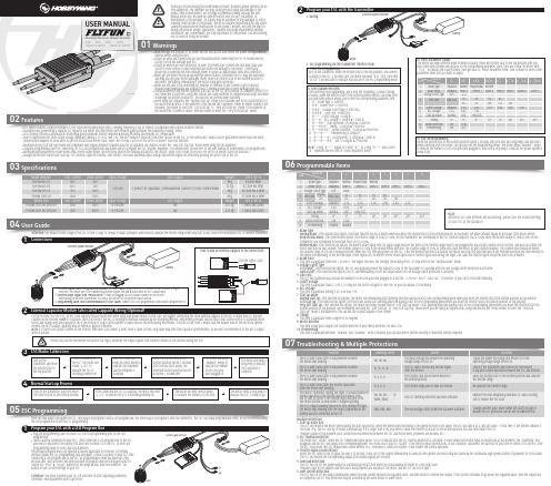
HOBBYWING ESC用户手册说明书
0103Specifications04User Guide05ESC Programming06Programmable Items07Troubleshooting & Multiple ProtectionsExternal Capacitor Module (also called Cappack) Wiring (Optional)2• DEO (Driving Efficiency Optimization) Technology greatly improves throttle response & driving efficiency and reduces ESC temperature.• Built-in high-power BEC with output voltage adjustable among 5.2V, 6.0V and 7.4V. The BEC module is separate from other circuits on the ESC, so the normal BEC output can be guaranteed (when issue like burntpower board happens) to allow users to get the aircraft back before crash. (Note: the FLYFUN 130A/160A HV OPTO V5 doesn’t have this function.)• Normal/Soft/Very Soft start-up modes are compatible with regular propeller airplanes and EDF jet airplanes (pls ensure to select the “Very Soft Start-up” mode when using EDF jet airplanes).• Separate programming cable for connecting ESC to a LED program box and allows users to program the ESC anytime, anywhere. (For detailed info, please refer to the user manual of HOBBYWING LED program box.)• Normal/proportional/reverse brake modes (esp. reverse brake mode) can effectively shorten the landing distance for the aircraft. (Note: the FLYFUN 130A/160A-HV-OPTO-V5 doesn’t have this function.)• Multiple protection features like start-up, ESC thermal, capacitor thermal, over-current, over-load, abnormal input voltage and throttle signal loss effectively prolong the service life of the ESC.There are two ways to program the ESC. One way is to program it with a LED program box; the other way is to program it with the transmitter. The ESC has many programmable items, so we recommend usingthe LED program box to do the ESC programming.For the FLYFUN 80A/120A-V5, its BEC load capacity may be insufficient when using high power servos. In that case, we suggest connecting the stock external cappack to the BEC’s output end (i.e. any idlechannel on the receiver *note 1) in parallel. Users can check if the BEC is working in overload condition by the following method: keep moving relevant throttle sticks (that control servos) to start/stop thoseservos and change directions quickly to see if the receiver or flight control system (if exists) will be restarted during the process. If restart occurs, then it means that the sudden load of the electronic systemexceeds the BEC’s output capability and an external cappack is needed.Note 1: if there is no vacant channel on the receiver, then users can connect a short, thick Y cable (as thin, long cable may affect the capacitor’s performance, so we don’t recommend it) to the BEC’s outputwires in parallel.40A · 60A · 80A · 120A130A HV OPTO · 160A HV OPTOUSER MANUALBrushless Electronic Speed Controller1. Brake TypeNormal Brake: After selected this option, the brake function will be activated when you move the throttle stick to the bottom position. In this mode, the brake amount equals to the brake force you’ve preset.Proportional Brake: After selected this option, the throttle range of 20% to 100% (on the transmitter) will correspond to the ESC throttle output of 0% to 100% while the throttle range of 20% to 0% (on thetransmitter) will correspond to the brake force of 0 to 100%.Reverse Brake: After selected this option, the Reverse Brake signal wire (its signal range must be the same as the throttle range) must to be plugged into any vacant channel on the receiver, and you can control themotor direction via that channel. The channel range of 0-50% is the default motor direction, the channel range of 50% to 100% will cause the motor to spin counterclockwise. The channel stick should be withinthe channel range of 0-50% (0 would be better) when the first time you power on the ESC. After the Reverse function is activated, the motor will stop first and then spin in the reversed direction and then increase tothe speed corresponding to the throttle input. Either signal loss, no matter reverse brake signal loss or throttle signal loss during the flight, can cause the throttle signal loss protection to be activated.2. Brake ForceThis item is adjustable from level 1 to level 7. The higher the level, the stronger the braking effect. It’s only effect in the “Normal brake” mode.3. Voltage Cutoff TypeSoft Cutoff: After selected this option, the ESC will gradually reduce the output to 50% of the full power in 3 seconds after the low-voltage cutoff protection is activated.Hard Cutoff: After selected this option, the ESC will immediately cut off the output when the low-voltage cutoff protection is activated.4. LiPo Cells:The ESC will automatically calculate the number of LiPo cells you have plugged in as per the “3.7V/Cell” rule if “Auto Calc.” is selected, or you can set this item manually.5. Cutoff VoltageThis item is adjustable from 2.8V to 3.8V (they are the cutoff voltages for one cell); or you can disable it if necessary.6. BEC VoltageThis item is adjustable among 5.2V, 6.0V and 7.4V.7. Start-up ModeNormal Start-up: After selected this option, the motor will immediately start spinning and then quickly reach to the corresponding speed when you move the throttle stick from bottom position to top position.Soft Start-up: After selected this option, the motor will slowly start spinning and then quickly reach to the corresponding speed when you move the throttle stick from bottom position to top position.Very Soft Start-up: After selected this option, the motor will slowly (slower than in “Soft Start-up Mode”) start spinning and then quickly reach to the corresponding speed when you move the throttle stick frombottom position to top position. We recommend selecting the “Soft Start-up” or “Very Soft Start-up” mode when you are flying an airplane with a big-sized ducted fan. Please ensure to select the “Very SoftStart-up” mode if the diameter of the ducted fan on your airplane is over 90mm.8. TimingThis item is adjustable from 0 degree to 30 degrees.9. Motor RotationThis item allows you to adjust the rotation direction of your motor between CW and CCW.10. FreewheelingThis item is adjustable between “Enabled” and “Disabled”. With it enabled, you can have better throttle linearity or smoother throttle response.Multiple Protections1. Start-up Protection:The ESC will monitor the motor speed during the start-up process. When the speed stops increasing or the speed increase is not stable, the ESC will take it as a start-up failure. At that time, if the throttle amount isless than 15%, the ESC will try to restart automatically; if it is larger than 20%, you need to move the throttle stick back to the bottom position first and then restart the ESC.(Possible causes of this problem: poor connection/ disconnection between the ESC and motor wires, propellers are blocked, etc.)2. ESC Thermal Protection:The motor will “stutter” when the ESC temperature goes above 110℃ to indicate that the ESC thermal protection is activated. If lower down the throttle input to below 60% at this moment, the “stuttering” willdisappear and the ESC will output the corresponding power. The motor will re-start to “stutter” if the throttle input exceeds 60%. In this condition, disconnect the battery first and then re-connect it to the ESC afterthe ESC cools down (the ESC temperature cannot exceed 70℃, otherwise it cannot be started), it will resume the normal operation.3. Throttle Signal Loss Protection:When the ESC detects loss of signal for over 0.25 second, it will cut off the output immediately to avoid an even greater loss which may be caused by the continuous high-speed rotation of propellers or rotor blades.The ESC will resume the corresponding output after normal signals are received.4. Overload Protection:The ESC will cut off the power/output or automatically restart itself when the load suddenly increases to a very high value.(Possible cause to the sudden load increase is that propellers are blocked or the motor and the ESC are out of sync.)5. Over-current Protection:The ESC will cut off the output immediately when the peak current exceeds the regulated value, and then restart to resume the output. If the current continues to go above the regulated value, then the output willbe completely cut off. This protection may be activated by the burnt motor or some others.Note:different ESCs have different default settings, please take the default settingsof each ESC as the standard.)01故障描述电调通电以后不工作,鸣叫报警提示音“哔哔,哔哔,哔哔,哔哔,…...”说明输入的电压不在电调的工作电压之内。
esp-07wifi规格书

ESP-07 WiFi 模块规格书版本2015年8月23日免责申明和版权公告本文中的信息,包括供参考的URL地址,如有变更,恕不另行通知。
文档“按现状”提供,不负任何担保责任,包括对适销性、适用于特定用途或非侵权性的任何担保,和任何提案、规格或样品在他处提到的任何担保。
本文档不负任何责任,包括使用本文档内信息产生的侵犯任何专利权行为的责任。
本文档在此未以禁止反言或其他方式授予任何知识产权使许可,不管是明示许可还是暗示许可。
Wi-Fi 联盟成员标志归 Wi-Fi 联盟所有。
文中提到的所有商标名称、商标和注册商标均属其各自所有者的财产,特此声明。
注意由于产品版本升级或其他原因,本手册内容有可能变更。
深圳市安信可科技有限公司保留在没有任何通知或者提示的情况下对本手册的内容进行修改的权利。
本手册仅作为使用指导,深圳市安信可科技有限公司尽全力在本手册中提供准确的信息,但是深圳市安信可科技有限公司并不确保手册内容完全没有错误,本手册中的所有陈述、信息和建议也不构成任何明示或暗示的担保。
目录1. 产品概述 (2). 特点 (2). 主要参数 (3)2. 接口定义 (4)3. 外型与尺寸 (6)4. 功能描述 (6). MCU (6). 存储描述 (7). 晶振 (7). 接口说明 (7). 最大额定值 (8). 建议工作环境 (8). 数字端口特征 (9)5. RF 参数 (9)6. 功耗 (10)7. 倾斜升温 (11)8. 原理图 (12)9. 产品试用 (12)1.产品概述ESP-07 WiFi 模块是由安信可科技开发的,该模块核心处理器 ESP8266 在较小尺寸封装中集成了业界领先的 Tensilica L106 超低功耗 32 位微型 MCU,带有 16 位精简模式,主频支持 80 MHz 和 160 MHz,支持 RTOS,集成 Wi-Fi MAC/ BB/RF/PA/LNA,板载天线。
该模块支持标准的 b/g/n 协议,完整的 TCP/IP 协议栈。
ESP用户手册

ESP培训手册编制:徐峰目录1.软件安装与快速启动向导 (2)这里以阅读器MINI作为介绍对象 (2)1.1S TEP1------检查硬件设备 (2)1.2S TEP2------连接系统 (2)1.3S TEP3------阅读器安装位置 (3)1.4S TEP4------安装ESP软件 (3)ESP是M ICROSCAN为所有阅读器安装程序与测试程序软件,并不是说它是一种接到指令立即执行的工具。
ESP 软件的目的是提供快速,简捷的方式建立和设定你的阅读器参数。
当你的阅读器连接上主机时,你就可以用ESP软件进行设定和阅读的控制。
(3)从M ICROSCAN CD安装ESP软件 (3)1.5S TEP5------阅读器模式选择 (4)1.6S TEP6------自动连接模式 (5)1.7S TEP7------标记的定位 (6)1.8S TEP8------校验参数的设置 (8)1.9S TEP9------阅读速率测试 (8)1.10S TEP10------用ESP软件设定阅读器的参数 (9)1.11S TEP11------用ESP软件对菜单进行修改与保存 (10)2,ESP软件的使用 (11)2.1启动ESP程序 (11)2.2连接硬件 (11)2.3阅读参数设定 (12)2.3.1通讯 (12)2.3.3条码类型设置 (14)2.3.5条码质量的设置 (15)2.4摄像参数设置 (16)2.5发送/保存命令 (19)2.5终端测试 (20)2.6自动连接 (20)2.7阅读器的模式转换 (20)1.软件安装与快速启动向导这里以阅读器MINI作为介绍对象1.1Step1------检查硬件设备警告:在给系统供电前必须保证各硬件已正确连接,总是保持未连接任何硬件时系统处于无电状态1.2 Step2------连接系统连接时采用串口RS-232协议1.3 Step3------阅读器安装位置阅读器安装位置的焦距大约在50mm~~150mm之间。
净化器说明书

非常感谢您使用我们的产品。您已拥有一台高品质的空气净化器,且有一年的产品保修期。您的满意 对我们来说意味着一切,我们期待着永远为您服务。为了确保您正确使用本台机器,请在使用前仔细阅读 此【说明书】,并与【保修卡】一起妥善保管。
目录
一、产品简介 二、产品优势 三、安全说明及注意事项
六、ESP清洗和产品维护
使用本产品后不久,就会给您室内的环境送出干净新鲜的空气,为了保证本产品净化工 作正常,请在使用2-3个月后,清洗一次ESP集尘网,使用6-8个月以后,更换一次活性碳过 滤网。
内部的ESP静电集尘网是整个产品的一个重要部分,所以清洗时,请参照ESP静电集尘网 部分。
清洗ESP静电集尘网和初效过滤网及更换活性碳过滤网。 ※ 清洗ESP静电集尘网:
1.低档 2.中档 3.高档 产品的具体操作要求 1 待机;插上电源,首先3个LED亮(红色) 处于准备工作状态; 2 按下开机按键;3个LED红色指示灯变为蓝色,同时机子启动默认为最高档,同时高档指 示灯亮 备注:无论何时重新启动机器,都默认为最高档; 3 再按;转到中档,中档的指示灯亮,同时高档的指示灯灭; 4 再按;转到低档,低档的指示灯亮,同时中档的指示灯灭; 5 再按;待机,低档的指示灯灭,3个LED蓝色变为红色; 6 拔掉电源,所有灯灭,关机。
二、产品优势:
您的空气净化器有以下众多优势: ●超长、超大空间ESP可清洗式静电集尘过滤器,永久使用清洁方便 ●强劲高压,杀菌消毒 ●负离子活性氧消烟除臭 ●无臭氧产生,环保节能 ●整机能耗低,能效率比高达1:9以上 ●产品具要低风阻、低噪音 ●高度集成智能化 ●一键智能操作,使用简便。
三、安全说明及注意事项
ESP8089_WiFi 数据手册 中文

ESP8089 802.11bgn 芯片组
7
7.1
规格
功耗
下列功耗数据是基于 3.3V 的电源、25C 的周围温度,并使用内部稳压器测得。 [1] 所有测量均在没有 SAW 滤波器的情况下,于天线接口处完成。 [2] 所有发射数据是基于 90% 的占空比,在持续发射的模式下测得的。
模式 传送 802.11b, CCK 1Mbps, POUT=+19.5dBm 传送 802.11b, CCK 11Mbps, POUT=+18.5dBm 传送 802.11g, OFDM 54Mbps, POUT =+16dBm 传送 802.11n, MCS7, POUT =+14dBm 接收 802.11b, 包长 1024 字节, -80dBm 接收 802.11g, 包长 1024 字节, -70dBm 接收 802.11n, 包长 1024 字节, -65dBm 系统待机模式 深度睡眠 节能模式 DTIM 1 节能模式 DTIM 3 关机 最小值 通常 215 197 145 135 60 60 62 0.9 10 1.2 0.86 0.5 最大值 单位 mA mA mA mA mA mA mA mA uA mA mA uA
9|Page
乐鑫信息科技
2013 年 9 月 28 日
ESP8089 802.11bgn 芯片组
6
ESP8089 的应用主体
手机 便携式媒体播放器(PMP),如 MP3 或 MP4 播放器 移动游戏机 数码相机 摄像机 平板电脑
10 | P a g e
乐鑫信息科技
2013 年 9 月 28 日
7|Page
乐鑫信息科技
2013 年 9 月 28 日
ESP210气体探测器说明书 (1.4)
3.1 开/关机
ESP210使用说明书
开机 关机状态下,按住 键,显示屏下方出现3秒倒计时。3秒后,探测器开机,依次 对蜂鸣器、LED指示灯以及显示屏进行检查,然后进入传感器预热状态。如无任何提 示,请检查电池是否有电。 开机时,如果电池电量严重不足,将导致无法开机,这时请插入随机配备的充电 器,充满电后使用。
邮箱:sale@
深圳市特安电子有限公司
Shenzhen ExSaf Electronics Co., Ltd.
质量方针
通过我们对工作质量的持续改 进来满足顾客的需求,并使顾客得 到发展及成功。
安全事项
设备使用和维护之前务必仔细阅读本说明书。 特别留意警告和注意事项。 所有警告都在此处列出,并在说明书相应章节中重复提到。注意事项分别在相应章 节中列出。
2. 产品技术指标 ………………………………………………… 3 2.1 技术指标 ………………………………………………… 3 2.2 产品安全和认证 ………………………………………… 3
3. 产品使用 ……………………………………………………… 4 3.1 开关机 …………………………………………………… 5 3.2 测量 ……………………………………………………… 6 3.3 报警 ……………………………………………………… 7 3.4 故障 ……………………………………………………… 9 3.5 信息提示 ………………………………………………… 10
警告
安装过程及使用必须严格遵照国家相关标准要求。
只能由合格人员使用和维护此设备。使用和维护前必需完全阅读和理解用户手册的内容。 对探测器内部的任何操作都必须由专业人员执行。
ESP32 ESP-SR 用户手册说明书

ESP32ESP-SR用户手册Release master乐鑫信息科技2023年10月24日Table of contentsTable of contents i 1入门指南31.1概述 (3)1.2准备工作 (3)1.2.1必备硬件 (3)1.2.2必备软件 (3)1.3编译运行一个示例 (3)2AFE声学前端52.1AFE声学前端算法框架 (5)2.1.1概述 (5)2.1.2使用场景 (5)2.1.3选择AFE Handle (8)2.1.4输入音频 (8)2.1.5输出音频 (9)2.1.6使能唤醒词识别WakeNet (9)2.1.7使能回声消除算法AEC (9)2.1.8资源消耗 (9)2.2乐鑫麦克风设计指南 (10)2.2.1麦克风电器性能推荐 (10)2.2.2麦克风结构设计建议 (10)2.2.3麦克阵列设计建议 (10)2.2.4麦克风结构密封性建议 (10)2.2.5回声参考信号设计建议 (11)2.2.6麦克风阵列一致性验证 (11)3唤醒词133.1WakeNet唤醒词模型 (13)3.1.1概述 (13)3.1.2WakeNet的使用 (14)3.1.3资源消耗 (15)3.2乐鑫语音唤醒方案客户定制流程 (15)3.2.1唤醒词定制服务 (15)3.2.2硬件设计与测试服务 (16)4命令词174.1MultiNet命令词识别模型 (17)4.2命令词识别原理 (17)4.3命令词格式要求 (18)4.4自定义命令词方法 (18)4.4.1MultiNet6定义方法: (18)4.4.2MultiNet5定义方法: (18)4.4.3通过调用API修改 (19)4.5MultiNet的使用 (20)4.5.1MultiNet初始化 (20)4.5.2MultiNet运行 (21)4.5.3MultiNet识别结果 (21)4.6资源消耗 (21)5TTS语音合成模型235.1简介 (23)5.2简单示例 (23)5.3编程指南 (24)5.4资源消耗 (24)6模型加载256.1配置方法 (25)6.1.1使用AFE (25)6.1.2使用WakeNet (25)6.1.3使用MultiNet (26)6.2模型使用 (26)6.2.1模型数据存储在Flash SPIFFS (27)7性能测试结果297.1AFE (29)7.1.1资源消耗 (29)7.2WakeNet (29)7.2.1资源消耗 (29)7.2.2性能测试 (29)7.3MultiNet (30)7.3.1资源消耗 (30)7.3.2Word Error Rate性能测试 (30)7.3.3Speech Commands性能测试(空调控制场景) (30)7.4TTS (30)7.4.1资源消耗 (30)7.4.2性能测试 (30)8测试方法与测试报告318.1测试场景要求 (31)8.2测试案例设计 (31)8.3乐鑫测试与结果 (32)8.3.1唤醒率测试 (33)8.3.2语音识别率测试 (33)8.3.3误唤醒率测试 (33)8.3.4唤醒打断率测试 (33)8.3.5响应时间测试 (34)9术语表359.1通用术语 (35)9.2特别术语 (35)本文档仅包含针对ESP32芯片的ESP-SR使用。
esp8266-01wifi模块用户手册

ESP8266 WiFi模块用户手册目录术语和缩写 ....................................................... 错误!未定义书签。
1. 产品简介 ......................................................... 错误!未定义书签。
. 概述 ......................................................... 错误!未定义书签。
产品特性 ................................................. 错误!未定义书签。
模块封装 ................................................. 错误!未定义书签。
模块基本参数 ............................................. 错误!未定义书签。
. 硬件介绍 ..................................................... 错误!未定义书签。
. 功耗 ......................................................... 错误!未定义书签。
. 射频指标 ..................................................... 错误!未定义书签。
. 尺寸 ......................................................... 错误!未定义书签。
. WiFi 天线 .................................................... 错误!未定义书签。
. 推荐炉温曲线 ................................................. 错误!未定义书签。
新EPS操作维护手册..

EPS操作维护手册目录第一章概述 (1)1.1 ZYJ系列EPS应急电源技术特点: (1)1.2外形尺寸 (1)1.3主要技术参数 (1)1.4工作环境 (2)1.5 储存环境 (2)第二章工作原理 (3)2.1工作原理 (3)2.2 保护功能 (3)第三章安装运行 (5)3.1 容量配置 (5)3.2 安装位置 (5)3.3 安装接线 (5)3.4 前面板操作和显示示意图及说明 (6)3.5 EPS应急电源试运行 (10)3.6 EPS应急电源的正常启动、关闭操作步骤 (10)第四章显示异常信息和报警信号 (11)4.1 常见故障的原因及处理方法 (11)第五章维护保养和售后服务 (12)5.1 维护保养 (12)5.2 蓄电池组的维护 (12)第一章概述ZYJ系列EPS应急电源,体现了当今世界最先进的电力电子技术,是一种功能齐备、性能卓越的应急电源,具有高效率、高可靠度、高智能的优点。
1.1 ZYJ系列EPS应急电源技术特点:●应急单元采用微处理器控制的SPWM技术,纯正弦波输出,波形纯净●独有的动态电流环控制技术确保逆变器可靠运行●负载适应能力强,包括电容性、电感性、混合性负载●过载能力和抗冲击能力强●具有输入过、欠压,输出过、欠压,过温,过载等完善的保护功能●逆变器前面板有LCD、LED双重显示方式,状态一目了然●效率高(非应急供电时,基本不耗电)、噪音低、无排烟、无火载隐患●自动切换,可实现无人值守●性能稳定,安全可靠,使用寿命长1.2外形尺寸标准机柜外形尺寸表1.3 主要技术参数ZYJ系列应急电源主要技术参数(以ZYJ100KS-480为例)1.4 工作环境本产品的使用环境请尽量满足以下要求:●置于无尘垢和干燥通风的场所 (在宽敞的房间内安装本产品,房间内安装强制性通风设备) ●适当的温度 (EPS应急电源能在-10℃~40℃的室内环境下运行,但进行开启时的温度最好高于0℃,理想的操作温度为10℃~25℃)●相对湿度符合要求(10%~90%)不结露●海拔≤1000m 海拔高度超过1000米时,建议降低机器额定容量使用(参照GB3859.2)●无水蒸汽或其它腐蚀性气体,附近无易燃易爆品●有符合安全规定的前级电源1.5 储存环境本产品在存放时应注意以下事项,以避免可能遭受的不良影响。
EPS说明书
第一章序言1.1 概述随着社会的信息化、现代化发展,对供电的可靠性要求越来越高,大型建筑,如机场、车站、会展中心、体育馆、政府机构办公楼及高层建筑等,一旦供电系统突然发生故障而中断供电,将会给社会正常的生活秩序造成破坏,造成重大的政治影响或经济损失。
然而电力故障突发性强,往往不以人们的意志为转移,因为无论供电部门管理得再严格,电网设施再先进,断电也在所难免。
按《供配电系统设计规范》的规定,电力负荷根据其重要性和中断供电在政治、经济上造成的损失和影响程度,分为一、二、三级负荷;对于一级负荷应由两个电源供电,当一个电源发生故障时,另一个电源应不致同时受到损坏,一级负荷中特别重要负荷,除上述两个电源外,还必须增设应急电源;对于二级负荷,宜采用两回线路供电。
ZHEPS系列EPS应急电源是本公司集多年的电力电子与监控设备的运行与设计经验,采用最新的高频开关整流技术、SPWM高频逆变技术、电池监测和微机监控技术开发的高可靠和高性能的新一代电源产品,该产品为一、二级负荷和特别重要负荷用电设备或消防设备提供第二或第三电源,已广泛应用于各类建筑、铁道交通、机场等领域。
1.2 注意事项本使用手册提供给用户安装调试、操作使用及故障诊断等有关注意事项,务请妥善保管,并请您在使用本产品前仔细阅读本使用手册。
◆在仔细阅读理解本说明手册并能正确使用之前,请不要安装、操作、维护或检查本产品。
◆遵从产品及附带的印刷品中标示的警告事项及说明。
◆接线前必须先断开前级电源。
◆ EPS电源必须可靠接地,接地电缆尽量使用粗线,连接地点尽量靠近EPS电源,接地线尽量短。
◆ EPS电源在切断输入电源后,内部仍会有高压,切勿打开机箱触摸内部器件,以免对操作者和本产品造成伤害。
◆安装地点请远离水、蒸气和其它液体物质,远离易燃易爆物质。
◆安装的电缆必须符合要求,请不要使用电缆线超载工作,避免火灾及电击事故发生。
1.3 开箱检查ZHEPS系列应急电源在出厂前已经经过严格的检验,但在运输途中可能受损,因此,开箱后请先检查下列各项是否齐全,确认型号、容量、输入电压、输出电压等是否与订购时所指定的内容相符;如果出现异常或内容不符,请尽快与经销商联系。
ESP32蓝牙配网用户指南说明书

1. 简介
!
简介
1.
1.1. 概述
作为集成 2.4 GHz Wi-Fi 和蓝牙牙双模的单芯片片方方案,ESP32 支支持 SmartConfig 和蓝牙牙配网网
两种模式,用用户可以使用用 ESP32 为物联网网设备进行行行安全配网网。
蓝牙牙在设备配置方方面面有以下优势:
•
蓝牙牙协议公开并且容易易扩展。
•
通过蓝牙牙可以便便捷地搜索到附近的蓝牙牙设备。
•
蓝牙牙协议安全性高高,用用户通过蓝牙牙连接给设备授权后,才把密码传输到设备端。
•
在路路由无无法正常工工作的情况下,客户还能通过蓝牙牙把数据传输给手手机,通过手手机把
数据上传到网网络。
•
在 Wi-Fi 出现问题的时候,手手机也能连接蓝牙牙设备,通过发送指令控制设备。
2.2. ESP32 端开发
在 ESP32 端的代码中,密钥协商等安全处理理的流程,由使用用者来决定和开发。手手机 app
向 ESP32 发送 negotiate data,negotiate data 类型的包将传送给应用用层处理理。如果应用用
层不不愿意处理理,可使用用 BluFi 提供的 DH 加密算法来磋商密钥。应用用层需向 BluFi 注册表
品证书。
目目录
1. 简介 ......................................................................................................................................... 1
3. ESP32 蓝牙牙配网网示例例 ..............................................................................................................5
