RTL8101L Power consumption
笔记本常见的芯片 (修改)

红色:代表我见过的紫色:代表我见过加上去的千兆网卡芯片:88E8001、RTL8101L笔记本电脑温度传感器芯片:ADM1032、DS1620、LM26、1、LM 75 76 78 79 LM 75负责CPU温度LM 75负责电压CPU风扇转速及主板温度。
2、S:S5597/5595,内速温控功能。
3、WINBOLD 系列:83781B 温度监控芯片83782B 温度监控芯片83783B 温度监控芯片支持6MA33/66芯片笔记本电脑指纹传感器: AES2501A\笔记本电脑液晶显示器高压驱动芯片:BA9741F、BD9766FV、BD9882F、BD9883FV、MAX1522/MAX1523/MAX1524 、OZ960、L1451、TL5001、笔记本电源管理芯片:(可待换)RT9221---SC1164RT9222---SC1165RT9223---SC1153RT9224---HIP6004BRT9224B---CL6911ERT9224C---HIP6004DRT9227A---HIP6016RT9228---HIP6018BRTL9229---HIP6019BRT9230---HIP6020RT9231---HIP6021RT-9231A---HIP6021ART9238---ISL6524RT9239---HIP6021笔记本待机控制芯片:max1631 TB62501 PMH4 H8笔记本电脑开机控制芯片:BD4175KV、BD4176KVT、IPC47N253、PC87551、TB62506、PC8394T(T43)笔记本电脑I/O芯片:FDC37N97、IT8716FCX、IT8705F 、IT8712F 、IT8712G 、IT8702 、W83627HF 、W8671F 、笔记本电脑CPU散热风扇转速控制芯片:G781、笔记本电脑主板时钟芯片:ICS950810、ICS954302、ICS954310、ICS954309、SLG84420、笔记本电脑系统供电控制芯片:LTC1628、LTC3728L 、MAx1632、MAx1901、MAX1977、MAx8734、SC1403、SC1404、SC2450、SI786LG、笔记本电脑内存供电控制芯片:ISL6224 、ISL6225 、ISL6227、ISL6537、G2996、MAx1540、MAxl541、MAx1623、MAX1644、MAx1809、MAx1844、MAX1992/MAX1993、MAX1858、MAX8505、MAX8632、MAx8743、MAx8794、SC470、SC1485、SC1486/SC1486A 、TPS51117、TPS51124、TPS54610、TPS54672、笔记本电脑CPU供电控制芯片:ADP3181 、ADP3203 ADP3205、ADP3421 、APW7057、IPM6220A 、ISL6217、ISL6223、ISL6262、LTC3716、LTC3735、LTC1709 、MAX1830/MAX1831 、MAx1907、MAx1987、MAx8760、MAx8770、SC1474、SC1476、SC451、SC452、CPU供电芯片:ADP3166、ADP3170、ADP3180、ADP3181、ADP3203、ADO3205、ADP3207、ADP3208、ADP3209、ADP3421、AIC1567ISL6215、ISL6217、ISL6218、ISL6219、ISL6223、ISL6227、ISL6260、ISL6262、LTC1436、LTC1736、LTC1709、LTC3716、LTC3735、MAX1532、MAX1533、MAX1710、MAX1711、MAX1712、MAX1714、MAX1717、MAX1718、MAX1830、MAXl831、MAX1897、MAX1907、MAX1987、MAX1988、MAX798、MAX8760、MAX8770、MAX8771、MAX8774、SC451、SC452、SC1474、SC1476、笔记本电脑充电控制芯片:AAT3680 、BQ24700 、BQ24701 、BQ24702/BQ24703 、DS2770 、LT1505、LTC4008 、MAX1645B 、MAX1736 、MAX745、MAX1873 、MAx8724、MAx8725、MAx8765、MB3887、MB39A126PFV、TL594、TPC8109 东芝 120000 0.9 SOP-8笔记本电池电量检测芯片:BQ2040、BQ2060低压差稳压器:AAT3200、AME8824、AMS1505、AP15912、G9338、LPL1084、MAX8863、MIC5205 、SCl565、SC4215、SI9183、100mA低压差稳压器:LP2951、笔记本主板声卡芯片: ALC200 、ALC201A 、ALC262、ALC655(我的废旧主板) 、ALC658、 ALC660、 ALC86l、ALC880、 ALC883、ALC202、AD1986、CS4205、CS20468、CS20549、Esl92l、PT2353、笔记本主板音频功率放大芯片: AN12943、APA2020/TPA0202、G1420、LM4835、LM4838、LM4882、LM4861 、LM4863、LM4880/LM4881 、LM4911 、MAX9710、MAx9750、MAx9751、MAX9755、MAx9789、MAx9790、TPA0142、TPA0142、TPA0312、TPA6017、音频功放芯片:APA2020、TPA0142、TPA0312、TPA6017、TPA0202、LM4835、LM4838、LM4861、LM4863、LM4880、LM4881、LM4882、LM4911、MAX9710、MAX9750、MAX9751、MAX9755、MAX9789、MAX9790、ESS1980S、8552TS、8542TS、TPA0302、AU8810 、BA7786、AN1294、AN12941、AN12942B、AN12943 G1420、主板声卡芯片: ALC655(我的废旧主板)主板网卡芯片:RTL8201CL主板io芯片:Fintek f71872fCMOS 控制芯片:GD75232主板电源管理芯片:SC6243主板内存供电芯片:AP1250、APW7060 、CM8501/CM8501A 、CM8562 、ISL6520 、NCP5201 、RT9202、RT9214、APW7120、RT9203 、RT9173、RT9218、SC2595、SC2614、SC411、SC2616、主板CPU供电控制芯片:ADP3166 、ADP3170 、ADP3180 、ADP3198、AIC1567 、CS5322 、FAN5019、FAN5090、FAN5056 、HIP6004 、HIP6016 、HIP6017 、HIP6018 、HIP6019 、HIP6020 、HIP6021 、HIP6302 、HIP6301、HIP6521 、ISL6312 、ISL6524 、I ISL6556 、SL6559、ISL6561 、ISL6566、L6711、L6917、NCP5314 、TL494/KA7500/MB3759 、L6714 、LM2637/LM2638 、RC5051、RT8802A、RT9237 、RT9238、RT9246A、RT9241 、RT9243 、RT9245 、RT9248 、SC2643(我的废旧主板)、SC1121S SC1155、SC1189 、SC2422、主板时钟芯片:CS950502、CY28405—2/ICS952606、CY28404C、ICS9248?153、ICS954218、ICS9248?151、ICS9248?39、ICS950202、ICS950208BF、ICS950901、ICS950902 、ICS950908 、ICS952018 、ICS952617 、ICS952643 、ICS954127 、双运算放大器:LM13700M、满摆幅输入/输出运算放大器:MAX4490、四电压比较器:LM324、双路可编程电流LJSB开关:MAx1558、主板供电控制芯片:MAx1626、MAxl627、多通道RS-232线性驱动/接收器:MAX3243 3~5V、主板开机芯片:MS-6、笔记本电脑键盘/电源控制芯片:Pc87570、笔记本电脑I/O控制芯片:PC87591、PC97551、高速差分开关芯片: P131500E、MAX4927\双路电压控制开关:SC338、RS-232接口驱动/接收芯片:ST75185、具有串行接口的1A双插槽PC卡电源开关:TPS2206、TPS2211、主板声卡芯片:CMI9738 、VT1611A、VT1612A、AD1885、AD1888、AD1981、端口限流保护芯片:AAT4280、MIC2545、笔记本电脑供电控制芯片:ADP3168、笔记本电脑电池充/放电控制芯片:ADP3806、笔记本电脑电池电量检测芯片:BQ2040、BQ2060、M61040FP、笔记本电脑电源适配器控制芯片:FAN7601、M51995A、NCP1205、NCP1207、88E8001千兆网卡芯片AD1986主板声卡芯片ADM1032笔记本电脑温度传感器芯片ADP3198主板CPU供电控制芯片ADP3205笔记本电脑CPU供电控制芯片ADP3207笔记本电脑CPU供电控制芯片ADP3806笔记本电脑电池充、放电控制芯片(IBM T43)AES2501A笔记本电脑指纹传感器ALC202主板声卡芯片ALC262笔主板声卡芯片ALC658主板声卡芯片ALC660主板声卡芯片ALC86l主板声卡芯片ALC880主板声卡芯片ALC883主板声卡芯片AME8824低压差稳压器AN12943音频功率放大芯片AP1250主板内存供电芯片AP15912大电流低压差稳压器APW7057笔记本电脑芯片组供电控制芯片BA9741F笔记本电脑液晶显示器高压驱动芯片BD4175KV笔记本电脑开机控制芯片BD9766FV笔记本电脑液晶显示器高压驱动芯片BD9882F笔记本电脑液晶显示器高压驱动芯片BD9883FV笔记本电脑液晶显示器高压驱动芯片CS4205笔记本电脑声卡芯片CS20468笔记本电脑声卡芯片CS20549笔记本电脑声卡芯片CY28405—2/ICS952606主板时钟芯片Esl92l笔记本电脑声卡芯片FAN5019主板CPU供电控制芯片FAN5090主板CPU供电控制芯片FDC37N972笔记本电脑I/O芯片G1420笔记本电脑音频功放芯片G2996笔记本电脑内存供电控制芯片G781笔记本电脑CPU散热风扇转速控制芯片G9338低压差线性稳压控制器ICS950810笔记本电脑主板时钟芯片ICS954302笔记本电脑主板时钟芯片ICS954309笔记本电脑主板时钟芯片ICS954310笔记本电脑主板时钟芯片ISL6227笔记本电脑内存供电控制芯片ISL6262笔记本电脑CPU供电控制芯片ISL6559主板CPU供电控制芯片ISL6566主板CPU供电控制芯片IT8716FCX主板I/O芯片LPL1084低压差稳压器L6711主板CPU供电控制芯片L6917主板CPU供电控制芯片LM13700M双运算放大器LM26笔记本电脑温度传感器LM324四电压比较器LM4835/LM4838笔记本电脑音频功放芯片LM4882笔记本电脑音频功放芯片LP2951 100mA低压差稳压器IPC47N253笔记本电脑开机芯片LTC3716笔记本电脑CPU供电控制芯片LTC3735笔记本电脑cPu供电控制电路MAx1540/MAxl541笔记本电脑内存/芯片组供电控制芯片MAx1558双路可编程电流LJSB开关MAx1623笔记本电脑内存供电电路MAx1626/MAxl627主板供电控制芯片MAx1632笔记本电脑系统供电控制芯片MAx1809笔记本电脑内存供电电路MAx1844笔记本电脑芯片组/显卡供电控制芯片MAx1901笔记本电脑系统供电控制芯片MAx1907笔记本电脑cPu供电控制芯片MAx1987笔记本电脑cPu供电控制芯片MAX3243 3~5V多通道RS-232线性驱动/接收器MAX4490满摆幅输入/输出运算放大器MAX8505笔记本电脑芯片组控制芯片MAX8632笔记本电脑内存供电控制芯片MAx8724笔记本电脑充电控制芯片MAx8725笔记本电脑充电控制芯片MAx8734笔记本电脑系统供电控制芯片MAx8743笔记本电脑显卡/芯片组供电控制芯片MAx8760笔记本电脑cPu供电控制芯片MAx8765笔记本电脑电池充电控制芯片MAx8770笔记本电脑CPU供电控制芯片MAx8794笔记本电脑DDR内存供电控制芯片MAX8863低压差稳压芯片MAX9710笔记本电脑音频功放芯片MAx9750/MAx9751/MAX9755笔记本电脑音频功放芯片MAx9789/MAx9790笔记本电脑音频功放芯片MB3887笔记本电脑充电控制电路MlB39A126PFV笔记本电脑充电控制芯片MS-6主板开机芯片PC87551笔记本电脑控制芯片Pc87570笔记本电脑键盘/电源控制芯片PC87591笔记本电脑I/O控制芯片PC97551笔记本电脑I/O控制芯片P131500E/MAX4927高速差分开关芯片PT2353笔记本电脑音效处理芯片RT8802A主板CPu供电控制芯片RT9202主板DDR内存供电控制芯片RT9214/APW7120芯片组/内存供电控制芯片RT9218芯片组/内存供电控制芯片RT9238主板CPU供电控制芯片RT9246A主板CPU供电控制芯片RTL8101L主板网卡芯片RTL8201CL 主板网卡芯片SC1403笔记本电脑主电源控制芯片SC1404笔记本电脑主电源控制芯片SC1474笔记本电脑芯片组供电控制芯片SC1476笔记本电脑芯片组供电控制芯片SC1485笔记本电脑芯片组供电控制芯片SCl565低压差稳压器SC2450笔记本电脑主电源控制芯片SC2595主板DDR内存供电控制芯片SC2614主板DDR内存供电控制芯片SC2643主板CPU供电控制芯片SC338双路电压控制开关SC411主板芯片组供电控制芯片SC4215具有使能功能的低压差稳压器SC451笔记本电脑CPU供电控制芯片SC452笔记本电脑CPU供电控制芯片SC470笔记本电脑显卡供电控制芯片SI786LG笔记本电脑供电控制芯片SI9183低压差稳压器SLG84420笔记本电脑主板时钟芯片ST75185 RS-232接口驱动/接收芯片TB62506笔记本电脑开机控制芯片TL1451笔记本电脑液晶屏高压驱动控制芯片TL5001笔记本电脑液晶屏高压驱动控制芯片TL594-笔记本电脑充电控制芯片TPA0142笔记本电脑音频功放芯片TPA0312笔记本电脑音频功放芯片TPA6017笔记本电脑音频功放芯片TPC8010(T43)TPS2206具有串行接口的1A双插槽PC卡电源开关TPS2211具有并行接口的1A单槽位PC卡电源开关TPS51117笔记本电脑供电控制芯片TPS51124笔记本电脑芯片组供电控制芯片TPS51120笔记本电源管理芯片TPS54610笔记本电脑内存供电控制芯片VT1611A主板声卡芯片VT1612A主板声卡芯片AAT3200 低压差稳压器AAT3680 笔记本电脑充电控制芯片AAT4280 端口限流保护芯片AD1885 主板声卡芯片AD1888 主板声卡芯片AD1981 主板声卡芯片ADP3160/ADP3167 笔记本电脑供电控制芯片ADP3166 主板CPU供电控制芯片ADP3168 笔记本电脑供电控制芯片ADP3170 主板CPU供电控制芯片ADP3180 主板CPU供电控制芯片ADP3181 笔记本电脑CPU供电芯片ADP3203 笔记本电脑CPU供电芯片ADP3421 笔记本电脑CPU供电芯片ADP3806 笔记本电脑电池充/放电控制芯片AIC1567 主板CPU供电控制芯片ALC200 主板声卡芯片ALC201A 主板声卡芯片ALC655 主板声卡芯片AMS1505 低压差稳压器APA2020/TPA0202 小功率音频功率放大芯片APW7060 主板供电控制芯片BQ2040 笔记本电脑电池电量检测芯片BQ2060 笔记本电脑电池电量检测芯片BQ24700 笔记本电脑充电控制芯片BQ24701 笔记本电脑充电控制芯片BQ24702/BQ24703 笔记本电脑充电控制芯片CM8501/CM8501A 主板内存供电控制芯片CM8562 主板内存供电控制芯片CMI9738 主板声卡芯片CS5322 主板CPU供电控制芯片CS950502 主板时钟芯片CY28404C 主板时钟芯片DS1620 笔记本电脑数字温度控制芯片DS2770 笔记本电脑充电控制芯片FAN5056 主板CPU供电控制芯片FAN7601 笔记本电脑电源适配器控制芯片HIP6004 主板CPU供电控制芯片HIP6016 主板CPU供电控制芯片HIP6017 主板CPU供电控制芯片HIP6018 主板CPU供电控制芯片HIP6019 主板CPU供电控制芯片HIP6020 主板CPU供电控制芯片HIP6021 主板CPU供电控制芯片HIP6301 主板CPU供电控制芯片HIP6302 主板CPU供电控制芯片HIP6303 主板CPU供电控制芯片HIP6521 主板供电控制芯片ICS9248?153 主板时钟芯片ICS954218 主板时钟芯片ICS9248?151 主板时钟芯片ICS9248?39 主板时钟芯片ICS950202 主板时钟芯片ICS950208BF 主板时钟芯片ICS950901 主板时钟芯片ICS950902 主板时钟芯片ICS950908 主板时钟芯片ICS952018 主板时钟芯片ICS952617 主板时钟芯片ICS952643 主板时钟芯片ICS954127 主板时钟芯片IPM6220A 笔记本电脑电源管理芯片ISL6223 笔记本电脑CPU供电控制芯片ISL6224 笔记本电脑内存供电控制芯片ISL6225 笔记本电脑内存供电控制芯片ISL6312 主板CPU供电控制芯片ISL6520 主板DDR内存供电控制芯片ISL6524 主板CPU供电控制芯片ISL6537 主板DDR内存供电控制芯片ISL6556 主板CPU供电控制芯片ISL6561 主板CPU供电控制芯片IT8705F 主板I/O芯片IT8712F 主板I/O芯片IT8712G 主板I/O芯片IT8702 主板I/O芯片TL494/KA7500/MB3759 主板CPU供电控制芯片L6714 主板CPU供电控制芯片LM2637/LM2638 主板CPU供电控制芯片LM4861 小功率音频功率放大芯片LM4863 小功率音频功率放大芯片LM4880/LM4881 小功率音频功率放大芯片LM4911 小功率音频功率放大芯片LT1505 笔记本电脑充电控制芯片LTC1628 笔记本电脑系统供电电路LTC1709 笔记本电脑CPU供电控制芯片LTC3728L 笔记本电脑系统供电控制芯片LTC4008 笔记本电脑充电控制芯片M51995A 笔记本电脑电源适配器控制芯片M61040FP 笔记本电脑电池管理控制芯片MAX1522/MAX1523/MAX1524 笔记本电脑LCD背光电源控制芯片MAX1540/ MAX1541 笔记本电脑供电控制芯片MAX1631 笔记本电脑主电源控制芯片MAX1644 笔记本电脑供电控制芯片MAX1645B 笔记本电脑电池充电管理芯片MAX1710/MAX1711/MAX1712 笔记本电脑CPU内核供电芯片MAX1714 笔记本电脑CPU外核供电控制芯片MAX1715 笔记本电脑CPU供电芯片MAX1717 笔记本电脑CPU供电控制芯片MAX1718 笔记本电脑CPU供电控制芯片MAX1736 笔记本电脑充电控制芯片MAX1772 笔记本电脑充电控制芯片MAX1773 笔记本电脑充电控制芯片MAX1830/MAX1831 笔记本电脑CPU供电控制芯片MAX1845 笔记本电脑CPU内核供电控制芯片MAX1873 笔记本电脑充电控制芯片MAX1902 笔记本电脑系统供电控制芯片MAX1908 笔记本电脑充电控制芯片MAX1909 笔记本电脑充电控制芯片MAX1992/MAX1993 笔记本电脑供电控制芯片MAX1999 笔记本电脑系统供电控制芯片MAX745 笔记本电脑充电控制器MAX785/MAX786 笔记本电脑系统供电控制芯片MAX8794 笔记本电脑DDR内存供电控制芯片MB3878 笔记本电脑充电控制芯片MIC2545 端口限流保护芯片MIC5205 低压差稳压器NCP1205 笔记本电脑电源适配器控制芯片NCP1207 笔记本电脑电源适配器控制芯片NCP5201 主板DDR2内存供电控制芯片NCP5314 主板CPU供电控制芯片OZ960 笔记本电脑液晶屏高压驱动控制芯片RC5051 主板CPU供电控制芯片RT9173 主板供电控制芯片RT9203 主板DDR内存供电控制芯片RT9237 主板CPU供电控制芯片RT9241 主板CPU供电控制芯片RT9243 主板CPU供电控制芯片RT9245 主板CPU供电控制芯片RT9248 主板CPU供电控制芯片SC1155 主板CPU供电控制芯片SC1189 主板CPU供电控制芯片SC1470 笔记本电脑供电控制芯片SC1486/SC1486A 笔记本电脑内存供电芯片SC2422 主板CPU供电控制芯片SC2616 主板DDR2内存供电控制芯片TPS51020 笔记本电脑DDR内存供电控制芯片TPS54672 笔记本电脑内存供电控制芯片W83627HF 主板I/O芯片W8671F 主板I/O芯片。
MW810移动工作站R2.0 商品说明书

A police officer receives dispatch information, with audible directions and the incident location clearly marked on a map. An incident commander keeps track of firefighter locations and vitals as they search a burning apartment building. An EMS crew submits a report without leaving their vehicle. Detectives watchstreaming video of gang members loitering, while parked discreetly two blocks away.A deputy scans the plates of 300 parked cars in minutes – without slowing down.MW 810 MOBILE WORKSTATION R 2.0CONNECTED. POWERFUL. RUGGED.More and more first responders and field personnel are using their vehicle as an office. Aided by wireless broadband and motivated by the need to keep up with information and their workload, they performmore tasks in the vehicle, from report writing to video surveillance. This requires more than fast wireless broadband and the latest software – they also need a connected, powerful, rugged and ergonomic workstation that is designed for the challenges of their work day and the rigors of their environment.The fully rugged Motorola MW810 MobileWorkstation R2.0 provides reliable, cost-effective wireless connectivity and computing power formission critical applications.COMPUTERMW810 R2.0 Central Processing Unit offers powerful computing options so you can support more applications and find answers faster.Intel 3rd Generation Core i7-3610QE, Quad Core, 2.3GHz, 6M Cache (Option)Intel 3rd Generation Core i5-3610ME, Dual Core, 2.7GHz, 3M Cache (Standard)Intel Celeron B810, Dual Core, 1.6GHz, 2M Cache (Option)Chipset and Video Controller Intel ® Panther Point PCH QM77 with integrated video controllerInternal Memory 4GB DDR3 DRAM 1600MTs Single Slot (Standard). Expandable to 8 GB Dual Slot(Total usable memory may be less, depending on configuration)Mass Storage Options Heated removable 500GB Hard Drive with 3-dimensional shock absorbers (Standard)256GB Solid State Drive (Option, instead of Hard Drive)Also: 64GB internal SSD (mSATA) on main board (Option in addition to, or instead of, removable HD or SSD)Security and Protection TPM 1.2 (Trusted Platform Module) integrated in CPUOptional internal Smart Card Reader available in 12.1" displaysOperating System Microsoft Windows ® 7 Professional, Service Pack 1 (32 bit and 64-bit versions available)COMMUNICATION AND EXPANSION PORTSMW810 R2.0 offers a range of communications modules and expansion ports, supporting both wired and wireless peripherals.Display Interface USB Ports Bluetooth ® Primary port supports DVI or RGB, Secondary port support DVI/HDMI. Both with ports via 60 pin connector Up to 2 x USB3.0 (Depends on Expansion type) and up to 4 X USB2.0 (Depends on Expansion type)Optional Bluetooth module V2.1 plus EDR (Enhanced Data Rate). Available only with 12.1" displays.ExpressCard 1 ExpressCard slot, on front of CPUAuxiliary Port 26 pin connector. 4 Programmable General Purpose I/Os can be set to input or output, working at 5V orvehicle battery voltage. Ignition sense input, plus vehicle speed and direction inputs (latter two for use withDead Reckoning GPS). Configurable Output voltage (Battery voltage output to 5V) DC output (1A) for relaycontact wetting voltage.Audio Line out (non-amplified) for external speaker; external microphone in (non-amplified)SPECIFICATIONSI/O EXPANSION BOARD OPTIONSMW810 R2.0 offers multiple expansion board options, so you can add more ports for external modems, video cameras, or other vehicle peripherals as needed.R2.0 Expansion Board Options CPU without Expansion Board CPU with ALPR Expansion Board CPU with Comm and Video Expansion Board CPU with Serial andUSB Expansion BoardVideo Out (60 pins; also includes audio, USB 2.0, remote on/off)1st port DVI/RGB 2nd port - none 1st port DVI/RGB 2nd port – DVI/HDMI 1st port DVI/RGB 2nd port – DVI/HDMI 1st port DVI/RGB NoneRS2321123CPU USB 3.02222CPU USB 2.0 0112Ethernet LAN RJ45 1GbE 1331eSATAp 0001Dual Display Interface No Yes Yes NoVideo Input No Up to four (4) PIPS Slate™ ALPR digital Cameras1 Standard Composite Video inputNoWLAN Antenna Conn.3333DISPLAY OPTIONSMW810 R2.0 displays feature outstanding touchscreen capabilities, user programmable buttons, emergency button, and setting controls. The MW810 R2.0 CPU with Comm and Video or ALPR expansion board options support the dual display feature.MW810 R2.0 12.1" Displays 12.1" Standard Brightness (500 NIT) XGA, with RGB or DVI interfaces. Resistive tempered glasstouchscreen. Contrast Ratio (CR) 1: 700. Viewing Angles H=160, V=160 at CR >10.8 programmable buttons with backlit insets so you can custom label user functions. Speaker, 1W. 3 USB2.0 ports (1 keyboard, 2 general use).12.1" High Brightness (1500 NIT) XGA, with RGB or DVI interfaces. Resistive tempered glass touchscreen.Contrast Ratio (CR) 1: 600. Viewing Angles H=160, V=140 at CR >10.8 programmable buttons with backlit insets so you can custom label user functions. Speaker, 1W. 3 USB2.0 ports (1 keyboard, 2 general use).MW810 8.4" Display 8.4" High Brightness (800 NIT) SVGA, with RGB or DVI interfaces. Resistive tempered glass touchscreen.Contrast ratio (CR) 1:450. Viewing Angles H=120, V=100 at CR >10. 6 programmable buttons with insets.Speaker, 1W. 2 USB 2.0 ports (1 keyboard, 1 general use).Smart Card Reader Optional in 12.1" displays. Integrated FCI Smart Plus B Connector module with OMNIKEY ® 3121Embedded Reader Board USB. FIPS 201 Certified.INTERNAL RADIO OPTIONS AND COMMUNICATIONS PROTOCOLSOne internal PCI Express Mini Card slot allows for a Wireless Local Area Network option, plus two available wireless Wide Area Network slots, so you can stay in touch with remote applications via multiple networks. Our CPU with any WLAN option ships with three antenna connector ports. Antennae are sold separately, so customers may reuse existing MW antennae with proper connectors.WLAN Option Intel® Ultimate N WiFi Link 6300 (Quad-mode 802.11 a/b/g/n). Wi-Fi CERTIFIED®. 3 antenna ports available. WAN 1 Slot Options MC7750 LTE Band 13/3G module from Sierra Wireless. Supports either of the following based on firmwareload: LTE Band 13, or CDMA IS-856 (1xEV-DO Revision A) and CDMA IS-2000 networks. Two antenna portsavailable. Additional WAN options will be available, and will vary by country; contact your local MotorolaSolutions representative for details.WAN 2 Slot Options CPUs support dual-WAN radio board plus internal modem option supporting Band 14 (Public Safety) LTE.Two antenna ports available. Availability of factory option as well as field upgrade kit will vary by country;contact your local Motorola Solutions representative for details.Choose either the internal GPS receiver or internal Dead Reckoning GPS receiver to help pinpoint your vehicle location. Dead Reckoning option provides vehicle location assistance even where GPS reception is hindered.GPS Options SiRF IV Module option: supports NMEA 0183 (National Marine Electronics Association) protocol. OrTrimble Lassen iQ GPS Module option: supports NMEA 0183, TSIP (Trimble Standard Interface Protocol),TAIP (Trimble ASCII Interface Protocol), and DGPS (Differential Global Positioning System) protocols. Dead Reckoning GPS Option Sensor-based GPS Receiver, containing the U-Blox LEA 6R GPS positioning engine. Position output inNMEA 0183 (National Marine Electronics Association) and UBX (u-blox proprietary binary) protocols.Requires vehicle sensor signals for speed and direction – order an Auxiliary Cable accessory to connectCPU Aux Port to vehicle sensors.ELECTRICAL ENVIRONMENTFully operating in 12V and 24V car battery systems without converters, so you can install in a wider range of vehicles. Can also be configured to operate using a 9V sustainable power source. Low voltage cranking support. Graceful shutdown at low voltage thresholds.Input Voltages Wide input voltage range, 11-33VDC, with no loss of functionalityElectrical Transients Meets ISO7637-212V24VCurrent Consumption (CPU)OFF (main switch ON) 2mAStandby Mode 0.3A (fans OFF)Operation: Typical 3A; Max 7A OFF (main switch ON) 2mA Standby Mode 0.2A (fans OFF) Operation: Typical 1.7A; Max4.5ACurrent Consumption (CPU + ALPRboard with four imaging units)Operation: Max 9.5A Operation: Max 6ACurrent Consumption (12.1" Displays) OFF (main switch ON) 10mA6mA Standby Mode 0.4AOFF (main switch ON)Standby Mode 0.25AStd. Brightness Operation: Typical 1.5A; Max 2A Operation: Typical 0.8A; Max 1.2A High Brightness Operation: Typical 1.5A; Max 2.5A Operation: Typical 1A; Max 1.5ACurrent Consumption (8.4" Display) OFF: <10 mAStandby Mode: < 100 mAOperation: Typical 1.5A; Max 2.5A OFF: <6 mAStandby Mode: < 70mA Operation: Typical 1A; Max 1.5AGENERAL SPECIFICATIONSMW810 R2.0 system components have been designed to be backwards-compatible with MW810 Series mounts. Mounting trunnion included with CPU purchase. Check existing display mounts to ensure compatibility with optional Smart Card Reader and USB ports on sides of 12.1" displays. System Component CPU12.1 in Displays8.4 in Display Keyboard*Physical Size (H x W x D) 2.8 x 7.4 x 9.4 in7.2 x 18.9 x 24.0 cm 10.6 x 11.5 x 1.9 in27.0 x 29.2 x 4.9 cm7.1 x 9.1 x 1.7 in18.1 x 23.0 x 4.36 cm1.26 x 12.6 x 8.0 in3.2 x 32.0 x 20.3 cmWeight 8.8 lbs (4.0 kg)Std. Brightness 6.1 lbs(2.8 kg) (2.75 kg)High Brightness 6.6 lbs(3.0 kg)3.3 lbs (1.5 kg) 2.2 lbs (1.0 kg)*USB Backlit 85-Key Full Travel Keyboards (multiple language options)ACCESSORIESContact your Motorola Solutions representative for details on accessories and vehicle mounting options.WARRANTY3-Year Warranty is Standard; see User Guide for details. Additional coverage options are available. Contact your local Motorola Solutionsrepresentative for details.ENVIRONMENTAL AND DURABILITYMW810 R2.0 is tough enough to thrive in extreme environmental conditions. MW810 meets the most robust set of standards of any product in its class, including tests shown below as well as other Motorola-proprietary test methods; summary test reports available upon request. Altitude: Storage MIL-STD-810G Method 500.5 Procedure I, Non-OperatingAltitude: Operation MIL-STD-810G Method 500.5 Procedure II, OperatingHigh Temperature: Storage MIL-STD-810G Method 501.5 Procedure I, Climatic Category A1 - Hot Dry (Table 501.5-III), induced (Storageand Transit) conditions, cyclic exposure from 33°C (91.4°F) to 72°C (161.6°F), Non-Operating. Also to 85°C(185°F) per Motorola 12M.High Temperature: Operation MIL-STD-810G Method 501.5 Procedure II, Climatic Category A1 - Hot Dry (Table 501.5-III), cyclic exposurefrom 33°C (91.4°F) to 72°C (161.6°F), OperatingLow Temperature: Storage MIL-STD-810G Method 501.5 Procedure II, Climatic Category A1 - Hot Dry (Table 501.5-III), cyclic exposurefrom 33°C (91.4°F) to 72°C (161.6°F), OperatingLow Temperature: Operation MIL-STD-810G Method 502.5 Procedure II, constant exposure at -30°C (-22°F), Operating Temperature Shock MIL-STD-810G Method 503.5 Procedure I-C, multi-cycle shocks from constant extreme temperature, 3 cyclesof Figure 503.5-3, from -52°C (-61.6°F) to 94°C (201.2°F), Non-OperatingSolar Radiation (Sunshine)MIL-STD-810G Method 505.5 Procedure I, Non-OperatingRain MIL-STD-810G Method 506.5 Procedure I (Blowing) and Procedure III (Drip), OperatingHumidity MIL-STD-810G Method 507.5 Procedure II, Aggravated, Periodic Operation per Method. Also per TIA/EIA 603 Para.3.3.3 Salt Fog MIL-STD-810G Method 509.5, Non-OperatingSand MIL-STD-810G Method 510.5 Procedure II, Non-OperatingDust MIL-STD-810G Method 510.5 Procedure I, Non-OperatingVibration: Secured Cargo MIL-STD-810G Method 514.6 Procedure I Category 4: 10-500 Hz, 1 hour per axis, OperatingVibration: Loose Cargo MIL-STD-810G Method 514.6 Procedure II Category 5: 5Hz/300RPM, in package, Non-Operating Vibration MIL-STD-810G Method 514.6 Procedure I Category 24: 20-2000 Hz, 7.7 G rms, 1 hour per axis, Non-Operating Shock: Functional MIL-STD-810G Method 516.6 Procedure I, Operating. Also per TIA/EIA 603 Para. 3.3.5Freeze/Thaw MIL-STD-810G Method 524 Procedure III, Rapid Temperature Change, OperatingASTM Vibration ASTM D4169-04 Schedule E, Truck Assurance Level II, OperatingSealing IEC IP-54 Rating. “5” = Dust protected. “4” = Protected against splashing waterFlammability UL94ESD IEC EN61000-4-2. Motorola tests to 8 kV contact and 15 kV air, which is above required levels of 4 kV contactand 8 kV air.REGULATORY ACCEPTANCE NUMBERS AND STANDARDS REFERENCESMW810 R2.0 is tested for safety as well as optimal performance with multiple wireless networks. MW810 R2.0 components are RoHS compliant. FCC Acceptance NumbersMC7750 (from Sierra Wireless) WLAN RadioBluetooth FCC ID: N7NMC7750 FCC ID: PD9633ANH FCC ID:QDS-BRCM1043United StatesRadiated Emission Radio Acceptance (RF) SafetyCarrier Certifications FCC Part 15, Class BFCC 47 CFR Part 15 Subpart – B/C/E, Part 22 and Part 24 UL 60950-1 2nd EditionPendingCanadaRadiated Emission Radio Acceptance (RF) Safety ICES-003, Class BBluetooth: IC 4324A-BRCM1043, WLAN: IC 1000M-633ANH RSS-210, RSS-132 and RSS-133 cUL 60950-1 2nd EditionEuropeR&TTE Directive EMCRadio Acceptance (RF) Automotive Directive 1999/5/ECETSI EN 301 489WLAN: ETSI EN 300 328 (2.4 GHz), EN 301 893 (5 GHz), and EN 302 502 (5.8 GHz) WWAN: EN 301 511 (GSM) and EN 301 908 (UMTS) Safety, EN 60950-1 2nd Edition (eMark non immunity related) 2004/104/ECAustralia, New Zealand (C-Tick)Radiated Emission Radio Acceptance (RF) Safety AS/NZS CISPR, Class BAS/NZS 4268 & AS/ACIF S042-3 AS/NZS 60950-1 2nd EditionMotorola Solutions, Inc. 1301 E. Algonquin Road, Schaumburg, Illinois 60196 U.S.A. /mw810MOTOROLA, MOTO, MOTOROLA SOLUTIONS and the Stylized M Logo are trademarks or registered trademarks of Motorola Trademark Holdings, LLC and are used under license. Intel® is a trademark or registered trademark of Intel Corporation or its subsidiaries in the United States and other countries. Microsoft and Windows are registered trademarks of Microsoft Corporation. All other trademarks are the property of their respective owners.© 2012 Motorola Solutions, Inc. All rights reserved. G3-33-102。
ABB火检

4.1 电隔离 ................................ ................................ ................................ ............................... 16 4.2 输入与输出概述 ................................ ................................ ................................ ................. 16
3.2 3.3 3.4 3.5 3.6 3.7
用上限值检测火检 ................................ ................................ ................................ ............. 13 滤波和延时 ................................ ................................ ................................ ........................ 13 燃料/负荷的切换 ................................ ................................ ................................ ................ 13 火焰品质................................ ................................ ................................ ............................ 14 鉴别................................ ................................ ................................ ................................ ... 14 FAU810 的燃烧指数(CI) (参见注 1) ................................ ................................ .................... 14
霍尼韦尔 CT40 XP 手持终端用户指南说明书
免责声明霍尼韦尔公司(简称HII)有权对本手册的规格和其他信息作出更改,并不另行通知。
任何情况下,用户应向HII 确认是否进行了任何更改。
本刊物内容并不代表H II 方的承诺。
HII 不会对此手册的技术或编辑错误或遗漏承担责任;也不会对因提供、执行或使用此材料所造成的意外或间接损害承担责任。
HII 对为达到产品预期效果而选择或使用的软件或硬件不承担责任。
此文档包含受版权保护的专有信息。
保留所有权利。
未经HII 提前书面许可,不可复印、复制此文档、或将其翻译为其他语言。
商标权Android、Google 及其他标记为Google 公司的商标。
此手册所提及的其他产品名称可能是其他各相应公司的商标或注册商标,其所有权归这些公司所拥有。
专利权专利权信息,请参考网址:www.hsmpats.com.Copyright © 2019 Honeywell International Inc.All rights reserved.技术支持如果您需要安装或故障排除,请通过以下途径联系我们:知识库:www.hsmknowledgebase.com霍尼韦尔知识库提供上千种即可解决方案,如果知识库不能帮助您解决问题,则可登录霍尼韦尔技术支持网站提交您的问题或询问问题。
技术支持网站:www.hsmsupportportal.com登录霍尼韦尔技术支持网站搜寻知识库,提交您的困难或问题,请求回电服务,或提供反馈。
填写表格时,请提供尽量详细的信息。
您也可以上传附件进行说明。
联系电话:www.honeywellaidc.com/locations最新联系信息,请访问我们的网站。
产品服务与维修霍尼韦尔国际公司通过服务中心为公司所有产品向全世界提供服务。
服务中心站点信息请访问:www.honeywellaidc.com,选择中文语言(Chinese),然后选择支持>联系支持> 服务与维修。
用户在把产品寄到维修中心之前,请联系服务中心并拿到RMA(Return Material Authorization)号码。
realtek(瑞昱)rtl8710模块规格书

TECH-NOW产品规格书RTL8710专业型IOT WIFI SOC产品简介文件版本01发布日期2016-05-16文件版本01(2016-05-16)博安通专有和保密信息RTL00WIFI模块外观文件版本01(2016-05-16)博安通专有和保密信息免责申明和版权公告本文中的信息,包括供参考的URL地址,如有变更,恕不另行通知。
文档“按现状”提供,不负任何担保责任,包括对适销性、适用于特定用途或非侵权性的任何担保,和任何提案、规格或样品在他处提到的任何担保。
本文档不负任何责任,包括使用本文档内信息产生的侵犯任何专利权行为的责任。
本文档在此未以禁止反言或其他方式授予任何知识产权使用许可,不管是明示许可还是暗示许可。
WIFI联盟成员标志归WIFI联盟所有。
文中提到的所有商标名称、商标和注册商标均属其各自所有者的财产,特此声明。
版本01(2016-05-16)博安通专有和保密信息目录1.产品概述 (3)1.1特点 (4)1.2主要参数 (5)2.接口定义 (6)3.外型与尺寸 (8)4.功能描述 (9)4.1.MCU (9)4.2.存储描述 (9)4.2.1.内置SRAM与ROM (9)4.2.2.SPI Flash (10)4.3.晶振 (10)4.4.最大额定值 (10)4.5.建议工作环境 (10)4.6.数字端口特征 (11)5.RF参数 (11)6.功耗 (12)7.倾斜升温 (13)8.模块安装注意事项 (14)9.参考电路图 (16)版本01(2016-05-16)博安通专有和保密信息1.产品概述瑞昱智能互联平台瑞昱8710拥有高性能无线SOC,给移动平台设计师带来福⾳,它以最低成本提供最大实用性,为WiFi功能嵌入其他系统提供无限可能。
图1瑞昱8710结构图瑞昱8710是一个完整且自成体系的WiFi网络解决方案,能够独立运行,也可以作为从机搭载于其他主机MCU运行。
瑞昱8710在搭载应用并作为设备中唯⼀的应⽤处理器时,能够直接从外接闪存中启动。
SP809 SP810微处理器监控电源管理芯片说明书

S P 809 / S P 8103 P i n M i c r o p r o c e s s o r S u p e r v i s o r C i r c u i tGENERAL DESCRIPTIONThe SP809/SP810 are low power microprocessor (μP) supervisory circuits used to monitor power supp lies in μP and digital systems.They provide applications with benefits of circuit reliability and low cost by eliminating external components. If the VCC supply voltage falls below preset threshold then a reset signal is asserted for at least 140ms after V CC has risen above the reset threshold. Both the SP809 and SP810 were designed with a reset comparator to help identify invalid signals, which last less than 140ms. The onlydifference between them is that they have an active-low RESET output and active-high RESET output, respectively. Low supply current (1μA) makes SP809/SP810 ideal for portable equipment.The devices are available in 3 pin SOT-23 package.Part NumberOutput Type SP809N Open Drain Active LowSP809 Push-Pull Low SP810Push-Pull Active HighAPPLICATIONS• Portable Electronic Devices • Electrical Power Meters • Digital Still Cameras • µP Power MonitoringFEATURES• Ultra Low Supply Current 1µA (typ) • Guaranteed Reset valid to V CC = 0.9V • 140ms Power-On Reset Pulse Width • Internally Fixed Threshold2.3V, 2.6V, 2.9V,3.1V,4.4V, 4.6V • 1.5% Voltage Threshold Tolerance • 3 Pin SOT-23 PackageTYPICAL APPLICATION DIAGRAMFig. 1: SP809 / SP810 Application DiagramABSOLUTE MAXIMUM RATINGSThese are stress ratings only and functional operation of the device at these ratings or any other above those indicated in the operation sections of the specifications below is not implied. Exposure to absolute maximum rating conditions for extended periods of time may affect reliability.V CC .......................................................... -0.3V to 6.5V RESET, RESET...................................... -0.3V to V CC+0.3V Output Current (RESET, RESET) ............................... 20mA Power Dissipation (T A=70°C) .............................. 320mW Junction Temperature .......................................... 125°C Storage Temperature .............................. -65°C to 150°C OPERATING RATINGSInput Voltage Range V CC ................................ 0.9V to 6V Junction Temperature Range ..................... -40°C to 85°CELECTRICAL SPECIFICATIONSSpecifications with standard type are for an Operating Temperature of T A= 25°C only; limits applying over the full Operating Temperature range are denoted by a “•”. Minimum and Maximum limits are guaranteed through test, design, or statistical correlation. Typical values represent the most likely parametric norm at T A = 25°C, and are provided for reference purposes only. Unless otherwise indicated, T A= 25°C.Note 1: RESET output is for SP809; RESET output is for SP810.BLOCK DIAGRAMFig. 2: SP809 / SP810 Block Diagram PIN ASSIGNMENTFig. 3: SP809 / SP810 Pin Assignment PIN DESCRIPTIONORDERING INFORMATION (1)Part NumberOperating Temperature Range Lead-Free Package Packing MethodSP809EK-L-2-3/TR -40°C≤T A ≤+85°C Yes (2) SOT23-3 Tape & ReelSP809EK-L-2-6/TR SP809EK-L-2-9/TR SP809EK-L-3-1/TR (3) SP809EK-L-4-6/TR (3) SP809NEK-L-2-3/TR (3)SP809NEK-L-2-9/TR (3) SP809NEK-L-3-1/TR SP809NEK-L-4-6/TR (3) SP810EK-L-4-4/TR (3) NOTES:1. Refer to /SP809 and /SP810 for most up-to-date Ordering Information.2. Visit for additional information on Environmental Rating.3. NRND – Not Recommended for New Designs.TYPICAL PERFORMANCE CHARACTERISTICSAll data taken at T A = 25°C, unless otherwise specified - Schematic and BOM from Application Information section of thisdatasheet.Fig. 4: Supply Current versus TemperatureFig. 5: Power-Down Reset Delay versus TemperatureFig. 6: Power-Down Reset Delay versus TemperatureFig. 7: Power-Down Reset Delay versus TemperatureFig. 8: Normalized Reset Threshold versus TemperatureFig. 9: Power-Up Reset Time-out versus TemperatureTHEORY OF OPERATIONμP will be activated at a valid reset state. These μP supervisory circuits assert reset to prevent code execution errors during power-up,power-down, or brownout conditions. Reset is guaranteed to be a logic low for V TH>V CC>0.9V. Once V CC exceeded the reset threshold, an internal timer keeps RESET low for the reset timeout period; after this interval, RESET goes high.If a brownout condition occurs (V CC drops below the reset threshold), RESET goes low. Any time V CC goes below the reset threshold, the internal timer resets to zero, and RESET goes low. The internal timer is activated after V CC returns above the reset threshold, and RESET remains low for the reset timeout period.B ENEFIT OF H IGHLY A CCURATE R ESETT HRESHOLDSP809/810 with specified voltage as 5V±10% or 3V±10% are ideal for systems using a 5V±5% or 3V±5% power supply. The reset is guaranteed to assert after the power supply falls below the minimum specified operating voltage range of the system ICs. The pre-trimmed thresholds are reducing the range over which an undesirable reset may occur.Fig. 10: Timing WaveformsAPPLICATION INFORMATIONN EGATIVE G OING V CC T RANSIENTSIn addition to issuing a reset to the µP during power-up, power-down, and brownout conditions, SP809 series are relatively resistant to short-duration negative-going V CC transient.E NSURING A V ALID R ESET O UTPUT D OWNTO V CC=0When V CC falls below 0.9V, SP809 RESET output no longer sinks current; it becomes an open circuit. In this case, high-impedance CMOS logic inputs connecting to RESET can drift to undetermined voltages. Therefore, SP809/810 with CMOS is perfect for most applications of V CC down to 0.9V.However in applications where RESET must be valid down to 0V, adding a pull-down resistor to RESET causes any leakage currents to flow to ground, holding RESET low. I NTERFACING TO µP WITH B IDIRECTIONALR ESET P INSThe RESET output on the SP809N is open drain, this device interfaces easily with μPs that have bidirectional reset pins. Connecting the μP supervisor's RESET output directly to the microcontroller's RESET pin with a single pull-up resistor allows either device to assert reset. T EST C IRCUITFig. 11: Test CircuitPACKAGE SPECIFICATION 3-P IN SOT23REVISION HISTORYRevision Date Description2.0.0 2011 Reformat of DatasheetCorrection of package drawing2.0.1 August 2017 Correct Reset Delay conditions. Updated to MaxLinear logo. Updated format and ordering information table.2.0.2November 2017Corrected typo from rev 2.0.1, added 2 missing overlines to RESET in ElectricalSpecifications.Corporate Headquarters: 5966 La Place Court Suite 100Carlsbad, CA 92008 Tel.:+1 (760) 692-0711 Fax: +1 (760) 444-8598 High Performance Analog: 1060 Rincon Circle San Jose, CA 95131 Tel.: +1 (669) 265-6100 Fax: +1 (669) 265-6101Email: ************************* The content of this document is furnished for informational use only, is subject to change without notice, and should not be construed as a commitment by MaxLinear, Inc.. MaxLinear, Inc. assumes no responsibility or liability for any errors or inaccuracies that may appear in the informational content contained in this guide. Complying with all applicable copyright laws is the responsibility of the user. Without limiting the rights under copyright, no part of this document may be reproduced into, stored in, or introduced into a retrieval system, or transmitted in any form or by any means (electronic, mechanical, photocopying, recording, or otherwise), or for any purpose, without the express written permission of MaxLinear, Inc.Maxlinear, Inc. does not recommend the use of any of its products in life support applications where the failure or malfunction of the product can reasonably be expected to cause failure of the life support system or to significantly affect its safety or effectiveness. Products are not authorized for use in such applications unless MaxLinear, Inc. receives, in writing, assurances to its satisfaction that: (a) the risk of injury or damage has been minimized; (b) the user assumes all such risks; (c) potential liability of MaxLinear, Inc. is adequately protected under the circumstances.MaxLinear, Inc. may have patents, patent applications, trademarks, copyrights, or other intellectual property rights covering subject matter in this document. Except as expressly provided in any written license agreement from MaxLinear, Inc., the furnishing of this document does not give you any license to these patents, trademarks, copyrights, or other intellectual property. Company and product names may be registered trademarks or trademarks of the respective owners with which they are associated.。
CiTRANS R810系列 小型边缘路由器 硬件描述 中文B版
4
CiTRANS R810A线缆 ..................................................................................4-1 4.1 电源线和地线.................................................................................4-2 4.1.1 4.1.2 4.1.3 4.2 直流电源线 ......................................................................4-2 交流电源线 ......................................................................4-3 保护地线..........................................................................4-4
版权声明
均为烽火通信科技股份有限公司的商标,不得仿冒。 本手册中提到的所有其他商标都有其相应的归属方。
版权所有,侵权必究
烽火通信科技股份有限公司对本手册保留一切权利。 任何单位和个人,未经烽火通信科技股份有限公司的书面许可,不得擅自摘 抄、 复制本手册(包括电子版本)的部分或全部,不得以任何形式进行传播。 由于产品版本升级等原因,本手册内容会不定期更新。
NVIDIA NVS 810 数字Billboard介绍说明书

®NVS ™810 BRILLIANTLY SIMPLE DIGITAL SIGNAGEBuild brilliant digital signage solutions easily and cost-effectively with NVS 810.The NVIDIA NVS 810 graphics board delivers exceptional display connectivity, cost-effective scalability, and image management capabilities that make it easy to drive any kind of multi-display digital signage setup. It’s the first of its kind to offer eight display outputs, plus the world’s most advanced GPU architecture— NVIDIA Maxwell ™—all in a single-slot form factor. This makes it ideal for creating dense signage solutions, delivering the uncompromised performance and reliability required to deploy demanding content in mission-critical signage installations.KEY FEATURESEight Display OutputsThe NVS 810 leverages a dual GPU design to offer eight mini-DisplayPort 1.2 connectors capable of driving true 4K displays at 30 Hz. Plus, it provides advanced features like multi-streaming and stream cloning that enable extremely efficient cable management in complex installations. Extreme ScalabilityThe NVS 810 gives you the best mix of performance, single-slot form factor, quiet operation, and power efficiency. Simply combine multiple NVS 810 cards in a single system to create cost-effective, massive signage walls with extreme screen resolution.Advanced Image ManagementTap into the NVIDIA DesignWorks ™ suite of powerful tools to manage images on complex multi-display configurations. Technologies like NVIDIA Mosaic and Warp & Blend help you achieve even the most demanding display configurations with ease.SPECIFICATIONSNVIDIA CUDA ® Parallel Processing Cores 1024 (512 cores per GPU)Frame Buffer Memory 4 GB DDR3 (2GB per GPU)Memory Interface 128-bit (64-bit per GPU) Memory Bandwidth 28.8 GB/s Max Power Consumption 68 WGraphics Bus PCI Express 3.0 x16Display Connectors Mini DP 1.2 (8)Max Display Support 8x 4096x2160@30Hz, 4x 4096x2160@60Hz,Form Factor 4.4” H x 7.8” L Single Slot Thermal Solution Active Product Weight468gNVS 810 | DATA ShEET | OcT15TEChNICAL SPECIFICATIONSSupported Platforms>Microsoft Windows 10 (64-bit and 32-bit)>Microsoft Windows 8.1 (64-bit and 32-bit)>Microsoft Windows 7 (64-bit and 32-bit)>Linux®- Full OpenGL implementation, complete with NVIDIA and ARB extensions (64-bit and 32-bit)3D Graphics Architecture>Scalable geometry architecture>Hardware tessellation engine>NVIDIA FXAA/TXAA dedicated anti-aliasing engine1>Shader Model 5.0 (OpenGL 4.5 and DirectX 12) >Up to 16K x16K texture and render processing >Transparent multisampling and super sampling>16x angle independent anisotropic filtering>32-bit per-component floating-point texture filtering and blending>Up to 64x full scene antialiasing (FSAA)>Decode acceleration for MPEG-2, MPEG-4 Part 2 Advanced Simple Profile, H.264, MVC, VC1, DivX (version 3.11 and later), and Flash (10.1 and later)>Dedicated H.264 Encoder1>NVIDIA GPU Boost™ (Automatically increases GPU engine throughput to maximize application performance.)Parallel Computing Capabilities>Streaming Multi-Processor Design (SM5.0) delivers high performance and energy efficiency>Support for all the latest NVIDIA® CUDA® 7.5 features>Programming support for CUDA C, CUDAC++, DirectCompute 5.0, OpenCL, Python, and Fortran Advanced Display Features>Simultaneously drive up to eight displays whenconnected natively or when using DisplayPort1.2 Multi-Stream>Eight DisplayPort 1.2 outputs includingMulti-Stream and HBR2 support (capable ofsupporting resolutions such as 4096x2160@30Hz when all eight displays are connected)>DisplayPort to VGA, DisplayPort to DVI (single-link and dual-link), and DisplayPort to HDMIcables available (resolution support based ondongle specifications)>DisplayPort 1.2, HDMI, and DVI support HDCP>12-bit internal display pipeline (hardwaresupport for 12-bit scanout on supportedpanels, applications and connection)>Underscan/overscan compensation andhardware scaling>Support for NVIDIA Mosaic, NVIDIA nView®multi-display technology, and NVIDIAEnterprise Management ToolsDisplayPort and HDMI Digital Audio>Support for the following audio modes:>Dolby Digital (AC3), DTS 5.1, Multi-channel(7.1) LPCM, Dolby Digital Plus (DD+), DTS-HD, TrueHD>Output data rates of 44.1 KHz, 48 KHz, 88.2KHz, 96 KHz, 176 KHz (HDMI only), and 192 KHz(HDMI only)>Word sizes of 16-bit, 20-bit, and 24-bitNVIDIA nView Desktop ManagementSoftware>Boosts productivity by delivering maximumflexibility for single and multi-display set-ups,and provides unprecedented end-user controlof the desktop experience.>Seamless integration within the Windowsenvironment>Easy to use Setup Wizard>Extended Windows Taskbar to spread theapplication buttons across displays>Get virtual sub-displays with gridlines to makebest use of large display setups>Create virtual desktops to maximize work areaand reduce application clutter>Complete set of hot keys>User Profiles for easier system deploymentsNVIDIA Mosaic Technology>Enhance your workspace over multiple displays(up to 16 displays when used with multiple NVS810 graphics cards)>Enables seamless taskbar spanning as wellas transparent scaling of any application overmultiple displaysNVIDIA Enterprise Management Tools2>Monitor, access, and configure graphics anddisplay information of remote machines usingindustry standard WMI interface>Scriptable using WMI command line interfacefor integration with system-level managementtools>Scalable enterprise-class tools to remotelyinstall and configure graphics drivers acrossyour entire organization1 This feature requires implementation by software applications and is not a stand-alone utility. Please contact ********************* for details on availability. |2 Supported in Microsoft Windows 7 and later only© 2015 NVIDIA Corporation. All rights reserved. NVIDIA, the NVIDIA logo, NVS, nView, CUDA, and GigaThread are trademarks and/or registered trademarks of NVIDIA Corporation in the U.S. and other countries. All other trademarks and copyrights are the property of their respective owners. OCT15To learn more about NVIDIA NVS, go to /nvs。
RTLS1-ULM1 用户手册说明书

编号ULM1_UserManual密级内部公开页数14名称RTLS1-ULM1用户手册会签大连浩如科技有限公司文档控制变更记录目录1产品简介 (1)2系列模块选型 (1)3产品参数 (2)4模块接口 (2)4.1USB供电、数据接口 (3)4.2固件烧录接口 (3)4.3TTL串行数据接口 (3)4.4指示灯 (3)4.5参数设置接口 (3)4.6屏幕显示 (4)5系统部署 (5)6通信协议 (7)6.1上行数据协议 (7)6.2下行数据协议 (9)7发货及配件清单 (9)8开发与学习资料 (10)1产品简介ULM1模块是大连浩如科技HR-RTLS1系列产品中的一款经典短距离定位模块,采用DecaWave官方DWM1000作为核心UWB模组,采用STM32F103CBT6(根据市元器件价格浮动情况和批次不同或其完全兼容的GD32F103CBT6)单片机作为主控MCU,板载OLED显示器,具有简单易用、高精度、体积小巧等特点。
ULM1模块可作为基站或标签使用,多个ULM1模块或和其他HR-RTLS1系列模块(LD150(-I)、LD600(-I)、ULM1-SH、ULM1-GP)搭配,可构成完整的定位系统开发套件。
2系列模块选型表2-1 模块特点对比如表所示为HR-RTLS1系列基于DW1000核心芯片的相关模块,这些模块可搭配一起使用,需注意的是,以系统内最小测距模块为最大测距距离,如ULM1与LD600相互测距,最大测距距离为50米。
3产品参数表3-1 ULM1模块参数4模块接口图4-1模块接口4.1 USB 供电、数据接口该接口可连接充电宝或其他5V 电源适配器等标准5VDC 给模块供电,也可连接电脑的USB 口,进行供电的同时传输数据,并在电脑端进行数据显示。
4.2 固件烧录接口该接口为STM32单片机SWD 调试接口,可用于固件烧录、仿真Debug 等,主要用于二次开发和固件更新,配合开发套件配套的ST-LINK 烧录工具使用。
PowerLite L400U L500W L510U L610 L610U L610W L615

PowerLite ®L400U/L500W/L510U/L610/L610U/L610W/L615UGuide rapideCe Guide rapide vous offre de brèves directives sur la connexion de votre projecteur et l’utilisation de ses fonctions courantes. Pour plus de détails, consultez le Guide de l’utilisateur en ligne.IMPORTANT : Avant d’utiliser ce produit, assurez-vous de lire cesinstructions et les instructions de sécurité dans le Guide de l’utilisateur en ligne.Remarque :• H DBaseT MC est disponible seulement pour les projecteurs PowerLite L510U/L610U/L610W/L615U.• L e module LAN sans fil est disponible seulement pour les projecteursPowerLite L400U/L500W/L510U/L610/L610W.M o d u l e L A N s a n s f i lD i s p o s i t i f U S BAlterner entre les sources d’imageAppuyez sur la touche Source Search ou sur l’une des touches de source (télécommande), ou appuyez sur la touche Source Search (projecteur).Afficher un motif de testRemarque : Consultez le Guide del’utilisateur en ligne pour des instructions sur la façon d’afficher un motif de test depuis la télécommande à l’aide du menu Réglage .1. A ppuyez sur la touche fléchée versle bas/ du projecteur.2. A ppuyez sur la touche Enter pourmodifier le motif de test.3. L orsque vous avez terminé, appuyezsur la touche Esc pour effacer le motif de test.Modifier le format d’écranRéglez le paramètre de format d’écran selon le rapport hauteur/largeur de l’écran que vous utilisez. 1. A ppuyez sur la touche Menu .2. S électionnez Avancé > Affichage >Réglages Écran > Format d’écran .Allumer le projecteur1. M ettez l’ordinateur ou la sourced’image sous tension.2. A ppuyez sur la touched’alimentation du projecteur ou de la télécommande. Lorsque le témoin d’état reste bleu, le projecteur est prêt à être utilisé.R emarque : Si la fonction Aliment.Directe est activée, vous pouvez allumer le projecteur sans appuyer sur latouche d’alimentation; vous pouvez le brancher ou actionner l’interrupteur contrôlant la prise de courant à laquelle le projecteur est branché. Pour activer cette fonctionnalité, consultez le Guide de l’utilisateur en ligne.3. S i votre image ne s’affiche pas,consultez la section « Alterner entre les sources d’image » ou « Dépannage ».Modifier la langue du système des menus du projecteurLa langue par défaut du système des menus du projecteur est l’anglais,mais vous pouvez modifier la langue si nécessaire.1. A ppuyez sur la touche Menu pouraccéder au système des menus du projecteur.2. S électionnez Extended >Language .3. S électionnez votre langue.4. L orsque vous avez terminé, appuyezsur la touche Menupour quitter.Ajuster la mise au point et le zoomFaites tourner la bague de mise au pointpour rendre l’image plus nette.Faites tourner la bague de zoom pour réduire ou agrandir l’image.Corriger la forme de l’imageSi les bords de votre image ne sont pas égaux, vous pouvez utiliser les fonctionnalités de correction de la distorsion du projecteur telles que H/V-Keystone, Quick Corner ® etCorrection de l’arc pour régler la forme. Consultez le Guide de l’utilisateur en ligne.Effectuer d’autres réglages de l’imagePour obtenir de l’aide concernant l’utilisation des fonctionnalités du projecteur afin d’améliorer la qualité de l’image, consultez le Guide de l’utilisateur en ligne.3. S électionnez le rapport hauteur/largeur de l’écran.R emarque : L’image affichée devrait correspondre à la taille et la forme de l’écran.4. L orsque vous avez terminé, appuyezsur la touche Menu pour quitter.R emarque : Après avoir modifié le format d’écran, il est possible que vous deviezmodifier le rapport hauteur/largeur de l’image projetée selon le signal d’entrée. Appuyez sur la touche Aspect de la télécommande pour modifier le rapport hauteur/largeur, au besoin.Ajuster la position de l’image en utilisant le décalage de l’objectifRemarque : Le décalage de l’objectif n’est pas disponible pour les modèles PowerLite L400U et L500W. Consultez le Guide de l’utilisateur en ligne pour des instructions sur l’ajustement de la position de l’image en utilisant le menu Avancé.1. F aites tourner les molettes dedécalage horizontal et vertical de l’objectif sur le projecteur afin de régler la position de l’image projetée.2. S i le projecteur est placé sur unetable, vous pouvez ajuster le niveau de l’image en tournant l’une des pattes réglables du projecteur.Le projecteur et l’ordinateur portable n’affichent pas la même image. Windows®Appuyez sur la touche de fonction de votre clavier qui permet d’afficher sur un moniteur externe. Cette touche peut être étiquetée CRT/LCD ou peut être identifiée par une icône comme . Il est possible que vous deviez maintenir enfoncée la touche Fn du clavier aumême moment (comme Fn + F7). Vous devez attendre quelques instants pour que l’image s’affiche. Il est possible que vous deviez appuyer sur les touches de nouveau afin d’afficher l’image sur les deux appareils.Pour Windows 7 ou une versionultérieure, maintenez la touche Windows enfoncée et appuyez sur P en même temps, puis cliquez sur Dupliquer.MacOuvrez Préférences Système etsélectionnez Moniteurs. Cliquez surl’onglet Disposition et cochez la case Recopie vidéo.Où obtenir de l’aideManuelsPour obtenir plus d’informations surla façon d’utiliser le projecteur, vous pouvez consulter ou télécharger les manuels en ligne à partir du site Web d’Epson, tel que décrit ci-dessous. Soutien InternetVisitez www.epson.ca/support et effectuez une recherche pour votre produit afin de télécharger des pilotes et des utilitaires, consulter des manuels, des FAQ et des conseils de dépannageou communiquer avec Epson.Éteindre le projecteur Appuyez sur la touche d’alimentation du projecteur ou de la télécommande. Si un message de confirmations’affiche, appuyez de nouveau sur la touche d’alimentation.Remarque : Si la fonction Aliment. Directe est activée, vous pouvez actionner l’interrupteur contrôlant la prise de courant à laquelle le projecteur est branché. Pour activer cette fonctionnalité, consultez le Guide de l’utilisateur en ligne.Avec la technologie Instant Off®d’Epson, vous n’avez pas besoind’attendre le refroidissement du projecteur. Vous pouvez simplement le mettre hors tension et le débrancher lorsque vous avez terminé.DépannageL’écran est vide ou le message« Aucun signal » s’affiche.• A ssurez-vous que le témoin d’état du projecteur est bleu et qu’il ne clignote pas.• A ssurez-vous que les câbles sont branchés correctement. Consultez le Guide de l’utilisateur en ligne.• I l est possible que vous deviez modifier la source d’image. Consultez la section « Alterner entre les sources d’image ». Assurez-vous aussi que le dispositif de la source est sous tension.Accède à l’écran d’accueilOuvre les menus désignéspar l’utilisateur Permet de saisir des chiffres(maintenez la touche enfoncée et utilisez les touches numériques pourentrer les chiffres)Sélectionne un des modes couleursPermet d’afficher le pointeur Met le projecteur hors tensionOuvre les menus duprojecteurRègle automatiquement l’image de l’ordinateur Permet de naviguer à travers les paramètres des menus;déplace le pointeur Désactive temporairementl’affichage et le son Agrandit ou rapetisse unepartie de l’image Passe à l’image suivante ou précédente lorsque vous projetez depuis un ordinateur sur un réseau Divise l’écran entre deuxentréesCommande le volume Arrête la fonction en cours ou retourne au menu précédent Permet de basculer entre les sources d’imageAffiche les paramètres pour le dispositif dans le port HDMI Sélectionne une sourceModifie le rapport hauteur/largeur Sélectionne le projecteur àcommander (maintenez la touche enfoncée et utilisez les touches numériques pour faire la sélection)Permet de figer l’imageFonctions de la télécommandeEPSON, PowerLite, Quick Corner et Instant Off sont des marques déposées et EPSON Exceed Your Vision est un logotype déposé de Seiko Epson Corporation. PrivateLine est une marque déposée d’Epson America, Inc.Mac est une marque de commerce d’Apple Inc., enregistrée aux États-Unis et dans d’autres pays.HDBaseT est une marque de commerce de HDBaseT Alliance.Avis général : Les autres noms de produit figurant dans le présent document ne sont cités qu’à titre d’identification et peuvent être des marques de commerce de leurs propriétaires respectifs. Epson renonce à tous les droits associés à ces marques. L’information contenue dans ce guide peut être modifiée sans préavis.© 2018 Epson America, Inc., 4/18CPD-55500Parler à un représentant du soutien techniquePour utiliser le service de soutien Epson ® PrivateLine ®, composez le 1 800 637-7661. Ce service est disponible durant toute la durée de votregarantie. Vous pouvez aussi parler à un spécialiste du soutien pour projecteurs en composant le 905 709-3839.Les heures de soutien sont de 6 h à 20 h, heure du Pacifique, du lundi au vendredi, et de 7 h à 16 h, heure du Pacifique, le samedi.Les heures et les jours de soutien peuvent être modifiés sans préavis. Des frais d’interurbain peuvent s’appliquer.Achat d’accessoires et consommablesVous pouvez acheter des accessoires chez un revendeur autorisé de produits Epson. Composez le 1 800 463-7766 pour obtenir les coordonnées du revendeur le plus près de chez vous. Ou vous pouvez vous les procurer en ligne à l’adresse www.epson.ca .Pièces de remplacementProduitNuméro de pièce Filtre à air (ELPAF56)V13H134A56Vous pouvez acheter des pièces de remplacement chez un revendeur autorisé de produits Epson. Voyez la section « Où obtenir de l’aide » de cette affiche pourobtenir plus d’informations.。
PCS-9616D_X_说明书_国内中文_国内标准版_X_R1.30
外部回路 当把装置输出的接点连接到外部回路时,须仔细检查所用的外部电源电压,以防止所连接的回
路过热。 连接电缆
仔细处理连接的电缆避免施加过大的外力。
版权声明 © 2015 NR. 南京南瑞继保电气有限公司版权所有
警告!
为增强或修改现有功能,装置的软硬件均可能升级,请确认此版本使用手册和您购买的产品相 兼容。
警告!
电气设备在运行时,这些装置的某些部件可能带有高压。不正确的操作可能导致严重的人身伤 害或设备损坏。
只有具备资质的合格专业工作人员才允许对装置或在装置临近工作。工作人员需熟知本手册中 所提到的注意事项和工作流程,以及安全规定。
1.1 应用范围 ............................................................................................................................. 1 1.2 功能配置 ............................................................................................................................. 1 1.3 性能特征 ............................................................................................................................. 2 1.4 订货须知 ............................................................................................................................. 3 1.5 产品执行标准...................................................................................................................... 3 第 2 章 技术参数 .............................................................................................................................. 5 2.1 电气参数 ............................................................................................................................. 5 2.2 机械结构 ............................................................................................................................. 6 2.3 环境条件参数...................................................................................................................... 7 2.4 通信端口 ............................................................................................................................. 7 2.5 型式试验 ............................................................................................................................. 8 2.6 认证 .................................................................................................................................... 8 2.7 保护功能 ............................................................................................................................. 9 2.8 管理功能 ............................................................................................................................. 9 第 3 章 工作原理 .............................................................................................................................11 3.1 概述 ...................................................................................................................................11 3.2 装置启动元件.....................................................................................................................11 3.3 (短充)过流保护和零序保护 .......................................................................................... 12 3.4 (长充)过流保护和零序保护 .......................................................................................... 13 3.5 同期功能(可选) ............................................................................................................ 14 3.6 异常告警 ........................................................................................................................... 15 3.7 采样数据异常的处理......................................................................................................... 16 3.8 遥控、遥测、遥信功能 ..................................................................................................... 16 3.9 时间管理 ........................................................................................................................... 16 第 4 章 硬件描述 ............................................................................................................................ 19
rtl8100设计手册
REALTEK SINGLE CHIP FAST ETபைடு நூலகம்ERNET CONTROLLER WITH POWER MANAGEMENT RTL8100B(L)
1. Features........................................................................ 2 2. General Description .................................................... 3 3. Pin Assignments .......................................................... 4 4. Pin Description ............................................................ 6 4.1 Power Management/Isolation Interface.................. 6 4.2 PCI Interface .......................................................... 6 4.3 EPROM/EEPROM Interface.................................. 8 4.4 Power Pins.............................................................. 8 4.5 LED Interface ......................................................... 8 4.6 Attachment Un
CBM培训资料

Engineer ITControl Builder MVersion 3.2Getting Started工业工程IT控制应用开发版本 3.2入门山东恒拓科技开展本资料是由山东恒拓科技开展〔ABB系统集成商〕内部员工参考CBM原版说明书翻译整理而成,本书主要用于内部参考学习及客户培训使用,未经山东恒拓科技开展许可的前提下,其他任何人员不可擅自复制,传播。
译者:孔祥玉。
本文献中的所有信息可能会在没有通知的前提下发生修改,并且ABB拥有对所有信息的解释权。
对于本文献中可能出现的任何错误,ABB不负任何法律责任。
在本文献的使用过程中,ABB对于因自然或非自然因素而产生的直接的、间接的、特殊的和附带的所有损失不负任何责任,且ABB对本文献中软件和硬件的描述中产生的任何损失不负任何责任。
在没有ABB的许可之下,本文献或其中的章节不可进行复制,且其中内容不可授予第三方或任何未授权的应用。
版权拥有© 1999 ABB保存所有版权发行:2002年12月文献编号:3BSE 028 807 R201 Rev B商标本文中使用到的注册和商标:Windows 微软公司注册ActiveX 微软公司注册PostScript Adobe Systems Inc. 注册Acrobat Reader Adobe Systems Inc. 注册Industrial IT ABB 注册第一部Control Builder M目录关于本书简介 (6)第一章–介绍Control Builder M产品总览........................................................................ ... ... . (7)编程语言....................................................... ... ... ... ... ... . (7)工程开发器.................................................... ... . (7)库................................ ... ... (8)安装要求....................................................................... ....................... . (8)可以支持的控制器组态.......... .. ....................................... ....................... . (9)Control Builder和控制器组态................................................. (10)分散控制................ ....... ....... ....... ....... ....... ........................... ..................... .. (11)Control Builder现有版本及其差异........................................ (12)第二章–安装Control Builder M................ ..... ..... ..... ..... .. .. ... .. (13)逐步安装指南........................................................ .. .. ... (14)TCP/IP 网络协议................................................. ..... ..... ..... .. (14)设置...................................................................................... ...... ...... ...... .. (15)启动................... ..... ..... ..... ..... . (15)AC800M/C的MMS效劳器............................................................. . (15)添加删除程序...................... ..... ..... ..... .. (15)第三章–培训导言.............................. ..... ..... ..... .. (17)开始新工程.......................................... ......... ......... (17)工程开发器...................................................................... . (18)标题菜单工具 (36)库...................................................................................................................... .. (37)控制器.................................................................................................................... . 38 任务. (40)应用 (40)变量间接 (43)变量声明〔定义〕 (43)局部变量 (44)模拟 (47)关闭Control Builder M (49)第四章–举例– Shop Doors简介 (51)选择模板 (52)声明变量和数据类型 (53)变量声明 (54)使用ST语言编写代码 (56)改变编程语言 (56)声明功能块 (57)划分程序功能段 (58)代码输入 (59)模拟 (62)硬件组态 (64)连接I/O通道和应用 (65)第五章–下装和测试简介 (71)通过串行电缆进行操作系统下装 (71)给冗余控制器下装操作系统 (73)设定IP地址 (74)通过以太网下装工程 (77)在线测试 (91)附录AC800 M/C的OPC效劳器简介 (91)自动启动OPC效劳器OPC的组态面板第二部AC800M Controller Hardware目录关于本书第一章–简介产品总览 (27)AC 800M 控制器的突出特性 (38)第二章–安装安装环境要求 (41)电缆 (43)电源 (44)防护等级 (46)将AC 800M单元安装于标准DIN-Rail导轨 (47)安装PM856/860/861/TP830 控制器单元〔单独〕 (54)安装PM861/TP830 控制器单元〔冗余〕 (62)安装PROFIBUS DP 通讯单元,CI851/TP851 (65)安装RS232-C通讯单元, CI853/TP853 (69)安装PROFIBUS DP-V1通讯单元, CI854/TP854 (70)安装CEX-bus电缆 (74)安装ModuleBus 电缆 (75)安装SD82x 供电电源 (76)安装主断路器 (77)安装SS822冗余电源选择模块 (79)安装SB821外部电池 (83)安装I/O 单元 (83)柜体安装 (84)第三章–组态简介 (89)连接到Control Builder M (89)连接到控制网 (90)通讯方式 (91)控制器IP地址 (93)在Control Builder M设置冗余控制器 (93)I/O系统 (94)驱动系统 (98)供电系统 (100)柜体中的电源模块 (101)柜外电源设备Powering Field Equipment outside the Cabinet (101)外部+24 V DC 电源 (103)第四章–操作AC 800M 控制器(PM856/860/861) (107)启动 (110)启动模式 (110)自动切换到冗余后备控制器 (112)AC 800M系统运行检查 (113)观察单控制器的运行 (113)观察冗余控制器的运行 (115)第五章–维修维修频率 (117)更换电池 (118)内部电池 (118)SB821外部电池单元 (120)在线插拔 (124)更换PM861冗余控制器 (124)维修步骤 (125)查找问题 (126)PM856/860/861控制器单元 (126)PM861 CPU冗余单元 (127)内部电池/ SB821外部电池 (127)PROFIBUS DP – CI851 (128)RS232-C Channels – CI853 (132)PROFIBUS DP-V1 – CI854 (133)Table of Contents附录–硬件单元PM856/PM860和TP830 –控制器单元 (137)技术数据 (138)性能数据 (142)PM861 and TP830 –控制器单元 (143)技术数据 (144)性能数据 (146)CI851 和TP851 – PROFIBUS DP单元 (147)CI853 和TP853 – RS232-C单元 (155)CI854 和TP854 – PROFIBUS DP-V1 Interface (159)电源单元–SD821, SD822 和SD823 (175)SS822 – (冗余电源选择单元) (183)SB821外部电池 (187)其他 (189)TB850 -- CEX-bus终端电阻 (189)TB851 -- CEX-bus终端电阻 (190)TB807 ModuleBus终端电阻 (191)TB852 RCU 连接终端电阻 (191)TK850 CEX-bus 外部电缆 (191)TK851 RCU连接电缆 (191)TK853电缆 (192)TK212工具电缆 (193)第一部Control Builder M关于本书简介欢迎使用本软件〔Control IT for AC 800M/C〕----一个真正全开放的工业控制开发系统。
FieldIT PL 810 Power Link Module for LD 800P 产品说明说
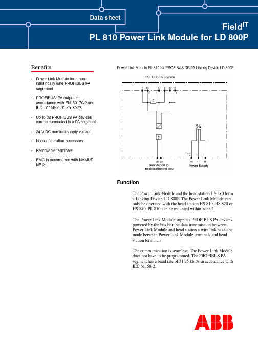
Benefits Data sheetField IT PL 810 Power Link Module for LD 800P Power Link Module PL 810 for PROFIBUS DP/PA Linking Device LD 800PFunctionThe Power Link Module and the head station HS 8x0 forma Linking Device LD 800P. The Power Link Module canonly be operated with the head station HS 810, HS 820 orHS 840. PL 810 can be mounted within zone 2.The Power Link Module supplies PROFIBUS PA devicespowered by the bus.For the data transmission betweenPower Link Module and head station a wire link has to bemade between Power Link Module terminals and headstation terminalsThe communication is seamless. The Power Link Moduledoes not have to be programmed. The PROFIBUS PAsegment has a baud rate of 31.25 kbit/s in accordance withIEC 61158-2.-Power Link Module for a non-intrisincally safe PROFIBUS P Asegement-PROFIBUS P A output inaccordance with EN50170/2 and IEC61158-2; 31.25kbit/s-Up to 32 PROFIBUS P A devices can be connected to a P A segment -24 V DC nominal supply voltage -No configuration necessary-Removable terminals-EMC in accordance with NAMUR NE 21Field ITTecnical DataPowerNominal voltage 20 ... 35 V DCNominal current 790 mA ... 400 mA Ripples< 10 %Galvanic separation CH/PROFIBUS DP Function isolation, designed isolation voltage 50 V eff PROFIBUS PA/Power Function isolation, designed isolation voltage 50 V effCH/PowerFunction isolation nach DIN EN 50178, designed isolation voltage 50 V eff Field bus connection Connection Terminals 3, 18+; 2, 17-Profibus PA in accordance with IEC 61158-2Nominal voltage 24 ... 26 V Nominal current< 400 mATerminator impedance 100 Ohm integrated ProtocolPROFIBUS DP V1Connection to head station Connection Terminals 28+, 29-Baud rate31 kBit/sEntity parameter Approval for zone 2TÜV 02 ATEX 1886 XGroup, Category, ignition protection method II 3 G EEx n A II T4StandardsField bus standard EN 50170/2Galvanic separationEN 50178Electromagnetic compatibility NAMUR NE 21PROFIBUS DP V1 EN 50170/2Protection typeIEC/EN 60529Conformity to Directives Elektromagnetic compatibilityEC-Directive 89/336/EWG StandardEN 61326Explosion protectionEG-Directive EG94/9StandardEN 50021Environmental conditions Ambient temperature -20 ... 60 °C (253 ... 333 K)Relative humidity < 75 %Mechanical data Connection typeTerminals Conductor cross section up to 2,5 mm²Housing 80 mm x 115 mm x 107 mm Mass320 g Protection classIP20Field ITNotesNote:Informationen on installation of PROFIBUS PA can be taken from PTO PROFIBUS user organization guidelines.Number of PA devices, current consumption of the participants:The maximum combined current consumption of the connected PROFIBUS PA devices must be lower than the nominal current of the Linking Device. The modulation current used by the PROFIBUS PA devices to transmit data does not have to be considered.International certificates, declarations of conformity and User Instructions can be retrieved via the search button under .DimensionsFor more information of Field IT ,********************************************.comFor the latest information on ABB visit us on the World Wide Web at /processautomationOur worldwide staff of professionals is ready to meet your needs for process automation.For the location nearest you, please contact the appropriate regional office:Field ITAutomation T echnology Products Mannheim, Germanywww.abb.de/processautomationemail:*********************************.comAutomation T echnology Products Wickliffe, Ohio, USA/processautomationemail:****************************.comAutomation T echnology Products V äster ås, Sweden/processautomationemail:************************.com3BDD011711R0201 Printed in Germany Oktober 2002Copyright © 2002 by ABB Automation Products GmbH, All Rights Reserved ® Registered Trademark of ABB ™ Trademark of ABBAccessoriesFor PROFIBUS PA applications ABB Automation Products offers the following accessories:I Head station HS 810 (1 channel)I Head station HS 820 (2 channel)I Head station HS 840 (4 channel with PROFIBUS DP media redundancy)IUser Instructions Linking Device LD 800P (3BDD011704R0101)Application example。
rtl设计阶段降低功耗常用方法

rtl设计阶段降低功耗常用方法
在RTL设计阶段,降低功耗是一个重要的目标。
通过采用一些常用的方
法可以有效降低功耗并提高电路性能。
可以使用时钟门控技术来降低功耗。
在电路中,时钟信号通常会使大部
分逻辑门进行切换,从而导致功耗的浪费。
通过使用时钟门控技术,可以将
不需要进行切换的逻辑门断开与时钟的连接,从而降低功耗。
这种方法在设
计中常被用于减少动态功耗的消耗。
采用时钟门控技术可以减少动态供电峰值。
时钟边沿触发的逻辑门切换
会导致电路中的供电峰值增加。
为了降低这种动态供电峰值,可以采用手动
插入一些延迟逻辑,将多个逻辑门的切换时间错开,从而减少电路中的同时
切换。
使用数据压缩和编码技术也是降低功耗的有效方法。
数据压缩可以减少
数据传输所需的比特数,从而减少功耗。
编码技术可以将原始数据转换为一
种更紧凑、更高效的编码格式,进一步降低功耗。
合理设计电源网络也可以减少功耗。
通过优化电源网络的连接方式和电
源线的布局,可以减少电路中的功耗损失。
同时,选择低功耗器件和适当设
置电源的供电电压也是有效的功耗降低策略。
在RTL设计阶段,降低功耗是一个需要重视的问题。
采用时钟门控技术、数据压缩和编码技术、合理设计电源网络等方法可以有效降低功耗,并提高
电路的性能和可靠性。
同时,合理的电路布局和器件选择也是降低功耗的关
键因素。
通过综合运用以上方法,可以在RTL设计阶段实现功耗的有效降低。
v810 axi参数设定标准
v810 axi参数设定标准
V810 AXI的参数设定标准包括突发大小和突发类型两部分。
突发大小是指每次突发数据传输或每个节拍中数据的字节数,由ARSIZE[2:0](读传输)或AWSIZE[2:0](写传输)字段指定。
突发大
小的计算公式为:突发大小 = 2^AxSIZE。
如果AXI的总线比突发大小宽,AXI接口每次传输就必须根据地址判断使用哪几条数据线,任何一次传输的大小都不能超过事务中任一代理的数据总线宽度。
突发类型方面,AXI协议定义了三种突发类型:固定(FIXED)、递增(INCR)和回绕(WRAP)。
在固定突发事务中,每次传输的地址一致,有效的字节线也是一致的,但是可以通过WSTRB信号控制实际有效的字节。
这种方式通常用于对
同一位置的重复访问,如读取或清空FIFO时。
在一次递增突发事务中,每次传输,地址都会在之前的地址基础上递增,递增量为传输大小。
当地址到达上界后,回绕突发类型的地址就会回绕到下界,这种类型
和递增方式类似。
华硕AK-W710L使用手册说明书
2 本機特點3 安全注意事項 各部名稱 安裝方法 功能操作456 5 安裝步驟 5 安裝場所 6 功能選擇 6 音量調整 7 CD唱片的使用 7 CD唱片的播放 7 低音加強功能8 搜尋特定歌曲片段 8 重覆播放 8 搜尋特定樂曲 9 隨機播放 9 程序播放記憶 9 清除程序播放記憶 9 耳機的使用13 免責聲明10 保養方法11 故障排除12 緊急處理方法13 關於售後服務在使用本機之前,應仔細閱讀下列事項及使用說明,閱後並請妥為收存,以備將來參考:本機請勿置於雨中、濕氣中或避免陽光直射及遠離其他會產生熱能的裝置。
本機放置位置請勿太靠近電視、電腦、錄影機及手機,以免遭受干擾,產生錯誤動作。
00使用本機的工作溫度為5~35C。
長期不使用本機時,應將其電源線插頭從插座內拔出。
請勿將雜物或液體從機身開口處放進入機身內部。
當本機出現下列情況時,應請合格的維修人員進行維修:A:故障或液體落入本機內。
B:雜物或液體落入本機內。
C:受到雨淋。
D:無法正常操作或性能出現明顯變化。
E:不慎跌落或外殼受損。
請勿擅自拆下任何蓋子、內部裝置或調校內部裝置,請交由本公司專業人員進行維修。
使用耳機時,請勿將音量調太大聲,以免聽力受損。
當耳朵產生耳鳴時,應將音量調小或取消耳機使用。
當使用開放式耳機時,請勿將音量調太大聲,以避免聽不到周遭的聲音。
安裝步驟打開CD蓋,先取出"雷射頭保護紙片"。
交流供電:當插上交流電源插頭後,且 FUNCTION 切在"OFF"位置,表示本機已處於待機狀態。
若不想消耗電源,確保安全,請在不使用時將電源線插頭拔出。
電池供電:打開機底電池蓋,照指示依正負方向放入6個2號電池。
在使用電池時,請將機後插上的交流電源線插頭拔出,如未拔除電源線插頭,電池將無法供電。
安裝場所本機應安裝於陰涼、乾燥、通風、無腐蝕性氣體的地方。
盡量避免放在潮濕或高溫曝曬的地方。
注意事項更換電池時,請將交流電源插頭暫時拔出。
网卡芯片rtl8110s(b-c)-8100c_111_0810

GND
1
R7
GND
*For RTL8110S(B-C) application, change L8 to 0 ohm.
GND
Q2
GND
Q3
Q4 CTRL25
2
If U4 is used, R6 and R7 can be set to 2.7K and 1.2K to have 1.8V output power at RTL8110S application, or set R6(Open) and R7(0) to have 1.25V output power at RTL8110SB application. If external regulator is preferred, replace U4 with AMS1117-1.5 component for RTL8110SC application.
3 2 2SB1188
SPX3940-2.5 OUT 3 ADJ 2
* C29 to C32 are for U7 RTL8110S(B/C)/RTL8100C AVDDL pins, such as 3, 7, 16, and 20.
3
If Q3 is used, remove R5 and keep R4 at RTL8110S & RTL8110SC application, or remove R4 and keep R5 at RTL8110SB application.
CTRL12/18/15 VDD33 3 + C38 10uF C40 .1uF U4
CTRL12/18/15
3 2 CTRL18/25 1 2SB1188
1
Q4
RTL8101E网卡驱动安装过程
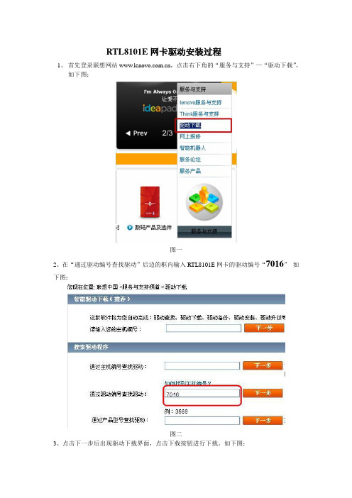
RTL8101E网卡驱动安装过程
1、首先登录联想网站,点击右下角的“服务与支持”—“驱动下载”,
如下图:
图一
2、在“通过驱动编号查找驱动”后边的框内输入RTL8101E网卡的驱动编号“7016”如下图:
图二
3、点击下一步后出现驱动下载界面,点击下载按钮进行下载。
如下图:
图三
4、文件下载成功后找到下载的文件。
如下图:
图四
5、双击文件后点击安装进行解压,如没有设置目标文件夹,文件将解压到当前目录,如下图:
图五
6、解压后找到setup文件,双击启动安装程序。
如下图:
图六
7、启动安装程序后出现安装窗口,点击NEXT 继续。
如下图:
图七
8、出现对话框后点击“Install”继续。
如下图:
图八9、开始安装驱动程序。
如下图:
图九
10、安装完成后提示完成,点击“Finsh”完成安装。
如下图:
图十。
- 1、下载文档前请自行甄别文档内容的完整性,平台不提供额外的编辑、内容补充、找答案等附加服务。
- 2、"仅部分预览"的文档,不可在线预览部分如存在完整性等问题,可反馈申请退款(可完整预览的文档不适用该条件!)。
- 3、如文档侵犯您的权益,请联系客服反馈,我们会尽快为您处理(人工客服工作时间:9:00-18:30)。
Power Consumption of RTL8101L
Environment: Vaux=5V, Novell Server 4.11 w/ RTL8139C, Client
ODI driver, ipxsend.exe.
1. Medium Speed =100Mbps
1. Working State: D0
Current Measured Whole Card (5V) Chip (3.3V) Chip (2.5V) Tx 66 mA 62 mA 20 mA
Rx 75 mA 70 mA 22 mA Tx + Rx 79 mA 72 mA 21 mA
Idle 64 mA 61 mA 20 mA Link Down(W/O Power Saving) 44 mA 40 mA 16 mA Link Down Power Saving 24 mA 20 mA 12 mA
2. Power Down State: (D1, D2, D3hot w/ PCI clock running,
wakeup enabled)
Current Measured Whole Card (5V) Chip (3.3V) Chip (2.5V) Idle 62 mA 59 mA 20 mA Link Down(W/O Power Saving) 44 mA 40 mA 16 mA Link Down Power Saving 24 mA 20 mA 12 mA
3. Power Down State: (D3cold, wakeup enabled)
Current Measured Whole Card (5V) Chip (3.3V) Chip (2.5V) Idle 62 mA 58 mA 18 mA Link Down(W/O Power Saving) 43 mA 39 mA 14 mA Link Down Power Saving 23 mA 20 mA 10 mA
Maximum Power Saving:
Current Measured Whole Card (5V) Chip (3.3V) Chip (2.5V)
5 mA 1 mA 2 mA
2. Medium Speed =10Mbps
1. Working State: D0
Current Measured Whole Card (5V) Chip (3.3V) Chip (2.5V) Tx 85 mA 83 mA 11 mA
Rx 31 mA 30 mA 12 mA Tx + Rx 87 mA 85 mA 12 mA
Idle 28 mA 27 mA 11 mA Link Down(W/O Power Saving) 41 mA 40 mA 15 mA Link Down Power Saving 20 mA 21 mA 11 mA
2. Power Down State: (D1, D2, D3hot w/ PCI clock running, wakeup
enabled)
Current Measured Whole Card (5V) Chip (3.3V) Chip (2.5V) Idle 26 mA 25 mA 11 mA Link Down(W/O Power Saving) 41 mA 40 mA 15 mA Link Down Power Saving 20 mA 21 mA 11 mA
3. Power Down State: (D3cold, wakeup enabled)
Current Measured Whole Card (5V) Chip (3.3V) Chip (2.5V) Idle 25 mA 25 mA 9 mA Link Down(W/O Power Saving) 41 mA 40 mA 13 mA Link Down Power Saving 20 mA 20 mA 9 mA
4. Maximum Power Saving:
Current Measured Whole Card (5V) Chip (3.3V) Chip (2.5V)
4 mA 2 mA 1 mA 3.3V Power level : 2.6V~4.5V
2.5V Power level : 2.2V~4V。
