AxM-II 驱动器样本
广州数控DAT系列交流伺服驱动单元使用手册
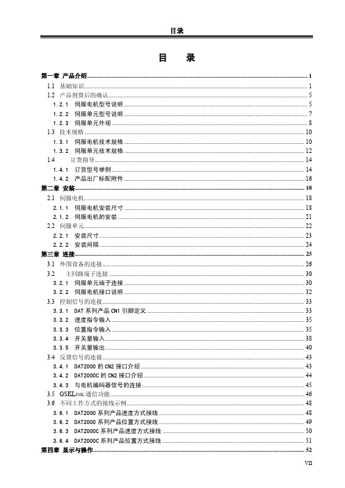
3.3.2 速度指令输入 .............................................................................................................................. 35
3.3.3 位置指令输入 .............................................................................................................................. 35
3.5 GSKLINK 通信功能............................................................................................................................... 46
1.3 技术规格................................................................................................................................................ 10
目录
目录
第一章 产品介绍................................................................................................................................................ 1
3.3.4 开关量输入 .................................................................................................................................. 38
LPMS-B2系列硬件手册说明书
LPMS-B2 Series Hardware Manual ver. 1.0LP-RESEARCH Inc.Version HistoryTable of Contents1.Introduction ....................................................................... - 1 -2.System Overview .............................................................. - 2 -3.Coordinate ........................................................................ - 3 -4.Specification ..................................................................... - 4 -5.Battery Charging .............................................................. - 7 -Charging ........................................................................................ - 7 -LED Indication ............................................................................... - 7 -6.Mechanical Information .................................................... - 8 -1.IntroductionWelcome to the LP-RESEARCH Motion Sensor LPMS-B2 Series hardware manual.In this documentation we will primarily introduce the hardware specifications of LPMS-B2 Series sensors. If you have any further questions or comments regarding this documentation please feel free to contact us anytime.For more information on the LPMS-B2 or other product series, please refer to related datasheets and user manuals, available from the LP-RESEARCH website at the following address: .Table 1-1. LPMS-B2 Series part number informationPart NumberBluetoothClassic 2.0Bluetooth LowEnergy 4.1EnclosureCaseEmbeddedBatteryLPMS-B2 ✓✓✓✓LPMS-B2 OEM ✓✓✗✗2. System OverviewFig. 2.1. LPMS-B2 series sensor structureCharger and Battery UnitMCU3 axis Accelerometer3 axis Gyroscope 3-axis MagnetometerPressure SensorFlash UnitBluetooth UnitData/Command5V DC3.CoordinateThe LPMS sensor calculates the orientation difference between a fixed sensor coordinate system (S) and a global reference coordinate system (G). Both coordinate systems are defined as right-handed Cartesian coordinate systems. The sensor coordinate system (S) is constructed as following images.Z YXZYXFig. 3.1. Sensor coordinates of LPMS-B2 and LPMS-B2 OEMThe global reference coordinate system (G) can be divided into two different cases. While the orientation calculation is using all acceleration, gyroscope and magnetic data (sensor filter mode set at acc+gyr+mag), (G)system is defined as following:•X positive when pointing to the magnetic north•Y positive when pointing to the magnetic west•Z positive when pointing up (gravity points vertically down with -1g)While the orientation calculation is using only acceleration and gyroscope data (sensor filter mode set at acc+gyr), (G) system is defined as following: •X positive aligned to ground plane horizontal projection of x axis of (S) when sensor powered on•Y positive based on right-handed Cartesian coordinate definition•Z positive when pointing up (gravity points vertically down with -1g)4.SpecificationTable 4-1. Overall parametersParameters LPMS-B2LPMS-B2 OEM Output range of Euler angle Roll: ±180°; Pitch: ±90°; Yaw: ±180°Bandwidth400HzResolution<0.01°Accuracy<0.5°(Static), <2°RMS (Dynamic) Max. instant impact (0.1 ms)10,000gOutput data type Raw data/Euler/Quaternion/Linear acceleration/Air pressure/Altitude/TemperatureLatency 20 msInternal sampling rate400Hz Communication interface Bluetooth Classic 2.0 (BLE4.1 Optional) Max. baudrate 921600 bps Communication protocol LPBUSSize39x39x8 mm 16x31x4 mm Weight12 g 2g Communication distance<20mMax. data update rate400HzPower consumption<**********Power supply Lithium Battery > 6h(3.7V@230mAh)3.3-5.5V DCWorking temperature-20~+60 °C -40 ~ +80 °CConnector*Micro USB, type B Micro USB, type B; SM02B-SURS-TF;*LPMS-B2 USB connector is only used for charging, the sensor is powered by the internal embedded lithium battery.Table 4-2. Accelerometer SpecificationParameters Typical Value Unit Measurement range±2/±4/±8/±16 g Sensitivity0.061/0.122/0.244/0.488 mg/LSBLinear accelerationsensitivity changevs. temperature±1 %Linear accelerationtypical zero-g leveloffset accuracy±40 mgLinear accelerationzero-rate changevs. temperature±0.5 mg/°CAcceleration noise density90(FS= ±2 g ODR = 104 Hz)μg/√HzParameters Typical Value Unit Measurement range±125/±245/±500/±1000/±2000 dps Sensitivity 4.375/8.75/17.50/35/70 mdps/LSBAngular ratesensitivity changevs. temperature±1.5 %Angular rate typicalzero-rate level±10 dps Angular rate typicalzero-rate levelchange vs.temperature±0.05 dps/°C Rate noise density7 mdps/√HzTable 4-4. Magnetometer SpecificationParameters Typical Value Unit Measurement range±4/±8/±12/±16 Gauss Sensitivity6842/3421/2281/1711 LSB/gaussZero-gauss level±1(FS=±4 gauss)gaussRMS noise(Ultra-high-perform ance mode)X axis 3.2 mgauss Y axis 3.2 mgauss Z axis 4.1 mgaussNon-linearity±0.12 %FSTable 4-5. Pressure and Humidity Sensor Specification Parameters Typical Value UnitPressuremeasurement range300~1100 hPa Temperaturecoefficient of offset±1.5 Pa/K Absolute accuracypressure±1.0 hPa Pressure sensitivity 0.18 Pa Pressure noise 1.3 Pa Humiditymeasurement range0~100 %RH Humidity accuracy ±3 %RH Humidity latency(10~90~10 %RH,25 °C)±1 %RH Humidity sensitivity 0.008 %RH Humidity noise 0.02 %RH Humidity stability(10~90 %RH,25 °C)0.5 %RH/year5.Battery ChargingChargingThe LPMS-B2 sensor can be charged through the micro USB port. In case of LPMS-B2 OEM, users have to specify the methods of power supply for their own designs.The charging voltage for LPMS-B2 is 5V and the required power current is at least 100mA for an efficient charging progress. Depending on the remaining power in the battery, the on-board LED will show different charging status by different colors. Detailed information of the LED status is introduced in the following section.LED IndicationTable 5-1. LED Status IndicationWork Mode LED Status LED Color Remaining BatteryNormalConnection off Blinking lightBlue >10%Red <10% Connection on Pulsating lightBlue >10%Red <10% Charging Always onGreen >90%Blue 20%~90%Red <20%6.Mechanical InformationFig. 6.1. LPMS-B2 DimensionFig. 6.2. LPMS-B2 OEM DimensionCopyright © 2020, LP-RESEARCH Inc. All rights reserved.。
亿丰电子伺服手册

2.3.3 速度/转矩控制接线图(标准版).......................................................................................- 23 2.3.4 速度/转矩控制接线图(进阶版).......................................................................................- 24 -
第 2 章 接线 .....................................................................................................- 8 -
2.1 系统组成与接线 ................................................................................................ - 8 -
3.2 模式功换.......................................................................................................... - 26 3.3 监控模式(Dn)操作............................................................................................ - 27 3.4 辅助模式(Fn)操作 ............................................................................................ - 27 3.5 用户参数模式(Pn)操作..................................................................................... - 36 -
青蓝 DM556 数字式两相步进驱动器使用说明书

DM556数字式两相步进驱动器一、产品简介1.概述DM556是青蓝科技新推出的数字式步进电机驱动器,采用最新32位DSP技术,用户可以设置200-25600内的任意细分以及额定电流内的任意电流值,能够满足大多数场合的应用需要。
由于采用内置微细分技术,即使在低细分的条件下,也能够达到高细分的效果,低中高速运行都很平稳,噪音超小。
驱动器内部集成了参数自动整定功能,能够针对不同电机自动生成最优运行参数,最大限度发挥电机的性能。
2.特点●全新32位DSP技术●可驱动4、6、8线两相步进电机●低振动低噪声●光隔离差分信号输入●内置高细分●脉冲响应频率最高可达200KHz(更高可改)●参数自动整流功能●电流设定方便,可在1.4-5.6A之间任意选择●精密电流控制使电机发热大为降低●细分设定范围为200-25600●静止时电流自动减半●具有过压、欠压、短路等保护功能3.应用领域适合各种中小型自动化设备和仪器,例如:雕刻机、打标机、切割机、激光照排、绘图仪、数控机床、自动装配设备等。
在用户期望小噪声、高速度的设备应用中应用效果特佳。
二、电气、机械和环境指标1.电气指标说明DM556最小值典型值最大值单位输出电流 1.0- 4.2A输入电源电压203650VDC控制信号输入电流71016mA步进脉冲频率0-200KHz绝缘电阻50MΩ2.使用环境及参数冷却方式自然冷却或强制风冷使用环境场合不能放在其他发热的设备旁,要避免粉尘、油雾、腐蚀性气体,湿度太大及强振动场所,禁止有可燃气体和导电灰尘温度0——50℃湿度40—90%RH 振动10~55Hz/0.15mm 保存温度-20℃~65℃重量280克3.机械安装图图1安装尺寸图(单位:mm)※推荐采用侧面安装,散热效果更佳,设计安装尺寸时,注意考虑端子大小及布线!4.加强散热方式1)驱动器的可靠工作温度通常在50℃以内,电机工作温度为80℃以内;2)建议使用时选择自动半流方式,马达停止时电流自动减一半,以减少电机和驱动器的发热;3)安装驱动器时请采用竖着侧面安装,使散热齿形成较强的空气对流;必要时机内靠近驱动器处安装风扇,强制散热,保证驱动器在可靠工作温度范围内工作。
MAX232 5V 双通道 RS-232 驱动 接收器 说明书

FEATURES●Output voltage levels are compatible with input levelsof CMOS and TTL integrated circuits●Meets All EIA/TIA-232E and V.28/V.24 Specifications ●Supply voltage range from 4.5 to 5.5V●Low input current: 1.0µA at 25°C●Output current 24mA●Tolerable value of static potential not less than 2kV ●Available in DIP-16 PackageAPPLICATIONS●Portable Computers●Battery-Powered RS-232 Systems●Interface Translation●Low-Power Modems●TerminalsDIP-16ORDERING INFORMATIONDevice Package MAX232EN DIP-16 * Refer to the ordering information for the details.DESCRIPTIONThe MAX232 is a dual driver/receiver of RS-232 standard with a single supply voltage and bipolar output voltage of the transmitter formed by a built-In voltage multiplying generator on four 1.0µF external capacitors, designed for use in state-of-the-art high performance computing systems, high-speed electronic devices with high reliability of information exchange between remote objects.Input voltage levels are compatible with standard CMOS and TTL levels.ABSOLUTE MAXIMUM RATINGSPARAMETER SYMBOL MIN. MAX. UNIT Supply Voltage V CC-0.3 6.0 V Transmitter High Output Voltage V+V CC-0.3 14 V Transmitter Low Output Voltage V--14 0.3 V Transmitter Input Voltage V TIN-0.3 V++0.3 V Receiver Input Voltage V RIN-30 30 V Voltage Applied to Transmitter Output V TOUT V--0.3 V++0.3 V Voltage Applied to Receiver Output V ROUT-0.3 V CC+0.3 V Storage Temperature Range T STG-65 150 °CHTC1RECOMMENDED OPERATING CONDITIONSPARAMETER SYMBOL MIN. MAX. UNIT Supply Voltage V CC 4.5 5.5 V Transmitter Input Voltage V TIN0 V CC VReceiver Input Voltage V RIN-30 30VOutput Current of Transmitter Short Circuit I SC- ±60 mA Ambient Temperature Range T A-40 +85 °CORDERING INFORMATIONPackage Oder No. Package Marking Compliance Supplied AsDIP-16 MAX232EN MAX232E RoHS, Green TubeHTC2PIN CONFIGURATIONC1+V+C1-C2+C2-V-T2OUT R2INVCCGNDT1OUTR1INR1OUTT1INT2INR2OUT DIP-16 PKGPIN DESCRIPTIONPin No. Pin Name Pin Description1 C1+ Terminal for Positive Charge-Pump C1 Capacitor2 V+ Positive Voltage Generated by the Charge-Pump3 C1- Terminal for Negative Charge-Pump C1 Capacitor4 C2+ Terminal for Positive Charge-Pump C2 Capacitor5 C2- Terminal for Negative Charge-Pump C2 Capacitor6 V- Negative Voltage Generated by the Charge-Pump7 T2OUT RS-232 Driver Output (Levels RS-232)8 R2IN RS-232 Receiver Input (Levels RS-232)9 R2OUT RS-232 Receiver Output (Levels TTL/CMOS)10 T2IN RS-232 Driver Input (Levels TTL/CMOS)11 T1IN RS-232 Driver Input (Levels TTL/CMOS)12 R1OUT RS-232 Receiver Output (Levels TTL/CMOS)13 R1IN RS-232 Receiver Input (Levels RS-232)14 T1OUT RS-232 Driver Output (Levels RS-232)15 GND Ground16 VCC Supply Voltage InputHTC3TYPICAL APPLICATION CIRCUITFUNCTION TABLEINPUT (RIN, TIN)OUTPUT (ROUT, TOUT)L (Low Level) H (High Level)H (High Level) L (Low Level)HTC 4ELECTRICAL CHARACTERISTICS(Limits in standard typeface are for T A=25°C, and the limits in boldface type apply over full operating temperature range.) PARAMETER SYMBOL TEST CONDITIONS MIN. TYP. MAX. UNITSupply Current I CC V CC = 5.5VV IL = 0V- -10.014.0mAReceiver ParametersHysteresis Voltage V h V CC = 5.0V 0.20.2-0.91.0VOn (Operation) Voltage V on V O≤ 0.1V, I OL≤ 20µA - - 2.42.3VOff (Dropout) Voltage V off V O≥ V CC - 0.1VI OH≤ -20µA0.80.9- - VOutput Low Voltage V OL I L = 3.2mA, V CC = 4.5V,V IH = 2.4V- -0.30.4VOutput High Voltage V OH I OH = -1.0mA, V CC = 4.5V,V IL = 0.8V3.63.5- - VInput Resistance R I V CC = 5.0V 3.03.0-7.07.0kΩTransmitter ParametersOutput Low Voltage V OL V CC = 4.5V, V IH = 2.0V,R L = 3.0kΩ- --5.2-5.0VOutput High Voltage V OH V CC = 4.5V, V IL = 0.8V,R L = 3.0kΩ5.25.0- - VInput Low Current I IL V CC = 5.5V, V IL = 0V - --1.0-10.0µAInput High Current I IH V CC = 5.5V, V IH = V CC- -1.010.0µASpeed Of Output Front Charge SR V CC = 5.0V, C L = 50 - 1000pF,R L = 3.0 - 7.0kΩ3.02.7-3027V/µsOutput Resistance R O V CC = V+ = V- = 0VV O = ±2V350300- - ΩShort Circuit Output Current I SC V CC = 5.5VV O = 0VV I = V CC- --50-60mAV I = 0 - -5060Speed Of Information Transmission STV CC = 4.5V, C L = 1000pF,R L = 3.0kΩ, t W = 7µs (forextreme, t W = 8µs)140120- - kbit/sDynamic ParametersSignal Propagation Delay Time When Switching On (Off)t PHLR(t PLHR)V CC = 4.5V, C L = 150pF,V IL = 0V, V IH = 3.0V,t LH = t HL≤ 10ns- -9.710.0µsSignal Propagation Delay Time When Switching On (Off)t PHLT(t PLHT)V CC = 4.5V, C L = 2500pF,V IL = 0V, V IH = 3.0V,R L = 3kΩ, t LH = t HL≤ 10ns- -5.06.0µsHTC5TIMING DIAGRAM0VV OHV OLFigure 1. t PHL and t PLH waveforms of Receiver0VV OHV OLFigure 2. t PHL and t PLH waveforms of Transmitter6HTCFigure 3. t SLH and t SHL waveforms of Transmitter7HTCREVISION NOTICEThe description in this data s heet is subject to change without any notice to describe its electrical characteristics properly.8HTC。
步进电机驱动器--MA860H说明书
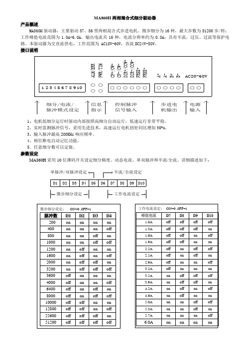
MA860H 两相混合式细分驱动器
产品概述
MA860H 驱动器,主要驱动57、86型两相混合式步进电机。
微步细分为16种,最大步数为51200步/转;工作峰值电流范围为1.0A-6.0A ,输出电流共16种,电流分辨率约为0.3A ;具有半流,过压、过流等保护电路。
本驱动器为交直流供电,工作范围为 AC18V-60V ,直流DC24V-80V 。
接口说明
B
+B -9C P -/C W -A +A -D I R -/C C W -F R E E +D I R +/C C W +F R E E -
P W R /T I M
C P +/C W +
10
A
L M
/E R
R 523
487
61AC20-60V
步进电机输出
控制脉冲信号输入电源输入
信息指示细分/电流/脉冲模式设定
1、电机低细分运行时驱动内部按照高细分自动运行,低速运行非常平稳。
2、实时监测脉冲信号,采用先进技术,高速运行电机扭矩同比增加30%。
3、输入脉冲最高200KHz 响应频率。
4、相位断电自动记忆功能。
5、任意细分数可以定做。
参数设定 MA860H 采用10位薄码开关设定细分精度、动态电流、单双脉冲和半流/全流。
详细描述如下:
D1
D2
D3
D4
D5
D6
D7
D8
D9D10
微步细分设定工作电流设定
单脉冲/双脉冲设定半流/全流设定。
美国AEM Corporation 产品说明书:6522、6526、6534和6536模型的 Lis

L I ST E D®USCIP 54Easy To Use● Selectable test voltages from 10 to 1000V (model dependent)● Insulation resistancemeasurement up to 200GΩ (model dependent)● Automatic discharge at the completion of the test● Manual, Lock & Timer test modes ● PI / DAR Ratio calculations (model dependent)● Active voltmeter detects live voltage prior to starting a test ● Automatic test inhibition if live voltage above 25 volts detected ● 200mA / 20mA continuity measurement with active protection without fuses● Measures V (AC & DC), Hz, Ω,kΩ, capacitance and cable length (model dependent)● ∆REL mode for comparative measurements displayed as a value or %● Test lead compensation eliminates lead resistance from continuity measurements● Data storage of test results (model dependent)● Computer report generation of test results (model dependent)Models 6522, 6526, 6534 & 6536Handheld MegohmmetersTechnical Hotline: (800) 343-1391Our products are backed by over 130 years of experience in test and measurement equipment, and encompass the latest international standards for quality and safety.Insulation Resistance Testers Including Multimeter FunctionsMΩ Technical Assistance (800) 343-1391Ideal for testing cables, small motors, pumps,transformers and industrial equipmentINDUSTRIAL MAINTENANCEModels 6522 & 6526►FEATURES▪Simple to use, handheld, compact and lightweight▪General purpose multimeter functions including voltage,frequency, resistance, continuity and capacitance(model dependent)▪Spot test and timed insulation resistance measurement▪PI and DAR ratios calculated to determine the quality ofthe insulation independent of ambient temperature(model dependent)▪∆REL function enables measurement of the differencebetween a reference value and new measured value(Model and 6526)▪Data storage allows comparison of results with previous testand report generation (Model 6526)▪Alarms with Green/Red Pass/Fail indicator light (Model 6526)▪FREE DataView® software for configuring real-timecommunication with a PC and report generation withpre-defined or user defined templates for use with Model 6526▪Bluetooth (Class 2 wireless communication from up to 30 ft a way) with Model 6526Model 6526onlyModel 6526Model 6522MEGOHMMETERSALARM MEM VAR HOLDDARPIT1T2M ΩTELECOM & ELECTRONICS & SPECIAL APPLICATIONSModel 6534 & 6536DESCRIPTION Megohmmeter Model 6534 (Digital w/Analog Bargraph, Alarm, 10V , Ohm, Continuity, V , kΩ, Mem, w/DataView ® Software) ����������������������������������������������������������������������������������������������������������������������������������������������������������������������������Ideal for insulation measurements onelectronic components and circuits, Ethernet cables and other low voltage DC wiringMODEL 6534► FEATURES▪ Simple to use, handheld, compact and lightweight ▪ 10 to 500V insulation test voltage selection▪ Insulation resistance measurement from 2kΩ to 50GΩ▪ Compatible with the specific requirements of the electronics industry for both low current applications and power stages ▪ ∆REL function enables measurement of the difference between a reference value and new measured value▪ FREE DataView ® software for configuring real-time communication with a PC and report generation with pre-defined or user defined templates ▪ Bluetooth (Class 2 wireless communication from up to 30 ft away)▪ General purpose multimeter functions including voltage, resistance & continuityMODEL 6536► FEATURES▪ Simple to use, handheld, compact and lightweight▪ Variable test voltage selection from 10 to 100V in 1V increments ▪ Insulation resistance measurement from 2kΩ to 20GΩ▪ Covers the specific requirements which require a low testvoltage and strict dherence to testing procedures▪ ∆REL function enables measurement of the difference between a reference value and new measured value▪ Test lead compensation eliminates lead resistance from continuity measurements▪ General purpose multimeter functions including voltage resistance and continuity▪ Available in an optional ESD Floor Test KitIdeal for special applications in the aerospace and defense sectors and for ESD testing where specific test voltages are requiredMegohmmeter Model 6536 (Digital w/Analog Bargraph, Alarm, Variable 10V to 100V , kΩ) �������������������������������������Megohmmeter Model 6536 ESD Floor Test Kit ���������������������������������������������������������������������������������������������������������������������������������������M ΩTechnical Assistance (800) 343-1391HOW TO CHOOSE THE RIGHT MEGOHMMETER FOR YOUR APPLICATION NEEDSSPECIFICATIONS1000V ModelsALARM MEM VAR DARPI T1T2Technical Assistance (800) 5SPECIFICATIONS1000V ModelsSPECIFICATIONS 6522INSULATION TESTS Test Voltages(250, 500, & 1000) V(50, 100, 250, 500 &1000) V Measurement Range:10 V –25 V –% per GΩ; 1000 V: 0.1 % per GΩ (3) 10 % / U N is added per 100 M ΩT1T2M Ω6 Technical Assistance (800) 343-1391FRONT/TOP PANEL & FUNCTIONAL DISPLAYSModel Dependent– Input terminalRemote probe connection Alarm activation / DeactivationTEST buttonREL set andcompare multimeter❑ FUNCTIONAL DISPLAY1234Main displayFunction indicatorsSecondary display Bargraph display of insulation measurement 1234NOTE:Buttons & FunctionsAre Model DependentALARMMEM VAR HOLD DARPI T1T2Technical Assistance (800) 7DATAVIE W SOFTWAREFor Models 6526 and 6534DataView ® Software automatically recognizes theinstrument when it is connected to the PC and opens the corresponding control panel� The tree structure menu offers users direct access to the data recorded in the instrument and its configuration�Other Functions Available:▪ Start and stop tests from your PC ▪ Real-time display of active tests▪ DAR and PI ratio programming and display ▪ Graphical plot of the tests▪ Generate reports from test resultsData Analysis & Reporting SoftwareStop a test in progress and display the test results.Select test conditions and start a test from the PC and display real-time measurement results graphically�Select individual or multiple tests to download and review on your computer�Status screen allows you to assign a unique name for the instrument and to check and clear memory as needed�Configuration screen allows you to set alarm lev-els, test time and to read and write configurations from and to the instrument�Tree structured status screen provides the ability toselect connected instruments, configure instruments, see the instrument's status and review stored test results�The Megohmmeter Test Probe provides the ability to access test points at distances and places where it isnot practical to initiate the test from the front panel of the instrument�The test button on the probe is active for allMegohmmeter switch positions on the instrument and will initiate an insulation test when pressedFor multimeter functions, the probe is active without the need to press the Test button�The probe is equipped with a flashlight function that can be activated to illuminate the area around the test point�The probe tip is removable and replaceable�Megohmmeter Test Probe Catalog #2155.75► OPTIONAL ACCESSORIESThe Model 6536 is also available as a floor kit. The kit contains the meter, two 5 pound (2�3 kg) floor weights, also referred to as NFPA probes, that are in compliance with EOS/ESD 11�11 specifications� Each floor weight is coated with insulative paint and a conductive rubber base� The instrument, floor weights and test leads are packaged in a rugged field case� The kit provides all the necessary elements for compliance The system is ideal for testing both point to ground and point to point ESD Megohmmeter Model 6536 ESD Floor Test KitCatalog #2155.57HOLDM ΩORDERING INFORMATION & ACCESSORIESAll Models► ORDERING INFORMATION Included with Model 6534(batteries and quick start guide, not shown)The Continuity Probe facilitatescontinuity measurements on multiple points that are in hard to reach areas or areas in close proximity to dangerous voltages�Continuity Probe AEMC ® Instruments • 15 Faraday Dr. • Dover, NH 03820 USA • (800) 343-1391•Fax(603)742-2346•E-mail:**************Export Department: +1 (603) 749-6434 x520 • Fax +1(603)742-2346•E-mail:***************© 2003 Chauvin Arnoux ®, Inc. d.b.a. AEMC ®Instruments Call the AEMC ® Instruments Technical Assistance Hotline for immediate consultation with an applications engineer: (800) 343-1391950.BR-6500SERIES_0923 • Printed in the USA To learn more, visit 。
AxN驱动器用户手册 V1.1 内部版
用户手册
支持型号
AxN Size3: AxN 22.44.4、AxN 35.70.4、AxN 50.100.4 AxN Size4: AxN 70.140.4 AxN Size5: AxN 90.150.4、AxN 110.200.4
2 . 技术指标..............................................................................................................................11 2.1 AxN Size 3 (AxN 22.44.4; AxN 35.70.4; AxN 50.100.4) ................................................12 2.2 AxN Size 4 (AxN 70.140.4) ...........................................................................................17 2.3 AxN Size 5 (AxN 90.150.4; AxN 110.200.4) .................................................................20 2.4 AxN 系列驱动器环境条件 .........................................................................................24
1
AxN 可编程运动控制平台
4.4.14 EtherCAT IN/OUT——EtherCAT 端口..............................................................83 4.4.15 U1/U2——用户自定义端口 ..........................................................................84 4.4.16 U3/U4——隔离的用户自定义端口(选配) ...............................................86 5 . 附录:选配件......................................................................................................................88 5.1 电机动力线.................................................................................................................89 5.2 编码器线(搭配菲仕电机使用).............................................................................90
使用说明书(第二版)
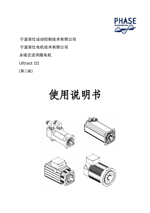
宁波菲仕运动控制技术有限公司宁波菲仕电机技术有限公司永磁交流伺服电机Ultract III(第二版)使用说明书目录一、概述 (3)二、规范说明 (3)三、检查 (3)四、安装 (4)五、编码器配置 (4)六、接线 (6)七、PHASE电机与驱动器接线 (10)Ⅰ、匹配PHASE驱动器接线 (10)(1)、配置正余弦编码器接线 (10)(2)、配置绝对值编码器接线 (11)(3)、配置旋转变压器接线 (12)Ⅱ、匹配LENZE驱动器接线 (13)(1)、配置旋转变压器接线 (13)(2)、配置绝对值编码器接线 (14)(3)、配置数字增量式编码器接线 (15)Ⅲ、匹配KEB驱动器接线 (16)(1)、配置正余弦编码器接线 (16)(2)、配置旋转变压器接线 (17)(3)、配置绝对值编码器接线 (18)Ⅳ、匹配SIEMENS驱动器接线 (19)(1)、配置正余弦编码器接线 (19)(2)、配置旋转变压器接线 (20)Ⅴ、匹配Schneider驱动器接线 (21)(1)、配置旋转变压器接线 (21)(2/3)、配置绝对值编码器接线 (22)Ⅵ、匹配B&R驱动器接线 (24)(1)、配置绝对值编码器接线 (24)Ⅶ、匹配CT驱动器接线 (25)(1)、配置绝对值编码器接线 (25)Ⅷ、匹配Kinwaytech(御能)驱动器接线 (26)(1)、配置旋转变压器接线 (26)Ⅸ、匹配Inovance(汇川)、Modrol(蒙德)驱动器接线 (27)(1)、配置旋转变压器接线 (27)Ⅹ、匹配Vector(威科达)驱动器接线 (28)(1)、配置数字增量式编码器 (28)八、运行与维护 (29)衷心感谢您选用菲仕伺服电机,为使本电机一直维持良好的运行状态,请将本手册随整机附送给最终用户。
虽然在您的选型过程中,可能已经对本产品有所了解并与本公司的技术人员进行了某些沟通,但为充分发挥本电机最佳功能,仍请在使用前,仔细阅读本使用说明书,必要时请与PHASE的有关人员联系,获得必要的帮助,以便正确的使用和维护电机,使之运行可靠,经久耐用。
PCB800099-TTL-LVDS-HDMI-2AV-1VGA驱动板规格书
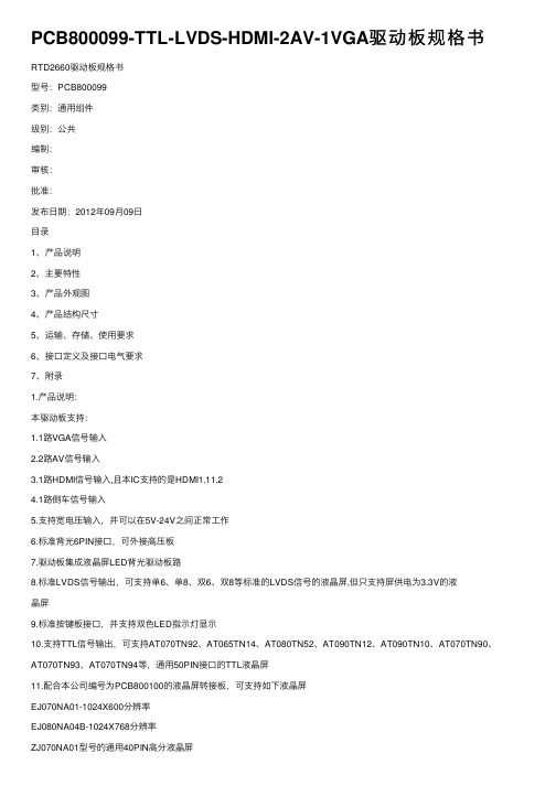
PCB800099-TTL-LVDS-HDMI-2AV-1VGA驱动板规格书RTD2660驱动板规格书型号:PCB800099类别:通⽤组件级别:公共编制:审核:批准:发布⽇期:2012年09⽉09⽇⽬录1、产品说明2、主要特性3、产品外观图4、产品结构尺⼨5、运输、存储、使⽤要求6、接⼝定义及接⼝电⽓要求7、附录1.产品说明:本驱动板⽀持:1.1路VGA信号输⼊2.2路AV信号输⼊3.1路HDMI信号输⼊,且本IC⽀持的是HDMI1.11.24.1路倒车信号输⼊5.⽀持宽电压输⼊,并可以在5V-24V之间正常⼯作6.标准背光6PIN接⼝,可外接⾼压板7.驱动板集成液晶屏LED背光驱动板路8.标准LVDS信号输出,可⽀持单6、单8、双6、双8等标准的LVDS信号的液晶屏,但只⽀持屏供电为3.3V的液晶屏9.标准按键板接⼝,并⽀持双⾊LED指⽰灯显⽰10.⽀持TTL信号输出,可⽀持AT070TN92、AT065TN14、AT080TN52、AT090TN12、AT090TN10、AT070TN90、AT070TN93、AT070TN94等,通⽤50PIN接⼝的TTL液晶屏11.配合本公司编号为PCB800100的液晶屏转接板,可⽀持如下液晶屏EJ070NA01-1024X600分辨率EJ080NA04B-1024X768分辨率ZJ070NA01型号的通⽤40PIN⾼分液晶屏12.配合PCB800100,还可⽀持4.3、5、6、7⼨40PIN通⽤的屏,定义参见AT0543TN24V.113.本驱动板最⼤输出显⽰分辨率为1920X1080超过1440X900显⽰分辨率时,需要视IC的⼯作情况,增加散热⽚,以降低IC的⼯作温度)14.VGA部分可以直接输⼊YPBPR信号,通过程序实现15.本驱动板可增加遥控功能(需要通过软件实现)16.本驱动板可以⾃动检测,并显⽰相关的输⼊电压信息---注:此功能为定制功能,需要联系我公司技术部17.本驱动板可以⽀持⾃动检测信号开关机功能,--此功能为定制功能18.本驱动板可以加BNC接⼝---需要定制19.⽀持倒车控制,并显⽰AV2上,倒车电压⽀持50V以内的电压输⼊20.本驱动板定位孔为四个21.如果特殊要求,我司可以提供其它的定制服务22.客户需要改程序,需要连接我司烧录⼯具,购买相关的程序下载板,23.利⽤本公司的USB接⼝程序下载板,可以⾃⾏在BIN代码上添加LOGO2.主要特性输⼊信号:VGA(0.7Vp-p),AV(CVBS)VGA模式:640*480,800*600.1024768,1280*800,1366*768....1920*1080,1920*1440注意,在输⼊信号超过1440X900时,建议在主IC,RTD2660上加散热⽚,以防IC⼯作温度过⾼引起IC 保护AV模式:⽀持PAL NTSC⽀持背光:LED⾳频功效:不⽀持操作⽅式:按键板,遥控板菜单功能:亮度,对⽐度,⾃动校正,⾏场位置,⾊彩调整⾃动关机语种:中英等多国语⾔电源输⼊:5-24V(+/-0.6V)(DC)⽀持宽电压输⼊可按要求订做电源操作:正常⼯作模式,低功耗模式功耗: 3.0W(⽆负载时)尺⼨:90.5mm(L)×60.6mm(W)×10mm(H)PCB厚度看客户要求定做8mmOEM:可按客户要求重新设计2.接⼝功能说明位号功能说明备注RCA1A V输⼊TP1A V信号输⼊和倒车电压输⼊⼝J4VGA输⼊DB15VGA输⼊HDMI HDMI输⼊HDMI标准为1.11.2 DCIN电源输⼊J3电源输⼊J1外接⾼压板⼝J7LED背光座TTL OUT TTL-50PIN信号输出LVDS OUT LVDS信号输出J6按键,遥控,LED指⽰灯接⼝5.产品外观图6.产品尺⼨图7接⼝功能详细说明J6.按键板,遥控器输⼊接⼝序号定义说明15V遥控器供电,实为3.3V 2GND地3IR遥控输⼊4POWER开关机功能5MENU菜单显⽰功能6+加7--减8SOURCE信号源转换9LED-R LED指⽰灯10LED-G LED指⽰灯DB15--VGA信号输⼊接⼝序号定义说明1SDA⼯⼚测试⽤2SCL⼯⼚测试⽤3GND地4B蓝基⾊5GND地6G绿基⾊7GND地8R红基⾊9GND地10H⾏同步信号11V场同步信号12GND地J1⾼压板接⼝1+12V正电源输⼊2+12V正电源输⼊3EN⾼压板开关信号4空空5GND GND6GND GNDLVDS OUT定义序号定义说明1VCC液晶屏供电2VCC液晶屏供电3VCC液晶屏供电4GND地5GND地6GND地7LAX0+LVDS信号8LAX0-LVDS信号9LAX1+LVDS信号10LAX1-LVDS信号11LAX2+LVDS信号12LAX2-LVDS信号13GND地14GND地15LACK+LVDS信号16LACK-LVDS信号17LAX3+LVDS信号18LAX3-LVDS信号19LBX0+LVDS信号20LBX0-LVDS信号21LBX1+LVDS信号22LBX1-LVDS信号23LBX2+LVDS信号24LBX2-LVDS信号25GND地26GND地27LBCK+LVDS信号28LBCK-LVDS信号29LBX3+LVDS信号30LBX3-LVDS信号J3.DC IN电源接⼝1+12V正电源输⼊2+12V正电源输⼊3GND GND4GND GNDHDMI接⼝1HDMI标准接⼝标准线材可⽤J5.AV信号和倒车控制电源接⼝1ACC倒车电压输⼊,12V输⼊后强制到AV2 2AV1AV1输⼊3GND GND4AV2AV2输⼊5GND GNDJ4-VGA IN1GND GND2V场同步信号3H⾏同步信号4GND GND5R R6GND地7G G8GND地9B B10GND地11SDA升级⽤12SCL升级⽤TTL OUT接⼝定义序号定义描述1VLED+Power for LED backlight(Anode) 2VLED+Power for LED backlight(Anode) 3VLED-Power for LED backlight(Cathode) 4VLED-Power for LED backlight(Cathode) 5GND Power ground6VCOM Common voltage7DVDD Power for Digital Circuit8MODE DE/SYNC mode select9DE Data Input Enable10VS Vertical Sync Input11HS Horizontal Sync Input12B7Blue data(MSB)13B6Blue data14B5Blue data15B4Blue data16B3Blue data17B2Blue data18B1Blue data19B0Blue data(LSB)20G7Green data(MSB)21G6Green data22G5Green data23G4Green data24G3Green data25G2Green data26G1Green data27G0Green data(LSB)28R7Red data(MSB)29R6Red data30R5Red data31R4Red data32R3Red data33R2Red data34R1Red data35R0Red data(LSB)36GND Power Ground37DCLK Sample clock38GND Power Ground39L/R Left/right selection 40U/D Up/down selection 41VGH Gate ON Voltage42VGL Gate OFF Voltage 43AVDD Power for Analog Circuit 44RESET Global reset pin. 45NC No connection46VCOM Common Voltage 47DITHB Dithering function 48GND Power Ground49NC No connection50NC No connection8.运输,存储,使⽤要求1.勿受重压及弯折变形2.防静电和⽔3.相对湿度:≤80%4.存储温度:-10~+60℃5.使⽤温度:0~+40℃本驱动板可使⽤遥控器图⽚(选配)SW1:电源开关键。
MAX232中文资料(官方版)
新一代 器件特性 ____________________________
♦ 对于低电压、集成 ESD 保护的应用 MAX3222E/MAX3232E/MAX3237E/MAX3241E/ MAX3246E:+3.0V 至 +5.5V、低功耗、速率高达 1Mbps、利用四个 0.1µF 电容实现真正的 RS-232 收发器 (MAX3246E 提供 UCSPTM 封装 )。 ♦ 对于低成本应用 MAX221E:±15kV ESD 保护、+5V、1µA、 具有 AutoShutdownTM 功能的单芯片 RS-232。
________________________________ 应用
便携式计算机 低功耗调制解调器 接口转换 电池供电 RS-232 系统 多点 RS-232 网络
_____________________________ 定购信息
PART MAX220CPE MAX220CSE MAX220CWE MAX220C/D MAX220EPE MAX220ESE MAX220EWE MAX220EJE MAX220MJE TEMP RANGE 0°C to +70°C 0°C to +70°C 0°C to +70°C 0°C to +70°C -40°C to +85°C -40°C to +85°C -40°C to +85°C -40°C to +85°C -55°C to +125°C PIN-PACKAGE 16 Plastic DIP 16 Narrow SO 16 Wide SO Dice* 16 Plastic DIP 16 Narrow SO 16 Wide SO 16 CERDIP 16 CERDIP
步进驱动器MA-2202_用户手册

3
版本. 1.1 4/1/2011
SAMSR MOTOR
1.2 功能框图
80~135VAC
AC Input
135~265VAC
MA-2202
Block Diagram
Step Res 1 Step Res 2 Step Res 3 Step Res 4 Current Set 1 Current Set 2 Current Set 3 Idle Current
接大地
防雷器
(功能:吸收电网上的雷击高压脉冲, 推荐防雷器型号: OBV1-D20/2-320 Wenzhou Chuangjie Lightning Protection Electrical Co.,Ltd)
断路保护器模块 (MCCB)
(功能:电路过流或短路 时切断电源)
噪声滤波器
(功能:吸收减小电源线上的 干扰噪声及杂波 推荐型号: 5500.2062 Schurter Inc.)
MA-2202
两相步进电机驱动器 用户手册 V.1.1
版本:1.1 4/1/2011
SAMSR MOTOR
目录 1 简介 ............................................................................................. 3
7.2.1 电气规格 ..................................................................................................17 7.2.2 环境规格 ..................................................................................................17
信捷伺服手册
在产品使用过程中可能引发的问题基本载入了安全注意事项,并且全部以注意和危险两个等级来 注明,其他未竟事项,请遵守基本的电气操作规程。
注意
错误使用时,可能会产生危险,有可能受到中度的伤害或受轻伤的情况下,以 及有可能造成财产损失的情况下。
危险
错误使用时,可能会产生危险,引发人身伤亡或者受到严重伤害,以及有可能 造成严重的财产损失的情况下。
或损失时,请自行设置后备及安全功能。
责任申明
z 手册中的内容虽然已经过仔细的核对,但差错难免,我们不能保证完全一致。 z 我们会经常检查手册中的内容,并在后续版本中进行更正,欢迎提出宝贵意见。 z 手册中所介绍的内容,如有变动,请谅解不另行通知。
联系方式
如果您有任何关于本产品的使用问题,请与购买产品的代理商、办事处联系,也可以直接与信 捷公司联系。 z 电话:0510-85134136 85123803 z 传真:0510-85111290 z 地址:无锡市滴翠路 100 号创意产业园 7 号楼 4 楼 z 邮编:214072
2 产品的安装.......................................................................................................................................... 5 2-1.伺服电机 ................................................................................................................................ 5 2-1-1.保存温度 ...................................................................................................................... 5 2-1-2.安装场所 ...................................................................................................................... 5 2-1-3.同心度 .......................................................................................................................... 5 2-1-4.安装方向 ...................................................................................................................... 6 2-1-5.防止水滴和油滴的措施 .............................................................................................. 6 2-1-6.电线的张紧度 .............................................................................................................. 6 2-2.伺服驱动器 ............................................................................................................................ 6 2-2-1.保存温度 ...................................................................................................................... 6 2-2-2.安装场所 ...................................................................................................................... 6 2-2-3.安装方向 ...................................................................................................................... 6 2-2-4.安装标准 ...................................................................................................................... 7
施耐德_伺服驱动器__伺服电机选型手册

快速启动模式和图形化参数设定
Lexium 23 Plus SET UP 软件提供快速启动模式,可以在一个操作模式中设定必需的功 能。软件提供方便的导航界面。
所有的参数可以通过图形化参数设定实现可视化。可以提供给专家用户高度的灵活 性和高效率。
自动调谐
Lexium 23 Plus SET UP 提供自动调谐功能,共有两种模式: b 离线模式:此模式可以根据用户选择的条件来计算增益参数。 b 在线模式:此模式可以根据机器实际运行的响应来动态计算增益参数,从而提供 对机器最好的控制。
示波器功能
Lexium 23 Plus SET UP 提供强大的示波器功能,可以采用两种模式: b 快速滤波:用于实时检测测量值的变化。 b 精确滤波:用于捕捉应用中的一个非常精确的时刻。此功能在显示信息之前记录 所有的信息,可以用于更精确地调谐。
3
选型指导
Lexium 23 Plus 运动控制
BCH 伺服电机
BCH 伺服电机
2
概览 ( 续 )
共振点抑制前 共振点抑制后
0 Lexium 23 Plus 运动控制
0
Lexium 23 Plus SET UP 调试软件
智能软件界面
Lexium 23 Plus SET UP 调试软件拥有友好的图形用户界面,功能强大,大大缩短了调 整和诊断的时间。 Lexium 23 Plus SET UP 调试软件提供以下功能: b 自动识别通讯格式 b 快速启动模式和图形化参数设置 b 自动和手动调谐 b 共振点检测和 FFT 分析 b 示波器功能
2DM2280-步进电机驱动器

2DM2280数字步进驱动器用户手册本手册的所有内容,著作财产权归公司所有,未经公司许可,任何单位或个人不得随意仿制、拷贝、撰抄。
本手册无任何形式的担保、立场表达或其它暗示。
如有本手册所提到的产品的信息,所引起的直接或间接的资料流出,导致利益损失后果,公司与所属员工不承担任何责任。
除此以外,本手册提到的产品及其资料仅供参考,内容如有更新,恕不另行通知。
版权所有,不得翻印。
版本编写核准V1.0研发部研发部1目录目录 (2)一、概述 (3)二、特点 (3)三、端口说明 (4)3.1控制信号输入端口 (4)3.2ALM信号输出端口 (5)3.3功率端口 (6)四、技术指标 (7)五、控制信号接线 (8)5.1控制信号单端共阳极接线 (8)5.2控制信号单端共阴极接线 (9)5.3控制信号差分接线方式 (10)5.4232串口通信接线图 (11)5.5控制信号时序图 (11)六、拨码开关设定 (13)6.1电流拨码设置 (13)6.2停止电流设定 (13)6.3细分拨码设置 (14)七、错误报警及LED灯闪烁次数 (15)八、安装尺寸 (16)九、接线图 (16)十、参数设置 (18)十一、常见问题及故障处理 (21)11.1电源灯不亮 (21)11.2上电亮红灯报警 (21)11.3脉冲输入后不转动 (21)2一、概述2DM2280是数字式两相步进驱动,采用最新的32位DSP 进行控制。
此数字驱动器外设细分、电流拨码,用户可根据需要自由设置,内部DSP编写先进驱动控制算法,能保证步进电机在各速度段精准、稳定运行,其中,内置细分算法,能使电机在低转速时平稳运行;中高速力矩补偿算法,能最大限度的提高电机中高转速时的转矩;参数自整定算法,能自适应各种电机,最大限度发挥电机性能;内置平滑算法,能极大提升电机加减速性能。
总之,此数字驱动器能够满足大多数场合的应用,是一款性价比极高的运动控制产品。
二、特点◆参数自整定,电机自适应;◆内置高细分;◆振动小,低发热,低速运行平稳;◆中、高速力矩补偿;◆电流矢量控制,电流效能高;◆内置加减速控制,改善启停平滑性;◆单、双脉冲控制模式可选择;◆电机运行位置记忆;◆输入信号差分光耦隔离,兼容5V~24V;◆用户可自定义细分;◆电流、细分拨码设定方便;◆过流保护,过压保护,欠压保护;◆绿灯表示运行,红灯表示保护或脱机;3三、端口说明控制信号输入端口3.1兼容5V~24V电平2PLS-脉冲输入负3DIR+方向输入正兼容5V~24V电平4DIR-方向输入负5ENA+使能输入正兼容5V~24V电平6ENA-使能输入负453.2ALM信号输出端口端子号符号名称说明1ALM+报警输出正2ALM-报警输出负3.3功率端口端子号标识符号名称说明1电机相线A+电机A+端电机A相绕组2A-电机A-端3B+电机B+端电机B相绕组4B-电机B-端5电源输入端AC1AC80V-240V6AC26四、技术指标输入电压80~240VAC连续电流8A最大脉冲频率200K默认通讯速率57.6Kbps保护●过电流动作值峰值15A±10%●过压电压动作值350VDC外形尺寸(mm)192×127×85重量约1500g使用环境场合尽量避免粉尘、油雾及腐蚀性气体工作温度0~70℃储存温度-20℃~+80℃湿度40~90%RH冷却方式自然冷却或强制冷风7五、控制信号接线控制信号单端共阳极接线5.1VCC可兼容5V~24V。
华大驱动器说明书-中文
● 防止触电
安全注意事项
危险
· 接线或检测之前,请确认电源处于 OFF 状态。 · 请电气工程人员进行接线作业。 · 接地端子请务必接地。 · 请用干手操作开关,防止电击。 · 电源接通后,请勿触摸端子或打开外罩,否则可能导致电击。
2.1 安装场所................................................................................................................................. 8
2.2 安装方向和空间..................................................................................................................... 8
● 其他
· 绝对不要自行改造伺服驱动器。
ห้องสมุดไป่ตู้
注意
3
SAF
· 目录
第 1 章 型号与规格 .................................................................................................................... 6
第四章 参数 .............................................................................................................................. 28
AT8812-双通道2A马达驱动IC-CN_V1.2

Page 8 of 19
03/2017, V1.2
AT8812
双通道 H 桥电机驱动芯片
衰减模式
AT8812 支持快衰、慢衰和混合衰减,由 DECAY 的输入状态决定:逻辑低电平选择慢衰减;开路选择混合衰 减;高电平选择快衰减。DEACY 管脚内置 130KΩ的上拉电阻和 80KΩ的下拉电阻。所以当 DECAY 管脚开路或者 不使用时,默认的衰减方式是混合衰减。
2.5
5
A
1.08
us
150
160
180
℃
xVREF = 3.3V
-3
3
uA
xVREF = 3.3 V, 100% current setting
636
660
685
xVREF = 3.3 V, 71% current setting
445
469
492
mV
xVREF = 3.3 V, 38% current setting
两个 xI1、xI0 输入引脚控制 H 桥的电流台阶,功能如下表:
xI1
xI0
相对电流
1
1
0
1
0
38%
0
1
71%
0
0
100%
注:当 xI1 和 xI0 都为 1 时,H 桥是关闭,没有电流流通。
Decay Modes
在 PWM 电流整流期间,H 桥被使能,这样驱动流过电机桥臂的电流直到 PWM 斩波电流阈值达到。电流路径 在下图的示例 1 中描述。图中描述的电流方向定义为正向。
一旦 PWM 斩波电流阈值达到,H 桥可以工作在两种不同的状态,快衰或者慢衰。 在快衰减模式,一旦 PWM 斩波电流阈值达到,H 桥反转输出状态,使得桥臂电流反方向流通。当桥臂电流 接近 0 时,H 桥被禁止,这样防止反向电流流通。快衰减电流路径在下图的示例 2 表示。 在慢衰减模式,通过使能两路低压侧的 FET,使得桥臂电流续流,下图示例 3 表示了慢衰减的电流路径。
LXM28 和BCH2伺服驱动系统产品手册
LXM28A 和 BCH2伺服驱动系统产品手册V1.00, 05.20150198441114058, V 1.00, 05.2015本文档中提供的信息包含有关此处所涉及产品之性能的一般说明和/或技术特性。
本文档并非用于(也不代替)确定这些产品对于特定用户应用场合的适用性或可靠性。
任何此类用户或集成者都有责任就相关特定应用场合或使用方面对产品执行适当且完整的风险分析、评估和测试。
Schneider Electric 或其任何附属机构或子公司对于误用此处包含的信息而产生的后果概不负责。
如果您有关于改进或更正此出版物的任何建议,或者从中发现错误,请通知我们。
未经 Schneider Electric 明确书面许可,不得以任何形式、通过任何电子或机械手段(包括影印)复制本文档的任何部分。
在安装和使用本产品时,必须遵守国家、地区和当地的所有相关的安全法规。
出于安全方面的考虑和为了帮助确保符合归档的系统数据,只有制造商才能对各个组件进行维修。
当设备用于具有技术安全要求的应用场合时,必须遵守有关的使用说明。
未能使用 Schneider Electric 软件或认可的软件配合我们的硬件,则可能导致人身伤害、损害或不正确的操作结果。
不遵守此信息可能导致人身伤害或设备损坏。
© 2015 Schneider Electric。
保留所有权利。
LXM28A 和 BCH22伺服驱动系统0 1 9 8 4 4 1 1 1 4 0 5 8 , V 1 . 0 0 , 0 5 . 2 0 1 5目录目录3安全信息9危险等级9操作人员资质9指定用途10相关的文件10关于产品的资讯11DC 总线电压测量13适用术语14关于本书151序言171.1设备概述171.2组件与接口181.3铭牌191.4型号代码221.5允许的产品组合242技术参数252.1环境条件252.1.1电机环境条件252.1.2驱动放大器环境条件272.2尺寸282.2.1驱动放大器尺寸282.2.2电机尺寸302.2.3螺栓的拧紧力矩和强度等级362.3电气参数372.3.1驱动放大器电气参数372.3.1.1单相连接设备的参数382.3.1.2三相连接设备的参数392.3.1.3单相连接的驱动放大器的 DC 总线的参数402.3.1.4三相连接的驱动放大器的 DC 总线的参数402.3.1.5信号412.3.1.6安全功能462.3.1.7制动电阻462.3.2电机电气参数482.3.2.1BCH2MB 482.3.2.2BCH2LD 492.3.2.3BCH2∙F50LXM28A 和 BCH2目录伺服驱动系统30198441114058, V 1.00, 05.20152.3.2.4BCH2LH512.3.2.5BCH2MM522.3.2.6BCH2MR542.3.3电气参数(配件)552.3.3.1外部制动电阻552.3.3.2外部电源滤波器562.4特性曲线582.4.1BCH2MB582.4.2BCH2LD582.4.3BCH2∙F592.4.4BCH2LH592.4.5BCH2MM602.4.6BCH2MR612.4.7过载-特性曲线622.5编码器632.6要求:UL 508C632.7认证642.8一致性声明65 3基础知识693.1安全功能69 4设计714.1电磁兼容性(EMV)714.2电缆734.3剩余电流动作保护器754.4共用DC总线764.5STO 安全功能 ("Safe Torque Off")774.5.1定义774.5.2功能784.5.3关于使用安全功能的要求794.5.4STO 应用示例824.6确定制动电阻参数844.7监控功能854.8可配置的输入和输出85 5安装875.1安装前885.2供货范围895.3机械安装905.3.1驱动放大器的机械安装905.3.2电机的机械安装925.4电气安装955.4.1驱动放大器的电气安装965.4.1.1概述96目录LXM28A 和 BCH24伺服驱动系统0 1 9 8 4 4 1 1 1 4 0 5 8 , V 1 . 0 0 , 0 5 . 2 0 1 55.4.1.2连接接地螺钉975.4.1.3输入/输出接口 (CN1) 的连接985.4.1.4电机编码器连接 (CN2)1095.4.1.5PC 接口 (CN3)1105.4.1.6CAN 接口 (CN4)1125.4.1.7输出级电源和控制系统电源接口 (CN5)1155.4.1.8DC 总线接口(CN6)1175.4.1.9制动电阻接口 (CN7)1185.4.1.10电机相位接口 (CN8)1205.4.1.11抱闸接口1235.4.1.12STO 接口 (CN9)1255.4.2电机的电气安装1275.4.2.1接口和针脚分配1275.4.2.2连接电机和编码器1305.4.2.3抱闸接口1315.5检查安装情况1316调试1336.1概述1366.1.1调试步骤1366.1.2调试工具1376.2集成的 HMI 1386.2.1HMI 结构1396.2.27段显示器1406.2.3通过HMI 显示的状态信息1426.3设置设备地址、波特率和连接1446.4调试软件1476.5调试步骤1486.5.1转动方向检查1486.5.2运行模式Velocity (V)试运行1506.5.3执行调整1516.5.3.1轻松调整1526.5.3.2舒适调整1536.5.3.3手动调整1586.5.4测试 STO 安全功能1747运行1757.1访问通道1767.2运行状态1777.2.1状态图1777.3运行模式1797.3.1设置运行模式1797.3.2Jog-模式1817.3.3运行模式Pulse Train (PT)1827.3.3.1脉冲设置1837.3.3.2传动系数1857.3.3.3加速和减速的限制1877.3.4运行模式Position Sequence (PS)1887.3.4.1数据组的结构190LXM28A 和 BCH2目录伺服驱动系统50198441114058, V 1.00, 05.20157.3.4.2比例1927.3.4.3用于绝对运动的 Homing 数据组。
p4m266a-m2v10 电路图

VCC25_CK R182 1 56 55 54 53 52 51 50 49 48 47 46 45 44 43 42 41 40 39 38 37 36 35 34 33 32 31 30 29 R181 1 RN62 1 3 5 7 2 10K-06 2 33-06 CLK_GUI CLK_GUI CPUCLK+ CPUCLKNBHCLKNBHCLK+ 8 6 6 8 8 CLK_REF0 CLK_GUI CLK_OSC C253 1 C153 1 C154 1 2 22P-06 2 10P-06-O 2 10P-06-O 2 10P-06-O 2 10P-06-O 2 10P-06-O 2 2 2 2 2 22P-06 22P-06 22P-06 22P-06 22P-06
W/S3 V V V V V V V V V V V V V V V V V X X X V X
W/O S3 X X X X X X X X X X X X X X X X X V V V X V
C
Page15 GPIO
R292:4.7K-06 R293:4.7K-06
B
24
8705F/FX Page5 R365:4.7K-06 R366:10K-06 Q46:2N3906 R367 X X X 0 ohm
244mm I/O PCB 2116 PCB SIZE 244mm
D
REV : 1.0
M/B return 3/18 70/60/10 300/60/10
L1:Signal 1 L2:PWR L3:GND L4:Signal 2
C
14 15 16 17 18 19 20 21 22 23
Page5
R145:4.7K-06 R171:1K-06 Q24:2N7002 Q25:2N7002 Q26:2N7002 Q27:SI2303S Q29:TM3055TL-S Q7:TM3055TL-S R367:10K-06 R366:10K-06 R365:4.7K-06 Q46:2N3906 Q33:20N03 Q30:SI2301S Q32:2N3906 R151:10K-06 R152:10K-06 JW1 JW2 JW3
- 1、下载文档前请自行甄别文档内容的完整性,平台不提供额外的编辑、内容补充、找答案等附加服务。
- 2、"仅部分预览"的文档,不可在线预览部分如存在完整性等问题,可反馈申请退款(可完整预览的文档不适用该条件!)。
- 3、如文档侵犯您的权益,请联系客服反馈,我们会尽快为您处理(人工客服工作时间:9:00-18:30)。
CONFIGURABLE MOTION CONTROL PLATFORMSIZE 1Technical specificationsA x P 02.05.2A x P 04.09.2A x P 06.14.2A x M I I 04.09.4A x M I I 06.14.4A x M I I 09.20.4UnitsVoltage supply0 - 240 ± 10%0 - 460 Vac ± 10%Vac 3 phaseAuxiliary feeeding voltage 22 - 3022 – 30Vdc Input current 8,691420Arms Frequency 40 - 65HzNominal power0,581,161,742,33,34,3KW Current output, axis < 100 rpm, S12464,5 (6*) 6 (8,5*)9 (10*)Arms Current output, max speed, S1 1.27 2.5 3.93,5 (4*)4,5 (5*)6,5 (7*)Arms Peak current 591491420Arms Power Losses total 6075858595110W Maximum voltage output Vin x 0.95Vac PWM8KHzEfficiency at nominal power 9797989696,597,5%Input form factor 0,9Vac 3 phaseMaximum braking current 100% of peak current - -CoolingForced ventilation m 3/hourDimensions (WxHxD)78.5 x 148 x 167mmMotor Feedback options (2 indipendent high speed inputs,main and secondary)Main Encoder (500kHz)Sincos encoder 5 channels (2 absolute analog tracks/2incremental analog tracks/index)Incremental encoder (sinusoidal/digital)Sensorelss algorithm (w/o feedback)Endat serial encoder (default)ResolverSecondary Encoder (500kHz)Incremental digital encoder without commutation tracks (500kHz)Endat serial encoderInput signals2 Differential analog inputs (programmable)± 10V (12 bits) / Rin = 10kΩProgrammable8 digital inputs (programmable)20-30V / Rin = 6.6kΩ to GND ProgrammableHardware configurationProcessor speed: 80 MIPS μC + FPGATask frequency:- current /drive monitoring: 1 MHz - position/speed loop: 8 kHz - PLC fast task: 8 kHz- PLC slow task: 15.625 Hz to 1 kHz user-programmable Position/target position register: 32 or 64 bits Full digital control Id/Iq, updated 16 kHzOutput signals2 analog outputs (programmable)± 10V (12 bits) FS (5mA)4 digital outputs (programmable)PNP open collector 24V (100mA) Programmable1 watch dog relay1A/250Vac NO/NC contactsSIZE 2SIZE 3SIZE 4SIZE 5Technical specificationsA x M I I 20.40.4A x M I I 35.70.4A x M I I 70.140.4A x M I I 90.150.4A x M I I 110.180.4A x M I I 160.320.4A x M I I 200.400.4UnitsVoltage supply0 - 460 ± 10%Vac 3 phaseAuxiliary feeeding voltage 22 - 30 / 2A22 - 30 / 4A22 - 30 / 6A 22 - 30 / 10AVdc Input current 4070140150180320400Arms Frequency 0 - 400Hz Nominal power122039455590110KW Current output, axis < 100 rpm, S120357090110160200Arms Current output, max speed, S1 1831617894142177Arms Peak current 4070140150180320400Arms Power Losses total 33058012401750213031003872W Maximum voltage output Vin x 0.95Vac PWM8 / 16KHz Efficiency at nominal power 97,897,896,497,497,498%Input form factor 0,90,90,90,9Vac 3 phaseMaximum braking current 100% of peak current- -Cooling1 fan 92x92x38Flow rate: 2802 fans 92x92x38Flow rate: 5603 fans 92x92x38Flow rate: 840 3 fans 119x119x42Flow rate: 1200m 3/hourDimensions (WxHxD)285,5 x 371 x 153285,5 x 371 x 200259,2 x 698 x 320332 x 830 x 390mmThe highest efficiency and power density in high power AC-AC with and without active frontend converters is reached by the new fan cooled AxM range.General Main CharacteristicsMain Power Supply: Single Phase / 3 Phases 180-260 Vac +/-10%3 Phases 380-460 Vac +/-10% [50/60Hz]Auxiliary Power Supply: 20-30Vdc [≤1Amp]PWM frequency: 8kHzPosition Control precision: +/- 1/4 encoder pulse Speed Control precision: +/- 0.1%Speed Control Range: 1÷5000Operation condition: Temp. -10/40°C - Humidity ≤95% - Vibra-tion ≤0.5G [low frequency ≤ 10Hz]AxM / AxP Fan cooling (forced by thermostat)Protection: IP20MTBF operation condition: >50000 hoursCurrent control mode and Speed control modeReference Current/Speed with limit speed control±10Vdc input signal for reference current/speed or input in param.Output the encoder pulse interface to host controllerGENERAL MAIN cHARAcTERISTIcSFeedbacksResolver 2polesENDAT 2.2 encoder (complete range)SinCos 5 tracks encoder Digital TTL encoder Hall sensorsAuxiliary digital encoder input or 1 simulated encoder + index outputGeneral Purpose InterfaceNr.2 programmable differential analogue inputs Nr.2 programmable analogue outputs (0-10 V)Nr.8 programmable digital inputs Nr.4 programmable digital outputsCommunicationNr.1 Analog ±10VNr.1 Serial port RS232/422/485Nr.1 CANOpen port (Standard DS301 V4.02 - DSP402 V2.0)Nr.1 Industrial EtherCAT portSensorless algorithmThis algorithm allows to pilot (in speed and torque loop) a brushless motor without the position sensor (encoder or re-solver) feedback simplifying a lot the cabling problems (costs, noises, maintenance…..)Drive Operational Area AxM II Size 1Overall dimensions Drive Operational Area Area AxM II Size 2Overall dimensionsDrive Operational Area Area AxM II Size 3Overall dimensionsDrive Operational Area Area AxM II Size 5Drive Operational Area Area AxM II Size 4Company headquartersPhase Motion Control S.p.a.Via Adamoli 46116141 Genova, Italywww.phase.euPhase Motion Control, ChinaPhase Motion Control (Ningbo) Ltd 55, Putuoshan Rd,Beilun Science and Technology Park Ningbo 315800 Phase Automation (Ningbo) LtdNorth of Binhai RdCixi Economic Development ZoneNingbo 315336Phase Motion Control, FrancePhase Automation S.a.r.l.20 Avenue Felix Faure69007 LyonPhase Motion Control, U.S.A.Phase USA, Inc.1335 Industrial dr.Itasca, IL 60143Rev.1-Nov.211WORLDWIDE SUPPORT AND DISTRIBUTION NETWORK。
