EAC-C925硬件说明书
艾茨顿9SX电源模块说明书
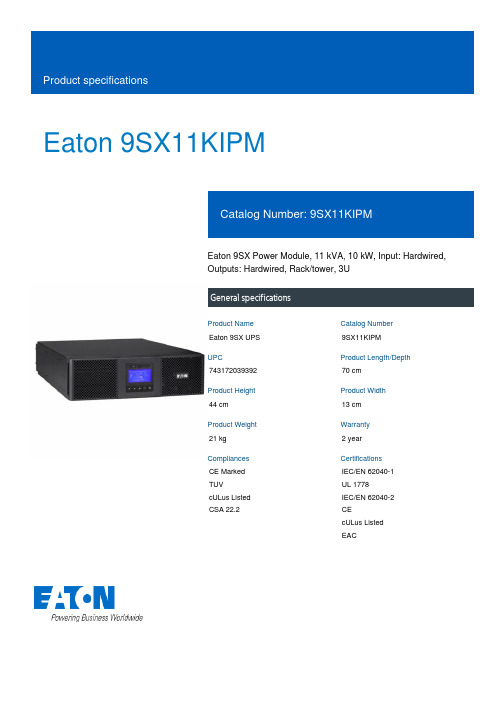
Eaton 9SX11KIPMEaton 9SX Power Module, 11 kVA, 10 kW, Input: Hardwired,Outputs: Hardwired, Rack/tower, 3UGeneral specificationsEaton 9SX UPS9SX11KIPM74317203939270 cm44 cm13 cm21 kg 2 yearCE Marked TUVcULus Listed CSA 22.2IEC/EN 62040-1 UL 1778IEC/EN 62040-2 CEcULus Listed EACProduct Name Catalog Number UPC Product Length/Depth Product Height Product Width Product Weight Warranty Compliances CertificationsView runtime graph No batteryYes Hardwired230V10 kW0.9200/208/220/230/240/250 V +/- 1%Sine wave230V default (200/208/220/230/240/250V) 21Online/Double-conversion11 kVAHardwired/fixed connection230V default (200/208/220/230/240/250V) 50/60 Hz>.99176-276 V (100-276 V with derating)NoRuntime graphBattery replacement Battery quantityBattery management Extended battery capability ReceptacleVoltageWattageOutput power factorOutput voltage rangeOutput waveformOutput nominal voltageVoltage distortion output (linear load) - max Feed typeTopologyVA ratingInput connection Input nominal voltage Nominal frequency Input power factor Input voltage range Includes network card CommunicationABM & Temperaturecompensated chargingmethod (user selectable)Automatic battery testDeep discharge protectionAutomatic recognition ofexternal battery unitsUSB port (HID compliant)Serial port (RS232)Mini terminal block forremote On/OffMini-terminal block forremote power offDry contacts (4 outputs,relay, DB9)40-70 HzNoMultilingual graphical LCD display YesOne slot for optional communication card Eaton Intelligent Power Manager, Eaton Intelligent Power Protector Other3000 m <50 dB at 1 meter 0° to 40°C (32° to 104°F)0-95% non-condensingFree standing model 1YesYes Black 95NoInput frequency range Ethernet interface User interfacePotential free switch contact Expansion slotsSoftware compatibilityType of interface Altitude Noise level Temperature range Relative humidity Construction type Package contents Phase (output)Internal bypass Auto shutdown function Color Efficiency Rack mounting kit Power Module USB cable Serial cable(2) Supports for tower mountingSafety instructions Quickstart guideEaton Corporation plc Eaton House30 Pembroke Road Dublin 4, Ireland © 2023 Eaton. All rights reserved. Eaton is a registered trademark.All other trademarks areproperty of their respective owners./socialmedia1NoEaton UPS Services Quick Guide 2021Eaton UPS and battery services EC DoC Eaton 9SX Eaton 9SX-9PX UPS - 8-11 kVA-EBM 240V - Installation and user manualEaton 9SX UPS - 5/6/8/11 kVA - DatasheetPhase (input)Hot swap power BrochuresCertification reports Manuals and user guidesTechnical data sheets。
PCS-9721C_X_说明书_国内中文_国内标准版_X_R1.00_(ZL_PWZD5204.1006)
南京南瑞继保电气有限公司
i
PCS-9721C 配网自动化终端
警告 !
曝露端子 在装置带电时不要触碰曝露的端子等 ,因为可能会产生危险的高电压 。
残余电压 在装置电源关闭后 ,直流回路中仍然可能存在危险的电压。这些电压需在数秒钟后才会消失。
警示 !
接地 装置的接地端子必须可靠接地。
运行环境 该装置只允许运行在技术参数所规定的大气环境中 ,而且运行环境不能存在不正常的震动。
2.1.1 交流遥测................................................................................................................... 5 2.1.2 遥信 .......................................................................................................................... 5 2.1.3 控制 .......................................................................................................................... 5 2.2 故障判断功能...................................................................................................................... 5 2.2.1 过流故障判断 ........................................................................................................... 5 2.2.2 过负荷判断 ............................................................................................................... 5 2.2.3 接地故障判断 ........................................................................................................... 5 2.3 数据处理 ............................................................................................................................. 6 2.3.1 实时测量数据 ........................................................................................................... 6 2.3.2 数据统计................................................................................................................... 6 2.4 告警及异常监测功能........................................................................................................... 7 2.4.1 线路运行异常告警 .................................................................................................... 7 2.4.2 装置自检异常 ........................................................................................................... 8 2.5 通讯功能 ............................................................................................................................. 8 2.5.1 智能装置接入 ........................................................................................................... 8 2.5.2 主从级联................................................................................................................... 8 2.5.3 定值上送和修改 ........................................................................................................ 8 2.5.4 故障信息上送 ........................................................................................................... 9 2.5.5 运行告警信息上送 .................................................................................................... 9 2.5.6 遥信变位信息上送 .................................................................................................... 9 2.5.7 遥测上送................................................................................................................... 9
in-win+925+用户手册说明书

使用者手册Version 1.0产品故事低调奢华 浑然天成925承袭928的美学魅力,淬炼出奢华的优雅并呈现在全塔式机壳中。
一体折弯的阳刚设计,在发丝与铝合金中交织出的精湛工艺,多样化的散热及空间配置的美学设计,先进的备战舞台,渾然天成。
规格* 本产品符合欧盟有害物质使用限制指引 (RoHS)* 产品规格视各销售区域略有不同机种产品型号颜色机壳型式材质主板相容适配卡扩展槽最高兼容性上置输出/入埠隐藏式磁盘槽散热系统兼容电源供应器兼容产品尺寸(高 x 宽 x 长)包装尺寸 (高 x 宽 x 长)净重毛重925IW-CS-925BLK 黑色高直立式机壳铝合金, 强化玻璃, ABS, SECC环保钢板12" x 13" E-ATX, ATX, Micro-ATX, Mini-ITX PCI-E x 8 Vertical PCI-E x 2支持高规格显卡长度: 420mm (Maximum)支援CPU散热器高度: 200mm 1 x USB 3.1 Gen 2 Type-C 2 x USB 3.0HD Audio 4 x 3.5"3 x 2.5"上 - 支援3 x 120mm风扇或360mm水冷排前 - 支援3 x 120mm风扇或2 x 140mm风扇 ;或360mm / 280mm 水冷排(当安装360mm水冷排时需移除2个3.5"盘架) 后 - 支援3 x 120mm风扇 PSII : ATX12V 可安装区域长度达140 ‒ 200mm 570 x 280 x 608mm 22.4" x 11" x 26.7"652 x 392 x 695mm25.6" x 15.4" x 27.3"17.8公斤, 39磅21公斤, 46磅包装内容1.925 机壳2.QR Code卡3.零件包User Manual 3RAMZF163100零件包a. 主板固定铜柱 x16b. 主板铜柱套筒 x1c. 六角头螺丝 x24d. 2.5"硬盘螺丝 x12e. 3.5"硬盘螺丝 x12f. 束线带 x10g. 水冷排垫片 x24h. 显卡支撑架 x 2i. 六角板手 x 1j. 擦拭布 x 1k. 主板扩充铜柱 x 2l. 主板扩充螺丝 x 2df e h k i jg l1. I/O面板1. 3.5"硬盘槽2. 2.5"硬盘槽3. 电源供应器安装区4. 上置风扇/水冷排安装区5. 后方风扇6. 前方风扇/水冷排安装区7. 主板安装区8. CPU散热器快速安装孔9. PCI-E(适配卡)扩展槽10. 直立式显卡扩展槽11. 显卡支撑架安装孔12. 风扇滤网13. 防震脚垫安装步骤请扫描QR Code或至以下网址观看影片教学: /embed/XNDQyMTA2NTE3Ng注意事项与保固范围■ 注意事项1. 请确实遵循本使用手册之指示进行安装!2. 安装计算机产品的过程中,请戴上静电环及手套进行安装,否则 可能会导致人员及机器的伤害与损坏。
埃尔克莱特电子有限公司产品说明书
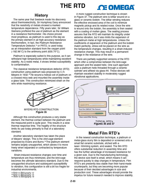
HistoryThe same year that Seebeck made his discovery about thermoelectricity, Sir Humphrey Davy announced that the resistivity of metals showed a marked temperature dependence. Fifty years later, Sir William Siemens proffered the use of platinum as the element in a resistance thermometer. His choice provedmost propitious, as platinum is used to this day asthe primary element in all high-accuracy resistance thermometers. In fact, the Platinum Resistance Temperature Detector,15 or PRTD, is used todayas an interpolation standard from the oxygen point (-182.96°C) to the antimony point (630.74°C).Platinum is especially suited to this purpose, as it can withstand high temperatures while maintaining excellent stability. As a noble metal, it shows limited susceptibility to contamination.The classical resistance temperature detector (RTD) construction using platinum was proposed by C.H. Meyers in 1932.12 He wound a helical coil of platinum on a crossed mica web and mounted the assembly inside a glass tube. This construction minimized strain on theAlthough this construction produces a very stable element, the thermal contact between the platinum and the measured point is quite poor. This results in a slow thermal response time. The fragility of the structure limits its use today primarily to that of a laboratorystandard.Another laboratory standard has taken the placeof Meyers’ design. This is the bird-cage element proposed by Evans and Burns.16The platinum element remains largely unsupported, which allows it to move freely when expanded or contracted by temperature variations.Strain-induced resistance changes over time and temperature are thus minimized, and the bird-cage becomes the ultimate laboratory standard. Due to the unsupported structure and subsequent susceptibility to vibration, this configuration is still a bit too fragile for industrial environments.Metal Film RTD’sIn the newest construction technique, a platinum or metal-glass slurry film is deposited or screened onto a small flat ceramic substrate, etched with alaser- trimming system, and sealed. The film RTD offers substantial reduction in assembly time andhas the further advantage of increased resistance for a given size. Due to the manufacturing technology, the device size itself is small, which means it can respond quickly to step changes in temperature. Film RTD’s are presently less stable than their hand-made counterparts, but they are becoming more popular because of their decided advantages in size and production cost. These advantages should provide the impetus for future research needed to improve stability.THE RTD12Refer to Bibliography 12 15Refer to Bibliography 15 16 Refer to Bibliography 16A more rugged construction technique is shownin Figure 37. The platinum wire is bifilar wound on aglass or ceramic bobbin. The bifilar winding reducesthe effective enclosed area of the coil to minimizemagnetic pickup and its related noise. Once the wireis wound onto the bobbin, the assembly is then sealed with a coating of molten glass. The sealing processassures that the RTD will maintain its integrity underextreme vibration, but it also limits the expansion ofthe platinum metal at high temperatures. Unless thecoefficients of expansion of the platinum and the bobbin match perfectly, stress will be placed on the wire asthe temperature changes, resulting in a strain-induced resistance change. This may result in a permanentchange in the resistance of the wire.There are partially supported versions of the RTDwhich offer a compromise between the bird-cageapproach and the sealed helix. One such approachuses a platinum helix threaded through a ceramiccylinder and affixed via glass-frit. These devices willmaintain excellent stability in moderately ruggedvibrational applications.Glass sealed Biflar WindingThick Film OMEGA Film ElementTypical RTD ProbesThin Film OMEGA TFD ElementZ-33Z-34Metals - All metals produce a positive change in resistance for a positive change in temperature. This, of course, is the main function of an RTD. As we shall soon see, system error is minimized when the nominal value of the RTD resistance is large. This implies a metal wire with a high resistivity. The lower theresistivity of the metal, the more material we will have to use.Table 6 lists the resistivities of common RTD materials.METAL RESISTIVITY OHM/CMF (cmf = circular mil foot) _________ ___________________Gold Au 13.00 Silver Ag 8.8 Copper Cu 9.26 Platinum Pt 59.00 Tungsten w 30.00Nickel Ni36.00Table 6Because of their lower resistivities, gold and silver are rarely used as RTD elements. Tungsten has a relatively high resistivity, but is reserved for very high temperature applications because it is extremely brittle and difficult to work.Copper is used occasionally as an RTD element. Its low resistivity forces the element to be longer than a platinum element, but its linearity and very low cost make it an economical alternative. Its upper temperature limit is only about 120˚C.The most common RTD’s are made of eitherplatinum, nickel, or nickel alloys. The economical nickel derivative wires are used over a limited temperature range. They are quite non-linear and tend to drift with time. For measurement integrity, platinum is the obvious choice.Resistance MeasurementThe common values of resistance for a platinum RTD range from 10 ohms for the bird-cage model to several thousand ohms for the film RTD. The single most common value is 100 ohms at 0°C. The DIN 43760 standard temperature coefficient of platinum wire is α = 0.00385. For a 100 ohm wire, this corresponds to + 0.385 ohms/°C at 0°C. This value for α is actually the average slope from 0°C to 100°C. The more chemically pure platinum wire used in platinum resistance standards has an α of +0.00392 ohms/ohm/°C. Both the slope and the absolute value are small numbers, especially when we consider the fact that the measurement wires leading to the sensor mayimpedance can contribute a significant error to our temperature measurement.A ten ohm lead impedance implies 10/0.385 ≅ 26°C error in measurement. Even the temperature coefficient of the lead wire can contribute a measurable error. The classical method of avoiding this problem has been theThe bridge output voltage is an indirect indication of the RTD resistance. The bridge requires four connection wires, an external source, and threeresistors that have a zero temperature coefficient. To avoid subjecting the three bridge-completion resistors to the same temperature as the RTD, the RTD isseparated from the bridge by a pair of extension wires:These extension wires recreate the problem that we had initially: The impedance of the extension wires affects the temperature reading. This effect can be minimized by using a three-wire bridge configuration:If wires A and B are perfectly matched in length, their impedance effects will cancel because each is in an opposite leg of the bridge. The third wire, C, acts as a sense lead and carries no current.The Wheatstone bridge shown in Figure 41 createsa non-linear relationship between resistance change and bridge output voltage change. This compounds the already non-linear temperature-resistance characteristic of the RTD by requiring an additional equation to convert bridge output voltage to equivalent RTD impedance.Figure 38Z-354-Wire Ohms - The technique of using a current source along with a remotely sensed digital voltmeter alleviates many problems associated with thebridge. The output voltage read by the dvm is directly proportional to RTD resistance, so only one conversion equation is necessary. The three bridge-completion resistors are replaced by one reference resistor. The digital voltmeter measures only the voltage droppedacross the RTD and is insensitive to the length of the lead wires.The one disadvantage of using 4-wire ohms is that weThis is a small price to pay if we are at all concernedwith the accuracy of the temperature measurement.3-Wire Bridge Measurement Errors If we know V S and V O , we can find R g and then solve for temperature. The unbalance voltage V o of a bridge builtwith R 1 = R 2 is: R 3 1V O = VS ——— – V S — (R 3 + R g) (2) If R g = R 3, V O = 0 and the bridge is balanced. This canbe done manually, but if we don’t want to do a manual bridge balance, we can just solve for R g in terms of V O : V S - 2V O Rg = R 3 ————(V S + 2V O)This expression assumes the lead resistance is zero. If R g is located some distance from the bridge in a3-wire configuration, the lead resistance R L will appearResistance to TemperatureConversionThe RTD is a more linear device than thethermocouple, but it still requires curve-fitting. TheCallendar-Van Dusen equation has been used for yearsto approximate the RTD curve:11, 13T T T TR T =R 0+R 0 α T-δ —— -1 —— -δ —— -1 ——[ (100 ) (100)(100 ) (100)3 ]Where:R T = Resistance at Temperature TR o = Resistance at T = 0˚Cα = Temperature coefficient at T = 0˚C (typically +0.00392Ω/Ω/˚C)δ = 1.49 (typical value for .00392 platinum) δ = 0 T > 00. 11 (typical) T < 0The exact values for coefficients α , δ , and δ aredetermined by testing the RTD at four temperatures and solving the resultant equations. This familiar equation was replaced in 1968 by a 20th order polynomial in order to provide a more accurate curve fit.The plot of this equation shows the RTD to be a more linear device than the thermocouple:11, 13Refer to Bibliography 11 and 13.in series with both R g and R 3: Again we solve for R g :V s - 2V o 4V oR g = R 3 ———— - R L ———— (V S + 2V o ) (Vs + 2V o)The error term will be small if V o is small, i.e., thebridge is close to balance. This circuit works well with devices like strain gauges, which change resistance value by only a few percent, but an RTD changes resistance dramatically with temperature. Assume theRTD resistance is 200 ohms and the bridge is designedfor 100 ohms:Since we don’t know the value of R L , we must use equation (a), so we get:6 - 1.9868R g = 100 ————— = 199.01 ohms (6 + 1.9868)The correct answer is of course 200 ohms. That’s aDVM。
NAS925系列变压器保护装置说明书V341

10.1. 适用范围 ................................................................ 29 10.2. 保护配置 ................................................................ 29 10.3. 测控配置 ................................................................ 29 10.4. 装置特点 ................................................................ 29 10.5. 应用说明 ................................................................ 30 降压变 110kV 侧后备保护 ...................................................... 30 升压变 110kV 侧后备保护 ...................................................... 30 10.6. 保护定值 ................................................................ 31 10.7. 典型接线示意图 .......................................................... 33 11. NAS925L 型变压器后备保护装置 ............................................... 34
11.1. 适用范围 ................................................................ 34 11.2. 保护配置 ................................................................ 34 11.3. 测控配置 ................................................................ 34 11.4. 装置特点 ................................................................ 34 11.5. 应用说明 ................................................................ 35 降压变中压侧或低压侧后备保护 ................................................ 35 升压变低压侧后备保护 ........................................................ 35 升压变中压侧后备保护 ........................................................ 36 11.6. 保护定值 ................................................................ 36 11.7. 典型接线示意图 .......................................................... 38 12. 13. 应 用 要 点 ................................................................. 39 辅助功能 .................................................................. 40 人机对话 ................................................................ 40 故障录波 ................................................................ 40 顺序事件记录 ............................................................ 41 开关变位记录 ............................................................ 41 矢量图显示 .............................................................. 41 DRS 软件的支持 ........................................................... 42
埃尔克斯电子产品的五种型号功能规范说明书

SPECIFICATIONS13Models 7520DT, 7530DT, 7540DT, 7550DT and 7564SAFunctional SpecificationsINPUTVoltage 115/230 VAC 15, Single Phase, User selection Frequency 50/60 Hz 5Fuse6.3 Amp 250V Slo-Blo for 7550DT and 7564SA 5 Amp 250V Slo-Blo for 75/20/30/40DTDIELECTRIC WITHSTAND TEST MODEOutput Rating5 KV @ 40 mA for 7550DT and 7564SA, 5 KV @ 20mA for 75/20/30/40DT6 KV @ 10 mA DC for 75/30/40/50DT and 7564SAOutput AdjustmentRange:0 - 5 KV AC 0 - 6 KV DCResolution: 1 volt/step Accuracy:(2 of setting 5 volts) Ramp-HI 12mA peak maximum, ON/OFF selectableCharge-LORange:0.0 - 350.0A DC or Auto setHI-Limit AC Range:0.00 - 40.00 mA for 7550DT and 7564SA, 0.00 - 20.00 mA for 75/20/30/40DT Resolution: 0.01 mA/step Accuracy: (2 of setting 2 counts) DC Range:0 - 9999AResolution: 1A/stepAccuracy:(2 of setting 2 counts) LO-Limit AC Range:0.000 - 9.999 mA Resolution: 0.001 mA/stepAccuracy: (2 of setting 2 counts) DC Range:0.0 - 999.9 AResolution: 0.1A/stepAccuracy:(2 of setting 2 counts) Arc Detection Range:1 - 9Failure DetectorAudible and VisualRecycledEquipment(410)email:***************************1981SPECIFICATIONS14Voltage Display Range: 0.00 - 6.00 KV Full Scale0.00 - 5.00 KV Full Scale for 7520DT onlyResolution: 10 volt/stepAccuracy: (2 of reading 2 counts)Current Display Auto RangeAC Range 1: 0.000mA - 3.500mAResolution: 0.001mA/stepRange 2: 3.00 - 40.00 mA for 7550DT and 7564SA,3.00 - 20.00 mA for 75/20/30/40DTResolution: 0.01 mA/stepDC Range 1: 0.0 A - 350.0 AResolution: 0.1A/stepRange 2: 300 A - 3500 AResolution: 1A/stepRange 3: 3000 A - 9990 AResolution: 10A/stepAccuracy: All Ranges (2 of reading 2 counts)DC Output Ripple 4**********************,ResistiveLoad Discharge Time 200 msMaximum CapacitiveLoad DC Mode1uF < 1KV0.75uF < 2KV0.5uF < 3KV0.08uF < 4KV0.04uF < 5KV0.01uF < 6KVAC Output Wave Form Sine Wave, Crest Factor = 1.3 - 1.5Output Frequency Range: 60 or 50 Hz, User SelectionAccuracy: 1%Output Regulation (1 of setting 5 volts) from no load to full load Dwell Timer Range: 0, 0.3 - 999.9 sec (0 = Constant)Resolution: 0.1 sec incrementsAccuracy: (0.1% + 0.05 sec)Ramp Timer Range: AC 0.1 - 999.9 secDC 0.4 - 999.9 secResolution: 0.1 sec incrementsAccuracy: (0.1% + 0.05 sec)RecycledEquipment(410)email:***************************SPECIFICATIONS15Ground Continuity For 75/20/30/40/50DT Current : DC 0.1 A 0.01A, fixedMax. ground resistance : 1 0.1, fixed Ground Fault Interrupt GFI Trip Current: HV Shut Down Speed: 450 A max (AC or DC)< 1msINSULATION RESISTANCE TEST MODE Model 75/30/40/50DT, 7564SAOutput VoltageRange:100 - 1000 Volts DC Resolution: 1 volt/step Accuracy:(2 of reading 2 volts) Short Circuit Current Maximum: 12mA peak Voltage DisplayRange: 0 - 1000 VResolution: 1 volt/stepAccuracy:(2 of reading 2 counts) Resistance DisplayRange: 1 - 9999 M (4 Digit, Auto Ranging)Resolution:500VDC 1000VDC M M M 0.001 1.000 - 5.388 1.000 - 9.999 0.01 1.40 - 53.88 2.80 - 99.99 0.1 14.0 - 538.8 28.0 - 999.9 1104 - 9999280 - 9999Accuracy:(2 of reading 2 counts) at test voltage 500 - 1000V and 1 - 1000 M(8 of reading 2 counts) at test voltage 500 - 1000V and 1000 - 9999 M(8 of reading 2 counts) at test voltage 100 - 500V and 0 - 1000 MCharge-LO Range: 0.000 - 3.500A or Auto Set HI-Limit Range: 0 - 9999 M (0 = Off) LO-Limit Range: 1 - 9999 MDelay TimerRange: 0, 0.5 - 999.9 sec (0 = Constant) Resolution: 0.1 sec/stepAccuracy:(0.1% + 0.05 sec)Ground Fault InterruptGFI Trip Current:HV Shut Down Speed:450 A max (AC or DC) < 1msRecycledEquipment(410)email:***************************SPECIFICATIONS16GROUND BOND TEST MODE Model 7564SA onlyOutput Voltage Range: 3.00 - 8.00 Volts AC (Open Circuit Limit) Resolution: 0.01 volt/stepAccuracy: (2 % of Setting + 0.03V ) O.C. Condition Output Frequency Range: 60 or 50 Hz, User Selection Accuracy: 1%Output CurrentRange: 3.00 - 30.00 Amps AC Resolution: 0.01 Amp/stepAccuracy :(2 % of Setting + 0.02 A) Current DisplayRange: 0.00 - 30.00 Amps Resolution: 0.01 Amp/stepAccuracy:(3 % of Reading + 0.03 A) Resistance DisplayRange: 0 - 600 m Resolution: 1 m /stepAccuracy:(2 % of Reading + 2 m ) HI-LimitRange: 0 - 600 m for 3 - 10 A 0 - 150 m for 3 - 30 A Resolution: 1 m /stepAccuracy:(2 % of Setting + 2 m ) LO-LimitRange: 0 - 600 m for 3 - 10 A 0 - 150 m for 3 - 30 A Resolution: 1 m /stepAccuracy:(2 % of Setting + 2 m ) Dwell TimerRange: 0, 0.5 - 999.9 sec (0 = Constant) Resolution: 0.1 sec/step Accuracy:(0.1% + 0.05 sec)Milliohm OffsetMax. Offset Capability: 200 mResolution: 1 m / stepAccuracy:(2 % of Setting + 2 m )RecycledEquipment(410)email:***************************SPECIFICATIONS17GENERAL SPECIFICATIONSPLC Remote Control Input - Test, Reset, Recall memory 1, 2 and 3Output - Pass, Fail, Test-in-ProcessMemory Allows storage of up to 50 groups different test programsand 8 step/each memory. Step is not available on 7520DT SecurityProgrammable password lockout capability to avoid unauthorized access to test set-up program. LCD Contrast Setting 9 ranges set by the numeric keys on the front panel. Buzzer Volume Setting 10 ranges set by the numeric key on the front panel.Calibration Software and adjustments are made through front panel. Mechanical Bench or rack mount with tilt up front feet. Dimension7540DT, 7550DT and 7564SA:(W x H x D) 17 x 5.8 x 20.3 in. (432 x 147 x 515 mm) 7520DT and 7530DT:(W x H x D) 17 x 5.8 x 12 in. (432 x 147 x 305 mm)Weight7564SA without scanner 52.5 lbs (24 Kgs) 7564SA with built-in scanner 57.0 lbs (26 Kgs) 7550DT without scanner 50.5 lbs (23 Kgs) 7550DT with built-in scanner 55.0 lbs(25 Kgs) 7540DT with 4 port scanner 39.6 lbs (18 Kgs) 7540DT with 8 port scanner41.8 lbs(19 Kgs) 7530DT scanner not available 24.8 lbs (11.27 Kgs) 7520DT scanner not available 24.8 lbs(11.27 Kgs)Scanner Port Two Port Maximum including the built-in scanner. Not available on 7520DT, 7530DT and 7540DT.Scanner Built-in OptionHigh Voltage x 4 Ports (7540DT only)High Voltage x 8 Ports (75/40/50DT and 7564SA) Ground Bond x 8 Ports (7564SA only)RecycledEquipment(410)email:***************************。
AXIS V5925 PTZ 高清摄像头说明书
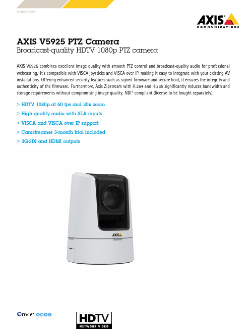
AXIS V5925PTZ CameraBroadcast-quality HDTV 1080p PTZ cameraAXIS V5925combines excellent image quality with smooth PTZ control and broadcast-quality audio for professional webcasting.It’s compatible with VISCA joysticks and VISCA over IP,making it easy to integrate with your existing AV installations.Offering enhanced security features such as signed firmware and secure boot,it ensures the integrity and authenticity of the firmware.Furthermore,Axis Zipstream with H.264and H.265significantly reduces bandwidth and storage requirements without compromising image quality.NDI ®compliant (license to be bought separately).>HDTV 1080p at 60fps and 30x zoom >High-quality audio with XLR inputs >VISCA and VISCA over IP support >Camstreamer 3-month trial included >3G-SDI and HDMIoutputsDatasheetAXIS V5925PTZ Camera CameraImage sensor Progressive scan RGB CMOS1/2.8"Lens 4.4–132mm,F1.4-4.6Horizontal field of view:62°–2.3°Vertical field of view:37°–1.3°Autofocus,P-iris controlDay and night Automatically removable infrared-cut filterMinimum illumination Color:1.0lux at30IRE F1.4 B/W:0.03lux at30IRE F1.4Shutter speed1/10000s to1sPan/Tilt/Zoom Pan:±170°,0.2-100°/sTilt:-20°-90°,0.2-90°/sZoom:30x Optical,12x Digital,Total360x256presets positions,Control queue,On-screen directionalindicator,Adjustable zoom speed,PTZ response profiles System on chip(SoC)Model ARTPEC-7Memory1GB RAM,512MB FlashVideoVideo compression H.264(MPEG-4Part10/AVC)Baseline,Main and High Profiles H.265(MPEG-H Part2/HEVC)Main ProfileMotion JPEGResolution1920x1080HDTV1080p to160x90HDMI/SDI Output:1080p@50/60fps(50/60Hz)Frame rate Up to60/50fps(60/50Hz)in all resolutionsVideo streaming Multiple,individually configurable streams in H.264,H.265and Motion JPEGAxis Zipstream technology in H.264and H.265Controllable frame rate and bandwidthVBR/ABR/MBR H.264/H.265HDMIHD-SDI:SMPTE2923G-SDI:SMPTE424,SMPTE425(3G-SDI mapping supportsLevel A/Level B dual link mapping)Image settings Saturation,brightness,sharpness,white balance,day/nightthreshold,exposure mode,exposure zones,defogging,rotation:0°,180°AudioAudio streaming Two-way,stereoHD-SDI:SMPTE ST299-13G-SDI:SMPTE ST299-2Audio encoding SDI:AES324bit,48kHzHDMI:LPCMNetwork:AAC LC8/16/32/44.1/48kHz,G.711PCM8kHz,G.726ADPCM8kHz,Opus8/16/48kHz,LPCM48kHz,Configurable bit rateXLR input2balanced inputs(left/right)Microphone phantom power48VBalanced external microphoneBalanced line levelLine input impedance:>10kOhmMaximum input level:4.4VrmsBandwidth:20Hz-20kHz(±3dB),may be limited by samplerateTHD+N:<0.03%Signal-to-Noise ratio:>85dB@0dB gain,>78dB@30dB gain3.5mm input Microphone Power5V via2.2kOhmUnbalanced external microphoneUnbalanced lineLine input impedance:>10kOhmMaximum input level:2.2VrmsBandwidth:20Hz-20kHz(±3dB),may be limited by samplerateTHD+N:<0.03%Signal-to-Noise ratio:>87dB@0dB gain,>83dB@30dB gain3.5mm output 3.5mm unbalanced stereo outputOutput impedance:<100Ohm,short circuit proofMaximum output level:>0.707VrmsBandwidth:20Hz-20kHz(±3dB),may be limited by samplerateTHD+N:<0.03%@10kOhm loadSignal-to-Noise ratio:>87dBSDI output Bandwidth:20Hz-20kHz(±3dB)THD+N:<0.03%Signal-to-Noise ratio:>87dBHDMI output Bandwidth:20Hz-20kHz(±3dB)THD+N:<0.03%Signal-to-Noise ratio:>87dBNetworkSecurity IP address filtering,HTTPS a encryption,IEEE802.1x(EAP-TLS)anetwork access control,user access log,centralized certificatemanagementNetworkprotocolsIPv4/v6,ICMPv4/ICMPv6,HTTP,HTTP/2,HTTPS a,TLS a,QoS Layer3DiffServ,FTP,CIFS/SMB,SMTP,mDNS(Bonjour),UPnP TM,SNMPv1/v2c/v3(MIB-II),DNS/DNSv6,DDNS,NTP,NTS,RTSP,RTP,SFTP,TCP,UDP,IGMPv1/v2/v3,RTCP,ICMP,DHCPv4/v6,ARP,SSH,SIP,LLDP,CDP,MQTT,Syslog,Link-Local address(ZeroConf),HDMI,3G-SDI,VISCASystem integrationApplicationProgrammingInterfaceOpen API for software integration,including VAPIX®andAXIS Camera Application Platform;specifications at One-click cloud connectionONVIF®Profile G,ONVIF®Profile M,ONVIF®Profile S,ONVIF®Profile T,specification at Support for Session Initiation Protocol(SIP)for integration withVoice over IP(VoIP)systems,peer to peer or integrated withSIP/PBX.Event conditions Analytics,external input,edge storage events,virtual inputsthrough APIAudio:audio detectionCall:state,state changeDevice status:above operating temperature,above or belowoperating temperature,below operating temperature,fan failure,IP address removed,network lost,new IP address,storage failure,system ready,within operating temperatureEdge storage:recording ongoing,storage disruptionI/O:digital input,manual trigger,virtual inputMQTT subscribePTZ:PTZ malfunctioning,PTZ movement,PTZ preset positionreached,PTZ readyScheduled and recurring:scheduled eventVideo:average bitrate degradation,live stream openEvent actions MQTT publishRecord video:SD card and network shareUpload of images or video clips:FTP,SFTP,HTTP,HTTPS,networkshare and emailPre-and post-alarm video or image buffering for recording oruploadNotification:email,HTTP,HTTPS,TCP and SNMP trapPTZ:PTZ presetOverlay text,external output activation,play audio clip,zoompreset,day/night mode,make callData streaming Event dataBuilt-ininstallation aidsPixel counter,leveling guideAnalyticsApplications IncludedAXIS Video Motion Detection,AXIS PTZ AutotrackingSupport for AXIS Camera Application Platform enablinginstallation of third-party applications,see /acap CybersecurityEdge security Software:Signed firmware,brute force delay protection,digest authentication,password protection,AES-XTS-Plain64256bitSD card encryptionHardware:Secure bootNetwork security IEEE802.1X(EAP-TLS)a,HTTPS/HSTS a,TLS v1.2/v1.3a,NetworkTime Security(NTS),X.509Certificate PKI,IP address filteringDocumentation AXIS OS Hardening GuideAxis Vulnerability Management PolicyAxis Security Development ModelAXIS OS Software Bill of Material(SBOM)To download documents,go to /support/cybersecu-rity/resourcesTo read more about Axis cybersecurity support,go to/cybersecurityGeneralCasing ASA plastic coverColor:White NCS S1002-BPower11–13V DC(12V power supply included),typical14W,max25W Connectors RJ4510BASE-T/100BASE-TXTerminal block for2configurable alarm input/output3.5mm stereo mic/line in,3.5mm stereo line outXLR-3(left+right)mic/line in(with48V phantom power)HDMI Type A,BNC for SDIDC inputRS232serial connector for VISCAStorage Support for microSD/microSDHC/microSDXC cardSupport for SD card encryption(AES-XTS-Plain64256bit)Recording to network-attached storage(NAS)For SD card and NAS recommendations see Operating conditions 0°C to40°C(32°F to104°F) Humidity10-85%RH(non-condensing)Storage conditions -40°C to65°C(-40°F to149°F)Humidity5-95%RH(non-condensing)Approvals EMCEN55032Class A,EN55035,EN61000-3-2,EN61000-3-3,EN61000-6-1,EN61000-6-2,FCC Part15Subpart B Class A,ICES-3(A)/NMB-3(A),VCCI Class A,RCM AS/NZS CISPR32Class A,KC KN32Class A,KC KN35SafetyIEC/EN/UL62368-1,CAN/CSA C22.2No.62368-1,KC-Mark,IS13252EnvironmentIEC60068-2-1,IEC60068-2-2,IEC60068-2-6,IEC60068-2-14,IEC60068-2-27,IEC60068-2-78NetworkNIST SP500-267Dimensions Height:180mm(7.1in)ø136mm(5.4in)Weight 1.5kg(3.3lb)IncludedaccessoriesPower supply,wall/ceiling mount,terminal connector for I/O,installation guide,Windows®decoder user license,Camstreamer3-month trialOptionalaccessoriesAXIS T8310Video Surveillance Control BoardAXIS VISCA CableFor more accessories,see Languages English,German,French,Spanish,Italian,Russian,SimplifiedChinese,Japanese,Korean,Portuguese,Traditional ChineseWarranty5-year warranty,see /warrantya.This product includes software developed by the OpenSSL Project for use in theOpenSSL Toolkit.(),and cryptographic software written by Eric Young(*****************).©2020-2023Axis Communications AB.AXIS COMMUNICATIONS,AXIS,ARTPEC and VAPIX are registered trademarks ofAxis AB in various jurisdictions.All other trademarks are the property of their respective owners.We reserve the right tointroduce modifications without notice.T10155563/EN/M15.2/2302。
费希尔久安产品维护手册

费希尔久安产品维护手册(总55页)-CAL-FENGHAI.-(YICAI)-Company One1-CAL-本页仅作为文档封面,使用请直接删除1目录一、调压装置51.51.1功能.......................................................... (5)1.1.1.基本功能........................................................ (5)1.1.2.可扩展功能........................................................ (5)1.2配置.......................................................... (5)1.2.1.基本配置........................................................ (5)1.2.2.标准调压柜流程图........................................................ (6)1.3运行状况显示方式............................................................ (6)1.4操作方式............................................................ (6)1.5分类.......................................................... (6)2. 安装 (7)3. 使用 (7)3.1 使用注意事项 (7)3.2 气密性检查 (8)3.3 设定值检查 (9)3.3.1. 调压器出口压力设定值检查 (9)3.3.2. 切断阀启动压力设定值检查 (9)3.3.3. 放散阀启动压力设定值检查 (10)3.4 启用 (10)3.5 工作管路与备用管路的压力设定和切换方法 (10)3.5.1 压力设定 (10)3.5.2 切换方法 (11)4. 维护维修11 4.1 维护通则 (11)4.2 首检 (11)4.3 巡检 (11)4.4 定期检查 (12)4.5 定期维修 (12)4.6 故障维修 (12)二、调压器 (13)1. RTZ-50FQ 调压器 ..............................................................................................................131.1 简介 (13)1.1.1. 用途 (13)1.1.2. 技术特性 (13)1.1.3. 结构特征 (13)1.1.4. 工作原理 (14)1.1.5. 主要结构尺寸 (14)1.2 安装 (15)1.3 使用 (15)1.3.1. 总则 (15)1.3.2. 启用 (15)1.3.3. 出口压力设定 (16)1.3.5. 切断器启动压力设定 (16)1.3.6. 切断器的复位操作 (16)1.4 维护 (16)1.4.1. 日常维护 (16)1.4.2. 定期检查 (16)1.4.3. 维修 (17)1.5 常见故障及处理方法 (19)2. RTZ-SN 系列调压器 ..........................................................................................................20 2.1 简介 (20)2.1.1 用途 (20)2.1.2 技术特性 (20)2.1.3 结构特征 (20)2.1.4 工作原理 (21)2.1.5 主要安装尺寸 (21)2.2 安装 (22)2.3 使用 (22)2.3.1. 总则 (22)2.3.2. 启用 (22)2.3.3. 出口压力设定 (23)2.3.4. 关闭压力检查 (23)2.4 维护 (23)2.4.1 日常维护 (23)2.4.2 定期检查 (23)2.4.3 维修 (23)2.5 常见故障及处理方法 (25)3. RTZ-SP 系列调压器...........................................................................................................26 3.1 简介 (26)3.1.1 用途 (26)3.1.2 技术特性 (26)3.1.3 结构特征 (26)3.1.4 工作原理 (27)3.1.5 主要结构尺寸 (27)3.2 安装 (28)3.3 使用 (28)3.3.1. 总则 (28)3.3.2. 启用 (28)3.3.3. 出口压力设定 (29)3.3.4. 关闭压力检查 (29)3.3.5. 切断启动压力设定 (29)3.3.6. 切断阀复位操作 (29)3.4 维护 (30)3.4.1. 日常维护 (30)3.4.2. 定期检查 (30)3.5 常见故障及处理方法 (34)4. RTJ-NH 系列调压器 ..........................................................................................................35 4.1 简介 (35)4.1.1. 用途 (35)4.1.2. 技术特性 (35)4.1.3. 结构特征 (35)4.1.4. 工作原理 (36)4.1.5. 主要结构尺寸 (36)4.2 安装 (37)4.3 使用 (37)4.3.1. 总则 (37)4.3.2. 启用 (37)4.3.3. 出口压力设定 (38)4.3.4. 关闭压力检查 (38)4.4 维护维修 (38)4.4.1. 日常维护 (38)4.4.2. 定期检查 (38)4.4.3. 维修 (38)4.5 常见故障及处理方法 (43)5. RTZ-Q 系列调压箱...............................................................................................................44 5.1 简介 (44)5.1.1. 用途 (44)5.1.2. 技术特性 (44)5.1.3. 结构特征 (44)5.1.4. 工作原理 (45)5.1.5. 主要结构尺寸 (45)5.2 安装 (46)5.3 使用 (46)5.3.1. 总则 (46)5.3.2. 启用 (46)5.3.3. 出口压力设定 (46)5.3.4. 关闭压力检查 (46)5.3.5. 切断器启动压力设定 (46)5.3.6. 切断器复位操作 (46)5.4 维护维修 (47)5.4.1. 日常维护 (47)5.4.2. 定期检查 (47)5.4.3. 维修 (47)5.5 常见故障及处理方法 (48)6. AQZ 切断阀........................................................................ ....... ....... ....... ......4 96.1 简介 (49)6.1.1. 用途 (49)6.1.2. 技术特性 (49)6.1.3. 结构特征 (49)6.1.4. 工作原理 (49)6.1.5. 主要结构尺寸 (50)6.2 安装 (50)6.3 使用 (51)6.3.1. 总则 (51)6.3.2. 启用 (51)6.3.3. 启动压力设定 (51)6.3.4. 启动压力检查 (51)6.3.5. 复位操作 (52)6.4 维护维修 (52)6.4.1. 日常维护 (52)6.4.2. 定期检查 (52)6.4.3. 维修 (52)6.5 常见故障及处理方法 (54)本手册主要描述了Fisher-Jeon公司生产的调压装置及主要设备的结构、工作原理和安装、使用、维护维修及常见故障的处理方法。
【仪器说明书】5E-CHN2000元素分析仪使用说明书
5E-CHN2000 使用说明书
1 介绍 ............................................................................................................................................... 3 2 安装 ............................................................................................................................................. 10
仪器安装................................................................................................................................. 10 电源安装................................................................................................................................. 12 环境要求................................................................................................................................. 14 坩埚的安装............................................................................................................................. 15 净化管的安装......................................................................................................................... 17 数据通讯的安装..................................................................................................................... 18 3 可选项的安装 ............................................................................................................................. 19 天平的安装............................................................................................................................. 20 打印机的安装......................................................................................................................... 22 4 系统设置 .................................................................................................................................... 23 图例操作面板控制和功能..................................................................................................... 23 电源供应................................................................................................................................. 25 主界面浏览.................. 26
艾顿绿色电气液氢产品介绍说明书

XIRIAAutomotiveAerospaceElectricalTruckHydraulicsAutomotive Aerospace Electrical Truck Hydraulics Poweringbusiness worldwideEaton delivers the power inside hundreds of products that are answering the demands of today’s fast changing world. We help our customers worldwide manage the power they need for buildings, aircraft, trucks, cars, machinery and entire businesses. And we do it in a way that consumes fewer resources.Next generationtransportationEaton is driving the development of newtechnologies – from hybriddrivetrains and emission control systems to advanced engine components – that reduce fuel consumption and emissions in trucks and cars. Higher expectationsWe continue to expand our aerospace solutions andservices to meet the needs of new aviation platforms,including the high-flying light jet and very light jet markets. Building on our strengths Our hydraulics businesscombines localised service and support with an innovative portfolio of fluid powersolutions to answer the needs of global infrastructure projects, including locks, canals and dams.Powering Greener Buildings and BusinessesEaton’s Electrical Group is a leading provider of powerquality, distribution and control solutions that increase energy efficiency and improve power quality, safety and reliability. Our solutions offer a growing portfolio of “green” products and services, such as energy audits and real-time energy consumption monitoring.Eaton’s Uninterruptible Power Supplies (UPS), variable-speed drives and lighting controls help conserve energy and increase efficiency.1Eaton’s range ofSF6free switchgear for Medium Voltage Eaton Corporation is a worldwide leader in the design, manufacture, and sale of safe, reliableand high-performance medium voltage power distribution equipment in accordance with IEC,ANSI and GB / DL standardsComplete Global Medium Voltage Switchgear Solutions Eaton, a premier leader in designing and manufacturing power distribution and protection equipment in the electrical industry, offers a comprehensive range of medium voltage (MV) solutions to meet the needs of virtually every application. From products that feature cutting-edge design that allow for easy access, maintenance and space savings, to arc-resistant products that enhance safety, Eaton’s medium voltage solutions provide a variety of products for every need. Additionally, Eaton’s global service network provides maximum customer support in all regions of the world.As one of the few completely vertically integrated and diversified industrial manufacturers in the world, Eaton designs not only MV assemblies, but also the key components that comprise the MV solutions – from steel housing and circuit breaker compartments to vacuum interrupters, circuit breakers, bus systems and fuses. Eaton’s MV heritage, strengthened by acquisitions such as Westinghouse DCBU, Cutler Hammer, MEM and Holec, has resulted in breakthrough MV technologies and numerous international patents over the years.Part of Eaton’s complete electrical PowerChain Solutions–which help businesses minimize risks while realizing greater reliability, cost efficiencies, capital utilization and safety – Eaton’s medium voltage equipment meets all applicable standards and certifications such as IEC, NEMA / ANSI, GB / DL, UL, IEEE, KEMA and CSA.When it comes to medium voltage solutions, you can trust theone name with a long history of proven performance: Eaton.XIRIA green gas insulated RMUProduct FeatureGreen, Smart, Compact solution: XIRIA XIRIA is Eaton’s new generation of environmental-friendly type green gas insulated Ring Main units.They are characterized by their high level of operational safety and applicable for 12kV power distribution system.XIRIA units are also very compact and can provide modular single anel and combination block panel.Both the primary and mechanical parts are housed in a fully sealed stainless steel tank with 0.02Mpa dry air which effectively protects the system against environmental influences.Two basic function versions in our product range:a vacuum load break switch for ring cable connectionsa vacuum circuit breaker for protecting transformers and cableconnections.Both versions can be supplied in a unit in any desired combination and order.XIRIA is a well designed environmental-friendly Ring Main Units. For example, when developing the system we intentionally opted for protection in the form of a circuit breakercombined with an electronic relay. This is a modern, safe andflexible alternative to fuse protection.In addition it also makes Xiria very easy to use in an automated distribution network. These specific features make Xiria aneasy-to-use system that responds perfectly to changing electricity distribution requirements, both now and in the future. Green and cleanXiria is made exclusively of environmentally-friendlymaterials. The insulation medium is clean, dry airand the switching medium is vacuum. Thus Xiriaresponds to the demand for sustainability in energydistribution. The unit is easy to dismantle at the endof its service life as the materials used are clearlylabelled and can be reused. This facilitates recyclingand avoids excessive costs and environmentaltaxes when the unit is decommissioned.3XIRIA green gas insulated RMUMaintenance-freeAll the live primary parts and mechanisms in a Xiria unit are installed in a fully enclosed housing. This prevents dust,moisture and other environmental influences from affecting the operation of the unit. The switching mechanism has been designed with a minimum number of parts, and is specifically intended for switching after a long period ofinactivity – precisely the way it happens in practice. What is more, the mechanism does not use any lubricants, which also benefits its operationalsafety. As it is maintenance-free, Xiria significantly cuts inspection and maintenance costs without adversely affecting the operational safety of your distribution network. Which is something to look forward to in today’s liberalised energy market.Intrinsically safeWhen carrying out operational actions and work on the cables, it is vital to have unambiguous status indications.When it comes to the safety of the operatingpersonnel, Eaton leaves nothing to chance. That is why Xiria is fitted with directly visible isolation by means of inspection windows in the front which makes the isolating distance between the cable and the busbar system directly visible. A visible,short-circuit proof earthing can take place via theload break switch or circuit-breaker.Energized position Isolation postion Earthed positionXiria is designed with a fully sealed stainless steel housing combined with 0.02Mpa dry air of all primary live parts. Thisreduces the risk of an internal fault to an absolute minimum, thus providing a high degree of safety and availability. The tested arc-proof housing also offers additional protection for operating personnel.1.Busbar system2.three-position disconnector3.Vacuum load break switch or circuit breaker4.Voltage indicator5.Cable connection4XIRIA green gas insulated RMUCompactXiria is one of the smallest ring main units of itskind. This high degree of compactness is a directresult of the combination of technologies used byEaton – electrical field control and the use ofextremely compact vacuum interrupters. Thiscompactness offers direct financial benefits in newbuildings and when refurbishing existingtransformer stations because of the minimal floorarea required.Extensible designFocusing to the requirements towards metering panels andextensible solutions in markets, modular single panel andextensible plugs are developed on the basis of original products,easy for users to conduct circuit extension and add functions suchas metering.Modular single panel Ready for automated networksXiria is completely ready for use in fully-automatednetworks. There are various options available for thesystem, depending on the level of remote signallingand remote control required. These options aremodular, so they can be quickly and easily added inthe future. In this way Xiria anticipates futuredevelopments in automation and operationalcontrol, so you can be sure that you will not be leftwith control, display and communication standardsthat are too specific or possibly even obsolete.5XIRIA green gas insulated RMUT echnical dataGeneralRated voltage kV 12Impulse withstand voltage kV 75/85Power frequency withstand voltage kV-1m 42/48Rated frequency Hz 50Internal arc resistance (IAC) kA/s AFLR 20/1Partial Discharge pC ≤10(1.1Ur)Protection degree Gas tank IP67Whole panel IP41Green gas (Dry air) Water content≤300ppmRated gas pressure (20℃ gauge) Mpa 0.02Min. function gas pressure (20℃ Gauge) Mpa 0Annual leakage ≤0.05%Busbar system Rated current A 630Rated short-time withstand current kA/s 20/4Rated peak withstand current kA 50Load break switch Rated current A 630Rated short circuit making current kA 50Rated short time current kA/s 20/4Rated cable charging break current A 10Main switch mechanic endurance M2 10000 times3-postion disconnector mechanic endurance M1 3000 timesLoad break switch electrical life E3 200 timesEarthing making (By vacuum interrupter) 5 timesCircuit breaker Rated current A 630Rated breaking current kA 20Rated short circuit making current kA 50Rated cable charging break current A 25Main switch mechanic endurance M2 10000 times3-postion disconnector mechanic endurance M1 3000 timesCircuit breaker electrical life 30 timesRated short time current kA/s 20/4Switching sequence O-180s-CO-180s- CO or O-0.3s-CO-180s- COEarthing making (By vacuum interrupter) 5 times6XIRIA green gas insulated RMUXIRIA StandardsXIRIA type tests are based on below standards:GB 3906-2006 AC metal-enclosed switchgear and control gear for rated voltages from 3.6kV to 40.5kV GB 3804-2004 AC high voltage switches for rated voltages from 3.6kV to 40.5kVGB 1984-2003 AC high-voltage circuit-breakers7XIRIA green gas insulated RMUConfiguration informationOrder informationXIRIA -□ - 12 / 630 - 20Short time currentRated currentRated voltageType C functionType T functionType D functionType B functionType Cv functionType M functionProduct typeLoad break switch panelType C function Standard Options630A vacuum LBS Motor operationThree-position disconnector Fault indicatorVoltage indicator Current transformer and meter630A type C bushing LV compartmentCircuit breaker panelType T function Standard Options630A vacuum CB Motor operationThree- position disconnector Fault indicatorVoltage indicator external auxiliary supply relay630A type C bushing Current transformer and meterProtection CT LV compartmentCT powered relay8XIRIA green gas insulated RMUCable connection panelType D functionStandard Options Voltage indicator Fault indicator630A type C bushing Current transformer and meter Padlock for cable compartmentLV compartmentMetering panelType M panelBus couplerType B functionStandardTwo 0.2s single phase metering PTs Two 0.2s single phase metering CTsLow voltage compartmentOptionsMoisture sensor and heater Electrical locking of energized HV compartment Voltage meterStandard 630A LBSmolded busbar connection Voltage indicatorOptions 630A CB Motor operationCurrent transformer and meters LV compartment9XIRIA green gas insulated RMUDimensionsModular single panelType C Type T Type MCombination block typeType CTCExample for combination:Modular single panel 420*1300*600mm (W*H*D) weight 150kgCombination block type 1120*1300*600mm (W*H*D) weight 350kg10XIRIA green gas insulated RMUFloor planModular single panelCable type: 1X3 35-400mm2 Cable type: 1X3 35-400mm2Circuit breaker(T function)11XIRIA green gas insulated RMU Combination block typeCable cone type: C630 Cable cone type: C630Cable type: 1X3 35-400mm2 Cable type: 1X3 35-400mm2Circuit breaker(T function)12XIRIA green gas insulated RMU Application fieldPower plants Commercial buildingsshopping centersMain feeder stationsPower distribution stationtransformer stationIndustry light industry residential applicationsEaton provides power transmission and distribution products, from generation to supply to the consumer.Eaton electricalEaton provides electrical system solutions designed to ensure a safe, reliable supply of energy. The development and production of its systems and components is based on the concept that they should always yield clear value-added for the customer. The products are designed in such as way that they can be fully integrated into their application. This approach enables you to achieve almost any solution you want with Eaton products. Medium voltage businessEaton’s medium voltagebusiness focus primarily onpower distribution and industrysystems. All Eaton systems arefitted with circuit breakers withEaton manufactured vacuuminterrupters. These high-techsystems are not only safe tooperate, but areenvironmentally friendly as well.Y our total partnerIn addition to the productsalready mentioned, Eaton canalso provide key solutions. Wecan call upon a large number ofspecialists in all the requireddisciplines for this purpose.Working closely together withyour organization and yourselected partners, Eaton canhandle your entire project fromstart to finish. In doing so, weoffer you simplicity andconvenience you would expectfrom an experienced partner. 13Eaton is a power management company with 2017 sales of $20.4 billion. We provide energy-efficient solutions that help our customers effectively manage electrical, hydraulic and mechanical power more efficiently, safely and sustainably. Eaton is dedicated to improving the quality of life and the environment through the use of power management technologies and services. Eaton has approximately 96,000 employees and sells products to customers in more than 175 countries. For more information, visit.Eaton CorporationNo.3, Lane 280, Linhong Road,Changning District,Shanghai, China 200335/electrical© 2018 Eaton Corporation Eaton is a registered trademarkAll Rights Reserved of Eaton Corporation.Printed in ChinaCHICA0101005_EN All trademarks are property of theirMay 2018 respective owners.。
塞莱斯顿CPC-925望远镜安装说明说明书

Installation Instructions – Celestron CPC-925 TelescopesImportant:The telescope optical tube must be positioned horizontally before removing the original focus assembly. If the telescope is not horizontal the primary mirror could move during the installation.Parts List:Feathertouch SCT MicroFocuserSpacer Plate(3) M3-14 Hex-Head Screws2mm Hex-Head WrenchAdditional Required Tools: Phillips ScrewdriverWrench: ½” or adjustableStep 1Remove Focus KnobBegin by removing the black rubber focus knob from the scope. This knob simply pulls off the brass focus cylinder.Step 2 Remove Focus Assembly CoverThere are 3 small Phillips-head screws which hold the orange focus assembly cover in place. Remove these screws and take off the flat cover plate, exposing the inside of the focus assembly.Step 3Move Mirror Back to Expose ScrewRotate the brass portion of the focus assembly clockwise. This will bring the mirror back and expose the threaded portion of the focus shaft. At the tip of this threaded bolt will be a small Philips-head screw. Remove this screw, but keep it handy as it will be reinstalled later.Step 4Remove Focus Bearing AssemblyRotate the brass portion of the focus shaft counterclockwise. This will unthread the brass cylinder and bearing assembly from the threaded rod. Remove these parts entirely (you will have to turn the brass shaft quite a few times to remove it).Step 5Remove Stop from MicroFocuserUnthread the stop from the end of the MicroFocuser. This stop prevents the telescope mirror from falling off the baffle tube inside the telescope. Thread the stop onto the focus shaft of the telescope. Be sure to thread the stop on far enough that the end of the threaded rod is exposed.Step 6Reattach ScrewThread the screw back into the end of the focus shaft.Step 7Attach MicroFocuser to StopThread the MicroFocuser into the brass stop. Hold the stop with a wrench and the black focus knob with the other hand to tighten the stop. This stop MUST be tight to secure the MicroFocuser to the focus shaft.Thread the focuser down the threaded rod until the base sits flush with the back of the telescope. If it does not thread all the way down, push it forward to move the position of the primary mirror, allowing the focuser to fit against the back of the scope.Step 8Attach SCT MicroFocuserUse the three included screws to attach the SCT MicroFocuser to the telescope. You are now ready to head out under the stars! Use the black knob for coarse focus and the brass knob for fine focus (10:1 ratio). Note that the telescope will likely be pretty far out of focus, so you may need to turn the focus knob quite a few times to reach focus.。
朋克维纳斯焊接技术产品指南说明书

/ Battery Charging Systems / Welding Technology/ Solar Electronics MANUAL WELDING/ Product GuideF ro n iu s W e ld in g T e ch n o lo g yN o w A v a il a b le f ro mF ro n iu s U K, M il to n K e y n e sMIG/MAG TIG MMA PlasmaProtective EquipmentContents****************************************MIG/MAGThe TransSteel 3500/5000 and nowthe 3500 compact version embodyan intelligent industrial design,service life. This digitally controlledMIG/MAG welding system comeswith Steel Transfer Technology togive you optimum steel weldingThe TransSteel is a rugged and reliable partner that stands outfor its intelligent appliance design and ease of operation.Digitally controlled and primed with the expert knowledgepackage, “Steel Transfer Technology,” specifically put togetherfor the steel market, the TransSteel ensures the very greatestTransSteel 3500 TransSteel 50005TransSynergic 4000 /4000 C / 5000 / 5000 CM I G /M A GProcessesMIG/MAG welding Electrode weldingThe Compact version of the TransSteel 3500 comes fitted out with all the details that make life easier for structural steel fabricators. As a space-saving yet powerful version of the TransSteel series, the Compact model is of particular interest to workshop operations. Its integrated wirefeeder is another feature making the TransSteel 3500 Compact a good-value option for operations with more limited resources.The fully digitised and microprocessor-controlled MIG/MAG power source for short circuit arcs and spray arcs enables the best weld properties in every respect, and reproducible results time and time again.4000 MV 5000 MW 5000ProcessesMIG/MAG welding, Mig-brazing, TIG-DC (C-version),Manual electrode (MMA) welding (C-version),Arc air gouging (TS 5000 C)Recommended Base MaterialsConstructional steels, Coated constructional steels, Ferritic / austenitic CrNi steels, Duplex-steels, Nickel-based materials, Aluminium materials6TPS 2700 / 2700 TIG / 2700 Duo / 2700 Duo TIGThe TransPuls Synergic 2700 for short circuit, spray and pulsedarcs is a fully digitised and microprocessor-controlled MIG/MAG power source with an output of 270 A. The power sourcegives the best weld properties in every respect, andreproducible results time and time again. The integral wire-feedunit guarantees portable use on construction sites, inworkshops and for maintenance and repair activities.Recommended Base MaterialsConstructional steels, Coated constructional steelsFerritic / austenitic CrNi steels, Duplex-steels, Nickel-basedmaterials, Aluminium materials, Special materialsProcessesMIG/MAG welding, MIG/MAG impulsed arc welding, MIGbrazing, TIG-DC, Manual electrode (MMA) welding7TPS 3200 / 4000 / 5000Pulse welding with up to 500 A, highest precision, exact reproducibility and best weld properties, anytime, anywhere. The multiprocess powersource is suitable for MIG/MAG, TIG and electrode welding, as well as manual or robotic applications.Recommended base materialsConstructional steels, Coated constructional steels, Ferritic / austenitic CrNi steels, Duplex-steels, Nickel-based materials, Aluminium materials, Special materials, Copper materials (TPS 5000), Magnesium materials (TPS 5000)ProcessesMIG welding, MIG pulsed arc welding, MIG brazing, TIG-DC, Manual electrode welding, Arc air gouging (TPS 5000)M I G /M A G899% Less Spatter | Ultra High Precision ProcessCMT stands for Cold Metal Transfer. The wire movement isincorporated into the process control, where heat is inserted only very briefly. Metal transfer takes place with barely any flow of current. The result is spatter-free MIG/MAG welding and brazing of thin sheets (0.3 mm or thicker), MIG brazing of galvanised sheets and the joining of steel and aluminium.Recommended base materialsConstructional steels, Coated constructional steels, CrNi steels, Nickel-based materials, Aluminium materials, Special materials, Magnesium materials, Copper materialsProcessesCMT brazing, CMT welding, MIG welding, MIG pulsed arc weldingTIME 5000 DIGITALM GU p t d e p o s i t i o n r a t e so n s t e e l s .P a t e n t e d F r o n i u sT e c h n o l o g y9Wire feed units for VR4000 / VR5000 / VR7000VR 4000-22/-30VR 7000-22/-11/-30VR 5000TPS Steel/ The TPS Steel comes with special characteristics for the steel user segment that can be adjusted quickly and easily via the control panel. This fully digitised welding system makes for superlative welding properties, in every respect, and for results that are replicable any number of times. In either standard or pulsed-arc welding, the TPS Steel is a dependable partner in both manual and automated applications.Dimensions (HxWxLmm)WeightMains Frequency Mains Fuse Protection Class Open-circuit Voltage Mains Voltage (+/-10%)Operating VoltageWelding Current / Duty Cycle (10min/40C)Min-max. Welding currentTPS 3200475x290x625320A 365A / 60% 400A / 50%10M I G /M A G A c c e s s o r i e sRemote control units for digital machinesTR 1000TR 1100TR 1200TR 1300TR 1600TR 2000TR 2100TR 2200 F11M I G /M A G A c c e s s o r i e sRemote control units continuedTR 2200-FM TR 3000TR 4000 CTR 4000 RCU 4000RCU 5000i12M I G /M A G A C C E S S O R I ES M I G /M A G A c c e s s o r i e s Cooling Units MIG/MAGFK 3000RFK 4000 FK 4000 R FK 4000 R FC FK 4000 ROBFK 5000FK 6000FK 9000 RThere are many options available for this product. Please call one of our sales representatives for more details on 01908 512 300.13AL2300 / 3000 / 4000 / 5000 Standard, Up/Down, JobMasterM I G /M A G T o r c h e sContact tube, CuCrZr alloy Coaxial cableRubber anti-kink feature at machine and torch endStandard Equipment - Jobmaster onlyIntegrated remote control Frequency parameter recall Parameter correction modeRecall function for operating points and jobs Digital parameter display14AW2500 / 4000 / 5000 / 7000 Standard, Up/Down, JobMasterProcessesMIG/MAG weldingMIG/MAG pulsed arc welding MIG brazingRecommended base materialsConstructional steelsCoated constructional steels Ferritic / ausenitic CrNi steels Duplex steelsNickel based materials Aluminium materials Magnesium materials Copper materialsMultilock-SystemStandard EquipmentTorch body:Spatter protection with high thermal stability Forced contacting arrangement for welding wire Torch neck rotates through 360°Hose pack:Steel inner liner for steel wire Swivel mounted protective hoseCoaxial cable at gas cooled welding torchRubber anti-kink feature at machine and torch endM I G /M A G T o r c h e s15ProcessesMIG/MAG weldingMIG/MAG pulsed arc welding with water-cooled torchesMIG brazingRecommended base materialsConstructional steelsCoated constructional steels Ferritic / austenitic CrNi steels Duplex-steelNickel-based materials Aluminium materials Magnesium materialsCopper materialsTime / Time Multilock / AW5000 Time /AW7000 TimeProcessesMIG/MAG welding, MIG/MAG pulsed arc welding,MIG/MAG high performance welding, MIG brazingRecommended base materialsConstructional steelsCoated constructional steels Ferritic / austenitic CrNi steels Duplex-steelsNickel-based materials Aluminium materialsM I G /M A G T o r c h e sPullMig CMT hose packPullMig hose packs / PullMig JobMaster hose packsProcessesCMT brazing, CMT welding, CMT pulsed arc welding, MIG/MAG welding, MIG brazingRecommended base materialsConstructional steels, Coated constructional steels,Ferritic / austenitic CrNi steels,Duplex-steels, Nickel-based materials,Aluminium materials, Special materials,Magnesium materials, Copper materialsProcessesMIG/MAG welding, MIG/MAG pulsed arc welding with water cooled torches, MIG brazingRecommended base materialsConstructional steels, Coated constructional steels,Ferritic / austenitic CrNi steels, Duplex-steels,Nickel-based materials Aluminium materials Magnesium materials Copper materialsM I G /M A G T o r c h e s16MTG3500 S / MTG5000 S / MTG5300 S Standard, Up/Down(manual welding torch for TransSteel)ProcessesMIG/MAG weldingRecommended base materialsSteelMTW3500 S / MTW5000 S Standard, Up/Down(manual welding torch for TransSteel)ProcessesMIG/MAG weldingRecommended base materialsSteelM I G /M A G T o r c h e s17ProcessesTIG - DCManual electrode (MMA) weldingRecommended base materialsConstructional steelsFerritic / austenitic CrNi steels Duplex-steelsNickel-based materials Special materials Copper materialsG/F16A IP2393V 230V19TransTig 2500 / 3000 / 2500 Job / 3000 Job 2500 Comfort / 3000 ComfortProcessesTIG - DCManual eletrode (MMA) weldingRecommended base materialsConstructional steels, Ferritic / austenitic CrNi steels Duplex-steels, Nickel-based materials Special materials, Copper materialsMains Fuse Protection ClassMains Voltage (+/-10%)Operating VoltageWeighing just 24kg, the TransTig 2500 and 3000 are the lightest Tig power sources with a 3-phase power supply. They are extremely easy to use, very intuitive in their operation, very robust, powerful and completely digitised.ProcessesTIG - DCManual eletrode (MMA) weldingRecommended base materialsConstructional steels, Ferritic / austenitic CrNi steels Duplex steels, Nickel based materials Special materials, Magnesium materials Copper materialsDimensions (HxWxLmm)WeightMains Frequency Mains FuseOpen Circuit Voltage Mains Voltage (+/-10%)Operating VoltageWelding Current / Duty Cycle (10min/40C)TransTig 2500 G/F 435x250x56024.2 kg 50 - 60Hz16A 85V 3 x 400V 10.1 - 20V 210A / 100%240A / 60%250A / 50%TransTig 3000Job G/F435x250x56024.2 kg 50-60Hz16A 81V 3 x 400V 10.1 - 20V 240A / 100%300A / 50%300A / 45%T I GTransTig 4000 / 5000 / 4000 Job / 5000 JobThese power sources can be used in many different fields: chemical, container,machine and plant construction, pipeline construction, automotive andtracked vehicle manufacturing, the aerospace industry and shipbuilding aswell as by all types of installation, maintenance and repair companies.Manual eletrode (MMA)TransTig TransTig 50002021MagicWave 2500 / 3000 / 2500 Job / 3000 Job 2500 Comfort / 3000 ComfortRecommended base materialsConstructional steelsFerritic / austenitic CrNi steels Duplex-steelsNickel-based materials Special materials Copper materialsProcessesTIG - DCManual eletrode (MMA) welding TIG - AC/DCDimensions (HxWxLmm)WeightMains Frequency Mains Fuse Protection Class Open-circuit Voltage Mains Voltage (+/-10%)Operating VoltageWelding Current / Duty Cycle (10min/40C)Min-max. Welding currentstable arc.Dimensions (HxWxLmm)WeightMains Frequency Mains Fuse Protection Class Open-circuit Voltage Mains Voltage (+/-10%)Operating VoltageWelding Current / Duty Cycle (10min/40C)Constructional steelsDuplex-steelsNickel-based materialsMagnesium materials Copper materials Special materialsProcessesTIG - DC TIG - AC/DCManual electrode (MMA) welding2258.2 kg IP2390VStandard equipment23TTW2500A-24FK 2200 FK 2500 / FC FK 4000 R FK 9000 RFK 2500 MV FCa higher degree of utilisation and reproducibility of your production equipment in combinationwith welding (plasma, high temp. welding).2526Remote Control Units For TIG DC / TIG AC/DC inverter power sourcesTR 1000TR 1100TR 1300TR 1600TR 2000TR 2200 FT I G A c c e s s o r i e s27TR 2200 FM TR 52 MCTR 1200TR 3000TR 4000RCU 2000Remote Control Units continuedT I G A c c e s s o r i e sColdwireKD 7000KD 1500seirosseccAGIT2829TransPocket 1500 / 1500 RC / 1500 TIGA common welding method for rust-, acid- and heatproof steel Manual Metal ArcAlso available: Transpocket 1500 / 1500 RC / 1500 TIG Set including earth cable 16mm manual electrode, hand shield, slag hammer/wire brush and welding gloves with case (set differs slightly for each product).TransPocket 2500 MVm320x180x43013.5 kg 50 - 60Hz 16A / 20AIP2388V3 x 380 - 460V /3 x 200 - 240V 175A / 100%200A / 60%250A / 35%15A - 250ATransPocket 3500390x190x49020 kg 50 - 60Hz25A IP2389V3 x 380 - 460V 230A / 100%280A / 60%350A / 35%10A - 350ATransPocket 3500 MVm390x190x49021 kg 50 - 60Hz 25A / 40AIP2389V3 x 380 - 460V / 3 x 200 - 240V 230A / 100%280A / 60%350A / 35%10A - 350AFR1-1FR3-1TP08TP09TR1000TR1100TR1200TR1300Transpocket 4000 Cel / 5000 CelTR1500TR1500-F TR1600TR2200-F TR2200-FM TR3000TR4000 TransPocket 4000 MV Cel475x290x62540 kg 50 - 60Hz 63A / 35AIP2395V3 x 200 - 240V / 3 x 380 - 460V 320A / 100%320A / 60% TransPocket 5000 Cel475x290x62537 kg 50 - 60Hz35A IP2395V 3 x 400V 360A / 100%415A / 60% TransPocket 5000 MV Cel475x290x62540.5 kg 50 - 60Hz 63A / 35AIP2395V3 x 200 - 240V / 3 x380 - 460V 340A / 100%415A / 60%TR200032Remote Control Units ContinuedM M A A c c e s s o r i e sPLASMA WELDING In plasma welding, the arc is constricted by a cooled gas nozzle. The powerfully bunched1 kg3435P r o t e c t io n E q u i p m e n tWelding Protection EquipmentVizor 3000Welding GlovesFronius offer a wide range of protectionequipment, protective clothing and safety boots. Call us on 01908 512 300 or for a full listing visit SOLAR ELECTRONICS/ The greatest challenge of our time is to make the leap to a regenerative energy supply. Our vision is to use renewable energy to achieve energy independence. With our mains-connected inverters and products for monitoring photovoltaic systems, we are now one of the leading suppliers in solar electronics.WELDING TECHNOLOGY/ We develop welding technologies, such as entire systems for arc and re-sistance spot welding, and have set ourselves the task of making impossi-ble weld joints possible. Our aim is to decode the »arc welding’s DNA«. We are the technology leader worldwide and the market leader in Europe.BATTERY CHARGING SYSTEMS/ We started a technological revolu-tion with Active Inverter Technology and are now one of the leading suppli-ers in Europe. We are driven by the aim of providing intelligent energy management systems that ensure mo-bility stays as economically viable as possible in the twenty-first century.Further information about all Fronius products and our global sales partners and representatives can be found at v 02 2012 E NWE HAVE THREE DIVISIONS AND ONE PASSION: SHIFTING THE LIMITS./ What Günter Fronius started in 1945 in Pettenbach, Austria, has now become a modern day success story. Today, the company has around 3,000 employees worldwide and owns more than 850 active patents. Since the very beginning, our goal has not changed: to be the technology and quality leader. We shift the limits of what’s possible. While others progress step by step, we innovate in leaps and bounds. **********************。
安徽诺基尔电气有限公司产品说明书

145% # )ApprovalsFM and CSA approved for IS - Class I, Div. 1 & 2, Groups A, B, C, and D; Class II, Groups E, F , and G.Approved for NIFW - Class I, Div. 2FM (US & Canada) approved under 3037789 & 3037789C CSA certified under File 13976, Class 3228-01 (Certificate 1099243)ATEX Approved for:II 1 G Ex ia IIC T6 Ga under FM10ATEX0015X IECEx Approved for:Ex ia IIC T6 Ga under IECExFMG10.0008X Meets applicable CE directives.Refer to Engineering Section for details.Entity ParametersV max = 32 VDC C i = 0 nF I max = 500 mA L i = 0 mHP i = 1.5 WNominal voltage before the barrier – 24VDC +/- 10%.IMPORTANT: Maximum allowable "Off" state leakage current or supervisory current is 4.0 mA.Example:With Aluminum Junction Box – JPIS8314B300With 316L Stainless Steel Junction Box – JSIS8314B300With Conduit – IS8314B300With Quick Disconnect – ISVT8314B300With DIN Connection – ISSC8314B300 (Connector not included)Ordering InformationFeatures•Available in 4 different coil terminations • H Class coil construction• Designed solely for installation in intrinsically safe or NIFW areas, with properly approved and sized limiting barriers• Compatible with supervisory current applications • Mountable in any positionElectricalR coil - The r e s i s ta n ce of the s ole n oid coil atT ambie n t i n deg r ee s C- Loop cu rr en t in t he ci r cui t , which may becalcula t ed as follows:= 320 ohm s x (T ambie n t + 234)254V supply(R coil + R loop + R ba rr ie r )=I loop I loop - Re s i s ta n ce of the lead wi r e sR loop- I n te rn al r e s i s ta n ce of the ba rr ie r R ba rr ie r - Su pply voltageV su pply Whe r e:R coil This current must always be greater than or equal to 0.030 amps for proper operation of the solenoid valve.2/2•3/2•4/25/2•5/3SERIES146Specifications (English units)ImportantThese solenoid valves are intended for use on clean dry air or inert gas, filtered to 40 micrometres or bet-ter. The dew point of the media should be at least 10°C (18° F) below the minimum temperature to which any portion of the clean air/inert gas system could be exposed to prevent freezing. If lubricated air is used,the lubricants must be compatible with N itrile elas-tomers. Diester oils may cause operational problems.Instrument air in compliance with ANSI/ISA Standard 7.0.01-1996 exceeds the above requirements and is,therefore, an acceptable media for these valves.*Does not include JPIS8316B334; Includes JPIS8316B374. Note : 8553 not available in brassSpecifications (English units)147148Specifications (Metric units)149150Dimensions: inches (mm)M12 x 1 THREAD3.36 [85]2.36 [60].47 [12]1/2 NPT4.46 [113]3.47 [88]3.13 [79]2.04 [52]1.95 [50]3.58 [91]1.95 [50]1.95 [50]1.89 [48]2.58 [66]1.54 [39]1.54 [39]1.54 [39]1.54 [39]2.23 [57]1.68 [43]1.95 [50]1/2 NPTJUNCTION BOXMULTIPINCONDUITDINS P E C I A L S E R V I C E P I L O T151Dimensions: inches (mm)Dimensions: inches (mm)152S P E C I A L S E R V I C E P I L O T153Dimensions: inches (mm)Dimensions: inches (mm)154S P E C I A L S E R V I C E P I L O TDimensions: inches (mm)Dimensions: inches (mm)S P E C I A L S E R V I C E P I L O TDimensions: inches (mm)Dimensions: inches (mm)。
美国艾迪斯顿公司产品说明书

B-18Series 260HHeavy Duty Threaded Well for 1⁄4" Diameter ElementsApplication:Standard length, 1⁄4" bimetal thermometers. #20-gage thermocouple elements. Unarmoredliquid-in-glass test thermometers. Other temperature-sensing elements having 0.252" maximum diameter.Connection Size:3⁄4" NPT and 1" NPT are standard. Other thread sizes are available upon request.Protective Coatings for Thermowells:•Resist Corrosion •For Chemical Baths •Color-Coded Sensors for Process Control•Available in PFA, Epoxy and other materialsConsult Sales Department for complete information Materials:Brass (ASTM B-16), Carbon Steel (C-1018), Stainless Steel A.I.S.I. 304 & A.I.S.I. 316, Monel. Wells are also available in special materials; prices on request.Cap and Chain Options:For Brass cap, add $4to price and add suffix “-CC (Brass)”to the end of the model number on your order. For 304 SS cap, add $7to the price and add suffix “-CC (304SS)” to the end of the model number.Discount Schedule25-100.......................20%101 and up....Consult SalesShown close to actualCANADA www.omega.ca Laval(Quebec) 1-800-TC-OMEGA UNITED KINGDOM www. Manchester, England0800-488-488GERMANY www.omega.deDeckenpfronn, Germany************FRANCE www.omega.frGuyancourt, France088-466-342BENELUX www.omega.nl Amstelveen, NL 0800-099-33-44UNITED STATES 1-800-TC-OMEGA Stamford, CT.CZECH REPUBLIC www.omegaeng.cz Karviná, Czech Republic596-311-899TemperatureCalibrators, Connectors, General Test and MeasurementInstruments, Glass Bulb Thermometers, Handheld Instruments for Temperature Measurement, Ice Point References,Indicating Labels, Crayons, Cements and Lacquers, Infrared Temperature Measurement Instruments, Recorders Relative Humidity Measurement Instruments, RTD Probes, Elements and Assemblies, Temperature & Process Meters, Timers and Counters, Temperature and Process Controllers and Power Switching Devices, Thermistor Elements, Probes andAssemblies,Thermocouples Thermowells and Head and Well Assemblies, Transmitters, WirePressure, Strain and ForceDisplacement Transducers, Dynamic Measurement Force Sensors, Instrumentation for Pressure and Strain Measurements, Load Cells, Pressure Gauges, PressureReference Section, Pressure Switches, Pressure Transducers, Proximity Transducers, Regulators,Strain Gages, Torque Transducers, ValvespH and ConductivityConductivity Instrumentation, Dissolved OxygenInstrumentation, Environmental Instrumentation, pH Electrodes and Instruments, Water and Soil Analysis InstrumentationHeatersBand Heaters, Cartridge Heaters, Circulation Heaters, Comfort Heaters, Controllers, Meters and SwitchingDevices, Flexible Heaters, General Test and Measurement Instruments, Heater Hook-up Wire, Heating Cable Systems, Immersion Heaters, Process Air and Duct, Heaters, Radiant Heaters, Strip Heaters, Tubular HeatersFlow and LevelAir Velocity Indicators, Doppler Flowmeters, LevelMeasurement, Magnetic Flowmeters, Mass Flowmeters,Pitot Tubes, Pumps, Rotameters, Turbine and Paddle Wheel Flowmeters, Ultrasonic Flowmeters, Valves, Variable Area Flowmeters, Vortex Shedding FlowmetersData AcquisitionAuto-Dialers and Alarm Monitoring Systems, Communication Products and Converters, Data Acquisition and Analysis Software, Data LoggersPlug-in Cards, Signal Conditioners, USB, RS232, RS485 and Parallel Port Data Acquisition Systems, Wireless Transmitters and Receivers。
testo925单通道测温仪说明书
> 将损坏的可充电电池/用完的电池送到为其提供的收集点。 > 在本产品使用寿命结束时,将产品寄回 Testo。我们将保证以环境友好的方式处置这
些产品。
5 2. 预定的用途
2. 预定的用途
本节描述本产品预定的使用范围。 仅将本产品用于为其设计的那些应用。如果你有任何疑问,请向 Testo 咨询。 testo 925 是一款用于测量温度的精密型测量仪器。 本产品用于下列任务/应用: z 暖通空调工业 z 表面温度测量 本产品不能应用于下列区域: z 有爆炸危险的区域。 z 用于医疗用途的诊断测量。
- 仪器返回到测量视图
15 6.测量
6. 测量
本节描述用本产品执行测量所需的步骤。
√ 打开仪器,进入测量视图 ¾ 执行测量 ¾ 置入探头,读取数据。打开 Auto Hold 自动保持功能 自动保持功能 Auto Hold 仅在连接了可插式探头后,才可被激活。 - 测量时,Auto Hold 闪烁 - 如果读数在预设的评估时间内稳定下来,就会发出信号,以记录读数。 > 按 重新开始测量 当报警功能被打开时,一旦报警限值被超过或未达到: - Alarm(报警)亮起,发出信号 - 如果读数低于上限或者高于下限,Alarm 熄灭
无线电探头仅在获得许可的国家内才可使用(见无线电探头的应用信息)。 使用无线电探头需要无线电模块(附件)。在打开测量仪器之前,必须放入无线电模块, 以便测量仪器识别该探头。 每个无线电探头有一个必须在配置模式下进行设置的探头 ID(标识号)。
见章节 设置仪器。 5.2 开/关仪器
¾ 打开仪器: >按 。 - 打开测量视图:显示当前读数,如果无可用的读,显示----。
5 设置自动保持 Auto Hold: 自动保持 Auto Hold 功能仅在连接可插式探头时,才能被激活。
羅技 C925e 網路攝影機 產品說明書说明书

使用中的應用程式。
具有進階商務認證並與羅技協作計畫 (LCP) 成員緊密整合1,使用者可期待獲得無縫整合的會議體驗。
羅技 C925e 網路攝影機羅技® C925e 網路攝影機以超級實惠的價格提供鮮銳的視訊,幾乎在任何桌面上都可享有增強的面對面會議體驗。
C925e 網路攝影機具有 78° 視野、自動對焦 Full HD 視訊以及 R ightLight™ 2 技術,可在不同距離的低光源和背光環境下,提供優異視覺品質的傑出協作體驗。
全向式雙立體聲麥克風在私人辦公室和開放工作場所,都能提供水晶般清澈的聲音。
使用者也可以使用內建的隱私擋板,在視訊串流播放時快速獲得隱私和安全性。
羅技 C925e 網路攝影機針對追尋增強視訊協作的所有人士,提供最優異的設計。
USB 隨插即用連線功能使其輕鬆即可設定與使用 — 甚至可搭配任何視訊會議軟體應用程式使用,包括您現在羅技 C925e 網路攝影機1包括 Blue Jeans 、BroadSoft 、Lifesize 、Vidyo 與 Zoom 。
請參閱 /lcp 以瞭解完整名單與最新資訊。
2請造訪 /ciscocompatibility 以取得最新版本。
/C925eLogitech Asia PacificUnit 1003, 10/F, Tower One Cheung Sha Wan PlazaNo. 833 Cheung Sha Wan Road Kowloon, Hong Kong 2016 年 4 月發佈版權所有 © 2016 年羅技。
羅技、Logitech 標誌和其他羅技商標均歸羅技所有,並或已註冊。
所有其他商標均是其各自所有人的財產。
羅技對於此出版品中可能出現的任何錯誤不承擔任何責任。
此處所述的產品、價格和功能資訊可不經通知逕行變更。
羅技 C925e 網路攝影機 零件編號:960-001075 UPC 代碼:************Windows ® 7、Windows ® 8 或 Windows ® 10 Mac OS X 10.7 或更新版本SUSE Linux 11 SP2 (適用於 Cisco VXC6215)攝影機最高 1080p 30 FPS 視訊通話 (最高 1920 x 1080 像素)整合隱私擋板H.264 視訊壓縮功能自動對焦內建兩個具自動降低雜音功能的立體聲麥克風光源不足自動調整高速 USB 2.0 認證 (可使用 USB 3.0)可連接三腳架的通用夾,適用於筆記型電腦、LCD 或 CRT 螢幕不含夾具與連接線:126 x 29 x 32 公釐 5.0 x 1.2 x 1.3 英吋 170 公克 / 6.0 盎司含夾具與連接線: 126 x 73 x 45 公釐 5.0 x 2.9 x 1.8 英吋 170 公克 / 6.0 盎司羅技 C925e 網路攝影機 入門指南獲得 Skype for Business 認證,針對 Microsoft ® Lync ® 最佳化,獲得 Skype ® 認證,與 Cisco Jabber ® 和 WebEx ® 相容2HD 1080p 畫質 (最高 30 fps)Full HD 1080p 30 fps 視訊每次都能透過逼真的視訊通話,提供生動的印象。
亚的斯acf说明书
亚的斯acf说明书一、概述该高精度测量仪是智能型、高精度的测量亚的斯acf控制仪表,与温度、压力、液位传感器及变送器配接可构成各种量程和规格测控系统。
亚的斯acf主要特点:采用当今最先进的单片微机作主机,减少了外围部件,提高了可靠性。
集多种输入型号、输出方式于一机。
采用WATCHDOG 电路、软件陷阱与冗余、掉电保护、数字滤波等技术,注重现场容错能力,使整机具有很强的抗干扰能力。
二、主要技术指标基本误差:0.2%FS±1个字分辨力:1采样周期:0.5秒显示:6位LED数码管显示输入信号:标准电压0~5V馈电输出:DC24V/30mA电源:开关电源85~265VAC可选DC24V供电功耗:4W工作环境:0~50℃<85%RH仪表尺寸:外形96x48x110mm,开孔92x44mm三、操作说明I、上电自检(1)按仪表端子接线图连接好仪表的电源、输入、输出、报警等接线。
(2)仔细检查仪表的接线,正确无误后方可打开电源。
(3)接通电源后仪表显示HELO字样表示仪表自检通过,如果显示HH-表示输入信号未接或超量程或断偶或热阻开路。
仪表采用人机对话形式来输入参数,用各种提示符来提示应轴入的数据。
I、按键功能在设定状态时,用于切换显示参数提示符和相应的设定值。
En-在设定状态时,用于存贮参数的新设定值并进入下一设定参数。
在设定状态时,用于增加设定值。
-在设定状态时,用于减少设定值。
Ⅲ、参数设定按住En键不动,超过2秒钟后仪表显示-Cd,按下键出现800,用键将800设成808后再按En键才进入参数设定状态,输入其他值无效,这主要是为了防止现场操作人员误修改参数。
(1)dot一小数点设定,范围0~3。
(2)inPL一线性输入下限对应显示值,即仪表量程下限,范围0-199999。
(3)inPH一线性输入上限对应显示值,即仪表量程上限,范围0~99999。
(4)斯acf一调零点校正系数范围-999~99.9,修正后显示值=修正前测量值+oSEt出厂值oSEt=0.0(5)斯acf一调满度校正系数范围0500~2.000,修正后显示值=FSEtx(修正前的测量值+oSEt),出厂值FSEt=1.000。
GE Healthcare Mixer M-925 用户手册说明书

M-925
Chamber lock
Unpack the mixer and check the items against the packing list. Inspect the items for obvious damage which may have occurred during transportation.
GE Healthcare
Mixer M-925
Instructions
Ion
All users must read this entire manual to fully understand the safe use of Mixer M-925.
9
2 Installation
-connected to other products recommended or described in this manual, and
-used in the same state as it was delivered from GE Healthcare except for alterations described in this manual.
Mixer M-925 Instructions 56-8101-00 Edition AG
Introduction 1
1 Introduction
Mixer M-925 is a dynamic, single chamber mixer with interchangeable mixer volumes. The mixer is used in stand-alone applications with ÄKTAdesign™ Pump P-900 series and in ÄKTAdesign chromatography systems. Features: • 2-step mixing for optimum results. • Flow rates up to 100 ml/min. • Interchangeable mixing chambers with volumes of 90 µl, 0.2, 0.6, 2,
飞利浦金尊acceess使用说明书
飞利浦金尊acceess使用说明书电源适配器内含有一个变压器。
切勿将其剪断,而用另一个插头代替,否则将导致严重后果。
本产品不打算由肢体不健全、感觉或精神上有障碍或缺乏相关经验和知识的人包括儿童使用,除非有负责他们安全的人员对他们使用这些产品进行监督或指导。
应照看好儿童,确保他们不会玩耍这些产品。
清洁产品时要小心使用热水。
切记先检查水温是否太高,以防手被烫伤。
切勿将acceess高效能清洁系统和充电器浸入水中,也不要放在水龙头下冲洗。
产品和附件不可用洗碗机清洗。
一定要在抗有机溶剂腐蚀的表面上放置和使用本产品。
必须在5摄氏度至35掇氏度之间的温度下使用、存放和为本产品充电。
电源适配器可将100-240伏的电压转换为24伏以下的安全低电压。
如果产品损坏,请勿使用本产品。
如果适配器或任何其他附件损坏,必须用原装型号更换,以免发生危险。
冲洗产品时,水可能从剃须刀底部的插口漏出。
这是正常的,而且没有危险,因为所有的电子线路都密封在剃须刀内的一个密封壳内。
acceess高效能清洁系统仅限于特定型号acceess高效能清洁系统只能使用原装HQ200清洁剂。
acceess 高效能清洁系统必须放在稳定、平坦的水平表面上,以防漏液。
切勿将acceess高效能清洁系统浸入水中。
每15天倒空清洗仓一次,并用热水彻底冲洗。
acceess高效能清洁系统能彻底清洗您的剃须刀,但不能消毒,因此切勿与他人共用剃须刀。
acceess高效能清洁系统的清洗仓不可在洗碗机中清洗。
acceess高效能清洁系统准备就绪时,切勿移动本产品,以免清洁剂漏出。
- 1、下载文档前请自行甄别文档内容的完整性,平台不提供额外的编辑、内容补充、找答案等附加服务。
- 2、"仅部分预览"的文档,不可在线预览部分如存在完整性等问题,可反馈申请退款(可完整预览的文档不适用该条件!)。
- 3、如文档侵犯您的权益,请联系客服反馈,我们会尽快为您处理(人工客服工作时间:9:00-18:30)。
英贝德科技产品说明书EAC-C925硬件说明书V1.00版本信息:版本 日期 备注V1.00 2009-08-28 起草V1.00 2009-10-07 Release深圳市英贝德科技有限公司 地址:深圳市福田区福强路中港城新鼎阁10层10B室目 录1 前言 (3)2 硬件特征 (4)2.1 主CPU-EP93XX简要介绍 (4)2.2 EAC-C925功能框图 (5)2.3 功能特征 (6)2.4 机械参数 (7)3 EAC-C925接口定义 (7)3.1 EAC-C925接口示意图 (7)3.2 EAC-C925接口对应关系 (8)4 EAC-C925接口详细说明 (9)4.1 电源接口(J1) (9)4.2 网络接口(J2) (10)4.3内部串口 (10)4.4扩展串口 (11)4.5 USB Host(J5) (12)4.6 LCD接口(J6) (12)4.7 G057VNO1屏LCD专用接口(J7) (13)4.8 触摸屏接口(J8) (14)4.9 键盘接口(J13) (14)4.10 背光接口(J9) (15)4.11 CF卡插槽(J10) (15)4.12 硬盘接口(J11) (15)4.13 JTAG接口(J12) (15)4.14 GPIO接口 (16)5 外扩总线地址分配 (18)6 电气设计 (19)6.1 接地设计 (19)6.2 防静电设计 (19)7 机械尺寸图 (20)8 修订说明 (21)深圳市英贝德科技有限公司 1 前言EAC-C925是英贝德科技嵌入式ARM单板电脑(EAC)系列产品之一,其专为工业测控领域设计。
发掘前沿科技,开拓更低成本和功耗的嵌入式产品。
以EAC系列产品为基础,英贝德科技精于方案设计和产品定制,与您共同着眼嵌入式产业之未来。
同时英贝德科技提供完善的技术支持和升级服务,为您的系统保驾护航。
《EAC-C925硬件说明书》主要介绍EAC-C925产品板的硬件方面的技术和应用细节,帮助您了解EAC-C925产品板的技术原理和结构。
请在使用产品前仔细阅读!深圳市英贝德科技有限公司 2 硬件特征2.1 主CPU-EP93XX简要介绍200兆赫 ARM920T处理器16K数据缓存和16K指令缓存MMU可支持Linux和Windows CE100兆赫系统总线MaverickCrunch 数学运算引擎浮点、整数和信号处理指令硬件联锁装置允许联机编码用于数字版权管理或IP系统安全设计的 MaverickKey ID 32位唯一 ID和128位随机 ID集成外设接口PCMCIA 接口图形加速器可接两组设备的 EIDE1/10/100 Mbps以太网MAC三端口USB 2.0全速主机(OHCI)3个UART(16550型)慢速和快速模式IrDA 接口带专用SDRAM通道的LCD接口触摸屏接口SPI(串行外设接口)端口AC'97 接口6通道 I2S接口8x8小键盘扫描外部存储器选项32位SDRAM接口,可与4组器件相连接32/16/8位 SRAM/FLASH/ROM 接口串行 EEPROM 接口内置外设带软件微调的实时时钟12个数据传输 DMA 通道,可最优化系统性能启动 ROM双PLL可控制所有时钟域Watchdog 计时器2个通用32位计时器40位调试计时器通用输入/输出(GPIO)16个具有中断功能的增强型通用输入输出用于连接外设的 49个额外可选通用输入输出深圳市英贝德科技有限公司 2.2 EAC-C925功能框图深圳市英贝德科技有限公司 2.3 功能特征类型 功能 参数处理器 CPU EP9315,ARM9,200MHzRAM SDRAM 64MB(可选128M) NorFlash 32MB(可选64M) ROMNandflash 128M 调试串口9线RS232以太网络 10/100Mbps 以太网络 通信接口USB Host2路 USB2.0控制器多功能口 与接口板相接的接口 AC97、IIS、GPIO、IIC、SPI、PWM JTAG 接口 仿真调试接口 20PIN 的JTAG 接口显示设备 LCD 接口 支持最大分辨率1024×768像素,颜色位数18位 触摸屏幕 4线电阻式 输入设备 阵列键盘 8*8矩阵键盘CF 卡 不支持热插拔(与IDE 复用) 存储扩展IDE 2.5寸硬盘接口(与CF 卡复用) 蜂鸣器 一个蜂鸣器(5.0V)看门狗控制器 板上独立看门狗控制器实时时钟(RTC)独立实时高精度时钟模块,设有备用电池指示灯(LED ) CPU 状态指示灯、电源指示灯 系统电源12V,提供电源保护EA C -C 925 主板 其它配置内部串口接口 2路3线232电平 通信接口 扩展串口接口 4路3线232电平 音频输入接口 可以录音音频接口 音频输出接口输出声音扩展I/O 接口 GPIO 扩展16路GPIO(可作中断),两路带光电隔离的输入,两路拨码开关输入,四路LED 输出 EA C -C 925 接口板多功能口与主板相接的接口AC97、IIS、GPIO、IIC、SPI、PWM深圳市英贝德科技有限公司 2.4 机械参数项目 参数 说明应用级别 工业级产品 应用级别是指温度级别与产品性能设计工作温度 -40℃~85℃ 此温度为最高等级的温度值域,温度级别详见订购信息 工作湿度 5%~95%PCB尺寸 146mm×115mm3 EAC-C925接口定义3.1 EAC-C925接口示意图深圳市英贝德科技有限公司 3.2 EAC-C925接口对应关系用户标注 接口定义 说明J1 电源接口 12V、GNDJ2 网络接口 10/100Mbps以太网络J3 多功能扩展口 GPIO及音频扩展等J4 调试串口 RS232(9线)J5 USB Host 2路 USB2.0控制器J6 LCD接口 RGB信号、3.3V、GND、40PIN J7 LCD接口 RGB信号、3.3V、GND、33PIN J8 触摸屏接口 4线电阻式触摸屏接口J9 背光接口 12V、5V、ON/OFF、调光、GND J10 CF卡插槽 离板式设计J11 硬盘接口 微型硬盘IDE接口J12 JTAG接口 20pin标准的JTAG接口接口板J7~J10 扩展串口 四个三线扩展串口接口板J2~J3 音频接口 可以播放及其录音接口板J11 扩展GPIO 16路扩展GPIO(可以作中断) 接口板J4 GPIO 两路带光电隔离的输入接口板SW1 GPIO 拨码开关输入接口板LED灯 GPIO 四路LED输出深圳市英贝德科技有限公司 4 EAC-C925接口详细说明4.1 电源接口(J1)采用4PIN(2×2)直排针,2.54mm间距使用电源接口配线(POWER_LINE)连接系统电源电源接口具有TVS过压保护电路12V电源输入信号说明:12V 12V(+/-5℅)电源输入GND 1 2 GND12V 3 4 12V电源接口信号功能定义深圳市英贝德科技有限公司 4.2 网络接口(J2)网络接口采用标准的RJ45的网络接口绿色指示灯表示LINK/ACT 信号,通信是闪烁 黄色指示灯表示10/100M,亮时表示100M4.3内部串口调式串口0(J4)标准的3线的232串口接口(公头) 采用的 DSUB9_M_DIP-H接口网络接口信号功能定义调试串口接口信号功能定义内部串口1(接口板J5)标准的3线的232串口接口(公头) 采用的 DSUB9_M_DIP-H接口内部串口1接口信号功能定义内部串口2(接口板J6)标准的3线的232串口接口(公头)采用的 DSUB9_M_DIP-H接口内部串口2接口信号功能定义TX+ 1 2 TX- RX+ 3 4 NC NC 5 6 RX- NC78NCDCD 1 2 RXD TXD 3 4 DTR GND 5 6 DSR RTS 7 8 CTS 5V91 2 RXD TXD3 4 GND5 67 8 5V 91 2 RXD TXD34GND 5 67 85V 94.4扩展串口扩展串口0(接口板J7)采用的HEADER5X2接口标准的3线的232串口1 2 RXDTXD 3 4GND 5 67 85V 9扩展串口0接口信号功能定义扩展串口1(接口板J8)采用的HEADER5X2接口标准的3线的232串口1 2 RXDTXD 3 4GND 5 67 85V 9扩展串口1接口信号功能定义扩展串口2(接口板J9)采用的HEADER5X2接口标准的3线的232串口1 2 RXDTXD 3 4GND 5 67 85V 9扩展串口2接口信号功能定义扩展串口3(接口板J10)采用的HEADER5X2接口标准的3线的232串口扩展串口3接口信号功能定义4.5 USB Host(J5)双路USB 2.0 FULL SPEED 接口具有ESD 保护,符合IEC61000-4-2 level 4标准 每个USB 接口具有500mA 的电流限制保护4.6 LCD 接口(J6)采用专用的DF13A-40DF-1.25V 接口使用LCD 接口配线(LCD_LINE)转换为相应LCD 接口 因各种液晶屏的接口定义不同,除产品指定的液晶屏号外,其它液晶屏的连接需要向我公司技术支持 咨询或定制相应线材 信号说明: VCC 默认3.3V 输出(可选5V 输出) R 红色数据线 G 绿色数据线 B 蓝色数据线 BLANK 使能信号VSYNC 垂直同步信号 HSYNC 水平同步信号 SPCLK 图像信号数据时钟 BRIGHT PWM信号,可控制LCD背光亮度POWEN LCD电源信号有效输出,高电平有效 U/D 上下方向 R/L 左右方向LCD 接口信号功能定义1 2 RXD TXD 3 4 GND 5 6 7 8 5V9SPCLK 1 2 BLANK HSYNC 3 4 VSYNC GND 5 6 GND NC 7 8 NC B0 9 10 B1 B2 11 12 B3 B4 13 14 B5 NC 15 16 NC G0 17 18 G1 G2 19 20 G3 G4 21 22 G5 NC 23 24 NC R0 25 26 R1 R2 27 28 R3 R4 29 30 R5 GND 31 32 GND VCC 33 34 VCC POWEN 35 36 VCC U/D 37 38 R/L GND3940BRIGHTEAC-C925硬件说明书V1.004.7 G057VNO1屏LCD 专用接口(J7)采用专用的FH12-33S-0.5SH 接口使用LCD 接口配线(LCD_LINE)转换为相应LCD 接口 因各种液晶屏的接口定义不同,除产品指定的液晶屏型号外,其它液晶屏的连接需要向我公司技术支持 咨询或定制相应线材 信号说明: VCC 标准3.3V 输出 R 红色数据线 G 绿色数据线 B 蓝色数据线U/D 上下方向 BLANK 使能信号SPCLK 图像信号数据时钟 R/L 左右方向G057VN01屏LCD 专用接口信号功能定义GND 1 2 SPCLK NC 3 4 NC GND 5 6 R0 R1 7 8 R2 R3 9 10 R4 R5 11 12 GND G0 13 14 G1 G2 15 16 G3 G4 17 18 G5 GND 19 20 B0 B1 21 22 B2 B3 23 24 B4 B5 25 26 GND BLANK 27 28 VCC VCC 29 30 R/L U/D 31 32 NC GND334.8 触摸屏接口(J8)采用4PIN(4×1)弯单排针,2.54mm间距使用触摸屏接口配线(TOUCH_LINE)连接触摸屏sXM、sXP、sYM、sYP为特殊用途,在此不使用 具有ESD保护,符合IEC61000-4-2 level 4标准XP 1 XM 2 YM 3 YP 4触摸屏接口信号功能定义触摸屏信号方向定义:4.9 键盘接口(J13)采用专用的DF13A-20DP-1.25V 接口使用键盘接口配线(KEY_LINE)连接键盘板具有ESD保护,符合IEC61000-4-2 level 4标准键盘接口最多支持64个矩阵键(8行×8列)阵列键盘的设计方法示意图:COL0 1 2 COL1COL2 3 4 COL3COL4 5 6 COL5COL6 7 8 COL75V 9 10 5VROW0 11 12 ROW1ROW2 13 14 ROW3ROW4 15 16 ROW5ROW6 17 18 ROW7GND 19 20 GND4.10 背光接口(J9)采用专用的5PIN(Molex 53261-0590)的接口 使用背光接口配线(Backlight_LINE)连接背光板 背光接口设计为通用信号线,适用于众多背光驱动板 信号说明: LCD_BRIGHT PWM 信号,可以用软件驱动控制背光亮度 DISP_ON 可控的5V 电源输出,J6接口上有POWEN 信号,该信号为高电平时,DISP_ON 输出5V 电源,为低电平时,0。
