旋转式编码器传感器指南 Omron欧姆龙选型样本手册说明书相关信息
欧姆龙旋转编码器E6C2-C

咥ǃⱑǃ 䴲ড䕀䕧ߎ
咥ǃⱑǃ ˄䭊㑶䖍˅ ড䕀䕧ߎ
˄咥㑶˖AⳌǃⱑ㑶˖BⳌǃ
㪱
㑶˖ZⳌ˅
0V
ሣ㬑
GND
H AⳌ
L H BⳌ L H ZⳌ L H AⳌ L
1/4f1/8T˄90ef45e˅
H AⳌ
L H BⳌ L H ZⳌ L H AⳌ L
1/4f1/8T˄90ef45e˅
H BⳌ
L
E6F-C
2. A相、 B相、 Z相为同一回路。 3. 通常GND要接到OV,或者接到大地接地。
E6H-C
1060
请正确使用
详情请参见共通注意事项(→1368页),有关订货时的须知请参见(→F-4页)。 警告
本产品不可以作为人体保护检测使用。
E6C2-C
使用注意事项
请不要在超过额定的使用范围和环境下使用。
㪱 ሣ㬑
0V GND
NPN开路集电极输出/E6C2-CWZ6C PNP开路集电极输出/E6C2-CWZ5B
旋转方向:CW (从轴测看,为右转)
旋转方向:CCW (从轴测看,为左转)
ON AⳌ
OFF
ON BⳌ OFF
ON ZⳌ OFF
CWᮍ T˄360e˅
ON AⳌ
OFF
ON BⳌ OFF 1/4f1/8T˄90ef45e˅
振动(耐久)
10~500Hz 复振幅2mm或150m/s2 X、 Y、 Z各方向 1扫描11min 3扫描
冲击(耐久)
1,000m/s2 X、 Y、 Z各方向 3次
保护结构
IEC规格 IP64 (JEM规格 IP64f 防滴·防油)*4
连接方式
导线引出式(标准导线长:2m)
omron选型资料、手册勘误信息
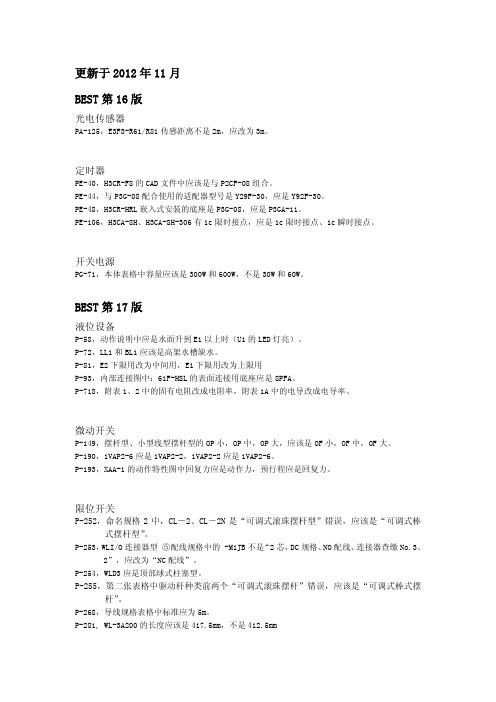
更新于2012年11月BEST第16版光电传感器PA-125,E3F3-R61/R81传感距离不是2m,应改为3m。
定时器PE-40,H3CR-F8的CAD文件中应该是与P2CF-08组合。
PE-44,与P3G-08配合使用的适配器型号是Y29F-30,应是Y92F-30。
PE-48,H3CR-HRL嵌入式安装的底座是P3G-08,应是P3GA-11。
PE-106,H3CA-8H、H3CA-8H-306有1c限时接点,应是1c限时接点、1c瞬时接点。
开关电源PG-71,本体表格中容量应该是300W和600W,不是30W和60W。
BEST第17版液位设备P-58,动作说明中应是水面升到E1以上时(U1的LED灯亮)。
P-72,LL1和BL1应该是高架水槽缺水。
P-81,E2下限用改为中间用,E1下限用改为上限用P-93,内部连接图中:61F-HSL的表面连接用底座应是8PFA。
P-718,附表1、2中的固有电阻改成电阻率,附表1A中的电导改成电导率。
微动开关P-149,摆杆型、小型线型摆杆型的OP小,OP中,OP大,应该是OF小,OF中,OF大。
P-190,1VAP2-6应是1VAP2-2,1VAP2-2应是1VAP2-6。
P-193,XAA-1的动作特性图中回复力应是动作力,预行程应是回复力。
限位开关P-252,命名规格2中,CL-2、CL-2N是“可调式滚珠摆杆型”错误,应该是“可调式棒式摆杆型”。
P-253,WLI/O连接器型⑤配线规格中的 -M1JB不是“2芯,DC规格、NO配线、连接器查缴No.3、2”,应改为“NC配线”。
P-254,WLD3应是顶部球式柱塞型。
P-255,第二张表格中驱动杆种类前两个“可调式滚珠摆杆”错误,应该是“可调式棒式摆杆”。
P-268,导线规格表格中标准应为5m。
P-281, WL-3A200的长度应该是417.5mm,不是412.5mmP-295,D4A-D00对应的驱动杆的种类不是“可调式滚珠²摆杆型”,应该改成“可调式棒式²摆杆型”。
Omron光电传感器选型指南说明书

HUMAN MACHINEINTERFACESENERGYMANAGEMENTSOLUTIONSFA COMPONENTSMACHINE VISIONSYSTEMSUV CURINGSYSTEMSCX-400CY-100EX-10EX-20EX-30EX-40CX-440EQ-30EQ-500MQ-WRXRT-610Hardly affected by colorThe color or size of the object does not affect its sensingperformance.Hardly affected by backgroundThe sensor does not detectthe background beyond theset distance since it is ofdistance adjustable type.RobustIts robust enclosure is made of die-cast zinc alloy.High-speed response time: 1 msIt can be used on a high speed assembly line.BASIC PERFORMANCEWaterproof IP67 (IEC)The equipment on which the sensor is mounted can bewashed without any problem.ENVIRONMENTAL RESISTANCENote: H owever, take care that if it is exposed to water splashesduring operation. It may detect a water drop itself.Insusceptible to dustThe sensing performanceis less affected by dust asit does not depend on theincident light intensity.has a specular surface.Adjustable Range Reflective Photoelectric SensorRX-LS200344FIBER SENSORSLASER SENSORS PHOTO-ELECTRIC SENSORS AREA SENSORS SAFETY LIGHT CURTAINS /SAFETY COMPONENTS PRESSURE / FLOW SENSORS INDUCTIVE PROXIMITY SENSORS PARTICULAR USE SENSORS SENSOR OPTIONS SIMPLE WIRE-SAVING UNITS WIRE-SAVING SYSTEMSMEASURE-MENT SENSORS STATIC CONTROL DEVICES LASER MARKERS PLC HUMAN MACHINE INTERFACES ENERGY MANAGEMENT SOLUTIONS FACOMPONENTS MACHINE VISION SYSTEMSUVCURINGSYSTEMSEX-Z CX-400CY-100EX-10 EX-20EX-30EX-40CX-440EQ-30EQ-500RX RT-6105 m cable length type5 m 16.404 ft cable length type (standard: 3 m 9.843 ft ) is also available for NPN output type.Model No.: RX-LS200-C5Accessory• MS-RX-1 (Sensor mounting bracket)Narrow-view slit mask• OS-RXL-□Protective tubeTwo M4 (length 16 mm 0.630 in )hexagon-socket-head bolts are attached.056 222 38 18*********************SEN TRONIC AG345Adjustable Range Reflective Photoelectric Sensor RX-LS200FIBERSENSORSLASERSENSORSPHOTO-ELECTRICSENSORSAREASENSORSSAFETY LIGHTCURTAINS /SAFETYCOMPONENTSPRESSURE /FLOWSENSORSINDUCTIVEPROXIMITYSENSORSPARTICULARUSESENSORSSENSOROPTIONSSIMPLEWIRE-SAVINGUNITSWIRE-SAVINGSYSTEMSMEASURE-MENTSENSORSSTATICCONTROLDEVICESLASERMARKERSPLCHUMANMACHINEINTERFACESENERGYMANAGEMENTSOLUTIONSFACOMPONENTSMACHINEVISIONSYSTEMSUVCURINGSYSTEMSEX-ZCX-400CY-100EX-10EX-20EX-30EX-40CX-440EQ-30EQ-500RXRT-610I/O circuit diagram Wiring diagramSymbols … D : Reverse supply polarity protection diodeZ D : Surge absorption zener diodeTr : NPN output transistor±10 %RX-LS200NPN output type 056 222 38 18*********************SEN TRONICAGAdjustable Range Reflective Photoelectric SensorRX-LS200346FIBER SENSORS LASER SENSORS PHOTO-ELECTRIC SENSORSAREA SENSORS SAFETY LIGHT CURTAINS /SAFETY COMPONENTS PRESSURE / FLOW SENSORS INDUCTIVE PROXIMITY SENSORS PARTICULAR USE SENSORS SENSOR OPTIONS SIMPLE WIRE-SAVING UNITS WIRE-SAVING SYSTEMSMEASURE-MENT SENSORS STATIC CONTROL DEVICES LASER MARKERS PLC HUMAN MACHINE INTERFACES ENERGY MANAGEMENT SOLUTIONS FACOMPONENTS MACHINE VISION SYSTEMS UVCURINGSYSTEMSEX-Z CX-400CY-100EX-10EX-20EX-30EX-40CX-440EQ-30EQ-500RX RT-610I/O circuit diagramWiring diagramNote: T he output does not incorporate a short-circuit protection circuit.Do not connect it directly to a power supply or a capacitive load.Symbols … D : Reverse supply polarity protection diodeZ D : Surge absorption zener diode Tr : PNP output transistorto 24 V DCSensing fields• Setting distance: 200 mm 7.874 in (Horizontal)• Setting distance: 200 mm 7.874 in (Vertical)• Setting distance: 150 mm 5.906 in (Horizontal)• Setting distance: 150 mm 5.906 in (Vertical)• Setting distance: 150 mm 5.906 in with slit mask (Vertical)• Setting distance: 150 mm 5.906 in with slit mask(Horizontal)0.3940.394Left Center in )S e t t i n g d i s t a n c e L (m m i n Up Center Operating point ℓ (mm in )0.3940.394S e t t i n g d i s t a n c e L (m m in Left Center in)0.1570.157S e t t i n g d i s t a n c e L (m mi nUp Center in )0.1570.157S e t t i n g d i s t a n c e L(m m i nLeft Center Operating point ℓ (mm in )0.1570.157S e t t i n g d i s t a n c e L (m m i nUp Operating point ℓ (mm in )0.1570.157S e t t i n g d i s t a n c e L (m m i nCorrelation between sensing object size and sensing range0.787 1.575 2.362 3.1503.937 in , 7.874 in , each, with white non-glossy 1.969 × 1.969 in ).side length a (mm in )S e n s i n g r a n g e L (m m i n D i s t a n c e L (m m i n RX-LS200-P PNP output type056 222 38 18*********************SEN TRONIC AG347Adjustable Range Reflective Photoelectric Sensor RX-LS200FIBERSENSORSLASERSENSORSPHOTO-ELECTRICSENSORSAREASENSORSSAFETY LIGHTCURTAINS /SAFETYCOMPONENTSPRESSURE /FLOWSENSORSINDUCTIVEPROXIMITYSENSORSPARTICULARUSESENSORSSENSOROPTIONSSIMPLEWIRE-SAVINGUNITSWIRE-SAVINGSYSTEMSMEASURE-MENTSENSORSSTATICCONTROLDEVICESLASERMARKERSPLCHUMANMACHINEINTERFACESENERGYMANAGEMENTSOLUTIONSFACOMPONENTSMACHINEVISIONSYSTEMSUVCURINGSYSTEMSEX-ZCX-400CY-100EX-10EX-20EX-30EX-40CX-440EQ-30EQ-500RXRT-610Correlation between material (50 × 50 mm 1.969 × 1.969 in) and sensing range200 mm 7.874 in100 mm 3.937 in50 mm 1.969 inWhitenon-glossypaperPlywoodCardboardCeramiccircuitboardGraynon-glossypaper(Lightness:3)BlackrubbeMirrorThese bars indicate the sensing rangewith respective objects when thedistance adjuster is set at the sensingrange of 200 mm 7.874 in, 100 mm3.937 in and 50 mm 1.969 in long,each, with white non-glossy paper.(GreenmaskedsurfaceGlassepoxyprintedcircuitboardSensingrangeL(mminWiring• The output of RX-LS200-P does not incorporate a short-circuit protection circuit. Do not connect it directly to apower supply or a capacitive load.Others• Do not use during the initial transient time (50 ms) afterthe power supply is switched on.Mounting• The tightening torque should be 1.17 N·m or less.• Care must be taken regarding the sensor mountingdirection with respect to the object’s direction of movement.Do not make the sensordetect an object in thisdirection because it maycause unstable operation.Sensing object Sensing object Sensing objectintersection of the “ ”mark on the lens faceand the “ ” line.• When detecting a specular object (aluminum or copperfoil) or an object having a glossy surface or coating,please take care that there are cases when the objectmay not be detected due to a small change in angle,wrinkles on the object surface, etc.• When a specular body is present below the sensor, usethe sensor by tilting it slightly upwards to avoid wrongoperation.Use conditions to comply with CE Marking• Following work must be done in case of using thisproduct as a CE marking (European standard EMCDirective) conforming product.Ensure that the shield is connected to 0 V or the actualground.• In case of connecting a sensor to power supply 0 V by usinga shield (piping, etc.)• In case of grounding by using a shield (piping, etc.)Note: The shield (piping, etc.) must be insulated.• If a specular body is present in the background, wrongoperation may be caused due to a small change in theangle of the background body. In that case, install thesensor at an inclination and confirm the operation withthe actual sensing object.• Do not install the sensor at a distance of less than 50 mm1.969 in from the object because the sensing is unstablein this range.Correct Correct Incorrect056 222 38 18*********************SEN TRONICAGAdjustable Range Reflective Photoelectric SensorRX-LS200348FIBER SENSORS LASER SENSORS PHOTO-ELECTRIC SENSORS AREA SENSORSSAFETY LIGHT CURTAINS /SAFETY COMPONENTS PRESSURE / FLOW SENSORSINDUCTIVE PROXIMITY SENSORS PARTICULAR USE SENSORSSENSOR OPTIONS SIMPLE WIRE-SAVING UNITS WIRE-SAVING SYSTEMSMEASURE-MENT SENSORS STATIC CONTROL DEVICES LASER MARKERS PLC HUMAN MACHINE INTERFACES ENERGY MANAGEMENT SOLUTIONS FACOMPONENTS MACHINE VISION SYSTEMSUVCURINGSYSTEMSEX-Z CX-400CY-100EX-10 EX-20EX-30EX-40CX-440EQ-30EQ-500RX RT-610Distance adjustmentSensorRX-LS200 RX-LS200-PProtective tube (Optional)PT-RX500 PT-RX1000MS-RX-1Sensor mounting bracket (Accessory)Assembly dimensions• Follow only steps 1 and 2 respectively. Since the sensing point may change depending on the sensing object, be sure to check the operation with the actual sensing object.<When a sensing object is approaching / moving away from the sensor><When a sensing object moves horizontally to the sensor>) hexagon-socket-AdjustersAdjusting procedure056 222 38 18*********************SEN TRONIC AG。
OMRON编码器说明书
᪡㆛
Ⳍֵ݇ᙃ
串行传送
对应同时输出多位数据的通常并联传送,可采用由一个 传送线进行系列化输出数据的形式,目的是节省连线, 在接受信号侧则变换成并联信号后使用。
⬉ܝӴᛳ఼
ԡ鼠Ӵᛳ఼
⌟䭓Ӵᛳ఼
㾚㾝Ӵᛳ఼ ᅝܼऎඳ Ӵᛳ఼ 䖥Ӵᛳ఼ ᖂൟ⬉ܝ Ӵᛳ఼ ᮟ䕀ᓣ 㓪ⷕ఼ 䍙ໄ⊶ Ӵᛳ఼ य़Ӵᛳ఼
1 增量式或绝对式
考虑到容许的成本,电源接通时的原点可否恢复、控 制速度、耐干扰性等,选择合适的类型。
2 分解率精度的选择
在考虑组装机械装置的要求精度和机械的成本的基础 上,选择最适合的产品。一般选择机械综合精度的1/2 ~1/4精度的分辨率。
3 外形尺寸
选定时还要考虑安装空间与选定轴的形态 (中空轴、 杆轴类)。
18位置,则代码的范围为从14位置到49位置。从49 ᡔᴃᣛफ
位置切换到14位置时,只改变1位,可见保持了格雷
码的性质。通过将该代码转换至14位置,就能转换
至从0位置开始的代码,然后进行使用。
(4) BCD代码
ᡔᴃ㆛
二进10进制代码 (Binary Coded Decimal Code)。
是分别用2进符号表示10进制各位的代码。
Ӵᛳ఼ 䖥Ӵᛳ఼
ᖂൟ⬉ܝ Ӵᛳ఼ ᮟ䕀ᓣ 㓪ⷕ఼ 䍙ໄ⊶ Ӵᛳ఼
य़Ӵᛳ఼
项目
特长
构造
输出波形
·本 型 号 能 根 据 轴 的 旋 转 位 移 量,
输出脉冲列。
其方式是通过其他计数器,计算输
ফܗܝӊ AⳌ⣁㓱 BⳌ⣁㓱
出脉冲数,通过计数检测旋转量。
·希望知道某输入轴位置的旋转量, 先按基准位置,使计数位的计数 值复位,然后再用计数器把由该 䕈 位置发出的脉冲数累加起来。
欧姆龙位移传感器设置使用说明
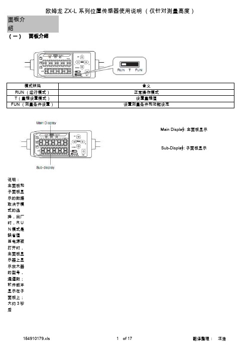
面板介绍(一)面板介绍说明:主面板和子面板显示的数据取决于模式的选择,出厂时,RUN模式是缺省值当电源被打开时,主面板显示器上显示放大器的型号,通道数;软件版本显示在子面板上;大约3秒后含义模式拨码RUN (运行模式)T(量程设置模式)FUN (测量条件设置)Main Display: 主面板显示Sub-Display: 子面板显示正常操作模式设置量程值设置测量条件和功能设定欧姆龙 ZX-L 系列位置传感器使用说明 (仅针对测量高度)的数据将会被显示。
模式当控制键被按下去后,依次显示量程值,电压值,电流值,接收的光数量值,分辨率。
例如:既可以显示上限下量程值,也可以显示下限值,这取决于量程开关的选择。
放大器上显示的字符和阿拉伯字母对照主面板显示实际的测量值(测量条件被设定后)T 子面板仅仅显示量程值 (可以上限值,也可以下限值)取决于量程开关的设定当控制键被按下去,依次显示功能参数名为主显示板上显示的参数,显示设定值FUN Run显示实际的测量值(测量条件被设定后)(当保持键被设定后,主显示板显示保持的测量值)面板上的控制键介绍和操作左键右键上键下键设定测量条件为了在主面板上显示目标功能,为设定测量条件,在子面板上显示要求的值,举例: 设定一个峰值保持,来说明如何设定测量条件1 设置模式开关到FUN功能说明FUN 操作键光标键改变子显示板上的内容选择数字位功能改变键执行选项输入RunT 功能改变键用于改变数字对射光电头是作为输入信号(我公司是反射光电)确定键1.按住保持1秒钟,是零复位;2. 按住此键和右箭头键并保持3秒钟,取消零复位1 确认量程值的设定2.执行教学功能确定设定值和条件2. 用左右键去选择“ HOLD”键,在主显示板显示3. 按上或下键 (子显示板闪烁)4.用上键和下键去选择 【P-H】5.按确定键去确认设置P---PeakH---Hold基本操作讲解(一)直接输入量程数字值为量程输入和输出设定,输入数字值,举一个实例来说明下限量程值的输入目的:改变下限量程40000 到39000先将模式开关拨至“T"1.设置模式开关到 ”T“2 设置开关到”L“测量值显示在主屏幕上,子屏幕显示当前的设定值3 按任意光标键,子屏幕上第1位数字闪烁,可以直接输入4 用上键和下键将第1位数字改成 ”3“5 用左或右键将光标移动到其他数字位6 用上下键将数字改成” 9“备注: 用左键将光标移动到最左边,在按左键;用右键将光标移动到最右边,再按右键,将取消当前的设定,返回修改前的数字。
欧姆龙PLC样本与手册全集
欧姆龙PLC样本与手册全集小型机CP1H选型样本(中文)R05-CN-03CP1H/CP1L选型样本(中文)SBCA-C-051DCP1L选型样本(英文)P20E-EN-01CP1E中英文选型样本CP1H操作手册(中文)W450-CN5-02CP1H操作手册(英文)W450-E1-01CP1L操作手册(中文)W462-CN5-03CP1L操作手册(英文)W462-E1-06CP1E单元软件用户手册(中英文)W480-E1-01W480-CN5-01 CP1E单元硬件用户手册(中英文)W479-E1-01W479-CN5-01 CP1E单元硬件用户手册(英文)(包含NA)W479-E1-03 CP1H/CP1L编程手册(英文)W451-E1-03CP1H/CP1L编程手册(中文)CP1E指令参考手册(中文)W483-CN5-04CP1E指令手册(英文)CPM1A-V1选型样本(英文)P039E1-11CPM1A操作手册(英文)W317-E1-4CPM1/1A/2A/2C/SRM1编程手册(英文)W353-E1-1CPM1A操作手册(中文)OMP-ZCO97101BCPM1A/2A/2AH/2C编程手册(中文)CPM1操作手册(英文)W262-E1-4CPM2A/2C选型样本(英文)P049-E1-08CPM2AH选型样本(中文)CPM2AH-S选型样本(中文).P01Z-CN-01CPM2A操作手册(英文)W352-E1-1CPM2AH-S操作手册(中文)CPM2A/CPM2AH操作手册(中文)CPM2C选型样本(英文)CPM2C操作手册(英文)W356-E1-08CPM2B操作手册(中文)OMP-AD000102ACPM2B-S001M-DRT操作手册(英文)W399-E1-1中型机CJ1系列选型样本(中文)CJ2H/CJ2M选型样本(中文)SBCE-CN-058DC200HX/C200HG/C200HE选型样本(中文)CJ1M内置I/O操作手册(中文)W395-C1-01 CJ1操作手册(中文)W393-C1-02CJ1编程手册(中文)W340-C1-08CJ1最新编程手册(英文)W340-E1-1CJ2CPU单元硬件操作手册(中文)W472-CN5-06 CJ2操作手册(英文)W472-E1-01CJ2M-MD操作手册(英文)W486-E1-01CJ2编程手册(英文)W473-E1-01CJ1W-AD/DA操作手册(中文)W345-C1-05CJ1W-TC操作手册(中文)W396CJ1W-PTS操作手册(英文)W368-E1-07C200HX/HG/HE编程手册(中文)OEZ-ZCP97201AC200HE/HG/HX操作手册(中文)OEZ-ZCI96201AC200H模拟量(AD001/DA001)操作手册(中文)OMP-ZCO99406A C200H模拟量I(AD003/DA003)操作手册(英文)W325-E1-04 C200H-TC温度控制单元操作手册(英文)W124-E1-5C200H操作手册(英文)W130-E3-5C200HS安装手册(英文)C200HS操作手册(英文)CQM1H选型样本(中文)CQM1H操作手册(中文)CQM1H编程手册(中文)CQM1H系列CPU和内装板操作手册(英文)CQM1H系列CPU和内装板编程手册(英文)CQM1H特殊I/O单元操作手册(中文)CQM1H/CQM1特殊I/O手册(英文)大型机CS1W-PTS过程控制I/O模块操作手册(英文)W368-E1-07CS1-H选型样本(中文)CS1D选型样本(中文)CS1可编程控制器操作手册(中文)W339-CN5-10CS1编程手册(中文)W340-C1-08CS1最新编程手册(英文)CS1D双机操作手册(英文)W405-E1-06CS1W-AD/DA操作手册(中文)W345-C1-05CS1W-AD/DA最新操作手册(英文)W345-E1-11C500安装手册(英文)W132-E1-3DC500编程手册(英文)W131-E1-02C500-LK操作手册(英文)W143-E1-05串口通讯C200HW-COM01/02/03/04/05/06通讯板操作手册(英文)-W304-E1-05通讯命令参考手册(英文)W342-E1-15CS1/CJ1W-SCU/SCB串行通讯单元/板卡操作手册(英文)-W336-E1-10 CQM1H-SCB41操作手册(英文)-W365-E1-02NT-AL001使用手册(英文)C200HPC-Link系统手册(英文)-W135-E1-2B以太网CS1-ETN01/11和CJ1-ETN11操作手册(英文)-W343-E1-07CS1/CJ1-ETN21操作手册(英文)-W420-E1-06CS1/CJ1-ETN21应用手册(英文)-W421-E1-04CS1D-ETN21D操作手册(英文)-W430-E1-02CJ1M-CPU1□-ETN操作手册(英文)-W441-E1-03ControllerLink3G8F7-CLK21/52/12安装指南(英文)W388-E1-2C200HW/CVM1-CLK21操作手册(中文)-OEZ-ZCO97404ACS/CJ1W/C200HW/CVM1/CQM1H-CLK21CS1W-RPT01/02/03操作手册(英文)-W309-E1-113G8F7-CLK12/21/52(-EV1)/13/23/53(-E)操作手册(英文)-W383-E1-04CS1W/CVM1-CLK12/52/13/53操作手册(英文)-W370-E1-07DeviceNet(Compobus/D)CS1/CJ1-DRM21-V1操作手册(英文)-W380-E1-07CVM1/C200HW-DRM21/CQM1-DRT21DRT1系列操作手册(英文)-W267-E1-6 CS1/CJ1系列DRM21操作手册(中文繁体)-SBCD-314H-TW5-01ITNC-EPX01/ITNC-EPX01-DRM开放网络控制器操作手册(英文)-V228-E1-02 C200HW/CQM1-DRT21/DRT1系列操作手册(英文)-W347-E1-06DeviceNet操作手册(英文)-W267-E1-113G3MV-PDRT1-SINVDeviceNet通讯单元操作手册(英文)-I529-E1-02DRT2系列从单元操作手册(英文)-W404-E1-08NT-DRT21DeviceNet接口单元操作手册(英文)-V066-E1-1DRT-COM/GT1系列DeviceNetMultipleI/O操作手册(英文)-W438-E1-05 CPM2C-S/CPM2C-S100C/S110C/S100C-DRT操作手册(英文)-W337-E1-13G3FV-PDRT1-SIN操作手册(英文)-I525-E1-023G3MV/3G3RV-PDRT2Devicenet操作手册(英文)-I539-E1-03GRT1-DRT模块操作手册(英文)-W455-E1-06OMNUCW系列伺服驱动器R88A-NCW152-DRT操作手册(英文)-I538-E1-01 OMNUCW系列伺服驱动器R88A-NCW152-DRT选型样本(英文)-DS13P1 CS/CJ1W-DRM21安装AB公司DRT丛站使用说明(英文)Compobus/SC200HW/CJ1/CQM1-SRM21SRT1/SRT2操作手册(英文)-W226-E1-09 CompoNetCS/CJ1W-CRM21操作手册(英文)-W456-E1-03CompoNet从站模块和中继模块操作手册(英文)W457-E1-03 Profibus-DPC200HW-PRM21PROFIBUS-DP主单元操作手册(英文)-W349-E1-1N CS1W/CJ1W-PRM21Profibus主单元操作手册(英文)-W409-E2-03C200HW-PRT21操作手册(英文)-W901-E2-1CJ1W-PRT21操作手册(英文)-W408-E2-02PRT1-COM/GT1操作手册(英文)-W900-E2-02CQM1H-PRT21操作手册(英文)。
Omron E3F1光电传感器说明书
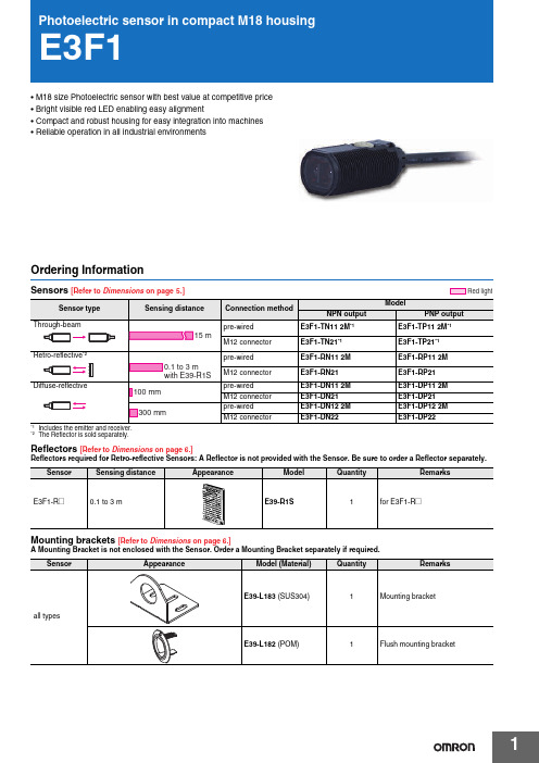
1•M18 size Photoelectric sensor with best value at competitive price •Bright visible red LED enabling easy alignment•Compact and robust housing for easy integration into machines •Reliable operation in all industrial environmentsOrdering InformationSensors [Refer to Dimensions on page 5.]Reflectors [Refer to Dimensions on page 6.]Reflectors required for Retro-reflective Sensors: A Reflector is not provided with the Sensor. Be sure to order a Reflector separately.Mounting brackets [Refer to Dimensions on page 6.]A Mounting Bracket is not enclosed with the Sensor. Order a Mounting Bracket separately if required.*2The Reflector is sold separately.Red lightSensorSensing distanceAppearanceModelQuantityRemarksE 3F1-R @0.1 to 3 m E39-R1S 1for E 3F1-R @E3F12Sensor I/O connectorsModels for Connectors: A Connector is not provided with the Sensor. Be sure to order a Connector separately. SpecificationsSensor Size Cable Appearance Cable type ModelM12 connector types M12S tandard2 m4-wireXS2F-M12PVC4S2M-EU5 m XS2F-M12PVC4S5M-EU2 m XS2F-M12PVC4A2M-EU5 m XS2F-M12PVC4A5M-EUSensing method Through-beam Retro-reflective Diffuse-reflective Model NPNoutputPre-wired E3F1-TN11 2M E3F1-RN11 2M E3F1-DN11 2M E3F1-DN12 2MM12 Connector E3F1-TN21E3F1-RN21E3F1-DN21E3F1-DN22 PNPoutputPre-wired E3F1-TP11 2M E3F1-RP11 2M E3F1-DP11 2M E3F1-DP12 2MItem M12 Connector E3F1-TP21E3F1-RP21E3F1-DP21E3F1-DP22Sensing distance15 m0.1 to 3 m(with E39-R1S)100 mm(white paper:300⨯300mm)300 mm(white paper:300⨯300mm)Spot diameter (typical)——40 ⨯ 45 mmS ensing distanceof 100 mm40 ⨯ 50 mmS ensing distanceof 300 mmDirectional angle2° min.2° min.——Light source (wavelength)Red LED (624 nm)Power supply voltage10 to 30 VDC (include voltage ripple of 10%(p-p) max.)Current consumption40 mA max.(Emitter 25 mA max.Receiver 15 mA max.)25 mA max.Control outputNPN/PNP (open collector)Load current: 100 mA max. (Residual voltage: 3 V max.), Load power supply voltage: 30 VDC max. Operation mode Light-ON/Dark-ON selectable by wiringIndicatorOperation indicator (orange)S tability indicator (green)Power indicator (green): only Emitter of Through-beamProtection circuitsReversed power supply polarity protection, Output short-circuit protection and Reversed output po-larity protectionResponse time0.5 msSensitivity adjustment One-turn adjusterAmbient temperature range Operating: -25 to 55°C/ S torage: -30 to 70°C (with no icing or condensation)Ambient humidity range Operating: 35 to 85%RH/ S torage: 35 to 95%RH (with no condensation)Degree of protection IEC: IP66Weight(packedstate/onlysensor)Pre-wired cable (2M)Approx. 110 g/Approx. 50 g,respectivelyApprox. 60 g/ Approx. 50 gConnectorApprox. 30 g/Approx. 10 g,respectivelyApprox. 20 g/ Approx. 10 gMaterialCase AB SLens and Display PMMAAdjuster POMNut AB SAccessoriesInstruction sheetM18 nuts (4 pcs)Instruction sheetM18 nuts (2 pcs)S traightAngleE3F13Output circuit diagramPNP OutputNPN OutputConnector Pin ArrangementM12 Connector Pin ArrangementConnectors (Sensor I/O connectors)M12 4-wire Connectors3124Classification Wire color Connector pin No.Application DCBrown ➀Power supply (+V)White ➁L/on · D/on selectable Blue ➂Power supply (0 V)Black➃OutputE3F14Nomenclature*The Emitter has two Power indicators (Green) instead of the S tability indicator (Green) and the Operation indicator (Orange).Safety PrecautionsRefer to Warranty and Limitations of Liability.This product is not designed or rated for directly orindirectly ensuring safety of persons. Do not use itfor such a purpose.Never use the product with an AC power supply.Do not use the product with voltage in excess of therated voltage.Do not use the product with incorrect wiring.Otherwise, explosion, fire, malfunction may result.Be sure to follow the safety precautions below for added safety.1.Do not use the sensor under the environment with explosive,flammable or corrosive gas.2.Do not use the sensor under the oil or chemical environment.3.Do not use the sensor in the water, rain or outdoors.4.Do not use the sensor in the environment where humidity is highand condensation may occur.5.Do not use the sensor under the environment under the otherconditions in excess of rated.6.Do not use the sensor in place that is exposed by direct sunlight.7.Do not use the sensor in place where the sensor may receivedirect vibration or shock.8.Do not use the thinner, alcohol, or other organic solvents.9.Never disassemble, repair nor tamper with the sensor.10.Please process it as industrial waste.ying S ensor wiring in the same conduit or duct as high-voltagewires or power lines may result in malfunction or damage due toconduit or use shielded cable.2.Do not pull on the cable with excessive force.3.If a commercial switching regulator is used, ground the FG (frameground) terminal.4.The sensor will be available 100 ms after the power supply is tunedON. S tart to use the sensor 100 ms or more after turning ON thepower supply. If the load and the sensor are connected to separatepower supplies, be sure to turn ON the sensor first.5.Output pulses may be generated even when the power supply isOFF. Therefore, it is recommended to first turn OFF the powersupply for the load or the load line.6.The sensor must be mounted using the provided nuts. The propertightening torque range is between 0.4 and 0.5 N·m.St ab ility indic a tor(Green)Oper a tion indic a tor(Or a nge)Sen s itivity a dj us terStraightwith an adjuster:E3F1-T@-DE3F1-R@E3F1-D@without an adjuster:E3F1-T@-L *WARNINGCAUTIONPrecautions for Safe UsePrecautions for Correct UseE3F15DimensionsSensors(Unit: mm)Tolerance class IT16 applies to dimensions in this data sheet unless otherwise specified.dia.0 (AWG26)standard length 2 mPre-wired Models E3F1-T @E3F1-R @E3F1-D @Suitable models E3F1-T @11Suitable models E3F1-R @11E3F1-D @1@*Suitable models E3F1-T @11-D E3F1-R @12E3F1-D @1@Mounting HolesLeft side viewLeft side viewFront viewM12 Connector Models E3F1-T @E3F1-R @E3F1-D@dia.0Suitable models E3F1-T @21Suitable models E3F1-R @21E3F1-D @2@Mounting HolesTerminal No.Specification1+V 2L/on · D/on selectable 30V 4Output*Suitable models E3F1-T @21-D E3F1-R @22E3F1-D @2@Left side viewLeft side viewFront viewRight side viewAttached nutE3F16Accessories (Order Separately)E3F17Read and Understand This CatalogPlease read and understand this catalog before purchasing the products. Please consult your OMRON representative if you have any questions orcomments.WARRANTYOMRON's exclusive warranty is that the products are free from defects in materials and workmanship for a period of one year (or other period if specified) from date of sale by OMRON.OMRON MAKES NO WARRANTY OR REPRESENTATION, EXPRESS OR IMPLIED, REGARDING NON-INFRINGEMENT, MERCHANTABILITY, OR FITNESS FOR PARTICULAR PURPOSE OF THE PRODUCTS. ANY BUYER OR USER ACKNOWLEDGES THAT THE BUYER OR USER ALONE HAS DETERMINED THAT THE PRODUCTS WILL SUITABLY MEET THE REQUIREMENTS OF THEIR INTENDED USE. OMRON DISCLAIMS ALL OTHER WARRANTIES, EXPRESS OR IMPLIED.LIMITA TIONS OF LIABILITYOMRON SHALL NOT BE RESPONSIBLE FOR SPECIAL, INDIRECT, OR CONSEQUENTIAL DAMAGES, LOSS OF PROFITS OR COMMERCIAL LOSS IN ANY WAY CONNECTED WITH THE PRODUCTS, WHETHER SUCH CLAIM IS BASED ON CONTRACT, WARRANTY, NEGLIGENCE, OR STRICT LIABILITY.In no event shall the responsibility of OMRON for any act exceed the individual price of the product on which liability is asserted.IN NO EVENT SHALL OMRON BE RESPONSIBLE FOR WARRANTY, REPAIR, OR OTHER CLAIMS REGARDING THE PRODUCTS UNLESSOMRON'S ANALYSIS CONFIRMS THAT THE PRODUCTS WERE PROPERLY HANDLED, STORED, INSTALLED, AND MAINTAINED AND NOTSUBJECT TO CONTAMINATION, ABUSE, MISUSE, OR INAPPROPRIATE MODIFICATION OR REPAIR.SUITABILITY FOR USEOMRON shall not be responsible for conformity with any standards, codes, or regulations that apply to the combination of products in the customer's application or use of the products.At the customer's request, OMRON will provide applicable third party certification documents identifying ratings and limitations of use that apply to the products. This information by itself is not sufficient for a complete determination of the suitability of the products in combination with the end product, machine, system, or other application or use.The following are some examples of applications for which particular attention must be given. This is not intended to be an exhaustive list of all possible uses of the products, nor is it intended to imply that the uses listed may be suitable for the products:•Outdoor use, uses involving potential chemical contamination or electrical interference, or conditions or uses not described in this catalog.•Nuclear energy control systems, combustion systems, railroad systems, aviation systems, medical equipment, amusement machines, vehicles, safety equipment, and installations subject to separate industry or government regulations.•Systems, machines, and equipment that could present a risk to life or property.Please know and observe all prohibitions of use applicable to the products.NEVER USE THE PRODUCTS FOR AN APPLICATION INVOLVING SERIOUS RISK TO LIFE OR PROPERTY WITHOUT ENSURING THAT THESYSTEM AS A WHOLE HAS BEEN DESIGNED TO ADDRESS THE RISKS, AND THAT THE OMRON PRODUCTS ARE PROPERLY RATED ANDINSTALLED FOR THE INTENDED USE WITHIN THE OVERALL EQUIPMENT OR SYSTEM.PROGRAMMABLE PRODUCTSOMRON shall not be responsible for the user's programming of a programmable product, or any consequence thereof.CHANGE IN SPECIFICA TIONSProduct specifications and accessories may be changed at any time based on improvements and other reasons.It is our practice to change model numbers when published ratings or features are changed, or when significant construction changes are made.However, some specifications of the products may be changed without any notice. When in doubt, special model numbers may be assigned to fix or establish key specifications for your application on your request. Please consult with your OMRON representative at any time to confirm actualspecifications of purchased products.DIMENSIONS AND WEIGHTSDimensions and weights are nominal and are not to be used for manufacturing purposes, even when tolerances are shown.PERFORMANCE DA TAPerformance data given in this catalog is provided as a guide for the user in determining suitability and does not constitute a warranty. It may represent the result of OMRON’s test conditions, and the users must correlate it to actual application requirements. Actual performance is subject to the OMRONWarranty and Limitations of Liability.ERRORS AND OMISSIONSThe information in this document has been carefully checked and is believed to be accurate; however, no responsibility is assumed for clerical,typographical, or proofreading errors, or omissions.Cat. No. E94E-EN-01In the interest of product improvement, specifications are subject to change without notice. OMRON EUROPE B.V.Wegalaan 67-69,NL-2132 JD, Hoofddorp,The NetherlandsPhone:+31 23 568 13 00Fax:+31 23 568 13 88www.industrial.omron.eu。
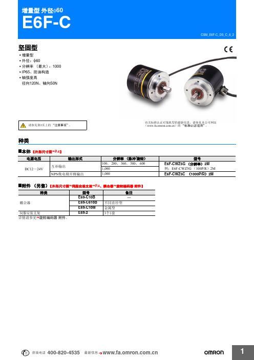
欧姆龙 旋转编码器E6F-C 产品手册
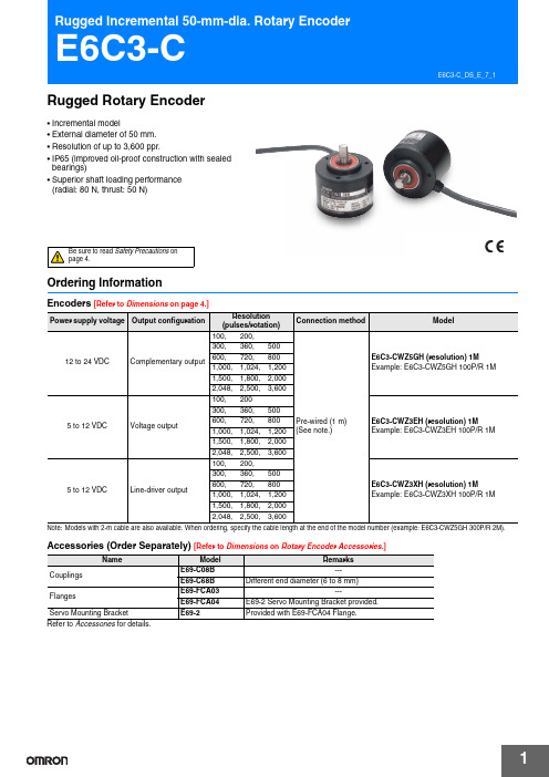
CSM_E6F-C_DS_C_6_2增量型 外径φ60E6F-C坚固型•增量型•外径:φ60•分辨率(最大):1000•IP65、防油构造•轴强度高径向120N 、轴向50N请参见第3页上的“注意事项”。
有关标准认证对象机型的最新信息,请参见本公司网站( )的“标准认证/适用”。
种类■本体【外形尺寸图➜P.4】■附件(另售)【外形尺寸图➜伺服安装支架➜P.4、耦合器➜旋转编码器 附件】详情请参见➜旋转编码器 附件。
种类型号备注耦合器E69-C10B ─E69-C610B 不同直径型E69-C10M 金属型伺服安装支架E69-23个1套电源电压输出形式分辨率(脉冲/旋转)型号DC12~24V互补输出100、200、360、500、600E6F-CWZ5G (分辨率) 2M 例:E6F-CWZ5G (100P/R ) 2M 1,000NPN 集电极开路输出1,000E6F-CWZ5C (1000P/R ) 2M额定规格/性能*1.接通电源时,流过约9A 的浪涌电流。
(时间:约5μs)*2.关于互补输出右图表示输出回路有NPN 与PNP 这2种输出晶体管。
根据输出信号“H ”、“L ”,2种输出晶体管互相交叉进行“ON ”、“OFF ”动作。
使用时,请分别拉上、拉下正电源和0V 。
互补输出分为输出电流流出及流入2种动作,特征是信号的上升、下降速度快,可进行导线的长距离延长。
可与开路集电极输入设备(NPN 、PNP )连接。
项目型号E6F-CWZ5GE6F-CWZ5C电源电压DC12V -10%~24V +15% 纹波 (p-p) 5%以下消耗电流 *1100mA 以下输出相A 相、B 相、Z 相分辨率(脉冲/旋转)100、200、360、500、600、1,0001,000输出形式辅助驱动输出 *2NPN 集电极开路输出输出容量输出电压:VH =V CC -3V 以上(I O =30mA )、VL =2V 以下(I O =-30mA )输出电流:±30mA 施加电压:DC30V 以下负载电流:35mA 以下残留电压:0.4V 以下(负载电流35mA 时)最高响应频率 83kHz输出相位差A 相、B 相的相位差90±45° (1/4T ±1/8T)输出上升、下降时间1μs 以下(导线长度:2m 、输出电流:30mA )1μs 以下导线长度:2m 、控制输出电压:5V 、负载电阻:1k Ω起动转矩常温时:10mN ·m 以下、低温时:15mN ·m 以下惯性力矩3×10⁻⁶kg ·m 2以下(600P/R 以下为1.5×10⁻⁶kg ·m 2以下)最大轴负载径向120N 轴向50N 允许最高转速5,000r/min保护回路电源反接保护、输出负载短路保护环境温度范围工作时:-10~+70℃、保存时:-25~+85℃(无结冰)环境湿度范围工作时、保存时:各35~85%RH (无结露)绝缘电阻20M Ω以上(DC500V 兆欧表)导线端整体与外壳间耐电压AC500V 50/60Hz 1min 导线端整体与外壳间振动(耐久)10~500Hz 上下振幅 2mm 或150m/s 2 X 、Y 、Z 各方向 扫频11min/次 扫频3次冲击(耐久)1,000m/s 2 X 、Y 、Z 各方向 3次保护结构 IEC 标准 IP65、公司内部标准 防油连接方式导线引出型(标准导线长2m )材质外壳锌合金本体铝轴SUS420J2质量(包装后)约400g附件使用说明书 注:耦合器、支架、六角扳手另售输入输出段回路图注1.屏蔽线的外芯(屏蔽)没有连接内部及外壳。
Omron 光电传感器选择指南说明书
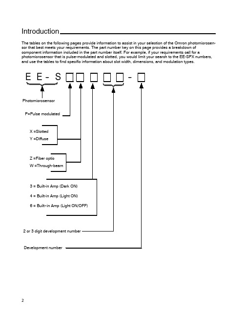
IntroductionThe tables on the following pages provide information to assist in your selection of the Omron photomicrosen-sor that best meets your requirements.The part number key on this page provides a breakdown of component information included in the part number itself.For example,if your requirements call for a photomicrosensor that is pulse-modulated and slotted,you would limit your search to the EE-SPX numbers, and use the tables to find specific information about slot width,dimensions,and modulation types.E E--S--PhotomicrosensorP=Pulse modulatedX=SlottedY=DiffuseZ=Fiber opticW=Through-beam3=Built-in Amp(Dark ON)4=Built-in Amp(Light ON)6=Built--in Amp(Light ON/OFF)2or3digit development numberDevelopment numberAmplified PhotomicrosensorsJ SLOT (TRANSMISSIVE)Slot width Appearance and dimensions (mm)Model Output Optical modulation Aperture width (mm)and orientationPage 3.6mm21.2EE-SPX740Dark-ON Modulated24257.4EE-SPX840Light-ON 2424EE-SPX301Dark-ON 58267EE-SPX401Light-ON 58EE-SPX306-W2ADark-ON 307.42521.2EE-SPX406-W2A Light-ON 3021.2EE-SPX742Dark-ON 24137EE-SPX842Light-ON 0.52421.2EE-SPX302-W2ADark-ON 30137EE-SPX402-W2ALight-ON 3021.2EE-SPX743Dark-ON 24137EE-SPX843Light-ON 2421.27EE-SPX304-W2ADark-ON 3013EE-SPX404-W2A Light-ON 305.0mm15.5EE-SPX741Dark-ON 2427.26.95EE-SPX841Light-ON 2427.215.5EE-SPX305-W2A Dark-ON3015.5EE-SPX405-W2A Light-ON 0.83013.0mmEE-SPX303Dark-ON 54267.4EE-SPX303-15426EE-SPX403Light-ON0.554(This table continues on the next page.)Slot (transmissive)--continued from previous pageSlot width Appearance and dimensions (mm)Model OutputOptical modulation Aperture width (mm)and orientationPage 5.0mm222EE-SX670Light-ON/Dark-ONNon-modulated3822.26.95EE-SX670A 4625.4EE-SX470Light-ON38155EE-SX671Light-ON/Dark-ON 3815.514.5EE-SX671A g 4626.2EE-SX471Light-ON38222EE-SX672Light-ON/Dark-ON3822.226EE-SX672A 4613.4EE-SX472Light-ON38222EE-SX673Light-ON/Dark-ON3822.212.8EE-SX673A 4613.4EE-SX473Light-ON 38155EE-SX674Light-OFF/ON3815.5215EE-SX674A 4621.513.6EE-SX474Light-ON 083818EE-SX770Dark-ON0.8344EE-SX770A31.1EE-SX870Light-ONEE-SX870A EE-SX771Dark-ON 342113EE-SX771AEE-SX871Light-ON18EE-SX871A EE-SX772Dark-ON3431.119.1EE-SX772AEE-SX872Light-ON12EE-SX872AJ DIFFUSESensing distance Sensing method Appearance and dimensions (mm)Model Output Optical modulation Features Page 5.0mmDiffuse reflective20Horizontal modelEE-SPY301Dark-ON ModulatedWide operating voltage range 64267EE-SPY401Light-ON (5to 24VDC)Built-in LED indicatorControl output:6420Vertical modelEE-SPY302Dark-ON p 80mA64267EE-SPY402Light-ON641to 5mm2525.46.95Horizontal modelEE-SY671Light-ON/Dark-ONNon-modulatedBuilt-in sensitivity adjusterWide operating voltage range (5722525.46.95Vertical modelEE-SY672Light-ON/Dark-ONto 24VDC)Output mode selectable72EE-SB5MLight-ON Incorporated 68222EE-SB5MC Dark-ON filter cuts off visible light 6822.2695EE-SB5V Light-ONSensitivity dj t t 686.95EE-SB5VC Dark-ON y adjustment 6819mm (3/4")25.4EE-SB5V-ELight-ON terminals incorporated 682to 6mm (approx.Convergent reflective 22.8Horizontal modelEE-SPY311Dark-ON ModulatedDetects objects against 761/4")268EE-SPY411Light-ON mirror-like surfacesat a distance of more 7622.8Vertical modelEE-SPY312Dark-ON 20mm or more.Detects minute or black objects.76268EE-SPY412Light-ON 76200mmDiffuse retro--EE-SPZ301-ADark-ON Long-distance detection with 80reflective7.42625EE-SPZ401-ALight-ONthe E39-R1Reflector80Note:The maximum detectable distance of each reflective photomicrosensor is based on detecting a piece of white paper with areflection factor of 90%.J FIBER-OPTIC7.42625J THROUGH--BEAMSensing distance Appearance and dimensions (mm)Model Output Optical modulation Detectable object (mm)Page 1m27EE-SPW311Dark-ON ModulatedOpaque:5dia.min.8625.48EE-SPW411Light-ON 8630cm125.8EE-SPW321(-A)Dark-ON Opaque:2dia.min.907.54610.712EE-SPW421(-A)Light-ON90Specialty PhotomicrosensorsSensing Distance Sensing Method Appearance and dimensions (mm)Model Output Optical modulation Features Page 4mmReflective3031.915.4Z4D-F04AAnalogNon-modulatedResolution down to 5μm.1024mmReflective3031.915.4Z4D-F04DON/OFFResolution down to 5μm.1025mmInductive sensing(unshielded)641.328E2R-A01NPN open collectorNoneHigh response frequency of 5khz minimum.98J LIQUID LEVEL SENSORSlot width Appearance and dimensions (mm)Model OutputOptical modulation Aperture width (mm)and orientationPage 13.0mm7.417.22616EE-SPX613Light-ON/Dark-ON Modulated0.896J CONNECTORSModel AppearanceApplicable sensorsEE-1001EE-SX470/470P/670/670P EE-SX471/471P/671/671P EE-SX472/472P/672/672P EE-SX473/473P/673/673P EE-SX474/474P/674/674P EE-1006The connectorincorporates a 2-m wire harness.EE-SX670A/670R EE-SX671A/671R EE-SX672A/672R EE-SX673A/673R EE-SX674A/674REE-SPX303/303-1/403EE-SY671/672EE-SB5M(C)/SB5V(C)EE-SB5V-EEE-SPY311/411/312/412EE-SPW311/411EE-1006A Connector HolderWhen using the EE-1006connectorEE-1006D,1006L The connectorincorporates a 2-m wire harness.EE-SPW311/411EE-1002EE-SPX301/-SPX401,EE-SPY301/-SPY401,EE-SPY302/-SPY402,EE-SPZ301-A/-SPZ401-A,EE-SPZ301Y-01/-SPZ401Y-01,EE-SPZ301W-01/-SPZ401W-01,EE-SPZ301W-02/-SPZ401W-02,EE-1003The connectorincorporates a 1-m wire harness.EE-SPZ301/-SPZ401EE-1003A Connector HolderEE-1010D Z4DEE-1013EE-SPX740/840E22-01E2R-A01J NPN-PNP OUTPUT CONVERTERModel Appearance Applicable sensor Page120 EE-2001EE-SPX301,EE-SPX401,EE-SPY301,EE-SPY401,EE-SPY302,EE-SPY402EE-SPZ301-A,EE-SPZ401-A,EE-SPZ301Y-01,EE-SPZ401Y-01,EE-SPZ301W-01EE-SPZ401W-01EE-SPZ301W-02,EE-SPZ401W-02,EE-SPZ301,EE-SPZ401120 EE-2002EE-SX670,EE-SX670-A,EE-SX671,EE-SX671-A,EE-SX672,EE-SX672-A,EE-SX673,EE-SX673-A,EE-SX470,EE-SX471,EE-SX472,EE-SX473,EE-SPY311,EE-SPY312,EE-SPY411,EE-SPY412,EE-SY671,EE-SY672,EE-SPX303,EE-SPX403,EE-SPW311,EE-SPW411,EE-SB5V,EE-SB5V-E,EE-SB5VC,EE-SB5M,EE-SB5MC。
OMRON编码器说明书

启动转矩
旋转式编码器的轴旋转启动时必须的旋转力矩。通常旋 转时,一般取比本值低的值。轴为防水用密封设计时, 启动转矩的值较高。
1360
ᡔᴃ㆛ᮟ䕀ᓣ㓪ⷕ఼
惯性力矩
表示旋转式编码器的旋转启动、停止时的惯性力的大 小。
轴容许力
是加在轴上的负载负重的容许量。径向以直角方向对轴 增加负重,而轴向以轴方向增加负重。 两者都为轴旋转时容许负重,该负重的大小对轴承的寿 命产生影响。
00 0 0 1 0 1
6
0 0 1 1 0 00 0 1 0 1
00 0 0 1 1 0
7
0 0 1 1 1 00 0 1 0 0
00 0 0 1 1 1
8
0 1 0 0 0 00 1 1 0 0
00 0 1 0 0 0
9
0 1 0 0 1 00 1 1 0 1
00 0 1 0 0 1
10
0 1 0 1 0 00 1 1 1 1
1361
ᡔᴃ㆛ᮟ䕀ᓣ㓪ⷕ఼
中空轴型 (空心轴型)
旋转轴为中空轴形状,通过将驱动侧的轴直接与中空孔 连接,可节省轴方向的空间。 以板簧为缓冲,吸收驱动轴的振动等
金属盘
编码器的旋转板 (盘)是用金属制成的,与玻璃旋转板 (盘)相比,更强化了耐冲击性。但受到狭缝加工的制 约,不能应用于高分辨率。
伺服装置
③可对旋转方向进行检测。
增量型中可通过 A 相和 B 相的输出时间,绝对型中可 通过代码的增减来掌握旋转方向。
④请根据丰富的分辨率和输出型号,选择最合适的 传感器。
根据要求精度和成本、连接电路等,选择适合的传感 器。
ᡔᴃᣛफ
ᡔᴃ㆛ ᪡㆛ Ⳍֵ݇ᙃ
⬉ܝӴᛳ఼ ԡ鼠Ӵᛳ఼ ⌟䭓Ӵᛳ఼ 㾚㾝Ӵᛳ఼ ᅝܼऎඳ Ӵᛳ఼ 䖥Ӵᛳ఼ ᖂൟ⬉ܝ Ӵᛳ఼ ᮟ䕀ᓣ 㓪ⷕ఼ 䍙ໄ⊶ Ӵᛳ఼ य़Ӵᛳ఼
欧姆龙旋转编码器HEDS说明
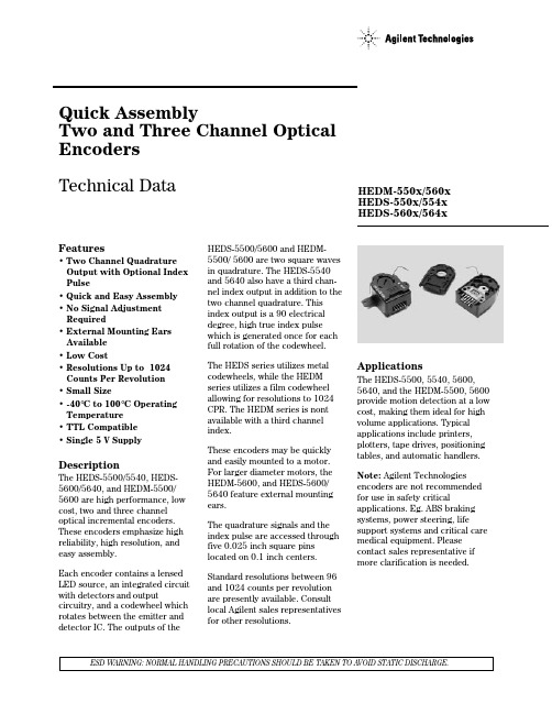
Quick AssemblyTwo and Three Channel Optical Encoders Technical DataESD WARNING: NORMAL HANDLING PRECAUTIONS SHOULD BE TAKEN TO AVOID STATIC DISCHARGE.Features• Two Channel Quadrature Output with Optional Index Pulse• Quick and Easy Assembly • No Signal Adjustment Required• External Mounting Ears Available • Low Cost• Resolutions Up to 1024Counts Per Revolution • Small Size• -40°C to 100°C Operating Temperature • TTL Compatible • Single 5 V SupplyDescriptionThe HEDS-5500/5540, HEDS-5600/5640, and HEDM-5500/5600 are high performance, low cost, two and three channel optical incremental encoders.These encoders emphasize high reliability, high resolution, and easy assembly.Each encoder contains a lensed LED source, an integrated circuit with detectors and outputcircuitry, and a codewheel which rotates between the emitter and detector IC. The outputs of theHEDS-5500/5600 and HEDM-5500/ 5600 are two square waves in quadrature. The HEDS-5540and 5640 also have a third chan-nel index output in addition to the two channel quadrature. This index output is a 90 electrical degree, high true index pulse which is generated once for each full rotation of the codewheel.The HEDS series utilizes metal codewheels, while the HEDM series utilizes a film codewheel allowing for resolutions to 1024CPR. The HEDM series is nont available with a third channel index.These encoders may be quickly and easily mounted to a motor.For larger diameter motors, the HEDM-5600, and HEDS-5600/5640 feature external mounting ears.The quadrature signals and the index pulse are accessed through five 0.025 inch square pins located on 0.1 inch centers.Standard resolutions between 96and 1024 counts per revolution are presently available. Consult local Agilent sales representatives for other resolutions.ApplicationsThe HEDS-5500, 5540, 5600,5640, and the HEDM-5500, 5600provide motion detection at a low cost, making them ideal for high volume applications. Typical applications include printers,plotters, tape drives, positioning tables, and automatic handlers.HEDM-550x/560x HEDS-550x/554xHEDS-560x/564xNote: Agilent Technologies encoders are not recommended for use in safety criticalapplications. Eg. ABS braking systems, power steering, lifesupport systems and critical care medical equipment. Please contact sales representative if more clarification is needed.Package DimensionsHEDS-5500/5540, HEDM-5500*Note: For the HEDS-5600 and HEDM-5600, Pin #2 is a No Connect. For the HEDS-5640, Pin #2 is CH. I, the index output.HEDS-5600/5640, HEDM-5600*Note:For the HEDS-5500 and HEDM-5500, Pin #2 is a No Connect. For the HEDS-5540, Pin #2 is CH. I, the index output.Theory of OperationThe HEDS-5500, 5540, 5600, 5640, and HEDM-5500, 5600 translate the rotary motion of a shaft into either a two- or a three-channel digital output.As seen in the block diagram, these encoders contain a single Light Emitting Diode (LED) as its light source. The light is collimated into a parallel beam by means of a single polycarbonate lens located directly over the LED. Opposite the emitter is the integrated detector circuit. This IC consists of multiple sets of photodetectors and the signal processing circuitry necessary to produce the digital waveforms. The codewheel rotates between the emitter and detector, causing the light beam to be interrupted by the pattern of spaces and bars on the codewheel. The photodiodes which detect these interruptions are arranged in a pattern that corresponds to the radius and design of the codewheel. These detectors are also spaced such that a light period on one pair of detectors corresponds to a dark period on the adjacent pair of detectors. The photodiode outputs are then fed through the signal processing circuitry resulting in A, A, B and B (also I and I in the HEDS-5540 and 5640). Comparators receive these signals and produce the final outputs for channels A and B. Due to this integrated phasing technique, the digital output of channel A is in quadrature with that of channel B (90 degrees out of phase).In the HEDS-5540 and 5640, the output of the comparator for I and I is sent to the index processing circuitry along with the outputs of channels A and B.Block Diagramrevolution.Pulse Width (P): The number ofelectrical degrees that an outputis high during 1 cycle. This valueis nominally 180°e or 1/2 cycle.Pulse Width Error (∆P): Thedeviation, in electrical degrees, ofthe pulse width from its idealvalue of 180°e.State Width (S): The number ofelectrical degrees between atransition in the output of channelA and the neighboring transitionin the output of channel B. Thereare 4 states per cycle, eachnominally 90°e.State Width Error (∆S): Thedeviation, in electrical degrees, ofeach state width from its idealvalue of 90°e.Phase (φ): The number ofelectrical degrees between thecenter of the high state of channelA and the center of the high stateof channel B. This value isnominally 90°e for quadratureoutput.Phase Error (∆φ): The deviationof the phase from its ideal valueof 90°e.The final output of channel I is anindex pulse P O which is generatedonce for each full rotation of thecodewheel. This output P O is aone state width (nominally 90electrical degrees), high trueindex pulse which is coincidentwith the low states of channels Aand B.DefinitionsCount (N): The number of barand window pairs or counts perrevolution (CPR) of thecodewheel.One Cycle (C): 360 electricaldegrees (°e), 1 bar and windowpair.One Shaft Rotation: 360mechanical degrees, N cycles.Position Error (∆Θ): Thenormalized angular differencebetween the actual shaft positionand the position indicated by theencoder cycle count.Cycle Error (∆C): An indicationof cycle uniformity. The differ-ence between an observed shaftangle which gives rise to oneelectrical cycle, and the nominalangular increment of 1/N of aAbsolute Maximum RatingsParameterHEDS-55XX/56XX HEDM-550X/560X Storage Temperature, T S -40°C to 100°C -40°C to +70°C Operating Temperature, T A -40°C to 100°C -40°C to +70°C Supply Voltage, V CC -0.5 V to 7 V -0.5 V to 7 V Output Voltage, V O-0.5 V to V CC -0.5 V to V CC Output Current per Channel, I OUT -1.0 mA to 5 mA -1.0 mA to 5 mA Vibration20 g, 5 to 1000 Hz 20 g, 5 to 1000 Hz Shaft Axial Play±0.25 mm (±0.010 in.)±0.175 mm (±0.007 in.)Shaft Eccentricity Plus Radial Play 0.1 mm (0.004 in.) TIR 0.04 mm (0.0015 in.) TIR Velocity 30,000 RPM 30,000 RPM Acceleration250,000 rad/sec 2250,000 rad/sec 2Output WaveformsDirection of Rotation: When the codewheel rotates in the counter-clockwise direction (as viewed from the encoder end of the motor), channel A will lead channel B. If the codewheelrotates in the clockwise direction,channel B will lead channel A.Index Pulse Width (P O ): The number of electrical degrees that an index output is high during one full shaft rotation. This value is nominally 90°e or 1/4 cycle.ParameterSymbol Min.Typ.Max.Units NotesTemperature HEDS Series T A -40100°C Temperature HEDM Series T A -4070°C non-condensing atmosphere Supply Voltage V CC 4.55.0 5.5Volts Ripple < 100 mV p-p Load Capacitance C L 100pF 2.7 k Ω pull-up Count Frequencyf100kHz Velocity (rpm) x N/60Shaft Perpendicularity±0.25mm 6.9 mm (0.27 in.) from Plus Axial Play (HEDS Series)(±0.010)(in.)mounting surface Shaft Eccentricity Plus 0.04mm (in.) 6.9 mm (0.27 in.) from Radial Play (HEDS Series)(0.0015)TIR mounting surface Shaft Perpendicularity±0.175mm 6.9 mm (0.27 in.) from Plus Axial Play (HEDM Series)(±0.007)(in.)mounting surface Shaft Eccentricity Plus 0.04mm (in.) 6.9 mm (0.27 in.) from Radial Play(HEDM Series)(0.0015)TIRmounting surfaceNote: The module performance is guaranteed to 100 kHz but can operate at higher frequencies. 2.7 k Ω pull-up resistorsrequired for HEDS-5540 and 5640.Recommended Operating ConditionsPart No.DescriptionSym.Min.Typ.*Max.Units HEDS-5500Pulse Width Error∆P 745°e HEDS-5600Logic State Width Error ∆S 545°e (Two Channel)Phase Error ∆φ220°e Position Error ∆Θ1040min. of arcCycle Error∆C 3 5.5°e HEDM-5500Pulse Width Error∆P 1045°e HEDM-5600Logic State Width Error ∆S 1045°e (Two Channel)Phase Error ∆φ215°e Position Error ∆Θ1040min. of arcCycle Error∆C 37.5°e HEDS-5540Pulse Width Error∆P 535°e HEDS-5640Logic State Width Error ∆S 535°e (Three Phase Error ∆φ215°e Channel)Position Error ∆Θ1040min. of arcCycle Error∆C 3 5.5°e Index Pulse Width P O 5590125°eCH. I rise after -40°C to +100°Ct 2-300100250ns CH. A or CH. B fallCH. I fall after -40°C to +100°C t 2701501000nsCH. B or CH. A riseNote: See Mechanical Characteristics for mounting tolerances.*Typical values specified at V CC = 5.0 V and 25°C.Encoding CharacteristicsEncoding Characteristics over Recommended Operating Range and Recommended Mounting Tolerances unless otherwise specified. Values are for the worst error over the full rotation.Electrical CharacteristicsElectrical Characteristics over Recommended Operating Range.Part No. Parameter Sym.Min.Typ.*Max.Units Notes HEDS-5500Supply Current I CC1740mAHEDS-5600High Level Output Voltage V OH 2.4V I OH = -40 µA max.Low Level Output Voltage V OL0.4V I OL = 3.2 mARise Time t r200ns C L = 25 pFFall Time t f50ns R L = 11 kΩ pull-up HEDS-5540Supply Current I CC305785mAHEDS-5640High Level Output Voltage V OH 2.4V I OH = -200 µA max. HEDM-5500Low Level Output Voltage V OL0.4V I OL = 3.86 mA HEDM-5600Rise Time t r180ns C L = 25 pFFall Time t f40ns R L = 2.7 kΩ pull-up HEDM-5500Supply Current I CC305785mAHEDM-5600High Level Output Voltage V OH 2.4V I OH = -40 µA max.Low Level Output Voltage V OL0.4V I OL = 3.86 mARise Time t r180ns C L = 25 pFFall Time t f40ns R L = 3.2 kΩ pull-up *Typical values specified at V CC = 5.0 V and 25°C.Electrical InterfaceTo insure reliable encoding performance, the HEDS-5540 and 5640 three channel encoders require 2.7 kΩ (±10%) pull-up resistors on output pins 2, 3, and 5 (Channels I, A, and B) as shown in Figure 1. These pull-up resistors should be located as close to the encoder as possible(within 4 feet). Each of the threeencoder outputs can drive a singleTTL load in this configuration.The HEDS-5500, 5600, andHEDM-5500, 5600 two channelencoders do not normally requirepull-up resistors. However, 3.2kΩpull-up resistors on output pins 3and 5 (Channels A and B) arerecommended to improve risetimes, especially when operatingabove 100 kHz frequencies.Mechanical CharacteristicsNotes:1. These are tolerances required of the user.2. The HEDS-55X5 and 56X5, HEDM-5505, 5605 provide an 8.9 mm (0.35 inch) diameter hole through the housing for longer motor shafts. See Ordering Information.3. The HEDS-5540 and 5640 must be aligned using the aligning pins as specified in Figure 3, or using the alignment tool as shown in “Encoder Mounting and Assembly”. See also “Mounting Considerations.”4. The recommended mounting screw torque for 2 screw and external ear mounting is 1.0 kg-cm (0.88 in-lbs). The recommended mounting screw torque for 3 screw mounting is 0.50 kg-cm (0.43 in-lbs).Mounting ConsiderationsThe HEDS-5540 and 5640 three channel encoders and the HEDM Series high resolution encoders must be aligned using the aligning pins as specified in Figure 3, or using the HEDS-8910 Alignment Tool as shown in Encoder Mounting and Assembly.The use of aligning pins oralignment tool is recommended but not required to mount the HEDS-5500 and 5600. If thesetwo channel encoders areattached to a motor with the screw sizes and mounting tolerances specified in the mechanical characteristics section without any additional mounting bosses,the encoder output errors will be within the maximums specified in the encoding characteristics section.The HEDS-5500 and 5540 can be mounted to a motor using either the two screw or three screwmounting option as shown in Figure 2. The optional aligning pins shown in Figure 3 can be used with either mounting option.The HEDS-5600, 5640, and HEDM-5600 have externalmounting ears which may be used for mounting to larger motor base plates. Figure 4 shows thenecessary mounting holes with optional aligning pins and motor boss.Figure 1. Pull-up Resistors on HEDS-5X40 Encoder Outputs.Figure 3. Optional Mounting Aids.Figure 2. Mounting Holes.11.10 / 10.94 (0.438 / 0.431)2.39 / 2.34 (0.096 / 0.092)2.39 / 2.34(0.096 / 0.092)0.25 (0.010) X2 PLACESA Ø 0.15 (0.006)0.8 (0.03) X 45° CHAMFERO A 0.05 (0.002)11.10 / 10.94(0.438 / 0.431) Figure 4. Mounting with External Ears.3a. Push the hex wrench into the body of the encoder toensure that it is properly seated into the code wheel hub set screws. Then apply a downward force on the end of the hex wrench. This sets the code wheel gap by levering the code wheel hub to its upper position.3b. While continuing to apply a downward force, rotate the hex wrench in the clockwise direction until the hub set screw is tight against the motor shaft. The hub set screw attaches the code wheel to the motor's shaft.3c. Remove the hex wrench by pulling it straight out of the encoder body.4. Use the center screwdriver slot, or either of the two side slots, to rotate the encoder cap dot clockwise from the one dot position to the two dot position. Do not rotate theencoder cap counterclockwise beyond the one dot position.The encoder is ready for use!Encoder Mounting and Assembly1. For HEDS-5500 and 5600: Mount encoder base plate onto motor. Tighten screws. Go on to step2.1a. For HEDS-5540, 5640 and HEDM-5500, 5600: Slip alignment tool onto motor shaft. With alignment tool inplace, mount encoder baseplate onto motor as shown above.Tighten screws. Remove alignment tool.2. Snap encoder body onto base plate locking all 4 snaps.ConnectorsManufacturerPart NumberAMP 103686-4640442-5Dupont/Berg65039-032 with 4825X-000 term.AgilentHEDS-8902 (2 ch.) with 4-wire leads (designed to mechanically lock into the HEDS-5XXX, HEDM-5X0X Series)HEDS-8903 (3 ch.) with 5-wire leads Molex2695 series with 2759 series term.Figure 5. HEDS-8902 and 8903 Connectors.Typical InterfacesHOST PROCESSORHEDS–55XXORHEDS-56XX ORHEDM-5X0XHCTL-2016/2020QUADRATURE DECODER/COUNTERCH. A CH. BHOST PROCESSORCH. BCH. A HEDS–55XXORHEDS-56XXORHEDM-5X0XHCTL-1100MOTION CONTROL IC**N/A *Ordering InformationHEDS-5OptionShaft Diameter 01 - 2 mm 06 - 1/4 in.02 - 3 mm 11 - 4 mm 03 - 1/8 in.14 - 5 mm 04 - 5/32 in.12 - 6 mm 05 - 3/16 in.13 - 8 mmMounting Type 5 - Standard 6 - ExternalMounting EarsThrough Hole 0 - None5 - 8.9 mm (0.35 in.)Outputs 0 - 2 Channel 4 - 3 ChannelEncoders with Metal CodewheelsHEDS-89100Alignment Tool(Included with each order of HEDS-554X/564X three channel encoders)Shaft Diameter 01 - 2 mm 06 - 1/4 in.02 - 3 mm 11 - 4 mm 03 - 1/8 in.14 - 5 mm 04 - 5/32 in.12 - 6 mm 05 - 3/16 in.13 - 8 mmMounting Type 5 - Standard 6 - ExternalMounting EarsResolution (Cycles/Rev)B - 1000 CPR J - 1024 CPRThrough Hole0 - None5 - 8.9 mm (0.35 in.)Outputs 0 - 2 ChannelEncoders with Film CodewheelsHEDS-89100Alignment Tool(Included with each order of HEDM-550X/560X two channel encoders)HEDM-50 OptionResolution (Cycles/Rev)(HEDS-550X, 560X 2 Channel)S - 50 CPR F - 256 CPR K - 96 CPR G - 360 CPR C - 100 CPR H - 400 CPR D - 192 CPR A - 500 CPR E - 200 CPR I - 512 CPR (HEDS-554X, 564X 3 Channel)S - 50 CPRK - 96 CPRC - 100 CPRE - 200 CPRF - 256 CPRG - 360 CPR H - 400 CPR A - 500 CPR I - 512 CPR01020304050611121314 HEDM-5500B*******J***** HEDM-5505B*J*** HEDM-5600B**J*HEDM-5605B*J*HEDS-5500A**********C**********E*******F********G*****H****I**********K****S* HEDS-5505A****C****E***F***G**H**I***K*HEDS-5540A**********C*******E**F***G*H**I******* HEDS-5545A**C*H**I*HEDS-5600A****C***E*G**H**I**01020340050611121314 HEDS-5605A**C*E*F*G*H**I*HEDS-5640A***E*F*H*HEDS-5645A***C*E*G*H***I*/semiconductors For product information and a complete list of distributors, please go to our web site.For technical assistance call:Americas/Canada: +1 (800) 235-0312 or (408) 654-8675Europe: +49 (0) 6441 92460China: 10800 650 0017Hong Kong: (+65) 271 2451India, Australia, New Zealand: (+65) 271 2394 Japan: (+81 3) 3335-8152(Domestic/Interna-tional), or 0120-61-1280(Domestic Only) Korea: (+65) 271 2194Malaysia, Singapore: (+65) 271 2054Taiwan: (+65) 271 2654Data subject to change.Copyright © 2002 Agilent Technologies, Inc. Obsoletes 5988-2579ENJanuary 17, 20025988-3996EN。
Omron EC21 电子编码器说明书

NEWNEWIncrementalEncodersMetalShaftInsulated ShaftRing TypeHollowShaftSoldering surfacetemperatureSoldering temperatureHeating timeSoldering timeNo. of soldersEC10E, EC12D, EC12E, EM11B EC45A EC40A EM20BEC09E, EC11B, EC111, EC11E, EC11G,EC11K, EC18A, EC21A, EC28A, EC35A, EC35AH, EC35B, EC50A, EC60B Series100℃ max.260±5℃2 min. max.5±1s2 time max.100℃ max.100℃ max.110℃ max.80℃ max.260±5℃260℃ max.260℃ max.260℃ max.1 min. max.2 min. max.1 min. max.1 min. max.3±1s 5s max.10s max.3s max.2 time max.2 time max.1 time 2 time max.PreheatingDip solderingReference for Dip SolderingExample of Reflow Soldering ConditionReference for Manual SolderingEC05E EC21CEC11J Series 260℃230℃180℃150℃ 2 min. max.3s 40s 4 min. max.2 time max.250℃ min.230℃ to 245℃230℃ min.220℃180℃200℃150℃150℃60s to 120s 60s to 120sーー30s to 40s 25s to 60sー300 max.2 time max.1 time max.ABCDEFGHNo. of reflowsTemperature profile1. When using an infrared reflow oven, solder may sometimes not be applied. Be sure to use a hot air reflow oven or a type that uses infrared rays in combination with hot air.2. The temperatures given above are the maximum temperatures at the terminals of the encoder when employing a hot air reflow method. The temperature of the PC board and the surface temperature of the encoder may vary greatly depending on the PC board material, its size and thickness. Ensure that the surface temperature of the encoder does not rise to 250℃ or greater.3. Conditions vary to some extent depending on the type of reflow bath used. Be sure to give due consideration to this prior to use.注記300200100A BC Time (s)G max.F max.H max.E max.RoomtemperatureT e m p e r a t u r e (˚C )Pre-heating DEncoders Soldering Conditions3 s EC11JEC05E, EC09E, EC10E, EC111, EC11B, EC11E, EC11G, EC11K, EC12D, EC12E, EC18A, EC21A, EC28A, EC35A, EC35AH, EC35B, EC40A, EC45A, EC50A, EC60B, EM11B, EM20B, EC21C Series350℃ max.3s max. 1 time350±10℃2 timeTip temperatureSoldering timeNo. of solders+1 0。
欧姆龙E6C3-C系列增量式旋转编码器说明书
Rugged Rotary Encoder•Incremental model•External diameter of 50 mm.•Resolution of up to 3,600 ppr.•IP65 (improved oil-proof construction with sealed bearings)•Superior shaft loading performance (radial: 80 N, thrust: 50 N)Be sure to readSafety Precautionsonpage 4.Ordering InformationEncoders [Refer to Dimensions on page 4.]Note:Models with 2-m cable are also available. When ordering, specify the cable length at the end of the model number (example: E6C3-CWZ5GH 300P/R 2M).Accessories (Order Separately) [Refer to Dimensions on Rotary Encoder Accessories .]Refer to Accessories for details.Power supply voltage Output configurationResolution (pulses/rotation)Connection methodModel12 to 24 VDC Complementary output100, 200,Pre-wired (1 m)(See note.)E6C3-CWZ5GH (resolution) 1MExample: E6C3-CWZ5GH 100P/R 1M300,360,500600,720,8001,000,1,024,1,2001,500,1,800,2,0002,048,2,500,3,6005 to 12 VDC Voltage output100,200E6C3-CWZ3EH (resolution) 1MExample: E6C3-CWZ3EH 100P/R 1M300,360,500600,720,8001,000,1,024,1,2001,500,1,800,2,0002,048,2,500,3,6005 to 12 VDC Line-driver output100,200,E6C3-CWZ3XH (resolution) 1MExample: E6C3-CWZ3XH 100P/R 1M300,360,500600,720,8001,000,1,024,1,2001,500,1,800,2,0002,048,2,500,3,600NameModel RemarksCouplings E69-C08B ---E69-C68B Different end diameter (6 to 8 mm)FlangesE69-FCA03---E69-FCA04E69-2 Servo Mounting Bracket provided. Servo Mounting Bracket E69-2Provided with E69-FCA04 Flange.E6C3-CRatings and Specifications*1.An inrush current of approximately 9 A will flow for approximately 0.1 ms when the power is turned ON.*plementary Output The complementary output has two outputtransistors (NPN and PNP) as shown below. Thesetwo output transistors alternately turn ON and OFFdepending on the high or low output signal. When using them, pull up to the positive power supplyvoltage level or pull down to 0 V. The complementary output allows flow-in or flow-out of the output current and thus the rising and falling speeds of signals are fast. This allows a long cable distance. They can be connected to open-collector input devices (NPN, PNP).*3.The line driver output is a data transmission circuit compatible with RS-422A and long-distance transmission is possible with a twisted-pair cable. (AM26LS31equivalent)*4.The maximum electrical response speed is determined by the resolution and maximum response frequency as follows:Maximum electrical response speed (rpm) = × 60This means that the Rotary Encoder will not operate electrically if its speed exceeds the maximum electrical response speed.*5.The phase Z signal is output when cut face D on the shaft and the cable connection direction are as shown in the following diagram (output position range: ±15°).ItemModelE6C3-CWZ5GHE6C3-CWZ3EHE6C3-CWZ3XHPower supply voltage 12 VDC −10% to 24 VDC +15%,ripple (p-p): 5% max. 5 VDC −5% to 12 VDC +10%,ripple (p-p): 5% max.Current consumption *1100 mA max.Resolution (pulses/rotation)100, 200, 300, 360, 500, 600, 720, 800, 1,000, 1,024, 1,200, 1,500, 1,800, 2,000, 2,048, 2,500, 3,600Output phases Phases A, B, and Z *5Phases A, A, B, B, Z, and Z Output configuration Complementary outputs *2Voltage output (NPN output)Line driver output *3Output capacity Output voltage: VH = Vcc -3 V min.(IO = 30 mA)VL = 2 V max.(IO = −30 mA)Output current: ±30 mAOutput resistance: 2 k ΩOutput current: 35 mA max.Residual voltage: 0.7 V max.AM26LS31 equivalentOutput current: High level: IO = −10mALow level: IS = 10 mAOutput voltage:VO = 2.5 V min.VS = 0.5 V max.Maximum response frequency *4125 kHz (65 kHz when using phase Z reset) Phase difference between outputs90°±45° between A and B (1/4 T ± 1/8 T)Rise and fall times of output 1 μs max.(Cable length: 2 m, Output current: 30 mA) 1 μs max.(Cable length: 2 m, Output current: 35mA) 1 μs max.(Cable length: 2 m, IO: −10 mA, IS: 10mA)Starting torque 10 mN·m max. at room temperature, 30 mN·m max. at low temperature Moment of inertia 2.0 × 10⁻⁶ kg·m 2 max.; 1.9 × 10⁻⁶ kg·m 2 max. at 500 P/R max. Shaft loadingRadial 80 N Thrust50 NMaximum permissible speed 5,000 r/min Protection circuitsPower supply reverse polarity protection, Output load short-circuit protection ---Ambient temperature range Operating: −10 to 70°C (with no icing), Storage: −25 to 85°C (with no icing)Ambient humidity range Operating/Storage: 35% to 85% (with no condensation)Insulation resistance 20 M Ω min. (at 500 VDC) between current-carrying parts and case Dielectric strength 500 VAC, 50/60 Hz for 1 min between current-carrying parts and caseVibration resistance Destruction: 10 to 500 Hz, 150 m/s 2 or 2-mm double amplitude for 11 min 3 times each in X, Y, and Z directions Shock resistance Destruction: 1,000 m/s 2 3 times each in X, Y, and Z directions Degree of protection IEC 60529 IP65, in-house standards: oilproof Connection method Pre-wired Models (Standard cable length: 1 m)MaterialCase: Aluminum, Main unit: Aluminum, Shaft: SUS303Weight (packed state)Approx. 300 gAccessoriesInstruction manual Note: Coupling, mounting bracket and hex-head spanner are sold separately.Maximum response frequencyResolutionE6C3-C I/O Circuit DiagramsNote:1.The shielded cable outer core (shield) is not connected to the inner area or to the case.2.The phase A, phase B, and phase Z circuits are all identical.3.Normally, connect GND to 0 V or to an external ground.E6C3-CSafety PrecautionsRefer to Warranty and Limitations of Liability .This product is not designed or rated for ensuring safety of persons either directly or indirectly.Do not use it for such purposes.Do not use the Encoder under ambient conditions that exceed the ratings.● Wiring ConnectionsCable Extension Characteristics•When the cable length is extended, the output waveform startup time is lengthened and it affects the phase difference characteristics of phases A and B. Conditions will changeaccording to frequency, noise, and other factors. As a guideline, use a cable length of 10 m * or less. If the cable must be more than 10 m, use a Model with a Line-driver Output or Complementary Output.(max. length for line-driver output: 100 m,max. length for complementary output: 30 m)*Recommended CableConductor cross section: 0.2 mm 2Spiral shieldConductor resistance: 92 Ω/km max. (20°C)Insulation resistance: 5 Ω/km min. (20°C)•The output waveform startup time changes not only according to the length of the cable, but also according to the load resistance and the cable type.•Extending the cable length not only changes the startup time, but also increases the output residual voltage.● ConnectionSpurious pulses may be generated when power is turned ON and OFF. Wait at least 0.1 s after turning ON the power to the Encoder before using the connected device, and stop using the connected device at least 0.1 s before turning OFF the power to the Encoder. Also, turn ON the power to the load only after turning ON the power to the Encoder.(Unit: mm)DimensionsTolerance class IT16 applies to dimensions in this datasheet unless otherwise specified.EncoderAccessories (Order Separately)Servo Mounting Bracket E69-2Refer to Accessories for details.WARNINGPrecautions for Correct UseE6C3-CWZ @@H40±0.2 mm 2, Insulator diameter: 1.1 mm), Standard length: 1 mThe E69-C08B Coupling is sold separately.Couplings E69-C08B E69-C68BFlanges E69-FCA03E69-FCA04Terms and Conditions of SaleCertain Precautions on Specifications and UseOMRON CANADA, INC. • HEAD OFFICEToronto, ON, Canada • 416.286.6465 • 866.986.6766 • OMRON ELECTRONICS DE MEXICO • HEAD OFFICEMéxico DF • 52.55.59.01.43.00 •01-800-226-6766•**************OMRON ELECTRONICS DE MEXICO • SALES OFFICEApodaca,N.L.•52.81.11.56.99.20•01-800-226-6766•**************OMRON ELETRÔNICA DO BRASIL LTDA • HEAD OFFICE São Paulo, SP , Brasil • 55.11.2101.6300 • .brOMRON ARGENTINA • SALES OFFICE Cono Sur • 54.11.4783.5300OMRON CHILE • SALES OFFICE Santiago • 56.9.9917.3920OTHER OMRON LATIN AMERICA SALES 54.11.4783.5300Authorized Distributor:E6C3-C_DS_E_7_1 01/14 Note: Specifications are subject to change.© 2015 Omron Electronics LLC Printed in U.S.A.Automation Control Systems• Machine Automation Controllers (MAC) • Programmable Controllers (PLC) • Operator interfaces (HMI) • Distributed I/O • Software Drives & Motion Controls• Servo & AC Drives • Motion Controllers & Encoders Temperature & Process Controllers • Single and Multi-loop ControllersSensors & Vision• Proximity Sensors • Photoelectric Sensors • Fiber-Optic Sensors • Amplified Photomicrosensors • Measurement Sensors • Ultrasonic Sensors • Vision SensorsIndustrial Components• RFID/Code Readers • Relays • Pushbuttons & Indicators• Limit and Basic Switches • Timers • Counters • Metering Devices • Power SuppliesSafety• Laser Scanners • Safety Mats • Edges and Bumpers • Programmable Safety Controllers • Light Curtains • Safety Relays • Safety Interlock SwitchesOMRON AUTOMATION AND SAFETY • THE AMERICAS HEADQUARTERS • Chicago, IL USA • 847.843.7900 • 800.556.6766 • OMRON EUROPE B.V. • Wegalaan 67-69, NL-2132 JD, Hoofddorp, The Netherlands. • +31 (0) 23 568 13 00 • www.industrial.omron.eu。
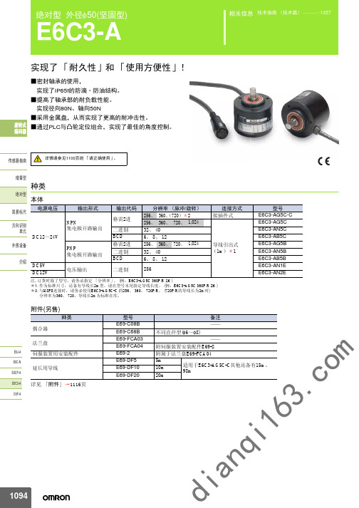
E6C3-A旋转编码器--应用手册--欧姆龙
⊼. ԡⱘ䕧ߎഛЎৠϔಲ䏃DŽ
⊼. ԡⱘ䕧ߎഛЎৠϔಲ䏃DŽ
旋转方向:CW (从轴侧看,为右转)
旋转方向:CW (从轴侧看,为右转) 分辨率/40
No. 1 5 10 15 20 25 30 35 40
Ӵᛳ఼ᣛफ 䞣ൟ 㒱ᇍൟ
输出方式
20 2
1
ON OFF ON OFF ON OFF ON OFF ON OFF
号码No. 1~32 1~40 0~255 0~ 5 0~ 7 0~11 0~255 76~435 (76以上格雷) 152~871 (152以上格雷) 0~1,023
16
因此,旋转超过最高响应转速时,则无法对信号灯进行追踪。 *4. E6C3-AN1E、 -AN2E将旋转方向指定输入(导线 线色・粉)连接到H(VCC)上,可按照CW方向增 加输出码;连接到L(0V)上,可按照CW方向减 120e 少输出码。 E6C3-AN1E:H=1.5~5V、L=0~0.8V E6C3-AN2E:H=2.2~12V、L=0~1.2V 另外,有关-AN1E、 -AN2E,要在LSB(20) 码变化后,达10μs以上,方能读取代码。 *5. JEM1030:1991年适用 *6. 绝对型导线的最小编号地址、轴的 D 切口的位 置电缆引出方向如右图。 120e (输出位置范围:±15°) *7. 分辨率360、 720: 标准导线2m 分辨率256: 标准导线1m
Ӵᛳ఼ᣛफ 䞣ൟ 㒱ᇍൟ ㅔᯧᷛሎ ᮍ䆚߿ ऩܗ ೈ䆒 ҟ㒡
*1. 接通电源时,流过约有 6A 的冲流。 (时间:约 0.8ms) *2. 码如下所示。
输出方式 二进制
3. c
Dߛষ
BCD
分辨率 32 40 256 6 8 12 256 360
autonics旋转编码器中文选型手册及说明书
>4@PUT B ?4@PUT B N4@PUT C D4@PUT C c4@PUT Z C4@PUT Z F4@1V.;VED O;,/ c4@HOE.6V/ yQ@GM H
Nb@f OQO JuI\m@f ul@f
\g.w@f
/; @f m4 /;
Q
PUT B >4 Q
B
PUT C N4 B
C PUT Z c4 C
B2 C2 Z ]J\g.w B2 B2 C2 C2 Z2 Z ]K
.Ogk^8/
Mgn Ib`a
B]<C]4O@fq]S`L
T :
OT >
JTAB]qp1<{K
,*ul @ N[o4 96eB2 [kul @ N[o4 64:VED
,*ul @ N[o4 76eB2 @ful.uzul ;VED/@Nbf4 .uzul3846/VED2 @ful.uzul 7838:VED/@Nbf4 .uzul3946/VED
376 q =6?.RSVBG/2 Pi@38; q >;? 9;q>;,RI2 Pi@ 9;q?6,RI
JQ;6.JFD TC/
@;ee2 ;Q2 by@8e2 yQud.\g.w@@;ee2 >Q/
@<ee TChRK=~
@>ee K=~Jk,K6T>uw=e7
k|4 786`
.\g.w@fgO/
=;6VBD ;65<6Ip 7 *9.EvzE<O^4O/ udhR}:2 l866eeudqhR~hRe
=eLN[o4 :6`_ \e.6466:O e/ 8_eLN[o4 :6`_ \e.6466:O e/ N[o4 :6` \e8 .: =763< c` e8/ X` @ N[o4 8c`_2 =` @ N[o4 7c`_ ;666ihe 76 q ;;Ip1+74;ee X2 Y2 Z2}`|b8 N[o4 ;6H
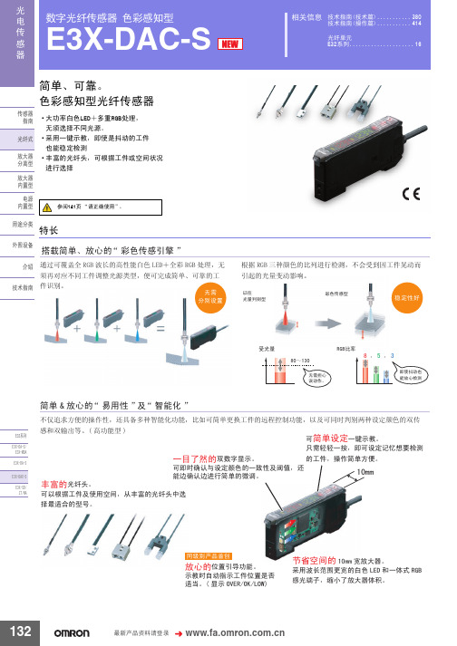
Omron欧姆龙选型样本手册说明书相关信息之数字光纤传感器 色彩感知型E3X-DAC-S
70
E32-D11R/E32-D12R/
E32-D15XR/
42
E32-DC200BR(B4R)
E32-D14LR
11
E32-D15YR/E32-D15ZR
10
E32-D211/E32-DC200E/E32-D22/
E32-D25X/
20
E32-DC200F(F4)
E32-D24
8.8
E32-D25Y/E32-D25Z
ܝ ⬉
数字光纤传感器 色彩感知型
Ӵ ᛳ
E3X-DAC-S
఼
相关信息 技术指南(技术篇) ........... 380
技术指南(操作篇) ........... 414
光纤单元 E32系列 ..................... 16
简单、可靠。 色彩感知型光纤传感器
Ӵᛳ఼ ᣛफ
ܝ㑸ᓣ
ᬒ఼ ߚ行ൟ
乏ݡᇍᑨϡৠᎹӊ䇗ᭈ㉏⑤ܝൟˈ֓ৃᅠ៤ㅔऩǃৃ䴴ⱘᎹ
ӊ䆚߿DŽ
᮴䳔 ߚ߿䆒㕂
ḍ 5*% ϝ辵买㡆ⱘ↨߫䖯㸠Ẕ⌟ˈϡӮফࠄᎹӊᰗࡼ㗠 ᓩ䍋ⱘܝ䞣বࡼᕅડDŽ
ҹᕔ ܝ䞣߸߿ൟ
ᔽ㡆Ӵᛳൟ
〇ᅮᗻད
ফܝ䞣
̚
᮴䳔ᢙᖗ 䇃ࡼDŽ
5*%↨⥛
˖ ˖
ेՓᡪࡼг 㛑ᬒᖗẔ⌟
(㋏߫ (;'$6
-
无电压输入型(有触点/无触点)*3
⬉⑤ 保护电路 ݙ㕂ൟ 防止相互干扰
电源反向连接保护、输出短路保护、输出反向连接保护 最多10台(光通信控制方式)
⫼䗨ߚ㉏ ೈ䆒
ҟ㒡 ᡔᴃᣛफ
响应 时间
超高速模式 *4 高速模式 标准模式 高精度模式
E6C3-A旋转编码器--应用手册--欧姆龙

Ӵᛳ఼ᣛफ 䞣ൟ 㒱ᇍൟ ㅔᯧᷛሎ ᮍ䆚߿ ऩܗ ೈ䆒 ҟ㒡
*1. 接通电源时,流过约有 6A 的冲流。 (时间:约 0.8ms) *2. 码如下所示。
输出方式 二进制
3. c
Dߛষ
BCD
分辨率 32 40 256 6 8 12 256 360
格雷2进 720 1,024
di
an qi
1095
15 16 17 18 19
°
˄H˅ ˄L˅
ᮍ䆚߿ ऩܗ ೈ䆒 ҟ㒡
输出方式
23 2 ×10
0
ƽߚ䕼⥛8ᯊЎ˖ A˙45°ǃ B˙22.5° C˙11.25° ƽߚ䕼⥛6ᯊЎ˖ A˙60°ǃ B˙30° C˙15°
⊼. ԡⱘ䕧ߎഛЎৠϔಲ䏃DŽ
⊼. ԡⱘ䕧ߎഛЎৠϔಲ䏃DŽ
旋转方向:CW (从轴侧看,为右转)
旋转方向:CW (从轴侧看,为右转) 分辨率/40
No. 1 5 10 15 20 25 30 35 40
Ӵᛳ఼ᣛफ 䞣ൟ 㒱ᇍൟ
输出方式
20 2
1
ON OFF ON OFF ON OFF ON OFF ON OFF
φ40
om
E6J-A E6C-N E6CP-A E6C3-A E6F-A
E6C3-A
输入输出段回路图
型号 E6C3-AG5C/-AG5C-C E6C3-AG5B E6C3-AN5C E6C3-AN5B
DC12 ̚24V E6C3-A Џಲ䏃 䕧ߎ 35mAҹϟ DC30V 0V ሣ㬑 GND E6C3-A Џಲ䏃
备注 —— 不同直径型(φ6~φ8) —— 附伺服装置安装配件E69-2 附属于法兰盘E69-FCA04 5m 适用于E6C3-AG5C-C其他还备有15m、 10m 98m 20m
