flow固定器技术特性FUSE-GT
粉末流动性测试仪检测项目及含义

粉末流动性测试仪检测项目及含义
流动性指数是综合休止角、崩溃角、平板角、分散度、松装密度、振实密度等参
数,通过上述测试数据得到差角、压缩度、空隙率、均齐度等指标,还能通过卡尔指数得到流动性指数、喷流性指数等参数获得.
振实密度:振实密度是指粉体装填在特定容器后,对容器进行振动,从而破坏
粉体中的空隙,使粉体处于紧密填充状态后的密度。
通过测量振实密度可以知
道粉体的流动性和空隙率等数据
松装密度:松装密度是指粉体在特定容器中处于自然充满状态后的密度。
该指
标对存储容器和包装袋的设计很重要
休止角:粉体堆积层的自由表面在静平衡状态下,与水平面形成的最大角度叫
做休止角。
它是通过特定方式使粉体自然下落到特定平台上形成的。
休止角对
粉体的流动性影响最大,休止角越小,粉体的流动性越好。
休止角也称安息角、自然坡度角等。
崩溃角:给测量休止角的堆积粉体以一定的冲击,使其表面崩溃后圆锥体的底
角称为崩溃角。
平板角:将埋在粉体中的平板向上垂直提起,粉体在平板上的自由表面(斜面)和平板之间的夹角与受到震动后的夹角的平均值称为平板角。
在实际测量过程中,平板角是以平板提起后的角度和平板受到冲击后除掉不稳定粉体的角度的
平均值来表示的。
平板角越小粉体的流动性越强。
一般地,平板角大于休止角。
分散度:粉体在空气中分散的难易程度称为分散度。
测量方法是将 10 克试样从一定高度落下后,测量接料盘外试样占试样总量的百分数。
分散度与试样的分
散性、漂浮性和飞溅性有关。
如果分散度超过 50%,说明该样品具有很强的飞溅倾向。
如何使用保险丝

0.003~ 3 Sec 0.02 Sec(ma)
FUSING Basics: Hot spot
温度 Temperature(°C)
Melting Point
I >In In
PCB Sn 錫球 負載電流時的溫度 PCB
Basic Fusing Process
1000
100
• •
TIME IN SECONDS
10
1
0.6
0.1
0.01
10A
0.1
1 10 100 1000 CURRENT IN AMPS
UL/CSA248-1/14規格 V.S IEC60127規格
額定電流(%) 100% 135% 150% 200% 210% 275% 400% 1000% UL&CSA STD 248-1/14 4hr (min) 60 minute (max) ----2 minute (max) ----------------IEC 60127 Sheet 1 --------60 minute (min) ----30 minute (max)
Cat. Fuse Rating =1.91A (最小能選擇的安培數) [計算值]-Absolute minimum fuse rating can be selected. (1206 size 的466 or 468系列2A 以上安培數, 請參考表(一)。) 表 (一)
Catalog Number Ampere Rating Making Code Voltage Rating Nominal Resistance Cold Ohms Melting I t(A2Sec.)2
模具用

地角螺栓
angle shearing machine
角材剪切机
decoiling device / uncoiler
safe load
安全载重
safety cover / safety guard / debris guard
安全罩
safety control
安全管理
safety clearance
油みぞ
oil groove
油焼き入れ
oil quenching / oil hardening
油を取り除く
de-grease
あふれ
overflow
粗い
rough
あらかじめ圧縮応力を与える pre-stressed
Chinese 压入 压入冲压机 上部工作台
厚度 压力 压力计 压力源 压力中心 压力加油 压力调整块
糸面取り
small chamfer
铸件减重
鋳抜
鋳抜穴 鋳肌面の粗度
cast out / notched hole / core /core pocket / cored opening
铸件减重孔
cast in hole / core / cored hole
铸件表面粗糙度
molding finish
pressure lubrication
圧力調整ブロック
a block to adjust pressure
圧力調整弁
pressure regulating valve / pressure regulator valve
圧力パッド
pressure pad
圧力比
pressure ratio
当て板
Leica CM3050 S 冷冻切片机 使用说明书 中文版
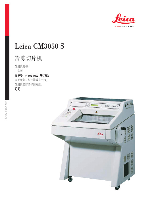
Leica CM3050 S
3
目录
1. 重要信息 ............................................................................................................................................... 7
陈述、图画、插图和其他关于当前使用说明书的内容或技术细节的信息不视为我们产品的保证 特征。
保证特征仅由我们和我们的客户之间达成的合同条款确定。
徕卡公司保留在不另行通知的情况下更改技术规格和制造工艺的权利。只有这样,才有可能不 断提高我们的产品采用的技术和制造技艺。
本文档受著作权法保护。本文档一切版权均属于 Leica Biosystems Nussloch GmbH 所有。
Leica CM3050 S
冷冻切片机
使用说明书 中文版 订单号:14 0443 89102 - 修订版 O 本手册务必与仪器放在一起, 使用仪器前请仔细阅读。
版本 2.5,修订版 O - 11.2021
医疗器械备案凭证编号/产品技术要求编号:国械备20180127号 备案人/生产企业英文名称:Leica Biosystems Nussloch GmbH 备案人/生产企业中文名称:徕卡生物系统(努斯洛赫)有限公司 住所:Heidelberger Strasse 17-19, 69226 Nussloch, Germany 生产地址:Heidelberger Strasse 17-19, 69226 Nussloch, Germany 联系方式: 生产日期:见产品中文铭牌 代理人/售后服务单位:徕卡显微系统(上海)贸易有限公司 住所:中国(上海)自由贸易试验区富特北路127号3楼C部位 联系电话:4006580692
FLOWMASTER2船舶领域应用介绍

FLOWMASTER2在船舶领域的应用北京海基科技有限公司2004年5月目录1. 软件基本介绍 (2)1.1 FLOWMASTER2开发商简介 (2)1.2 FLOWMASTER2软件介绍 (2)1.2.1 可视化建模 (2)1.2.2 仿真分析 (4)1.2.3结果分析以及后处理 (6)1.2.4元件库 (6)1.2.5数据库管理 (6)1.3 FLOWMASTER2软件接口 (7)1.3.1 FLOWMASTER2与其他仿真工具的接口 (7)1.3.2 FLOWMASTER2与CAD工具的接口CADLink工具包 (8)1.4 FLOWMASTER2对电信号与机械信号的仿真与模拟 (8)2. FLOMWASTER2软件的优点 (9)3. FLOWMASTER2在船舶领域的应用 (10)3.1空调系统 (11)3.2 船舶发动机冷却系统 (12)3.3 消防系统 (13)3.4 润滑系统 (14)3.5 压舱进排水系统 (15)3.6 供油系统 (16)4. FLOWMASTER2硬件及操作系统配置要求 (17)5. 购买软件以后技术服务的内容、时间、方式 (18)6. FLOWMASTER2培训 (18)7. 软件的升级情况 (19)8. 软件交付的形式、license的管理方式以及验收内容 (19)9. FLOWMASTER2船舶客户列表 (19)1. 软件基本介绍随着计算机技术的进步,利用软件仿真已是工程技术,尤其是CAE发展的趋势。
利用目前世界领先的流体系统仿真工具FLOWMASTER2,工程师能够将更多的精力集中在系统的设计上。
无论是设计产品的水/液系统、油、气(空气、氧气、二氧化碳、氢气等)系统,FLOWMASTER2都可以对系统进行精确的压力、流量、流速、温度分析。
它可以帮助企业减少生产成本,提高产品性能,缩减产品开发时间和试验次数,提高实验设计质量。
FLOWMASTER2是一个成熟的仿真软件,其设计思路合理,软件技术先进,易熟练掌握,完全有能力仿真各种流体管网系统。
流式细胞仪检测细胞凋亡操作流程 - BrdU Flow Kits 检测细胞增殖
B r d U F l o w K i t s检测细胞增殖实验原理BrdU中文全名5-溴脱氧尿嘧啶核苷,为胸腺嘧啶的衍生物,可代替胸腺嘧啶在DNA合成期(S期),活体注射或细胞培养加入,而后利用抗Brdu 单克隆抗体,荧光染色,显示增殖细胞。
同时结合其它细胞标记物,可判断增殖细胞的种类,增殖速度,对研究细胞动力学有重要意义。
BrdU Flow Kits是用BrdU 染色和流式分析结合高效的试剂盒,包括在BrdU 存在下培养细胞,以适宜浓度的DNA 酶使胞内DNA 变性,加强掺入BrdU 与抗体的亲和力,同时保留胞内蛋白结构和荧光素荧光强度,从而避免了DNA 变性条件与胞内及表面标志同时检测条件的冲突,运用荧光标记的抗细胞表面抗原单抗及抗细胞因子单抗,结合固定、破膜、通透等处理技术使同时检测细胞活化、增殖、DNA 合成及胞内细胞因子的分泌成为可能。
7-AAD染色总DNA,通过BrdU和7-AAD双色染色就能刻画中细胞在整个细胞周期中增殖时期的特点。
BrdU Flow Kits 试剂盒FITC BrdU Flow KitCat. No. 559619 (50 tests) Cat. No. 557891 (4×50 tests)APC BrdU Flow KitCat. No. 552598 (50 tests) Cat. No. 557892 (4×50 tests)1.抗BrdU荧光抗体每管50μl 染色50 样本(106 cells/样本). FITC BrdU Flow Kit(Cat. No. 559619) 包含50μl FITC anti-BrdU抗体。
APC BrdU Flow Kit (Cat. No.552598), 包含50 μl APC anti-BrdU抗体。
抗体使用前用BD Perm/Wash Buffer按照1:50稀释。
每个样本加入50 μl 稀释抗体。
FLOW单板的技术特点图列(快穿固定器)

Reflex木芯 Flow最轻,最灵敏的木芯,带给人类已知的最高强度-重量比的木芯结构。
在你所需要的区域侧重响应性,特定区域使用更多中低密度木芯,在增加强度的同时减轻重量。
皇家威士忌使用玻璃纤维的全新剪裁,好处就是消除了固定器脚跟和脚尖的区域的抖动。
增加了边刃控制力并提供流畅平顺的滑行。
枪手威士忌一种反V字型设计,使用4条炭纤维实现疯狂的弹性,同时让板头、板尾不受约束,拥有轻快和灵活的滑行感觉。
双轴纤维(0/90度)大部份纤维在0度轴上,用于增加额外的弹性和使雪板拥有更自然的扭力弹性。
OPTIX 2000 快速并少维护。
EZDT(E-DT)边刃为EZ-Rock和另一个版本的EZFlat-Rock设计,EZDT在固定器和板头之间是一条小弧度的边刃,在固定器区域是更加积极抓地的边刃。
这样更加容易上手滑行,同时混合的大弧度刃也可以做出快速的换刃。
纯双向板头板尾的距离相等,使滑行在任何方向滑行都有相同的感觉。
单向板头比板尾略长,固定器安装孔后置,板尾跳跃会获得更多的弹性,更好的野雪漂浮。
3DT(3D-过渡)边刃平顺并拥有的宽泛的抓地能力,3D过渡边刃的混合方式很与众不同,两脚之间弧度小的是为I-Rock,弧度超大的是为了采用Pop-Cam的雪板。
小弧度板头和固定器区域较大的弧度提供一个无限的抓地性,具综合性的超平顺和轻快的滑行感觉。
摇椅传送带一条炭纤维带子水平的放置在木芯下面,在每款摇椅雪板上创造出一个轻微凸起的板底。
从上铁杆儿到呲铁杆滑行都变得更平顺了。
摇滚威士忌位于脚跟和脚尖下面的4片玄武岩薄片直接将滑手的能量传递到雪板上的关键控制区域。
同时也使强度和全地形的边刃控制得到加倍,并且不会影响到滑行的平顺。
I-ROCK 摇椅凸起板底的摇椅拱形在铁杆上更自然的感觉,在多边的情况下也能保持稳定。
在固定器区域的外侧结合了反弓,I-ROCK提供了稳定和反弓的弹性,使之拥有了从高山到公园的性能。
EZ-ROCK 固定器之间超微小的凸起摇椅板底和固定器区域外侧反弓提供了独一无二的稳定。
FS-2 Paddle Flow Switch规格和使用说明书

SPECIFICATIONSService: Compatible liquids. Wetted Materials: Bellow: Tin-bronze;Vane: Stainless Steel;Body: Forged brass.Temperature Limit: 230ºF (110ºC).Pressure Limit: 145 psig (10 bar).Enclosure Rating: IP64.Switch Type: SPDT snap switch.Electrical Rating: 10A res, 3A ind @ 250 VAC.Electrical Connection: Cable gland with attached wire leads.Process Connection: 1˝ male NPT.Mounting Orientation: Switch must be installed vertically on horizontal pipe runs.Set Point Adjustment: Four vane combinations and an adjustment screw.Enclosure: Die-cast aluminum alloy.Weight: 28.22 oz (0.8 kg).Agency Approvals:CE.Electrical ConnectionsConnect wire leads in accordance with local electrical codes and switch action required. N.O. contact will close and N.C. contact will open when flow increases to the actuation point. They will return to “normal” condition when flow decreases to the deactuation point. Brown = Common, Blue = Normally Open, Black = Normally Closed, and Yellow/Green = Earth Ground.5-1/8The Model FS-2 Paddle Flow Switch offers an economical flow proving solution.Custom set points tailored for the application are enabled by field adjustable vane layers and a set point adjustment screw. The FS-2 features an aluminum weatherproof housing for outdoor installation. Paddles are adjustable to fit 1˝ to 8˝size pipe. FS-2 is ideal for use in “flow or no flow” applications in cold and hot water systems.FEATURES•Field Adjustable Paddle • Field Adjustable Set Point • Weatherproof ConstructionINSTALLATIONUnpack and remove any packing material found in the lower housing. Install in piping with the arrow pointing in the direction of flow. The switch must be installed vertically on horizontal pipe runs. To ensure a steady working flow, make certain to keep the paddle flow switch a safe distance from sources of turbulence such as elbows, valves, pumps, etc. The recommended minimum distance upstream and downstream of the flow switch is about 5 times the pipe’s diameter.Note : When installed, make sure that the vane has full range of motion and is not hindered by contacting the wall of a pipe, bushing, or tee.Figure 1©Copyright 2014 Dwyer Instruments, Inc.Printed in U.S.A. 9/14FR# R5-443380-00 Rev. 1Once you have the correct vane length, you can then adjust the flow rate setting by means of the adjustable bolt shown in Figure 2. Fully tighten the adjustable bolt to obtain the minimum flow rate setting. Fully loosen the adjustable bolt to obtain the maximum flow rate setting. The adjustable bolt can be adjusted and set according to practical requirements. See Table 1 for the limiting flow rate settings in relation to the pipe diameter and blade length.Note : The Model FS-2 is shipped with the adjustable bolt fully tightened, in the minimum setting. Also, the pre-set bolt shown in Figure 2 has been adjusted before leaving the factory. Users should not adjust this by themselves. Adjustment of thepre-set bolt could lead to switch malfunction and possibly void the warranty.Figure 2: AdjustmentMAINTENANCEInspect and clean wetted parts at regular intervals. The cover should be in place at all times to protect the internal components from dirt, dust, and weather.Disconnect the device from the supply circuit before opening to prevent ignition of hazardous atmosphere.The Model FS-2 Paddle Flow Switch is not field serviceable and should be returned if repair is needed (field repair should not be attempted and may void warranty). Be sure to include a brief description of the problem plus any relevant application notes. Contact customer service to receive a return goods authorization number before shipping.ADJUSTMENT OF FLOW RATE SETTINGDetermine the correct blade length, which is based on the size of your pipe (see Table 1). Remove only those layers which are too long. Leave the smaller layers on to reinforce the vane. To remove vane layers, proceed as follows:a.Remove the screw and lockwasher holding the layers together. Do not losethese parts.b. Remove the unwanted layers.c. Resecure the vane with the original screw and lockwasher.d. With a hammer, lightly peen the end of the screw so that it can not back out.e. If you lose the screw or lockwasher, do not replace with other parts which maycorrode and break. That will void the warranty and might cause severe damage to equipment located downstream of the switch.Pipe Diameter (inch)11-1/41-1/222-1/234568Blade Length in (mm)Dim. X 1.34 (34)1.34 (34)2.24 (57)2.24 (57)3.46 (88)3.46 (88)3.46 (88)6.57 (167)6.57 (167)6.57 (167)Approximate Actuation and DeactuationFlow Rates for Water Minimum SettingGPM (LPM)Maximum Setting GPM (LPM)Actuate 4.0 (15.0)5.3 (20.0)7.0 (26.7)14.1 (53.3)18.5 (70.0)27.7 (105.0)59.4 (225.0)52.8 (200.0)75.7 (286.7)184.9 (700.0)Actuate 8.8 (33.3)11.4 (43.3)14.5 (55.0)31.3 (118.3)35.2 (133.3)52.8 (200.0)123.3 (466.7)132.1 (500.0)154.1 (583.3)396.3 (1500.0)Deactuate 1.8 (6.7)2.6 (10.0)4.0 (15.0)9.7 (36.7)15.4 (58.3)25.1 (95.0)52.8 (200.0)39.6 (150.0)52.8 (200.0)158.5 (600.0)Deactuate6.6 (25.0)8.4 (31.7)11.4 (43.3)22.5 (85.0)30.8 (116.7)46.2 (175.0)114.5 (433.3)123.3 (466.7)140.9 (533.3)374.2 (1416.7)TABLE 1: FLOW RATE CHART。
Flow-Tech PTFE Flow Meters FLD1000 FLD2000 产品说明书

B1-21Incorporando a tradicional tecnologiade vidro de precisão de área variável, estes medidores de fluxo robustos de PTFE oferecem soluções precisas e econômicas para medições de fluxo de intervalo médio.FLD1000/FLD2000 são projetados com escalas únicas giratórias de leitura direta dupla de ar-água com graduações mostrando marcações de SCFM e SLPM (ar), assim como marcações de GPM e LPM (água).Os medidores de fluxo são testados individualmente no Detector de Vazamento do Espectômetro de Massa e certificado para uma classificação de integridade de vazamento de hélio de 1 x 10⁻⁷ SCCS ou melhor.242,57(9,0)283,46(11,16)175,26(6,90)5,309(2,09)51,82(2,04)12,55(0,49)133,60(5,26)3/8-18 NPT (2 PLS)1-18 UNS 2AMontagem de Painel de PTFE Série FLD2200104,85(4,01)47,49(1,87)3/8-18 FNPT175,26(6,90)269,24(10,36)54,10(2,13)Dimensões: mm (polegadas)FLD2201 mostrado em escala menor que a real.PTFE Vertical Na LinhaSérie FLD1200U E strutura Rígida e Compacta U E scalas Duplas,Giratórias e de Leitura Direta para Ar e Água U G raduações Refletem os Sistemas Métrico e Inglês U M onta gem Vertica l Na Linha ou No PainelSérie FLD1000/FLD2000ROTÂMETROS DE LEITURA DIRETA EM LINHA E DE PAINEL19,05(0,75)B1-22ESPECIFICAÇÕESExatidão: +5% de fundo de escala Temperatura Máxima:65°C (150°F) ou 121°C (250°F) para unidade do 3160 em aço inoxidável ou em latão Pressão Máxima: C orpo de Metal : 10.3 bar (150 psig)@ 93°C (200°F) C orpo PTFE: 6.7 bar (100 psig) @ temperatura ambienteÉ fornecido com manual de utilização completo.Para limpeza por oxigênio, acrescente o sufixo “-O2CLEAN” para o número do modelo, a um custo adicional.Calibração rastreável NIST não disponível.Exemplo de pedido: FLD2101, medidor de fluxo de leitura direta de latão com válvula.FL1101 medidor de fluxo vertical na linha de leitura direta de latão com válvula.Conexões: 3⁄8 NPT fêmea em linha ou horizontal traseiroEscalas: Giratórias, leitura direta do ar (SCFM-SLPM) e água (GPM-LPM). O comprimento nominal da escala é de 127 mm (5")Integridade de vazamento: testados individualmente contra vazamentos e certificadosBlindagens do tubo: policarbonatoTubos de vazão: Vidro de borosilicato de parede pesada formado com precisãoFlutuadores: PTFE para PTFE3, 316 em aço inoxidável para unidades de 316 em aço inoxidável e em latãoPartes Úmidas: PTFE, latão ou 316 em aço inoxidávelSelos: PTFE; FKM para unidades de 316 em aço inoxidável e em latão4,1 16。
滑雪板固定器种类-概述说明以及解释

滑雪板固定器种类-概述说明以及解释1.引言1.1 概述滑雪板固定器是一种安装在滑雪板上的设备,用于确保滑雪板与鞋子之间的牢固连接。
它起到了固定和控制滑雪板的重要作用,对于滑雪者的安全和滑雪体验起着至关重要的作用。
在滑雪运动中,滑雪板固定器的选择对于滑雪者的表现和滑雪的舒适程度至关重要。
不同种类的固定器具有不同的特点和功能,以适应不同滑雪场地和滑雪者的需求。
本文将重点介绍三种主要类型的滑雪板固定器。
首先,我们将详细讨论第一种固定器的特点、优点和缺点,然后转到第二种和第三种固定器。
通过对这些不同类型的固定器的详细分析,我们将为滑雪者提供选择合适滑雪板固定器的指导。
在整篇文章中,我们将通过对不同固定器的特点和功能进行分析,以及对其优点和缺点的评估,为滑雪者提供一个全面的了解。
通过对这些信息的了解,滑雪者将能够选择最适合他们需求和技能水平的固定器,从而提高他们的滑雪体验和安全性。
综上所述,本篇文章将通过对滑雪板固定器的各种类型和特点的介绍,为读者提供一个全面深入的了解。
接下来的章节将更加详细地探讨每种固定器的特点、优点和缺点,以帮助滑雪者做出明智的选择。
1.2 文章结构文章结构部分的内容可以如下所示:文章结构:本文将围绕滑雪板固定器的种类展开讨论。
首先,我们将在引言部分概述整篇文章的内容概况。
然后,我们将进入正文部分,分为三个章节,分别介绍三种不同的固定器。
每个章节将包含该种固定器的特点、优点和缺点的详细解析。
最后,在结论部分,我们将对每种固定器进行总结,总结其特点、优点和缺点。
通过这样的结构安排,我们将能够全面了解滑雪板固定器这一主题。
首先,引言部分将为读者提供整篇文章的大致框架和目的。
然后,在正文部分,我们将详细介绍每一种固定器的特点、优点和缺点,为读者提供全面的了解和评估。
最后,在结论部分,我们将对整篇文章进行总结,帮助读者对不同种类的固定器有更深入的理解。
这样的结构安排将有助于读者系统地了解各种固定器的特点和优缺点,为选择合适的滑雪板固定器提供参考和指导。
心表组织固定器产品技术要求ruikewo
心表组织固定器适用范围:适用于接受非体外循环下冠状动脉旁路移植术患者。
1.1 产品型号:心表固定器:02-0101、02-0102、02-010302-0201、02-0202、02-0203A、02-0203B02-0300A、02-0300B、02-0301、02-0302A、02-0302B、02-030302-01.01A、02-01.01B、02-01.02、02-01.03A、02-01.03B、02-01.0402-02.02、02-02.03附件:010101、010201、010301、010302、010501、010601、010602020101、020201、020301、020302、020401、0204021.2 产品结构及组成:1.2.1心表组织固定器由调节手柄、固定卡座、连接臂、固定盘(吸盘和压盘2种类型)、吸引延长管五部分组成。
1.2.2固定器附件包装形式分别为,单独包装、装配固定器后包装。
1.3材质1.3.1金属部分主要采用0Cr18Ni9Ti、102Cr17Mo、1Cr18Ni9Ti、20Cr13、40Cr13;1.3.2塑料部分高分子材料主要采用聚酰亚胺(PEI)、聚氨酯(TPU)、聚碳酸酯(PC)、硅胶;1.3.3吸引延长管内径Φ6.5mm,长度大于2000mm,PVC塑料管(带“*”号标识的不配吸引延长管)。
2.1外观2.1.1目测固定器及附件外观应规整、色泽均匀,无明显划痕、破损及变形等缺陷。
2.1.2操作观查固定器各组件之间应配合良好,连接紧密,活动自如,万向关节臂应活动自如,附件应装配顺畅无卡塞现象。
2.2性能2.2.1主要尺寸:见附录A2.2.2稳定性:2.2.2.1连接臂顺时针旋转调节手柄锁紧,使连接臂承受20N的负载,各关节应无明显活动;2.2.2.2“U”形吸盘打开负压(200-400mmHg),将连接臂的“U”形吸盘调节到动物心脏表面位置,顺时针旋转调节手柄锁紧, U形吸盘与接触面吸附。
Flowline垂直浮力液位开关LV10系列说明书
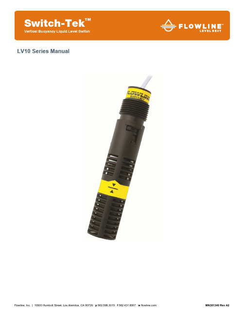
Flowline, Inc. | 10500 Humbolt Street, Los Alamitos, CA 90720 p 562.598.3015 f 562.431.8507 w MN301340 Rev A2LV10 Series ManualIntroduction / Table of Contents Step One ABOUT SWITCH-TEK™ VERTICAL BUOYANCY LEVEL SWITCHThe Vertical Buoyancy Switch consists of a float, magnet reed switch and baffle body which dampens turbulence and eliminates the negative effects of switch chatter. When the probe is dry, the float rests on the bottom of the baffle body such that the magnet does not influence the reed switch. As the probe becomes immersed in liquid, the float becomes buoyant and the magnet elevates causing the reed switch to change to change.TABLE OF CONTENTSSpecifications: (3)Dimensions: (3)Safety Precautions: (4)Installation: (5)Top Wall Installation: (5)Bayonet Connection: (5)Orientation: (5)Connection to a Switch Car Kit (LM30 series):: (6)Electrical: (7)Smart Trak and Switch Pak Assemblies: (7)Wiring: (8)Wiring to a Flowline Controller: (8)Maintenance: (9)Warranty: .................. .. (10)|2MN301340 Rev A2MN301340 Rev A2 3 |Specifications / DimensionsStep TwoAccuracy:±2mm in water Repeatability: ±1mm in water Orientation:±20˚ from vertical Specific Gravity: 0.8 minimum Contact Type: (1) SPDT reed Contact Rating: 15VA, 0.25A max.Contact Voltage: 120 VAC, 120 VDC @ 15 VA Contact Output: Selectable NO/NCCE Rating:30 Vrms and 42.4 Vpeak or 60 VDC @ 15 VATemperature Range: F: -40˚ to 176˚ C: -40˚ to 80˚ Pressure Range: 25 psi (2 bar) @ 25˚ C., derated@ 1.667 psi (.115 bar) per ˚C. above 25˚ C.Sensor Rating: NEMA 6 / IP68 Sensor Material: Polypropylene (PP) Polyvinylidene Fluoride (PVDF) Cable Type: 3-conductor, 22-gauge,shieldedCable Length: 10’ (3m) Cable Material: PP or FEP jacket Mounting Threads: 3/4” NPT (3/4” R) CE Compliance: EN 61326 EMC EN 61010-1 safetySwitch Rating Reed SwitchRating Maximum Resistive LoadVA Volts Amps AC Amps DC 15 0-50 0.3 0.21 15 120 0.13 0.09 15 2400.06 0.04ComponentsPartNumber Body Material Cable Material Thread LV10-1301 PP PP ¾” NPT LV10-1351 PP PP ¾”R LV10-5301 PVDF FEP ¾” NPT LV10-5351 PVDF FEP¾” RPressure / Temperature DeratingDIMENSIONSLV10-1301, LV10-1351, LV10-5301, LV10-5351Safety Precautions Step ThreeAbout Manual: PLEASE READ THE ENTIRE MANUAL PRIOR TO INSTALLING OR USING THISPRODUCT. This manual includes information on the vertical buoyancy, model LV10-_3_1. Please refer tothe part number located on the sensor label to verify the exact model which you have purchased.User’s Responsibility for Safety: Flowline manufactures a wide range of liquid level switches andtechnologies. While each of the these switches are designed to operate in a wide variety of applications, it is the user’s responsibility to select a switch model that is appropriate for the application, install it properly, perform tests of the installed system, and maintain all components. The failure to do so could result in property damage or serious injury.Proper Installation and Handling: Because this is an electrically operated device, only properly trained staff should install and/or repair this product. Use a proper sealant with all installations. Never over tighten the sensor within the fitting, beyond a maximum of 80 inch-pounds torque. Always check for leaks prior tosystem start-up.Material Compatibility: The LV10 level switch is available in two wetted material versions. The switch and the cable jacket are made of Polypropylene (PP) for the LV10-13_1. The switch is made ofPolyvinylidene Fluoride (PVDF) and cable jacket is made of Fluorinated Ethylene Propylene (FEP) for the LV10-53_1. Make sure that the switch is compatible with the application liquids. To determine thechemical compatibility between the sensor and its application liquids, refer to the Compass CorrosionGuide, available from Compass Publications.Temperature and Pressure: The LV10 series switch is designed for use in application temperatures up to 80˚C,andforuseatpressuresupto25psi(2bar)@25˚C.,****************(.115bar)per˚C.above25˚C.Wiring and Electrical: The supply voltage used for the LV10 switch should never exceed 120 volts AC @15 VA for the LV10-_3_1. For CE applications, the supply voltage for the LV10 switch should never exceed30 VRMS and 42.4 Vpeak or 60 VDC. Electrical wiring of the switch should be performed in accordancewith all applicable national, state, and local codes.Flammable, Explosive and Hazardous Applications: The LV10 series switch should not be used within flammable or explosive applications unless properly connected to a approved control device. In hazardous applications, use redundant measurement and control points, each having a different sensing technology.Refer to the National Electrical Code (NEC) for all applicable installation requirements in hazardouslocations.WarningAvoid installing the LV10 in magnetized metal tanks. Doing so will activate the internal reed switch.|4MN301340 Rev A2TOP WALL INSTALLATIONFLOWLINE’s LV10 switch may be installed through the top wall of a tank. For Smart Trak (LM10 series) installations, remove the sensors thread and use the bayonet adapter to interface to the LM30 series Switch Car. For Switch Pak™ (LM45 series) installations, use the 3/4” thread as the interface.Bayonet Connection: The ¾” thread can be removed to access the bayonet connection. Simple press down on the threads and twist to release. Orientation: Mounting orientation bust be kept vertical for proper orientation. The vertical buoyancy and float switches are orientated in vertical position ±20˚.MN301340 Rev A2 5 |CONNECTION TO A SWITCH CAR KIT (LM30 SERIES)In order to attach the LV10 series to a Smart Trak (LM10 series) fitting, a Switch Car Kit (LM30 series) is required. The LV10 series can be attached in two ways, without the bayonet adapter and with the bayonet adapter.Without Bayonet Adapter With Bayonet AdapterThe use of the bayonet adapter will increase the overall length of the LV10/LM30 series assembly. This will result in a lower activation point within the tank due to the added length. It is recommended to remove the bayonet adapter when interfacing with Smart Trak.First, remove the bayonet adapter by pressing down twisting the adapter. Next, thread the sensor wire through the O-ring and the sensor car and out through the hole between the sensor car shoe and the locking bolt. Set the O-ring into theLV10. Push the sensor into the bayonet side of sensor car. Screw the bayonet adapter onto the sensor until the sensor seats against the pit inside the adapter.|6MN301340 Rev A2MN301340 Rev A27 |ElectricalStep SixVOLTAGEThe input voltage to the LV10 switch should never exceed the maximum voltage rating. FLOWLINE controllers have a built-in 13.5 VDC power supply which provides power to all of FLOWLINE’s level switches. Alternate controllers and power supplies may also be used with the LV10 switch.CABLE LENGTHDetermine the length of cable required between the LV10 series sensor and its point of termination. Allowenough slack to ensure the easy installation, removal and/or maintenance of the sensor. The cable length may be extended up to a maximum of 1000 feet, using a well insulated, shielded wire.WIRE STRIPPINGUsing a 10 gauge wire stripper, carefully remove the outer layer of insulation from the last 1-1/4” of thesensor’s cable. Unwrap and discard the exposed foil shield from around the signal wires, leaving the drain wire attached if desired. With a 20 gauge wire striper, remove the last 1/4" of the colored insulation from the signal wires.SMART TRAK AND SWITCH PAK ASSEMBLIESThe Vertical Buoyancy Level Switch can be packaged with Flowline Smart Trak or Switch Pak assembly.Smart Trak with Compact Relay ControllerAV23-4313, AV23-4323, AV23-4317 or AV23-4327 All models use (2) LV10-13_1 switchesSwitch-Pak with Compact Junction BoxAV16-4243, AV16-4247, AV16-5243 or AV16-5247 All models will use (1) LV10-_3_1 switchSmart Trak with Compact Relay Controller AV16-4343/AV16-4347 – Uses (1) LV10-13_1 AV26-4343/AV26-4347 – Uses (2) LV10-13_1 AV36-4343/AV36-4347 – Uses (3) LV10-13_1 AV46-4343/AV46-4347 – Uses (4) LV10-13_1 Switch-Pak with Compact Relay Controller AV13-4213, AV13-4217, AV13-4223, AV13-4227, AV13-5213, AV13-5217, AV13-5223 or AV13-5227 All models will use (1) LV10-_3_1 switch| 8 MN301340 Rev A2WiringStep SevenWIRING TO A FLOWLINE CONTROLLERLC40 Series Controller (LC42-1001 Shown) LC10/LC11 Series Controller (LC11-1001 Shown)NOTE: When using a latching relay, the polarity of both switches must be the same. Either both switches are wired Normally Closed (Red & Black – See Relay #2 with LC42) or both Normally Open (White & Black – See Relay #1 with LC11).VERTICAL BUOYANCY LEVEL SWITCH (LV10-_3_1)The LV10-_3_1 switch can be wired normally open or normally closed for your application requires. Normally OpenUse the Black and White wire for operation the LV10-_3_1 in a normally open state. Normally open isdefined as the switch being open when the float is dry and closed when the float becomes submersed. This operation is typical for indicating a high level. Normally ClosedUse the Black and Red wires for operating the LV10-_3_1 in a normally closed state. Normally closed is defined as the switch being closed when the float is dry and open when the float becomes submersed. This operation is typical for indicating a low level.Maintenance Step Eight GENERALWhile a filter should protect the float from particulate contamination, the switch may need to be cleaned periodically to prevent jamming of sticking. The vertical buoyancy and vertical float has no scheduled maintenance requirement, except to clean off any deposits or scaling from the switch as necessary. It is the responsibility of the user to determine the appropriate maintenance schedule, based on the specific characteristics of the application liquid.CLEANING PROCEDURE1. Power: Make sure that all power to the switch, controller and/or power supply is completelydisconnected.2. Switch removal: If necessary, make sure that the tank is drained well below the switch prior toremoval. Carefully, remove the sensor from the installation. Remove the outer screen by pushing on the screen and turning it slightly to disconnect it from the buoyancy net connector so that the float isexposed.3. Cleaning the switch: using a soft bristle brush and mild detergent, carefully wash the switch. Do notuse harsh abrasives such as steel wool or sandpaper, which might damage the surface of the sensor.Do not use incompatible solvents which may damage the sensor’s PP or PVDF plastic body. Takeparticular care to remove any scaling from the float body and make sure that it moves freely.4. Sensor installation: Follow the appropriate steps of installation as outlined in the Installation section ofthis manual.TESTING THE INSTALLATION1. Power: Turn on power to the controller and/or power supply.2. Immersing the switch: Immerse the sensing tip in its application liquid, by filling the tank up to theswitch. An alternative method of immersing the switch during preliminary testing is to hold a cup filled application liquid up to the switch’s tip.3. Test: With the switch being fluctuated between wet and dry states, the switch indicator light in thecontroller should turn on and off. If the controller doesn’t have an input indicator,a. Use a voltmeter with a power supply in series to measure an open or closed circuit.b. Use an ohmmeter in series to measure an open or closed circuit.4. Point of actuation: Observe the point at which the rising or falling fluid level causes the switch tochange state, and adjust the installation of the switch if necessary.EXAMPLETesting the LV10 series with a Multimeter set to read Volts. When wired NO (Black and White), the meter willread 0 volts when dry and full voltage when wet.MN301340 Rev A2 9 |Warranty, Returns and Limitations Step TenWARRANTYFlowline warrants to the original purchaser of its products that such products will be free from defects in material and workmanship under normal use and service in accordance with instructions furnished by Flowline for a period of two years from the date of manufacture of such products. Flowline's obligation under this warranty is solely and exclusively limited to the repair or replacement, at Flowline's option, of the products or components, which Flowline's examination determines to its satisfaction to be defective in material or workmanship within the warranty period. Flowline must be notified pursuant to the instructions below of any claim under this warranty within thirty (30) days of any claimed lack of conformity of the product. Any product repaired under this warranty will be warranted only for the remainder of the original warranty period. Any product provided as a replacement under this warranty will be warranted for the full two years from the date of manufacture.RETURNSProducts cannot be returned to Flowline without Flowline's prior authorization. To return a product that is thought to be defective, go to , and submit a customer return (MRA) request form and follow the instructions therein. All warranty and non-warranty product returns to Flowline must be shipped prepaid and insured. Flowline will not be responsible for any products lost or damaged in shipment.LIMITATIONSThis warranty does not apply to products which: 1) are beyond the warranty period or are products for which the original purchaser does not follow the warranty procedures outlined above; 2) have been subjected to electrical, mechanical or chemical damage due to improper, accidental or negligent use; 3) have been modified or altered; 4) anyone other than service personnel authorized by Flowline have attempted to repair; 5) have been involved in accidents or natural disasters; or 6) are damaged during return shipment to Flowline. Flowline reserves the right to unilaterally waive this warranty and dispose of any product returned to Flowline where: 1) there is evidence of a potentially hazardous material present with the product; or 2) the product has remained unclaimed at Flowline for more than 30 days after Flowline has dutifully requested disposition. This warranty contains the sole express warranty made by Flowline in connection with its products. ALL IMPLIED WARRANTIES, INCLUDING WITHOUT LIMITATION, THE WARRANTIES OF MERCHANTABILITY AND FITNESS FOR A PARTICULAR PURPOSE, ARE EXPRESSLY DISCLAIMED. The remedies of repair or replacement as stated above are the exclusive remedies for the breach of this warranty. IN NO EVENT SHALL FLOWLINE BE LIABLE FOR ANY INCIDENTAL OR CONSEQUENTIAL DAMAGES OF ANY KIND INCLUDING PERSONAL OR REAL PROPERTY OR FOR INJURY TO ANY PERSON. THIS WARRANTY CONSTITUTES THE FINAL, COMPLETE AND EXCLUSIVE STATEMENT OF WARRANTY TERMS AND NO PERSON IS AUTHORIZED TO MAKE ANY OTHER WARRANTIES OR REPRESENTATIONS ON BEHALF OF FLOWLINE. This warranty will be interpreted pursuant to the laws of the State of California. If any portion of this warranty is held to be invalid or unenforceable for any reason, such finding will not invalidate any other provision of this warranty.For complete product documentation, video training, and technical support, go to .For phone support, call 562-598-3015 from 8am to 5pm PST, Mon - Fri.(Please make sure you have the Part and Serial number available.)|10MN301340 Rev A2。
精密流动学产品介绍:分离和分析产品及解决方案,精密泵和涂层,可携带的、准确的、可靠的说明书

Separation and Analysis Products and SolutionsPrecision Pumps and DispensePrecision Fluidics Solutions PORTABLE. ACCURATE. RELIABLE.Miniature Diaphragm Gas/Liquid Pumps • Leading flow-to-power performance • Variety of configurations, perfect for portable applications • Rugged, non-corrosive stainlesssteel construction • Repeatability under highpressures and temperatures • Pulse valves and drivers for rapid response and first shot accuracy• Custom manifolds, controlvalves, and performance testing• Technical and operationalexpertise for application-specificsolutionsExtremePerformanceValves Fluidic Systems By choosing Parker, you areguaranteed high quality,reliable products, market-driven innovation, andunsurpassed customer service. We know you are working hard to advance healthcare within a highly competitive environment. With our extensive technical expertise you can have confidence that Parker is working hard for you as well.ENGINEERING SOLUTION PROVIDERS Parker Hannifin’s Precision Fluidics Division offers much more than off-the-shelf component parts, application-specific customization, and special testing for components. Parker also integrates the full range of its technologiesinto pre-engineeredsubsystems that reduce anOEM’s technical risk, as wellas lower its developmentcost and time. Our engineersand scientists have theindustry expertise alongwith the manufacturingand project leadership toensure our solutions workseamlessly in your product.We understand the fluidicrequirements of yourapplications, which meansyou can focus on your corePrecision Control• Light weight, low powerand small footprint• Multiple configurationsavailable to meet specificapplication requirements • Superior life and repeatability • Thermally and non-thermally compensated models • Integrated closed-loop control of pressure, vacuum and flow • Eliminate costly manual drift adjustments • Fast response, low costhigh performance,MiniatureSolenoidValvesMiniature Proportional Valves Active Controls science and technology andleave the precision controlsystems to us.When we partner withcustomers, we get involved early in the design processto gain the greatest valuefrom collaboration and toprovide successful productintegration. With a singlesolution provider that candesign, prototype, andmanufacture, you benefitfrom shortened designand production cycles.By working with a leanenterprise, you will simplifyyour procedures and enjoy convenient customer service and one point of contact.The Precision Fluidics Division offers customers precision-manufactured,reliable parts, a diverse knowledge base of engineering experts, as well as the assistance of dedicated customer service representatives. We have the experience, history of performance, and uncompromising commitment to quality that you can rely on to meet your project schedules.WITH PARKER, YOU KEEP TECHNICAL RISKS LOW AND BUSINESS RESULTS HIGH.We are a collaborative engineering partner throughout yourOEM design cycle, from concept through design and production. Serving these applications:• Gas Chromatography • Liquid Chromatography • Mass Spectroscopy • Sample Preparation • Sample IdentificationPPF-Analysis Overview PLS02-1002/US Oct 2010© 2009 Parker Hannifin Corporation Parker Hannifin CorporationPrecision Fluidics Division26 Clinton DriveHollis, NH 03049phone 603 595 1500fax 603 595 8080/precisionfluidics PARKER OFFERS ITS CUSTOMERS:• ENGINEERING EXPERTISE• PREMIER CUSTOMER SERVICE• A WORLDWIDE SUPPORT NETWORKAbout Precision Fluidics DivisionThe Precision Fluidics Division of Parker Hannifin provides precisioncontrol of inert and aggressive gas and liquid media through itsfull range of high performance miniature fluidic products andsystems. Application-specific solutions include miniature digital andproportional solenoid valves, gas and liquid pumps, and electronicpressure control modules. With its offering of leading brand nameproducts such as Pneutronics, General Valve, T Squared, and Hargraves,the company is a premier fluidics provider to the life sciences andmedical markets. Precision Fluidics proudly meets the stringentoperating requirements of OEM instrument builders worldwide. Formore information, visit /precisionfluidics .About Parker HannifinWith annual sales exceeding $10 billion, Parker Hannifin is the world’sleading diversified manufacturer of motion and control technologiesand systems, providing precision-engineered solutions for a widevariety of commercial, mobile, industrial and aerospace markets. Thecompany employs more than 57,000 people in 43 countries around theworld. Parker has increased its annual dividends paid to shareholdersfor 51 consecutive years, among the top five longest-running dividend-increase records in the S&P 500 index. For more information, visitthe company’s web site at , or its investorinformation site at .。
action 套筒 手册

action 套筒手册Action 套筒是一款广泛使用的工具,在各种维修、建筑、工业等领域都有应用。
以下是关于Action 套筒的手册。
一、概述Action 套筒是一种由高品质钢材制成的工具,具有高强度、高耐磨性和高耐腐蚀性。
它广泛应用于各种维修、建筑、工业等领域,用于拧紧或松开螺栓、螺母等紧固件。
二、特点1.高强度:Action 套筒采用高品质钢材制成,具有高强度和抗拉强度,能够承受大扭矩和重负荷。
2.高耐磨性:其表面经过特殊处理,具有高耐磨性,能够长时间保持锋利,不易磨损。
3.高耐腐蚀性:Action 套筒采用高品质钢材制成,具有良好的耐腐蚀性,能够在恶劣环境下长时间使用。
4.多功能:Action 套筒有多种规格和尺寸可供选择,适用于各种螺栓和螺母的紧固和拆卸。
5.易于操作:其设计合理,易于操作,能够提高工作效率。
三、使用方法1.选择合适的规格和尺寸:根据需要拧紧或松开的螺栓、螺母的尺寸和规格选择合适的Action 套筒。
2.检查套筒:在使用前应检查套筒是否完好无损,如有破损或磨损应立即更换。
3.涂抹润滑剂:在螺栓和螺母上涂抹适量的润滑剂,以减少摩擦和磨损。
4.拧紧或松开:将Action 套筒套在螺栓或螺母上,然后用扳手或钳子拧紧或松开。
在操作过程中应注意力度和方向,避免过度用力或反方向操作导致损坏。
5.清洁和维护:使用后应及时清洁和维护Action 套筒,以保持其锋利和耐久性。
四、注意事项1.在使用过程中应注意安全,避免过度用力或反方向操作导致意外伤害。
2.在存放时应避免与尖锐物品接触,以免损坏Action 套筒。
3.在使用过程中如发现任何异常情况应立即停止使用并检查套筒是否损坏。
4.在使用过程中应注意保护好自己的眼睛和手部皮肤,避免接触到化学物质或锐利物品导致受伤。
5.在使用过程中应注意保持环境清洁和干燥,避免潮湿或污染导致Action 套筒生锈或损坏。
单板滑雪固定器绑法

单板滑雪固定器绑法一、准备工作1.安装工具1一把3号菲利普螺丝刀;2一把可调节的扳手用来调整固定器使它与你的雪靴相适;3一把多用途工具刀,包括一个2号或3号菲利普螺丝刀头,一个安装的构思,一把可调节的扳手,或者是使用BURTON专门的安装工具。
2.如何分辨固定器的左右每一对固定器都有一只左脚和一只右脚,你可以从固定器前部的弧度看出左右脚的差别,就跟分辨我们平时穿的鞋子和靴子是一样的道理。
如果还是不敢确认,还有一个更简单的方法,当固定器上的扣带搭好后,扣带总是从固定器的里侧伸出,扣在固定器的外侧。
二、姿势决定一个理想的站立姿势是一个困扰许多滑雪者的问题。
可以听取一个在此方面知识丰富的朋友的建议,但最终是由你以及你对自己滑行风格的习惯决定的。
我们的建议是:如果刚开始的时候,你对站立姿势还有疑惑,那就尽量使它简单化。
将你的雪板放在地板上最好是放在铺有地毯的地板上,站在上面,想像你正从山顶滑下,想一下你要做出什么样的姿势,这时观察你的脚,这种方式是测定你双脚宽度、角度的很不错的开始,虽然在你以后的单板滑雪过程中,可能还需要一定的调整、修改。
1.如何决定你的领先脚作为一个单板滑雪者,你需要知道你在滑行过程中是Regular还是Goofyfoot的方式。
这两者的区别是:1Regular:左脚前,右脚后;2Goofyfoot:右脚前,左脚后。
哪一种更适合你呢?这都是顺其自然的,如果你以前玩过滑板、冲浪板或是滑水板,那个曾经的领先脚也同样可以用在单板上。
这里有两种方法可以确定你的前后脚姿势:1试想一下,如果你站在一个光滑的冰面上,滑动双脚在冰面上掠过,你会选择哪只脚作为你的前脚呢?你的选择就会说明你是Regular还是Goofyfoot。
2双脚分开站立,a身体向前倾,直到站立不稳,或是b请一个朋友在你身后没有预警的推你一把,在这两种情况下,你自然地会向前迈出一只脚,而这只脚就是你的前脚。
2.你的单板上是什么样的连接点?单板的板面上有一些固定器的连接点,通常是在雪板中心两侧的两组螺栓孔,你的选择:14*4:孔之间的垂直间距从板尖到板尾和横向间距从板边到板边都是4CM;22*4:与4*4规格基本相同,只是提供了更多的垂直螺栓孔,这些孔的间距只有2CM。
Flowtracker实际操作培训

25
b,“流量测量”模式 “Discharge” M在od参e 数设置菜单中,设置方法如下
3.模式: 5.流量设置 系统提供的流量计算公式分为: 部分中间法、部分平均法、日本计算法 按照我国的测验规范,应选择 部分平均法。 显示方法:使用Method +和Method –键,选择确定垂线平均流速的方
42
流量测验摘要报告 43
使用“记录器”功能可 查看记录器的内容和下 载数据文件
1.选择一个文件 2.全选文件 按DOWNLOAD下载 按FORMAT删除数据
44
“波束检查”是一个诊断程序,用来对FlowTracker的性能进行校 验。
需要有经验的技术人员进行操作。
45
46
仪器的维护
● 1.测量的换能器避免碰撞 ● 2.每次测量完污水,使用自来水清洗换能
Wi * (Depi + Depi-1) / 2 Mean Station Velocity = MeanVi =
slightly
Edge Width = Wi = Loci - Loci-1
(Veli + Veli-1) / 2
Edge Area = Areai = Wi * (Depi + Depi-1) / 2
tg-1(Vy/Vx)而得。最大流速偏角的标准(默认值 20°)
20
应用于“流量测量”模式 1,流量计算公式:部分中间法、
部分平均法、日本计算法 2、3,通常只在使用日本流量计
算方法时使用 4,%Q 是单一测速垂线的流量占
总流量的百分数 5、6,相邻垂线间间距变化值
7,流量参考值:以“额定Rated”或“实测Measured”流量为标准计算 %Q 8,显示方法:使用Method +和Method –键,选择确定垂线平均流速的方
FLOW固定器技术

FLOW 固定器技术固定器Flow固定器的技术核心是3-D动力绑面,三角力结构和独创的放倒式背板——这些技术整合在一起,可以将力量直接有效的传递到雪板的前后刃,将绑面的压力均匀分散到雪鞋上,打造出了市场上最方便高效的固定器。
我们同样拥有全世界发展最快速的固定器技术,致力于将固定器技术从顽固的传统主义向前沿转变。
我们进行了细微调整的Team系列,NXT系列,M系列和Flite系列固定器使用起来更加舒服坚固。
如果你还没用上Flow的IN-UP-GO系统,那你不妨还继续滑双板吧。
固定器技术核心技术每一款Flow固定器都由三种重要元素构成: 独创的放倒式背板,3-D动力绑面和Flow的三角力结构。
没有这三种技术,您的固定器就不够出色,无法像所有的Flow固定器一样提供给您完美的性能表现。
放倒式背板Flow独特的放倒式背板提供给滑手在市面上所能找到的最快的脱穿系统。
IN-UP-GO技术让您从下缆车到准备好开始滑行的这段时间,比您能买到的任何一款固定器都快。
3D动力绑面我们的专利技术3-D动力绑面使固定器的性能得到更大的提升。
Flow的动力绑面可以确保雪鞋稳定的固定在固定器内,并且可以把压力分散到整个脚上,使血液循环不受影响,避免脚部抽筋和血液循环不畅导致的脚凉。
单片式3-D动力绑带使换刃时的力传递性更加优秀,并让您获得更出色的走刃控制能力。
三角力结构每一款Flow固定器的核心技术就是我们独有专利“三角力”技术。
三角力技术由3个元素组成:结构化底盘,背板和最重要的元素高张力钢丝绳。
这种钢丝绳可直接把力量从背板传递到底盘,这意味着与其他市场上出售的固定器相比,Flow固定器能将更多的力量传递到雪板上。
独有技术Flow的固定器技术代表着单板固定器的未来发展趋势:它的设计在各个方面都超越现有的双绑带固定器,包括调节性,重量和性能。
高度组合性我们的组合固定器的设计理念是在每个重要部位都使用最理想的材质,最终生产出更轻,更结实,性能更好的固定器。
- 1、下载文档前请自行甄别文档内容的完整性,平台不提供额外的编辑、内容补充、找答案等附加服务。
- 2、"仅部分预览"的文档,不可在线预览部分如存在完整性等问题,可反馈申请退款(可完整预览的文档不适用该条件!)。
- 3、如文档侵犯您的权益,请联系客服反馈,我们会尽快为您处理(人工客服工作时间:9:00-18:30)。
BONE WHITE
骨白
FUSE-GT
-------
Flexible Rippability. ---------
魔鬼般柔韧
SIZES: M - L - XL
号码:M - L - XL
KEY FEATURES
主要特点
- Molded GF-Nylon Rockered Baseplate
- 2.5o Canted BankBeds with OC-Kush Toe&Heel Impact-Inserts
- Aluminum-Alloy Side-Wings with SLA Hiback&Cable Adjustment
- ModBack with Molded GF-Nylon Heelcup, Triggers N.A.S.T.Y.
- 4-Way Adjustable EVO.7 SupportPanel
- Active HYBRID PowerCapStrap with LSR-Buckles
- GF-Nylon Offset (3mm) Multi-Disk for 4x4, 3HP and Channel-M6
- 模塑的GF尼龙圆底底座
- 带有Ok-Kush减震填充物的2.5度倾斜脚垫
- 拥有SLA背板和钢丝同步调节的功能的铝合金侧翼
- 带有GF尼龙脚跟杯的ModBack背板,N.A.S.T.Y.自动触发绑带
- 4路可调节EVO.7支持面板
- 带有LSR卡子的主动混合力量包头绑带
- GF尼龙多用刻度圆盘(3mm),适合4X4,3孔菱形或Channel-M6槽道安装DESCRIPTION
描述
The Fuse-GT is set in place to take your skills to new heights and open your mind of what is truly doable with your riding; you will simply forget you even have bindings on your feet.
Fuse-GT的设计宗旨是将你的技巧提高到一个新高度,并且开拓你的思维,让你知道你的滑行技术不止如此;你甚至都会忘记脚上还有着固定器的束缚。
FLEX & FEEL
硬度和脚感
TECHNOLOGY
技术特性:
主动绑带技术
在不牺牲Flow固定器引以为豪的优秀性能,舒适性和力传递性的同时,快穿从没有这么舒适过了。
我们革命性的全新主动绑带技术,在你开启倾斜背板的时候,绑带可以自动的抬起,当你关闭背板的时候,会再次主动收紧。
N.A.S.T.Y.降低了摩擦力,提供了更大的空间,可以让你的固定器比原来更快、更容易脱穿了。
现在NX2,Fuse和ISIS都采用了这种技术。
混合包头力量绑带
混合包头力量绑带是一款革命性的混合产品,它将Flow快穿的便捷性和双绑带侧穿的常规性最佳的合并在一起。
包头每次都提供给你完美的贴合。
LSR-卡子
这种创新的锁紧卡子提供给你任何你喜欢的方便脱穿固定器的选择,快穿或者侧穿都可以。
模块化背板
这款模块背板将上下区域分离开,针对不同区域提供不同的强度,支持和你所需要弹性。
在NX2,Fuse和ISIS系列上使用,底部区域也同时采用了自动触发的N.A.S.T.Y.技术。
扭力因子支撑面板
模块背板的顶部区域使用独立的可调节的支撑面板,面板材料是拥有特定形状的“扭转因子”,富有弹性并根据人体解剖学设计的外形可以提供更加精准性能表现。
低因子=更软的感觉,反之高因子=更全面的支持性
圆弧底座
设计将力量直接传递到雪板上,而不损失效能。
通过与雪板最小面积的接触,将你的力量传导到任何你所需要的地方,同时圆弧底座的弯角可以使任何类型的雪板都保持最佳的弯曲。
Flow全部固定器都采用此项技术。
倾斜脚垫
倾斜脚垫是一块带有2.5度倾斜点全尺寸EVA脚垫,可以优化贴合度,支持性和力量传递性。
NX2系列,Fuse系列和ISIS系列采用此项技术。
OC-Kush减震垫
OC-Kush减震垫可以缓冲着陆的冲击和吸收抖动。
NX2系列固定器上特有的OC-Kush底垫可以完美贴合圆弧底座外形,实现最有效的力量传递。
一些NX2和Fuse系列款式上特有的OC-Kush脚尖和脚跟抗冲击填充增加了舒适性。
