dsPIC语言工具入门
新手 高手必看:dsPIC编程开发指南Microchip dsPIC Programming Notes
Microchip has provided very good documentation and tutorial on their website, you can get yourself started with the resources. Here I'd like to present a few notes from my experience of programming with MPLAB IDE and dsPIC30F family chips to save your time.
If you want to have your own startup code, it is strongly recommended to use the supplied source crt0.s and crt1.s as a baseline, and give a name other than the default names (crt0.s, crt1.s) to your startup code, and make sure the following three global variables of function type exist in your startup code:
Figure 4-1 ICSP Interface Example
5. On-Chip EEPROM
To preserve EEPROM contents while programming, make sure to check “Preserve EEPROM on Program” on Program tab in the Settings window. Ignore the warning message that appears after checking it. The warning message is just the opposite, it seems wrong.
微芯片的dsPIC33系列数字信号控制器说明书

SummaryIn today’s automotive applications, ISO26262 has become a critical element of passenger safety, aselectric and electronic content has rapidly grown within cars and now mobility solutions to a widerextent. To help customers achieve the desired Automotive Safety Integrity Level (ASIL) certification,Microchip’s dsPIC33 family of Digital Signal Controllers (DSCs) is commonly used in digital-power andmotor-control applications for the automotive market including DC/DC systems and On-Board Char-gers (OBC), actuators and also sensors (position, pressure) for which ASIL requirements apply.Select dsPIC33 DSCs are products that contains the “Functional Safety Ready” designation. It has been carefully selected as onethat encompasses the latest features and support collateral available from Microchip, including integrated safety features, safetymanuals, Failure Mode, effect, diagnostic analysis (FMEDA) reports and in some cases, diagnostic software./16bitdsPIC® DSCsdsPIC33 DSCs – Functional Safety ReadyDesigned for Robust End ProductsSafety and Robustness Collateral•Automotive-grade silicon (Q100 qualification, up to Grade 0)• Functional Safety Diagnostic Firmware (with completerequirements mapping, static/dynamic analysis and test reports)• Failure modes, Effects and Diagnostic Analysis report •Functional Safety Manual• MPLAB XC Functional Safety Certified Compilers •MCAL Drivers for AutosarThese collaterals are available under NDA upon request from your local Microchip Sales office.Make your certification process easier and less risky with Microchip high-quality collateral.Applications•On-Board Chargers (OBC)•Battery Management Systems (BMS)•Sensors (position, pressure)SiliconWDTsDiversity ECC ClocksRobust Products: Automotive Quality PPAP , Q100, TS16949Software CPU Self Test Drivers MCAL OSEKCollateral Support Internal and external Tools Assistance with achieving ISO 26262Integrated F/S Hardware Modules Software Librariesavailable Ecosystem of Support Automotive GradeproductsISO 26262ComplianceFMEDA,Saftey ManualTools, MISRA C 2012C Compiler, Diagnostic ToolsSafety and Robustness CapabilitiesThe dsPIC33 family of DSCs provide the following features and capabilities for robust environments:• Hardware functional safety features including but not limited to:• Memory: ECC, CRC, RAM BIST• GPIO: ESD Protection, I/O Port ReadbackThe Microchip name and logo, the Microchip logo, dsPIC and MPLAB are registered trademarks of Microchip Technology Incorporated in the U.S.A. and other countries. All other trademarks mentioned herein are property of their respective companies.© 2019, Microchip Technology Incorporated. All Rights Reserved. 12/19 DS00003193B/16bitfunctionalsafetyDevelopment ToolsMicrochip offers a number of products that enable system-level compliance to functional safety. This means that they have integrated features, qualified test libraries, safety manuals, and FMEDA reports, depending on the standard and the level of safety they support.All these items make it easier to develop applications that conform to the functional safety standards, and thereby reduce the work and cost of the final product compliance. Microchip offers the MPLAB ® XC Compiler, ISO 26262 qualified up to ASIL D.Third Party Developers• LDRA software technology • TÜV SÜD• Other functional safety partners/design-centers/functional-safety/functional-safety-partnersAdditional Information• Some of these hardware features apply to Class B appli-ance applications. For more information, please visit /classb .• /Functional-safety • /FSR。
dsPIC33C数字信号控制器设计指南说明书
A Leading Provider of Smart, Connected and Secure Embedded Control SolutionsdsPIC33C Digital Signal ControllerDesign GuidelinesdsPIC33C Digital Signal ControllersGeneric Robust GuidelineRobustness features on dsPIC33C DSCs•Internal regulator is Capacitor-less design•No need of an external capacitor, no noise injection from the board•Saves space on the board for routing•Lower component count, lower cost•One extra I/O pin•Virtual Pins for Redundancy and Monitoring : Dual core device feature to cross check/monitor •Flash ECC (Error Correcting Code):Flash Error check with 1-bit detection/correction & 2-bit detection •DMT (Deadman Timer) : Instruction cycle counting and could be used as a SW checkpoint•WDT (Watchdog Timer) : For system recovery•CodeGuard™Security : For code protection schemes•CRC (Cyclic Redundancy Check) : For code validation•Two-Speed Start-up : For slow start up from power on, reduce inrush current•Fail-Safe Clock Monitoring : Clock monitor and switch•Backup FRC (BFRC) : Backup for the FRC clock•AEC-Q100 REVG (Grade 0: -40°C to +150°C) Compliant : Automotive QualDecoupling Capacitor•For wide frequency noise filtering, provide multiple decoupling capacitors (e.g.0.01uF,0.1uF) across supply pins of dsPIC33C DSC •When multiple capacitors are provided, place them in ascending order of their value with lowest value capacitor closest to the dsPIC33C pin •Provide decoupling capacitors between each VDD/GND pair of the dsPIC33C DSC •Place decoupling capacitors close to VDD and GND pin pairs of the dsPIC33C DSC•Connect dsPIC33C DSC pin and capacitor pads using shorter directtraces without any vias between them•Also connect decoupling capacitor between AVDD and AGNDusing shorter tracesDecoupling Caps :AVDD -AGND Decoupling Caps : DVDD -DGNDOscillator and MCLR•Place crystal oscillator close to OSCI/OSCO pins ofthe dsPIC33C DSC and connect it using short directtraces avoiding vias•Provide isolated ground plane under the crystal,connect this ground Isle to Board Ground•Avoid any high-speed signals running near theoscillator circuit•Add series resistor between reset pushbutton andMCLR pin of the dsPIC33C DSCsCurrent feedbacksFrom shunt to amplifier inputs•Use Kelvin sensing –take separate tracesfrom pads of the shunt resistor forconnecting to amplifier input resistors•Take the current feedbacks traces fromshunt resistor as differential pair runningparallel across the board until it isconnected to amplifier input resistors(which are placed closer to amplifierpositive and negative input pins)Ground Connection Analog and Digital Ground•Separate the ground of digital circuits, analog circuits ,high speed circuit, high current circuit etc.•The separated ground must be connected only at supply start point which is closer to the 3.3V LDO (dsPIC33C DSC Supply)•In case of multilayer board, dedicate at least one internal layer for grounds. Try to provide solid ground plane avoiding any cuts •To do this , it is necessary to identify the components that connect to specific ground and place them close to each other in specific area of the boardExample :Solid internal AnalogGround(AGND) planejoining at LDO ground.Digital Ground (DGND) trace Analog Ground (AGND) traceAGND and DGND are joined at one point near the source using net tie.Low Noise GuidelineWeak Spot ADCAnalog-To-Digital Converter Circuit•Increasing CPU speed with shrinking structure sizes result in an increased sensitivity to noise•CPU load transient frequencies stimulate passive/reactive circuits formed by parasitic RLC resonators (PCB)•Digital high-speed peripherals add to noise level•In control applications, the ADC is the most sensitive element and provides the guiding value for noise budget estimations •Power Electronics Control Applications are most sensitive to ADC accuracy•Limited Resolution limits dynamic range of control loop •Noise on feedback signal reproduces on ADC results •Noise on supply lines influences internal references •Faster ADCs generate more noise within the internal, analog circuit DIGITIZEDBLOCK ADC Power Stage(Plant)Error Amplifier +–PWM (Modulator)VoltageDividerREF V ERROR REF OUT V V K V =−⋅EA V D K OUTV INVNoise BudgetHow much noise is acceptable?•Determine maximum acceptable voltage deviation •The most system element influencing the most sensitive parameter of the product determines the acceptance level •In power conversion, this is output voltage / output current accuracy and response characteristic •Both highly depend on reliable ADC results Power ConverterCircuitV IN V OUTADC REF V FBerror+-H C z(Compensator)outputinput Anti-WindupPWMNoise Budget –Potential Noise SourcesHow much noise is acceptable?•Noise can influence the ADC through 3 major ports•(A) Feedback Noise via Input Pin •(B) Ground Noise / Bouncing•(C) Reference Voltage derived from Supply Voltage•Noise can inject•Alias frequencies•Random, erroneous samples•Decrease effective ADC resolution•Maximum acceptable noise levels are application dependent and need to be derived individuallyV FBV F B (t ) ± VTimeFeedbackV o u t [n ]n →InputCLOCKAVSSAVDDV REFABCThree Major Noise PortsADCAlias Frequencies•Random noise on feedback signals are relatively uncritical•Periodic noise components exceeding the minimum ADC granularity may influence ADC results •If these are at around or higher than f SAM /2, alias-frequencies may be injected•High-speed ADCs with very small Sample & Hold (S&H)•Capacitance and short sampling times are getting increasingly sensitive to periodic noise on feedback signals •Once alias frequencies have been injected in the data stream, they may influence the control system.•Recommended to add anti-alias filters to input pins, tuned for the effective sampling frequency of the application while still allowing relevant transients to pass.-1.5-1-0.500.511.504590135180225270315360Waveform Sampled at f NFeedback Sampled InputM a g n i t u d ef SAM 2f SAM70k H z40k H z30k H z 25k H z 10k H z160k H z510k H zI n p u t F r e q u e n c yI n p u t F r e q u e n c yI n p u t F r e q u e n c yAnti-Alias Filter DesignAdjustment of anti-alias cut-off frequencies need to consider the internal ADC architecture to prevent excessive ADC result deviations•Shared ADC CoresADC cores with multiple analog input pins (ANx) connect the single S&H capacitor to the pin via multiplexers. To prevent cross-talkbetween input channels, the S&H capacitor needs to be discharged before connection. When connected, the S&H capacitor needsenough time to charge up to the feedback voltage level to achievean accurate result.•Dedicated ADC CoresDedicated cores continuously keep their S&H connected to the pin, tracking the feedback voltage. The connection is only opened during conversion and closed when conversion has completedADCV FB*V FBCAnti-Alias Filter Design / Shared ADC Core•Step 1: Decoupling Capacity•During sampling using the shared ADC core, the discharged S&H capacitor C HOLD is connected to the feedback circuit. C HOLD is charged through R SS and R IC (~350 W ). The high charging current right after SW SS is closed injects a fast transient into the feedback line. Depending on the distance between the voltage divider and the device input pin, the parasitic trace inductance might prevent to bias this inrush current. Hence, this current is exclusively biased by decoupling capacitor C , eventually forming a capacitive voltage divider with C HOLD . As a result, the final sampling voltage will always settle below the real feedback voltage V FB introducing a measurement error ofError = 1−C HOLD C(first assessment of the static offset)•Software adjustable sampling times allow accounting for and thus minimizing these effects which, however , increases the data acquisitionlatency. For high-speed designs it is therefore recommended to minimize the static error by placing enough capacitance as close as possible at the ADC input pin (recommended value = 30…50 x C HOLD ).V FB *V FBCRV OUTC PINC HOLDV DDR ICR SSSampling Switch I LEAKAGESL TRACEParasitic Trace InductanceC DR BSW SSAnti-Alias Filter Design / Shared ADC Core•Step 2: Filter Resistor•Peak-to-Peak voltage levels of periodic noise should be limited to the voltage equivalent of approx. 3 LSB. At V REF = 3.3V and 12-bit resolution the ADC has a total granularity of 806 µV/tick. 3 LSB therefore have a voltage equivalent of 6.44 mV . The total acceptable level,however , depends on the total feedback signal range and needs to be calculated for every application individually.Example:•A signal is sampled at f SAM = 500 kHz (Nyquist-Shannon limit at f N = 250 kHz). A dominant, periodic noise component f Noise = 1000 kHz with a max. deviation of V Noise pk-pk = 60mV is observed. To prevent alias frequencies being injected into the ADC data stream, this noise needs to be damped to less than 6.44 V @ f N .(-20dB @ f N = 6 mV). The pole introduced by the RC filter therefore needs to be placed one magnitude below f N (=25 kHz) to effectively damp the noise magnitude at f N by factor 10.V FB *V FBCRV OUTC PINC HOLDV DDDistance XR ICR SSSampling SwitchI LEAKAGESL TRACEParasitic Trace InductanceC DR AR BSW SSAnti-Alias Filter Design / Shared ADC Core•Step 3: Recharging Decoupling Capacitor C•After the sampling transient has passed, decoupling capacitor C needs to be recharged up to the feedback level for the next sample. With high resistive voltage divider networks, it is recommended to place an additionaldecoupling capacitor in parallel to the lower voltage divider resistor. This capacitor also helps to compensate the parasitic trace inductance L TRACE . At high sampling frequencies hand high resistive voltage dividers an operational amplifier might be required to recharge C in time for the next sample.V FB *V FBCRV OUTC PINC HOLDV DDDistance XR ICR SSSampling Switch I LEAKAGESL TRACEParasitic Trace Inductance C DR AR BSW SSAnti-Alias Filter Design / Shared ADC Core•Design Tip:•Power electronics designs are commonly noisy as the circuit itself produces noise over a very wide frequency range up to manyGHz. Dominant noise bands in the range of 8-15 MHz caused by Diode ringing as well as harmonics of the switching frequency are sometimes difficult to contain and might be induced in feedback lines. The magnitude of the induced noise is independent from the voltage level present.•Hence, it is recommended to place the voltage divider close to the device, minimizing Distance X as well as the parasitic trace inductance L TRACE . Especially, however, preventing noise from being induced in low voltage signals. Noise induced on high voltage signals will get divided with the feedback signal and will therefore have lower amplitudes requiring less damping and thus expanding the maximum bandwidth of the feedback signal.V FB *V FBCRV OUTC PINC HOLDV DDR ICR SSSampling Switch I LEAKAGESL TRACEParasitic Trace Inductance C DR AR BSW SSNoise Budget –Potential Noise SourcesHow much noise is acceptable?•In addition to adjust noise filtering on feedback signals, it is required to analyze the noise floor on supply and ground lines•The ADC uses a reference voltage, which is derived from the supply voltage•Noise on this supply rail can influence the reference level during a conversion process, equally perturbing ADC results as sampling noisy signals.•Supply rain noise can enter the system through VDD as well as through VSSV FBB (t ) ± VFeedbackV o u t [n ]n →InputCLOCKAVSSAVDDV REFABCADCSymmetrical Layout•The CPU itself is a potential noise hub in the system. Each instruction executed by the CPU will create a load step with low amplitude but high edge speed. These high frequency current pulses are exclusively biased by the decoupling capacitors. The generated AC noise inevitably migrates into supply and ground traces, forward into the device as well as backwards to the voltage regulator (VRM).•Insufficient decoupling can stimulate passive/reactive elements along the way, which, if stimulated in the right frequency, may start to resonate, increasing the noise level.FBVDD/VSSANALOG INPUTSCDLOADVoltage Regulator Module (VRM)Passive/Reactive NetworkActive NetworkVREFC DAB dsPIC33C DSCCCCDigital GroundAnalog GroundOESRC ESLL O A DI LI ESLV DDV SSSymmetrical LayoutFour resonant peaks were found withinthe relevant frequency bandVDD Impedance profile measured at every decoupling capacitor(unpowered and powered)dsPIC33 Target ImpedanceHighly reactive resonance valleysI m p e d a n c e M a g n i t u d eSymmetrical Layout dsPIC33TargetImpedancewindow of interest Stimulus windowTotal VDD Impedance profile measured at PDN Port BCPU Clock Frequencies f CY2f CY f OSCKey Takeaways•Key Takeaways•Sharp valleys in an impedance profile indicate the presence of resonance/anti-resonance frequencies of passive/reactive network elements•The CPU load profile is determined by instruction execution and peripheral activity, which are both software dependent to a high degree•The faster the CPU, the wider the frequency range across potential stimuli can be injected into the passive/reactive network segment•If one or more resonators are stimulated simultaneously, the noise level may inflationary increase (Rouge Wave)•Remedy: Flat Impedance Design•Output impedance of voltage regulator must match target impedance•Decoupling capacitors must be selected to match/cancel excess inductance (traces)•Symmetrical design (equal trace length and width of VDD lines reduce number of resonant peaks)•Using ground planes instead of traces reduce VSS trace impedance, shifting potential resonant peaks into high frequency range beyond the Window Of InterestPlease note:Although passive/reactive network components may still be stimulated by higherfrequencies within the Stimulus Window, the CPU won’t be able to pick them up.Noise Budget –Target ImpedanceFlat Impedance Design•Determining Target Impedance Z TARGET•Determine max. acceptable voltage deviation for the application•ADC being the most sensitive element (ADC sample tolerance, e.g.10mV)•Determine minimum and maximum load current, depending on CPU speed and peripheral usage (e.g.I min= 40mA, I max= 80mA)Example:minmaxarg IIToleranceVZ DDetT−⨯=Z T arg et=3.3V×0.010V0.080A−0.040A=0.825WExcess Impedance Cancellation •Positive supply traces (V DD ) between PDN port (B) anddecoupling ports (C) should be as symmetrical as possible toprevent potential resonant frequencies spreading intomultiple peaks concentrated in a narrow frequency range.•Decoupling capacitance need to be selected to cancel the excess inductance of the supply traces. Too much or less capacitance will inevitably result in resonant tank becomingreactive to stimuli. A symmetrical design will allow to use thesame capacitance at every decoupling point (C)•Analog supply voltage is best taken from the nearest decoupling point (C) being filtered through a ferrite bead (E)FB VDD/VSS ANALOG INPUTSCD C C C D O EExcess Impedance Cancellation •Using ground planes instead of traces lowers the excess inductance, effectively moving potential resonant frequencies to higher ranges and eventually out of the Window Of Interest •Digital and analog ground should always be separated preventing noise produced by the CPU entering sensitive analog circuits •Prevent ground planes from overlapping and accidentally coupling noise between planes •Ground decoupling can be done by•Plane gaps, introducing a slightly increased resistance and inductance between both planes limiting noise from migrating•Putting 0 W resistors in between planes introducing the package inductance as a filter barrier•Replacing 0 W resistors by ferrite beads for a more specific filter characteristicFB VDD/VSS ANALOG INPUTS C D CC C Digital GroundAnalog Ground E 0R 0RAnalog Rail DecouplingVDD-2-AVDD Filtering •Digital noise generated by the CPU on V DD gets contained within the network segment by putting up a barrier between V DD and AV DD :•Ferrite Beads allow selective filtering of frequency bands while ensuring proper balancing of decoupling capacitors on V DD and AV DD (recommended)•Low Resistance Resistors also introduce some small package inductance as well provide resistance adding to lowering the Q resp. increase damping (e.g.4.7 W ) •Gapping of layout traces will have similar effects like the options above, but their effectiveness is questionable (not recommended in general) FB VDD/VSSANALOG INPUTS CD CC C Digital GroundAnalog Ground EV SS AV SSFBV DD AV DD 0RAdditional Design GuidanceDesign Example & DocumentsdsPIC33C DSC Design Reference:dsPIC33CH512MP506 Digital Power Plug-In Module (DP-PIM),Part-No. MA330049Anti-Alias Filter Design Guidance:dsPIC33CH512MP506 DP-PIM User Guide /Appendix C. Characterization Data。
PIC汇编语言程序设计基础

PIC汇编语言程序设计基础汇编语言是一种底层的计算机语言,可以直接操作计算机的硬件。
PIC汇编语言是一种常用于单片机(microcontroller)的汇编语言,主要用于编写控制程序。
本文将介绍PIC汇编语言的基本概念和学习方法。
首先,了解一些关于单片机的基本知识是很有帮助的。
单片机是一种集成电路,它包含了处理器、内存和输入输出接口等功能。
常用的单片机系列有PIC、AVR和8051等。
其中,PIC是由美国Microchip公司开发的一系列单片机。
学习PIC汇编语言的基础知识包括以下几个方面:1.计算机系统的基本概念:了解计算机系统的组成,包括处理器、内存和输入输出设备等。
了解汇编语言是如何运行在计算机系统上的。
2.汇编语言的基本知识:了解汇编语言的语法和指令集。
汇编语言是一种低级语言,使用符号代表具体的机器指令。
掌握汇编语言的基本语法,如变量声明、标号、指令和操作数等。
3.PIC汇编语言的特点:了解PIC单片机的特点和架构。
掌握PIC汇编语言的指令集和寄存器的使用方法。
了解数据存储器、程序存储器和特殊功能寄存器等的地址和用途。
4.单片机的编程方法:学习如何编写控制程序,包括输入输出控制、中断处理和定时器等。
了解控制程序的基本结构,如初始化、主循环和中断处理程序等。
在学习PIC汇编语言时,可以通过以下几种途径进行:1. 理论学习:可以通过阅读相关的教材和参考书籍了解PIC汇编语言的基本概念和语法。
可以参考Microchip官方提供的PIC汇编语言手册。
2. 实验实践:可以通过实验和实践的方式学习。
可以利用单片机开发板进行实验,通过编写控制程序来实现一些简单的功能。
可以使用Microchip官方提供的开发环境和仿真器。
3.网上资源:可以利用互联网上的资源进行学习。
有很多相关的教程和视频可以参考。
可以加入一些技术论坛和交流群组,与其他学习者进行交流和探讨。
在学习和实践过程中1.理解问题:首先要明确需要解决的问题,确定需要设计和实现的功能。
PIC单片机指令系统和汇编语言程序设计
PIC单片机指令系统和汇编语言程序设计PIC(Peripheral Interface Controller)单片机是一种微控制器,它由微芯科技公司推出,广泛应用于嵌入式系统中。
PIC单片机的指令系统是它的核心,它定义了单片机可以执行的操作和命令。
汇编语言程序设计是使用汇编语言编写的PIC单片机程序的过程。
PIC单片机的指令系统包含了多个指令,每个指令都对应着一条特定的操作。
这些操作可以是算术运算、逻辑运算、数据传输、位操作等。
指令系统的设计考虑了单片机的资源限制,以使其能够在有限的资源条件下完成各种任务。
汇编语言是一种低级语言,它与机器语言相似,但更具可读性。
在PIC单片机编程中,汇编语言常用于编写程序。
汇编语言程序设计包括了以下几个方面:1.汇编语言的语法:汇编语言有自己的语法规则,包括指令的书写方式、注释的使用、标号的定义等。
了解汇编语言的语法对于编写正确的程序至关重要。
2.寄存器的使用:PIC单片机有多个寄存器用于存储数据和指令。
在汇编语言程序中,需要了解不同寄存器的功能和使用方法,以便正确地读写数据。
3.指令的编写:编写汇编语言程序需要了解不同指令的功能、操作数的使用和指令的影响。
不同的指令可以实现不同的操作,如加法、逻辑运算、数据传输等。
4.程序的逻辑结构:汇编语言程序需要按照一定的逻辑结构编写,包括初始化程序、主循环、中断处理等。
了解如何组织程序结构对于编写清晰、可读性强的程序至关重要。
5.调试和优化:在编写汇编语言程序时,常常需要进行调试和优化,以确保程序能够正确地运行。
了解如何使用调试工具和优化技巧对于提高程序的效率和稳定性至关重要。
总之,PIC单片机的指令系统和汇编语言程序设计是使用PIC单片机进行编程的基础。
掌握了这些知识,可以编写高效、可靠的PIC单片机程序,实现各种嵌入式系统的功能。
PIC单片机的C语言编程
PIC单片机的C语言编程简介PIC(Peripheral Interface Controller)是一种广泛使用的单片机系列,由美国微芯科技公司(Microchip Technology Inc.)开发和生产。
其特点是体积小、功耗低、功能强大,并且具有高性价比,因此在嵌入式系统领域得到了广泛的应用。
在PIC单片机的编程中,C语言是最常用的编程语言之一。
本文将介绍如何在PIC单片机上使用C语言进行编程。
准备工作在开始C语言编程之前,我们需要准备以下工具和设备:1.PIC单片机开发板:选择一款适合你的需求的PIC单片机开发板,例如PIC16F877A。
2.编程软件:Microchip公司的MPLAB IDE是最常用的PIC单片机编程软件之一,可以在官方网站上免费下载安装。
3.编程语言:C语言是PIC单片机常用的编程语言,具有丰富的库函数和易于学习的语法。
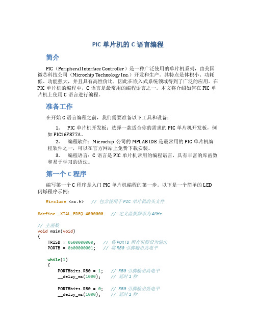
第一个C程序编写第一个C程序是入门PIC单片机编程的第一步。
以下是一个简单的LED闪烁程序示例:#include <xc.h>// 包含使用于PIC单片机的头文件#define _XTAL_FREQ 4000000 // 定义晶振频率为4MHz// 主函数void main(void){TRISB = 0b00000000; // 将PORTB所有引脚设为输出PORTB = 0b00000001; // 将RB0引脚输出高电平while(1){PORTBbits.RB0 = 1; // RB0引脚输出高电平__delay_ms(1000); // 延时1秒PORTBbits.RB0 = 0; // RB0引脚输出低电平__delay_ms(1000); // 延时1秒}}在这个程序中,我们使用了xc.h头文件来包含适用于PIC单片机的库函数和宏定义。
使用#define指令定义了晶振频率为4MHz,可以根据自己的实际情况进行修改。
在main函数中,通过TRISB寄存器将PORTB所有引脚设置为输出模式,并使用PORTB寄存器将RB0引脚输出高电平。
PIC快速入门版

在PIC单片机系列中,改变I/O口的输入输出依靠写入寄存器TRIS的值,相应位写0,表示对应管脚被定义成了输出,写1,就是输入。
现在假如预把GP1、GP2管脚定义成输出,其他脚全是输入。
那就应该向TRIS 寄存器写入二进制数11111001,换算成十六进制就是F9H.依照以前我们学到的知识,在PIC系列单片机里,本来应该用下列的语句来完成我们的设定:movlw 0F9H '常数进W 以字母开头的常数前面必须加0movwf TRISA'把W内的数复制到TRIS实际上PIC系列的单片机也都是这么写的,后面加的A,表示第一个8位的口(有的单片机不仅一个口,还有好几个8位的I/O口如TRISB TRISC TRISD等等) .但是,记住了, PIC12系列的单片机必须改写成为:movlw 0F9H '常数进W 以字母开头的常数前面必须加0tris GPIO '把W内的数复制到TRIS 以后凡见到这个指令一律理解成movwf TRISA写法不同,意思是一样的. 这样你就又学了一个指令TRIS,不过这个指令的实质还是你曾经学过的movwf 只是写法不同罢了.在PIC12系列里TRIS作为指令, 在其他系列(PIC16\17\18)里把TRIS 作为普通寄存器看待.因为我们现在讲的就是PIC12CE519,所以我们暂时用tris GPIO这个格式,等以后进入PIC16C877 我们再写成movwf TRISA , 至于理解按照后者进行.'-----------如果我们要控制GP1 GP2管脚的输出电平, 其他管脚作为输入.并且让GP1输出低电平,GP2输出高电平.完整的程序如下:movlw 0F9H '常数进Wtris GPIO '把W内的数复制到TRIS ,GP1 GP2为输出,其他为输入'此行无命令,起到的作用是容易读懂程序movlw 04H '常数4的二进制是00000100 ,GP1=0 GP2=1movwf GPIO 'W内的数进GPIO 输出生效,原来定义成输入的脚的电平,不会受该句影响?上面已经学会了三条指令,但是8位寄存器的概念概念一定要建立起来,程序通过写入寄存器不同的数据控制管脚作为输入使用还是输出使用,作为输出时是输出高电平还是低电平。
Microchip dsPIC30F 系列参考手册说明书

6Section 6. InterruptsHIGHLIGHTSThis section of the manual contains the following topics:6.1Introduction....................................................................................................................6-26.2Non-Maskable Traps......................................................................................................6-66.3Interrupt Processing Timing.........................................................................................6-116.4Interrupt Control and Status Registers.........................................................................6-146.5Interrupt Setup Procedures..........................................................................................6-426.6Register Map................................................................................................................6-436.7Design Tips..................................................................................................................6-446.8Related Application Notes............................................................................................6-456.9Revision History...........................................................................................................6-46dsPIC30F Family Reference Manual6.1IntroductionThe dsPIC30F interrupt controller module reduces the numerous peripheral interrupt requestsignals to a single interrupt request signal to the dsPIC30F CPU and has the following features:•Up to 8 processor exceptions and software traps•7 user selectable priority levels•Interrupt Vector Table (IVT) with up to 62 vectors• A unique vector for each interrupt or exception source•Fixed priority within a specified user priority level•Alternate Interrupt Vector Table (AIVT) for debug support•Fixed interrupt entry and return latencies6.1.1Interrupt Vector TableThe Interrupt Vector Table (IVT) is shown in Figure6-1. The IVT resides in program memory,starting at location 0x000004. The IVT contains 62 vectors consisting of 8 non-maskable trapvectors plus up to 54 sources of interrupt. In general, each interrupt source has its own vector.Each interrupt vector contains a 24-bit wide address. The value programmed into each interruptvector location is the starting address of the associated Interrupt Service Routine (ISR).6.1.2Alternate Vector TableThe Alternate Interrupt Vector Table (AIVT) is located after the IVT as shown in Figure6-1.Access to the AIVT is provided by the ALTIVT control bit (INTCON2<15>). If the ALTIVT bit isset, all interrupt and exception processes will use the alternate vectors instead of the defaultvectors. The alternate vectors are organized in the same manner as the default vectors.The AIVT supports emulation and debugging efforts by providing a means to switch betweenan application and a support environment without requiring the interrupt vectors to bereprogrammed. This feature also enables switching between applications for evaluation ofdifferent software algorithms at run-time. If the AIVT is not needed, the AIVT should beprogrammed with the same addresses used in the IVT.6.1.3Reset SequenceA device Reset is not a true exception because the interrupt controller is not involved in the Resetprocess. The dsPIC30F device clears its registers in response to a Reset which forces the PC tozero. The processor then begins program execution at location 0x000000. The user programsa GOTO instruction at the Reset address which redirects program execution to the appropriatestart-up routine.Note:Any unimplemented or unused vector locations in the IVT and AIVT should beprogrammed with the address of a default interrupt handler routine that contains aRESET instruction.Section 6. Interrupts 6Figure 6-1:Interrupt Vector TableTable 6-1:Trap Vector Details D e c r e a s i n g N a t u r a l O r d e r P r i o r i t y 0x0000000x000014Reserved Address Error Trap Vector Stack Error Trap Vector Reserved Reserved Reserved Interrupt Vector 0Interrupt Vector 1———Interrupt Vector 52Interrupt Vector 53Arithmetic Error Trap Vector Oscillator Fail Trap Vector ReservedInterrupt Vector 0Interrupt Vector 1———Interrupt Vector 52Interrupt Vector 53IVTAIVT 0x0000800x00007E 0x0000FEReserved Reserved Address Error Trap Vector Stack Error Trap Vector ReservedReservedArithmetic Error Trap Vector Oscillator Fail Trap Vector 0x000094Reset – GOTO Instruction Reset – GOTO Address 0x000002Reserved 0x0000820x0000840x000004See Table 6-2Vector details.for Interrupt VectorNumberIVT Address AIVT Address Trap Source0x0000040x000084Reserved 10x0000060x000086Oscillator Failure 20x0000080x000088Address Error 30x00000A 0x00008A Stack Error 40x00000C 0x00008C Arithmetic Error 50x00000E 0x00008E Reserved 60x0000100x000090Reserved 70x0000120x000092ReserveddsPIC30F Family Reference ManualTable 6-2:Interrupt Vector DetailsVectorIVT Address AIVT Address Interrupt SourceNumber80x0000140x000094INT0 – External Interrupt 090x0000160x000096IC1 – Input Compare 1100x0000180x000098OC1 – Output Compare 1110x00001A0x00009A T1 – Timer 1120x00001C0x00009C IC2 – Input Capture 2130x00001E0x00009E OC2 – Output Compare 2140x0000200x0000A0T2 – Timer 2150x0000220x0000A2T3 – Timer 3160x0000240x0000A4SPI1170x0000260x0000A6U1RX – UART1 Receiver180x0000280x0000A8U1TX – UART1 Transmitter190x00002A0x0000AA ADC – ADC Convert Done200x00002C0x0000AC NVM – NVM Write Complete210x00002E0x0000AE I2C™ Slave Operation – MessageDetect220x0000300x0000B0I2C Master Operation – MessageEvent Complete230x0000320x0000B2Change Notice Interrupt240x0000340x0000B4INT1 – External Interrupt 1250x0000360x0000B6IC7 – Input Capture 7260x0000380x0000B8IC8 – Input Capture 8270x00003A0x0000BA OC3 – Output Compare 3280x00003C0x0000BC OC4 – Output Compare 4290x00003E0x0000BE T4 – Timer 4300x0000400x0000C0T5 – Timer 5310x0000420x0000C2INT2 – External Interrupt 2320x0000440x0000C4U2RX – UART2 Receiver330x0000460x0000C6U2TX – UART2 Transmitter340x0000480x0000C8SPI2350x00004A0x0000CA CAN1360x00004C0x0000CC IC3 – Input Capture 3370x00004E0x0000CE IC4 – Input Capture 4380x0000500x0000D0IC5 – Input Capture 5390x0000520x0000D2IC6 – Input Capture 6400x0000540x0000D4OC5 – Output Compare 5410x0000560x0000D6OC6 – Output Compare 6420x0000580x0000D8OC7 – Output Compare 7430x00005A0x0000DA OC8 – Output Compare 8440x00005C0x0000DC INT3 – External Interrupt 3450x00005E0x0000DE INT4 – External Interrupt 4460x0000600x0000E0CAN2470x0000620x0000E2PWM – PWM Period Match480x0000640x0000E4QEI – Position Counter Compare490x0000660x0000E6DCI – Codec Transfer Done500x0000680x0000E8LVD – Low Voltage Detect510x00006A0x0000EA FLTA – MCPWM Fault A520x00006C0x0000EC FLTB – MCPWM Fault B53-610x00006E-0x00007E0x00006E-0x00007E ReservedSection 6. Interrupts6 6.1.4CPU Priority StatusThe CPU can operate at one the of sixteen priority levels, 0-15. An interrupt or trap source musthave a priority level greater than the current CPU priority in order to initiate an exception process.Peripheral and external interrupt sources can be programmed for level 0-7, while CPU prioritylevels 8-15 are reserved for trap sources. A trap is a non-maskable interrupt source intended todetect hardware and software problems (see Section 6.2 “Non-Maskable Traps”). The prioritylevel for each trap source is fixed and only one trap is assigned to a priority level. Note that aninterrupt source programmed to priority level 0 is effectively disabled, since it can never begreater than the CPU priority.The current CPU priority level is indicated by the following four status bits:•IPL<2:0> status bits located in SR<7:5>•IPL3 status bit located in CORCON<3>The IPL<2:0> status bits are readable and writable, so the user may modify these bits to disableall sources of interrupts below a given priority level. If IPL<2:0> = 3, for example, the CPU willnot be interrupted by any source with a programmed priority level of 0, 1, 2 or 3.Trap events have higher priority than any user interrupt source. When the IPL3 bit is set, a trapevent is in progress. The IPL3 bit can be cleared, but not set by the user. In some applications,it may be desirable to clear the IPL3 bit when a trap has occurred and branch to an instructionother than the instruction after the one that originally caused the trap to occur.All user interrupt sources can be disabled by setting IPL<2:0> = 111.Note:The IPL<2:0> bits become read only bits when interrupt nesting is disabled. SeeSection 6.2.4.2 “Interrupt Nesting” for more information.6.1.5Interrupt PriorityEach peripheral interrupt source can be assigned to one of the seven priority levels. The userassignable interrupt priority control bits for each individual interrupt are located in the LeastSignificant 3 bits of each nibble within the IPCx register(s). Bit 3 of each nibble is not used andis read as a ‘0’. These bits define the priority level assigned to a particular interrupt. The usablepriority levels start at ‘1’ as the lowest priority and level 7 as the highest priority. If the IPC bitsassociated with an interrupt source are all cleared, then the interrupt source is effectivelydisabled.Note:If the application program reconfigures the interrupt priority levels on the fly, it mustdisable the interrupts while doing so. Failure to disable interrupts can produceunexpected results.Since more than one interrupt request source may be assigned to a specific priority level, anoption is provided to resolve priority conflicts within a given user-assigned level. Each source ofinterrupt has a natural order priority based on its location in the IVT. Table6-2 shows the locationof each interrupt source in the IVT. The lower numbered interrupt vectors have higher naturalpriority, while the higher numbered vectors have lower natural priority. The overall priority levelfor any pending source of interrupt is determined first by the user-assigned priority of that sourcein the IPCx register, then by the natural order priority within the IVT.Natural order priority is used only to resolve conflicts between simultaneous pending interruptswith the same user-assigned priority level. Once the priority conflict is resolved and the exceptionprocess begins, the CPU can only be interrupted by a source with a higher user-assigned priority.Interrupts with the same user-assigned priority but a higher natural order priority, that becomepending after the exception process begins, will remain pending until the current exceptionprocess completes.The ability for the user to assign each interrupt source to one of seven priority levels means thatthe user can give an interrupt with a low natural order priority a very high overall priority level. Forexample: the PLVD (Programmable Low Voltage Detect) can be given a priority of 7 and the INT0(External Interrupt 0) may be assigned to priority level 1, thus giving it a very low effective priority.Note:The peripherals and sources of interrupt available in the IVT will vary depending onthe specific dsPIC30F device. The sources of interrupt shown in this documentrepresent a comprehensive listing of all interrupt sources found on dsPIC30Fdevices. Refer to the specific device data sheet for further details.dsPIC30F Family Reference Manual6.2Non-Maskable TrapsTraps can be considered as non-maskable, nestable interrupts which adhere to a fixed prioritystructure. Traps are intended to provide the user a means to correct erroneous operation duringdebug and when operating within the application. If the user does not intend to take correctiveaction in the event of a trap error condition, these vectors must be loaded with the address of asoftware routine that will reset the device. Otherwise, the trap vector is programmed with theaddress of a service routine that will correct the trap condition.The dsPIC30F has the four implemented sources of non-maskable traps listed below:•Oscillator Failure Trap•Stack Error Trap•Address Error Trap•Arithmetic Error TrapNote that many of these trap conditions can only be detected when they happen. Consequently,the instruction that caused the trap is allowed to complete before exception processing begins.Therefore, the user may have to correct the action of the instruction that caused the trap.Each trap source has a fixed priority as defined by its position in the IVT. An oscillator failure traphas the highest priority, while an arithmetic error trap has the lowest priority (see Figure6-1). Inaddition, trap sources are classified into two distinct categories: ‘Hard’ traps and ‘Soft’ traps. 6.2.1Soft TrapsThe arithmetic error trap (priority level 11) and stack error trap (priority level 12) are categorizedas ‘soft’ trap sources. Soft traps can be treated like non-maskable sources of interrupt thatadhere to the priority assigned by their position in the IVT. Soft traps are processed like interruptsand require 2 cycles to be sampled and Acknowledged prior to exception processing. Therefore,additional instructions may be executed before a soft trap is Acknowledged.6.2.1.1Stack Error Trap (Soft Trap, Level 12)The stack is initialized to 0x0800 during Reset. A stack error trap will be generated should thestack pointer address ever be less than 0x0800.There is a Stack Limit register (SPLIM) associated with the stack pointer that is uninitialized atReset. The stack overflow check is not enabled until a word write to SPLIM occurs.All Effective Addresses (EA) generated using W15 as a source or destination pointer arecompared against the value in SPLIM. Should the EA be greater than the contents of the SPLIMregister, then a stack error trap is generated. In addition, a stack error trap will be generatedshould the EA calculation wrap over the end of data space (0xFFFF).A stack error can be detected in software by polling the STKERR status bit (INTCON1<2>). Toavoid re-entering the Trap Service Routine, the STKERR status flag must be cleared in softwareprior to returning from the trap with a RETFIE instruction.Section 6. Interrupts6 6.2.1.2Arithmetic Error Trap (Soft Trap, Level 11)Any of the following events will cause an arithmetic error trap to be generated:•Accumulator A Overflow•Accumulator B Overflow•Catastrophic Accumulator Overflow•Divide by Zero•Shift Accumulator (SFTAC) operation exceeding +/-16 bitsThere are three enable bits in the INTCON1 register that enable the three types of accumulatoroverflow traps. The OVATE control bit (INTCON1<10>) is used to enable traps for anAccumulator A overflow event. The OVBTE control bit (INTCON1<9>) is used to enable traps foran Accumulator B overflow event. The COVTE control bit (INTCON1<8>) is used to enable trapsfor a catastrophic overflow of either accumulator.An Accumulator A or Accumulator B overflow event is defined as a carry-out from bit 31. Notethat no accumulator overflow can occur if the 31-bit Saturation mode is enabled for theaccumulator. A catastrophic accumulator overflow is defined as a carry-out from bit 39 of eitheraccumulator. No catastrophic overflow can occur if accumulator saturation (31-bit or 39-bit) isenabled.Divide-by-zero traps cannot be disabled. The divide-by-zero check is performed during the firstiteration of the REPEAT loop that executes the divide instruction.Accumulator shift traps cannot be disabled. The SFTAC instruction can be used to shift theaccumulator by a literal value or a value in one of the W registers. If the shift value exceeds+/-16bits, an arithmetic trap will be generated. The SFTAC instruction will execute, but the resultsof the shift will not be written to the target accumulator.An arithmetic error trap can be detected in software by polling the MATHERR status bit(INTCON1<4>). To avoid re-entering the Trap Service Routine, the MATHERR status flag mustbe cleared in software prior to returning from the trap with a RETFIE instruction. Before theMATHERR status bit can be cleared, all conditions that caused the trap to occur must also becleared. If the trap was due to an accumulator overflow, the OA and OB status bits (SR<15:14>)must be cleared. The OA and OB status bits are read only, so the user software must perform adummy operation on the overflowed accumulator (such as adding ‘0’) that will cause thehardware to clear the OA or OB status bit.6.2.2Hard TrapsHard traps include exceptions of priority level 13 through level 15, inclusive. The address error(level13) and oscillator error (level 14) traps fall into this category.Like soft traps, hard traps can also be viewed as non-maskable sources of interrupt. Thedifference between hard traps and soft traps is that hard traps force the CPU to stop codeexecution after the instruction causing the trap has completed. Normal program execution flowwill not resume until after the trap has been Acknowledged and processed.6.2.2.1Trap Priority and Hard Trap ConflictsIf a higher priority trap occurs while any lower priority trap is in progress, processing of the lowerpriority trap will be suspended and the higher priority trap will be Acknowledged and processed.The lower priority trap will remain pending until processing of the higher priority trap completes.Each hard trap that occurs must be Acknowledged before code execution of any type maycontinue. If a lower priority hard trap occurs while a higher priority trap is pending, Acknowledged,or is being processed, a hard trap conflict will occur. The conflict occurs because the lowerpriority trap cannot be Acknowledged until processing for the higher priority trap completes.The device is automatically reset in a hard trap conflict condition. The TRAPR status bit(RCON<15>) is set when the Reset occurs, so that the condition may be detected in software.dsPIC30F Family Reference Manual6.2.2.2Oscillator Failure Trap (Hard Trap, Level 14)An oscillator failure trap event will be generated for any of the following reasons:•The Fail-Safe Clock Monitor (FSCM) is enabled and has detected a loss of the systemclock source.• A loss of PLL lock has been detected during normal operation using the PLL.•The FSCM is enabled and the PLL fails to achieve lock at a Power-On Reset (POR).An oscillator failure trap event can be detected in software by polling the OSCFAIL status bit(INTCON1<1>), or the CF status bit (OSCCON<3>). To avoid re-entering the Trap ServiceRoutine, the OSCFAIL status flag must be cleared in software prior to returning from the trap witha RETFIE instruction.For more information about the FSCM, refer to Section 7.“Oscillator” and Section24.“Device Configuration”.6.2.2.3Address Error Trap (Hard Trap, Level 13)The following paragraphs describe operating scenarios that would cause an address error trapto be generated:1. A misaligned data word fetch is attempted. This condition occurs when an instructionperforms a word access with the LSb of the effective address set to ‘1’. The dsPIC30FCPU requires all word accesses to be aligned to an even address boundary.2. A bit manipulation instruction using the Indirect Addressing mode with the LSb of theeffective address set to ‘1’.3. A data fetch from unimplemented data address space is attempted.4.Execution of a “BRA #litera l” instruction or a “GOTO #literal” instruction, whereliteral is an unimplemented program memory address.5.Executing instructions after modifying the PC to point to unimplemented program memoryaddresses. The PC may be modified by loading a value into the stack and executing aRETURN instruction.Data space writes will be inhibited whenever an address error trap occurs, so that data is notdestroyed.An address error can be detected in software by polling the ADDRERR status bit (INTCON1<3>).To avoid re-entering the Trap Service Routine, the ADDRERR status flag must be cleared insoftware prior to returning from the trap with a RETFIE instruction.Note:In the MAC class of instructions, the data space is split into X and Y spaces. In theseinstructions, unimplemented X space includes all of Y space, and unimplemented Yspace includes all of X space.6.2.3Disable Interrupts InstructionThe DISI (disable interrupts) instruction has the ability to disable interrupts for up to 16384instruction cycles. This instruction is useful when time critical code segments must be executed.The DISI instruction only disables interrupts with priority levels 1-6. Priority level 7 interrupts andall trap events still have the ability to interrupt the CPU when the DISI instruction is active.The DISI instruction works in conjunction with the DISICNT register. When the DISICNT registeris non-zero, priority level 1-6 interrupts are disabled. The DISICNT register is decremented oneach subsequent instruction cycle. When the DISICNT register counts down to ‘0’, prioritylevel1-6 interrupts will be re-enabled. The value specified in the DISI instruction includes allcycles due to PSV accesses, instruction stalls, etc.The DISICNT register is readable and writable. The user can terminate the effect of a previousDISI instruction early by clearing the DISICNT register. The amount of time that interrupts aredisabled can also be increased by writing to or adding to DISICNT.Section 6. Interrupts 6Note that if the DISICNT register is zero, interrupts cannot be disabled by writing a non-zero value to the register. Interrupts must first be disabled by using the DISI instruction. Once the DISI instruction has executed and DISICNT holds a non-zero value, the interrupt disable time can be extended by modifying the contents of DISICNT.The DISI status bit (INTCON2<14>) is set whenever interrupts are disabled as a result of the DISI instruction.6.2.4Interrupt OperationAll interrupt event flags are sampled during each instruction cycle. A pending Interrupt Request (IRQ) is indicated by the flag bit being equal to a ‘1’ in an IFSx register. The IRQ will cause an interrupt to occur if the corresponding bit in the Interrupt Enable (IECx) registers is set. For the rest of the instruction cycle in which the IRQ is sampled, the priorities of all pending interrupt requests are evaluated.No instruction will be aborted when the CPU responds to the IRQ. The instruction that was in progress when the IRQ is sampled will be completed before the ISR is executed.If there is a pending IRQ with a user-assigned priority level greater than the current processor priority level, indicated by the IPL<2:0> status bits (SR<7:5>), an interrupt will be presented to the processor. The processor then saves the following information on the software stack:•the current PC value•the low byte of the Processor Status register (SRL)•the IPL3 status bit (CORCON<3>)These three values that are saved on the stack allow the return PC address value, MCU status bits, and the current processor priority level to be automatically saved.After the above information is saved on the stack, the CPU writes the priority level of the pending interrupt into the IPL<2:0> bit locations. This action will disable all interrupts of less than, or equal priority, until the Interrupt Service Routine (ISR) is terminated using the RETFIE instruction. Figure 6-2:Stack Operation for Interrupt Event 6.2.4.1Return from InterruptThe RETFIE (Return from Interrupt) instruction will unstack the PC return address, IPL3 status bit and SRL register to return the processor to the state and priority level prior to the interrupt sequence.Note:Software modification of the DISICNT register is not recommended.Note:The DISI instruction can be used to quickly disable all user interrupt sources if nosource is assigned to CPU priority level 7.<Free Word>PC<15:0>PC<22:16>015W15 (before IRQ)W15 (after IRQ)S t a c k G r o w s T o w a r d s H i g h e r A d d r e s s SR<7:0>This stack location used to store the IPL3 status bit (CORCON<3>).dsPIC30F Family Reference Manual6.2.4.2Interrupt NestingInterrupts, by default, are nestable. Any ISR that is in progress may be interrupted by anothersource of interrupt with a higher user-assigned priority level. Interrupt nesting may be optionallydisabled by setting the NSTDIS control bit (INTCON1<15>). When the NSTDIS control bit is set,all interrupts in progress will force the CPU priority to level 7 by setting IPL<2:0> = 111. Thisaction will effectively mask all other sources of interrupt until a RETFIE instruction is executed.When interrupt nesting is disabled, the user-assigned interrupt priority levels will have no effect,except to resolve conflicts between simultaneous pending interrupts.The IPL<2:0> bits become read only when interrupt nesting is disabled. This prevents the usersoftware from setting IPL<2:0> to a lower value, which would effectively re-enable interruptnesting.6.2.5Wake-up from Sleep and IdleAny source of interrupt that is individually enabled, using its corresponding control bit in the IECxregisters, can wake-up the processor from Sleep or Idle mode. When the interrupt status flag fora source is set and the interrupt source is enabled via the corresponding bit in the IEC Controlregisters, a wake-up signal is sent to the dsPIC30F CPU. When the device wakes from Sleep orIdle mode, one of the following actions may occur:1.If the interrupt priority level for that source is greater than the current CPU priority level,then the processor will process the interrupt and branch to the ISR for the interrupt source.2.If the user-assigned interrupt priority level for the source is less than or equal the currentCPU priority level, then the processor will simply continue execution, starting with theinstruction immediately following the PWRSAV instruction that previously put the CPU inSleep or Idle mode.Note:User interrupt sources that are assigned to CPU priority level 0 cannot wake theCPU from Sleep or Idle mode, because the interrupt source is effectively disabled.To use an interrupt as a wake-up source, the CPU priority level for the interrupt mustbe assigned to CPU priority level 1 or greater.6.2.6A/D Converter External Conversion RequestThe INT0 external interrupt request pin is shared with the A/D converter as an externalconversion request signal. The INT0 interrupt source has programmable edge polarity, which isalso available to the A/D converter external conversion request feature.6.2.7External Interrupt SupportThe dsPIC30F supports up to 5 external interrupt pin sources (INT0-INT4). Each externalinterrupt pin has edge detection circuitry to detect the interrupt event. The INTCON2 register hasfive control bits (INT0EP-INT4EP) that select the polarity of the edge detection circuitry. Eachexternal interrupt pin may be programmed to interrupt the CPU on a rising edge or falling edgeevent. See Register6-4 for further details.。
PIC单片机基础教程

PIC单片机基础教程一、介绍单片机是一种集成了微处理器核心、存储器、外设接口等功能于一芯片上的微型计算机系统,广泛应用于各种电子设备中。
其中,PIC单片机是由微芯科技公司所生产的单片机系列产品,具有低成本、高性能、易编程等特点,被广泛应用于各个领域。
二、单片机基础知识1.硬件组成:PIC单片机包含微处理器核心、存储器、电源和时钟、IO口、ADC/DAC、串口等硬件组件,这些组件共同协作完成各种任务。
2. 存储器类型:PIC单片机主要有Flash存储器和RAM存储器,Flash存储器用于存储程序代码和常量数据,RAM存储器用于存储变量数据。
3.计时器/计数器:PIC单片机内置了多个计时器/计数器,用于进行时间测量、频率计算等操作。
4.IO口:PIC单片机具有多个IO口,可以通过IO口与外部器件进行数据交互。
5.ADC/DAC:PIC单片机内置了ADC(模数转换器)和DAC(数模转换器),可以实现模拟信号的采集和输出。
6.串口通信:PIC单片机支持串口通信,可以与其他设备进行数据通信。
7.中断:PIC单片机具有中断功能,可以在一些事件发生时暂停当前任务,执行中断服务程序。
三、PIC单片机开发工具1.MPLABIDE:这是一款由微芯科技公司提供的PIC单片机开发集成开发环境,可以用于编写、编译、调试PIC单片机的代码。
2. Hi-Tech C编译器:这是一款专门用于PIC单片机的C语言编译器,可以将C语言代码编译成PIC单片机可以执行的机器码。
3. PICKit:这是一款由微芯科技公司提供的PIC单片机编程器和调试器,可以与PIC单片机进行连接,用于烧录程序和进行调试。
四、PIC单片机编程基础1.引脚定义:在编程之前,首先需要定义PIC单片机的IO引脚,以便与外部器件进行连接。
2.程序结构:PIC单片机的程序结构由初始化、主循环和中断服务程序等部分组成。
3.输入输出操作:通过IO口可以实现数码管显示、LED亮灭、开关输入等操作。
PIC汇编语言指令

PIC 8位单片机共有三个级别,有相对应的指令集。
基本级PIC系列芯片共有指令33条,每条指令是12位字长;中级PIC系列芯片共有指令35条,每条指令是14位字长;高级PIC系列芯片共有指令58条,每条指令是16位字长。
其指令向下兼容。
一、PIC汇编语言指令格式PIC系列微控制器汇编语言指令与MCS-51系列单片机汇编语言一样,每条汇编语言指令由4个部分组成,其书写格式如下:标号操作码助记符操作数1,操作数2;注释指令格式说明如下:指令的4个部分之间由空格作隔离符,空格可以是1格或多格,以保证交叉汇编时,PC机能识别指令。
1标号与MCS-51系列单片机功能相同,标号代表指令的符号地址。
在程序汇编时,已赋以指令存储器地址的具体数值。
汇编语言中采用符号地址(即标号)是便于查看、修改,尤其是便于指令转移地址的表示。
标号是指令格式中的可选项,只有在被其它语句引用时才需派上标号。
在无标号的情况下,指令助记符前面必须保留一个或一个以上的空格再写指令助记符。
指令助记符不能占用标号的位置,否则该助记符会被汇编程序作标号误处理。
书写标号时,规定第一字符必须是字母或半角下划线“—”,它后面可以跟英文和数字字符、冒号(:)制符表等,并可任意组合。
再有标号不能用操作码助记符和寄存器的代号表示。
标号也可以单独占一行。
2操作码助记符该字段是指令的必选项。
该项可以是指令助记符,也可以由伪指令及宏命令组成,其作用是在交叉汇编时,“指令操作码助记符”与“操作码表”进行逐一比较,找出其相应的机器码一一代之。
3操作数由操作数的数据值或以符号表示的数据或地址值组成。
若操作数有两个,则两个操作数之间用逗号(,)分开。
当操作数是常数时,常数可以是二进制、八进制、十进制或十六进制数。
还可以是被定义过的标号、字符串和ASCⅡ码等。
具体表示时,规定在二进制数前冠以字母“B”,例如B;八进制数前冠以字母“O”,例如O257;十进制数前冠以字母“D”,例如D122;十六进制数前冠以“H”,例如H2F。
对dsPIC系列单片机C语言编程中乘除法计算的编程感悟

对dsPIC系列单⽚机C语⾔编程中乘除法计算的编程感悟个⼈使⽤单⽚机有些时间了,尤其是在这个快速变化的时代,数字编程已经是⼯科⽣必备的素养了。
虽然说单⽚机现在也⽀持C语⾔编程了,但是和计算机的C语⾔编程也存在⼀些差异,尤其是在进⾏数据乘除法计算的时候。
有些单⽚机不⼀定使⽤的标准C语⾔编译器,请注意不同单⽚机的编程风格,具体请单⽚机从以前的汇编,逐渐⽀持C语⾔编译器,但是可能⽀持部分C语⾔,不⼀定是标准的C语⾔编译器。
以dsPIC单⽚机为例,以下有两种C语⾔除法编程风格:uint16_t a;uint16_t temp;uint16_t b;//example 1:标准C语⾔编译器的除法b = (a << 10)/1023;//example 2: dsPIC 单⽚机⽀持的乘法与除法temp = __builtin_muluu(a,1024);b = __builtini_divud(temp,1023);上⾯两种写法,第⼀种计算结果是正确的,只有第⼆种写法在dsPIC单⽚机上才能得到正常的结果。
根本的原因在于编译器对整形乘除数据,处理⽅式不⼀样。
以下有两种C语⾔乘法编程风格:uint16_t a;uint16_t b;long c;long d;a = 32676;b = 32676;//example 1: 标准C语⾔的⽆符号整数乘法c = a * b;//example 2: dsPIC内部⾃带的⽆符号整数乘法d = __builtin_muluu(a,b);uint16_t a;uint16_t b;long c;long d;a = 256;b = 256;//example 3: 标准C语⾔的⽆符号整数乘法c = a * b;//example 4: dsPIC内部⾃带的⽆符号整数乘法d = __builtin_muluu(a,b);上⾯两种写法,第⼀种计算的结果是错误的,第⼆种计算的结果是正确的。
说明
1、PIC 集成开发环境(PIC 的开发软件,集成 PIC 程序编写、编译、调试的环 境) 解压安装:光盘\软件\MPLAB_IDE 集成开发环境 ICD2、KIT2、KIT3 都可以在这个软件上进行烧写、调试程序 2、PIC C 语言开发软件 PIC C 语言软件是需要另外安装的,在挂在 MPLAB_IDE 集成开发环境中使 用的 PIC10F 、 PIC12F 系 列: 光盘 \ 软 件 \HI-TECH C Compiler for PIC101216 MCUs-v9.70 PIC16F 系列:光盘\软件\picc_c 语言开发工具 PIC18F 系列:光盘\软件\ mplab-c18-v3_02.rar PIC33F、30F 系列:光盘\软件\正版 MAPLAB C30 PIC24F 系列:安装好 C30 后,安装:光盘\软件\ C30 update for pic24 dspic to V3.20_cn544578.rar 3、独立烧写软件 ICD2:无 KIT2:光盘\软件\ PICkit 2 v2.61.00 Setup.zip KIT3:光盘\软件\ PICkit_3_独立烧写软件 1_0_Setup_A.zip
淘宝 ID:wang2684:汪工
安装阿里旺旺软件直接联系
二、工具使用:具体操作请查看光盘相应文件内详细说明 三、工具支持:工具随着 MPLAB
IDE 软件的升级,支持的 IC 也会有更新,
开发工具也会随软件自动升级。 打开 MPLAB IDE 软件, configure->select device 以 PIC16F877A 为例,1 的位置相应工具前面绿色,表示支持在线烧写的。 2 的位置相应工具前面绿色,表示支持在线调试的,但是要注意 3 的位置, 如果是红色就不需要仿真头,如果是绿色的话,会有相应的仿真头型号显示,就
PIC单片机C语言编程入门

PICC入门笔记PIC单片机C语言编程入门笔记一、C语言基础复习--------没C语言基础看起来可能有点困难。
(1) 条件判断语句if语句,switch语句(2) 循环执行语句do while语句,while语句,for语句(3) 转向语句break语句,goto语句,continue语句,return语句第三章: 控制语句1.if语句C语言的if语句有三种基本形式。
1、如果表达式的值为真,则执行其后的语句,否则不执行该语句。
if(表达式) 语句;2、如果表达式的值为真,则执行语句1,否则执行语句2 。
If(表达式)语句1;else语句2;3、依次判断表达式的值,当出现某个值为真时,则执行其对应的语句。
然后跳到整个if语句之外继续执行程序。
如果所有的表达式均为假,则执行语句n 。
然后继续执行后续程序。
If(表达式1)语句1;else if(表达式2)语句2;else if(表达式3)语句3;…else if(表达式m)语句m;else语句n;2、条件运算符和条件表达式由条件运算符组成条件表达式的一般形式为:表达式1? 表达式2:表达式3其求值规则为:如果表达式1的值为真,则以表达式2 的值作为条件表达式的值,否则以表达式3的值作为整个条件表达式的值。
例:max=(a>b)?a:b;意义:如果在条件语句中,只执行单个的赋值语句时,常可使用条件表达式来实现。
不但使程序简洁,也提高了运行效率。
3、switch语句C语言还提供了另一种用于多分支选择的switch语句,其一般形式为:switch(表达式){case常量表达式1: 语句1;case常量表达式2: 语句2;…case常量表达式n: 语句n;default : 语句n+1;}其语义是:计算表达式的值。
并逐个与其后的常量表达式值相比较,当表达式的值与某个常量表达式的值相等时,即执行其后的语句,然后不再进行判断,继续执行后面所有case后的语句。
pic单片机c语言

PIC单片机 C 语言一、简介PIC(Peripheral Interface Controller)单片机是一种微控制器系列,由美国微芯科技公司推出。
PIC单片机广泛应用于嵌入式系统、自动化控制、仪器仪表等领域。
本文将介绍PIC单片机C语言编程的基础知识。
二、PIC单片机的开发环境准备在开始PIC单片机C语言编程前,我们需要准备开发环境。
以下是常用的开发环境工具:•MPLAB X IDE:Microchip官方推出的集成开发环境(IDE)。
可从Microchip官网免费下载。
•XC8编译器:Microchip官方提供的C语言编译器。
与MPLAB X IDE 配合使用,可编译生成PIC单片机的机器语言。
•PICKIT系列编程器:用于将编译生成的机器语言烧录到PIC单片机中。
在安装好开发环境工具后,我们可以开始进行PIC单片机C语言编程了。
三、PIC单片机的基本语法PIC单片机C语言编程的语法与标准C语言相似,但也有一些特殊的语法规则需要注意。
以下是一些常用的语法要点:1. 声明和定义变量在PIC单片机C语言中,我们可以使用关键字int、char、float等来声明和定义变量。
例如:int a; // 声明一个整型变量achar b; // 声明一个字符型变量bfloat c; // 声明一个浮点型变量c2. 控制语句PIC单片机C语言中的控制语句与标准C语言相似,包括条件语句、循环语句等。
例如:if (condition) {// 条件为真时执行的代码} else {// 条件为假时执行的代码}while (condition) {// 循环体}for (initialization; condition; update) {// 循环体}3. 函数在PIC单片机C语言中,我们可以定义和调用函数。
例如:int add(int a, int b) {return a + b;}int result = add(3, 5); // 调用函数add,并将返回值赋给result变量四、PIC单片机C语言编程实例下面我们以一个简单的实例来演示PIC单片机C语言编程的过程。
pic单片机教程

pic单片机教程什么是pic单片机?PIC(Peripherally Integrated Circuit)单片机是一种微控制器,最初由美国的Microchip Technology Inc.公司开发。
它们是一种将CPU、内存和其他电子元件集成到一个芯片上的集成电路。
PIC单片机是非常受欢迎的,因为它们具有易于使用、低功耗和高性能的特点。
PIC单片机在很多应用中都有广泛的应用,比如电子产品、家电、汽车等等。
由于其灵活性和实用性,学习PIC单片机编程也成为许多电子爱好者和专业开发者的首选。
如何开始使用PIC单片机?准备硬件设备和开发工具要开始学习PIC单片机编程,首先你需要准备一些硬件设备和开发工具。
1.PIC单片机芯片:根据自己的需要选择合适的芯片型号。
常见的有PIC16系列、PIC18系列和PIC32系列。
你可以根据项目的需求选择不同型号的芯片。
2.开发板:开发板是用来容纳芯片的平台,它通常已经将一些基本的外设集成到了板上,比如按键、LED、LCD等。
你可以购买现成的开发板,也可以自己设计并制作一个。
3.烧录器:烧录器用于将编写好的程序下载到芯片中。
常见的烧录器有PICkit、ICD等。
根据你选择的芯片型号,选择对应的烧录器。
4.开发工具:Microchip公司提供了一套完整的开发工具,包括集成开发环境(IDE)和编译器。
你可以下载并安装它们来进行PIC单片机编程。
除此之外,也有一些第三方的开发工具可供选择。
学习PIC单片机编程基础知识学习PIC单片机编程之前,你需要先掌握一些基础知识。
1.C语言:PIC单片机可以使用C语言进行编程。
所以你需要学习C语言的基础知识,包括语法、数据类型、控制结构等。
2.电子电路基础:了解一些基本的电子电路知识也是必要的,比如电阻、电容、电感等等。
编写第一个PIC单片机程序一旦你具备了必要的硬件设备和基础知识,你就可以开始编写你的第一个PIC单片机程序了。
#include <pic.h>// 包含PIC单片机的头文件void main(){TRISB = 0; // 将PORTB设置为输出while(1){PORTB = 0xFF; // 将PORTB的所有引脚设置为高电平Delay_ms(1000); // 延时1秒PORTB = 0x00; // 将PORTB的所有引脚设置为低电平Delay_ms(1000); // 延时1秒}}以上是一个简单的PIC单片机程序,它会将PIC单片机的PORTB引脚设置为交替输出高低电平,间隔1秒。
PIC汇编语言程序设计基础
汇编语言的语句格式
–操作码
• 这个字段不能是空的,操作码就是指令助记符, 它是指令功能名称的英文缩写,表示指令的操作 类型和操作性质,是汇编语言语句中的关键词, 因此不可缺省。 • 指令操作码的助记符在汇编过程中,汇编器把它 与一个事先建立的操作码索引表进行逐一比较, 找出相应的机器码,并且取而代之,所以这一汇 编过程又叫做代真。 • 在其前面没有标号时,操作码前面至少保留一个 空格,即不能顶格书写,以便与标号区别,否则, 会被汇编器误认为是标号。
– 这些字段不都是必需的,但其顺序是不能颠倒的; – 标号必须从最左边第一列开始书写,其后至少用一个空格与 操作码隔离; – 在没有标号的语句中,指令操作码前面必须保留一个或一个 以上的空格;
第四章 PIC汇编语言程序设计基础
汇编语言的语句格式
标号 操作码(指令助记符) 操作数 ;注释 (label) (opcode) (operand) (comment) – 操作码与操作数之间也必须保留一个或一个以上的空格; – 操作码后面如果跟随2个操作数的话,操作数之间必须用逗号 (半角)隔开; – 在必要时可以加注释,注释可以跟在操作码、操作数或标号 之后,并用分号引导,甚至可以单独占用一行且可以从任何 一列开始。 – 汇编语言源程序既可以用大写字母书写,也可以用小写字母 书写,还可以大写小写混用,以便于阅读。一个语句行最多 允许有225个(半角)字符。
第四章 PIC汇编语言程序设计基础
RAM数据存储器的体选寻址问题
–PIC单片机面向字节操作和面向位操作的指令,其 指令码中均包含一个7位长的数据存储器单元地址F。 F最多可以区分128个存储器单元。 –PIC16F87X内部的RAM配置了512个单元的地址空间, 地址编码长度需要9位,从000H到1FFH(即 000000000B~1111lllllB)。如果想用7位地址码 (从00H到 7FH即 0000000B~1111111B)实现对 512个单元的寻址,就必须对长度为512的RAM均匀 划分为4等份,每一等份称作一个体,按地址从小 到大的顺序分别记为体0、体1、体2和体3。
- 1、下载文档前请自行甄别文档内容的完整性,平台不提供额外的编辑、内容补充、找答案等附加服务。
- 2、"仅部分预览"的文档,不可在线预览部分如存在完整性等问题,可反馈申请退款(可完整预览的文档不适用该条件!)。
- 3、如文档侵犯您的权益,请联系客服反馈,我们会尽快为您处理(人工客服工作时间:9:00-18:30)。
美国和其他国家或地区的商标。
SQTP是 Microchip Technology Inc.在美国的服务标记。
在此提及的所有其他商标均为各持有公司所有。
. 2005, Microchip Technology Inc.版权所有。
1.5 教程概述 ......................................................................................................... 8 来自第 2章教程 1 —创建项目
2.1 简介 ................................................................................................................ 9
MXLAB、 PICMASTER、 SEEVAL、 SmartSensor和 The
Embedded Control Solutions Company均为 Microchip
Technology Inc.在美国的注册商标。
Analog-for-the-Digital Age、 Application Maestro、
.
语言工具
入门
. 2005 Microchip Technology Inc. DS70094C_CN
请注意以下有关 Microchip器件代码保护功能的要点:
.
Microchip的产品均达到 Microchip数据手册中所述的技术指标。
.
Microchip确信:在正常使用的情况下, Microchip系列产品是当今市场上同类产品中最安全的产品之一。
PICkit、 PICDEM、 、 PICLAB、 PICtail、
PowerCal、 PowerInfo、 PowerMate、 PowerTool、 rfLAB、
rfPICDEM、 Select Mode、 Smart Serial、 SmartTel、 Total
利,它们可能由更新之信息所替代。确保应用符合技术规范,
是您自身应负的责任。 Microchip对这些信息不作任何明示或
暗示、书面或口头、法定或其他形式的声明或担保,包括但不
限于针对其使用情况、质量、性能、适销性或特定用途的适用
性的声明或担保。 Microchip对因这些信息及使用这些信息而
性存储器和模拟产品方面的质量体系流程均符合 ISO/TS16949:
2002。此外,Microchip在开发系统的设计和生产方面的质量体
系也已通过了 ISO 9001:2000 认证。
DS70094C_CN 第 ii页
.
2005 Microchip Technology Inc.
dsPICDEM、 、 dsPICworks、 ECAN、
ECONOMONITOR、 FanSense、 FlexROM、 fuzzyLAB、
In-Circuit Serial Programming、 ICSP、 ICEPIC、 Linear
Active Thermistor、 MPASM、 MPLIB、MPLINK、 MPSIM、
2.6 编译项目 ....................................................................................................... 18
2.7 编译错误疑难解答 ......................................................................................... 18
2.10 汇编代码的调试 .......................................................................................... 24
2.11 深入学习 ..................................................................................................... 26
2.8 使用 MPLAB SIM软件模拟器进行调试 ........................................................ 20
2.9 生成映射文件 ................................................................................................ 23
1.3 安装 MPLAB C30 ............................................................................................ 7
1.4 卸载 MPLAB C30 ............................................................................................ 7
Microchip 位于美国亚利桑那州 Chandler和Tempe及位于加利福尼亚
州Mountain View的全球总部、设计中心和晶圆生产厂均于 2003年
10月通过了 ISO/TS-16949:2002 质量体系认证。公司在 PICmicro. 8
位单片机、 KEELOQ.跳码器件、串行EEPROM、单片机外设、非易失
.语言工具
入门
目录
前言 ................................................................................................................................. 1
3.3 在新项目中使用模板 ..................................................................................... 31
3.4 使用 MPLAB SIM软件模拟器进行调试 ........................................................ 37
引起的后果不承担任何责任。未经 Microchip书面批准,不得
将 Microchip的产品用作生命维持系统中的关键组件。在
Microchip知识产权保护下,不得暗中或以其他方式转让任何
许可证。
商标
Microchip 的名称和徽标组合、 Microchip 徽标、 Accuron、
提供本文档的中文版本仅为了便于理解。 Microchip
Technology Inc.及其分公司和相关公司、各级主管与员工及
事务代理机构对译文中可能存在的任何差错不承担任何责任。
建议参考 Microchip Technology Inc.的英文原版文档。
本出版物中所述的器件应用信息及其他类似内容仅为您提供便
2.2 创建文件 ......................................................................................................... 9
2.3 使用项目向导 ................................................................................................ 10
代码保护功能处于持续发展中。 Microchip承诺将不断改进产品的代码保护功能。任何试图破坏 Microchip代码保护功能的行为均可视
为违反了《数字器件千年版权法案( Digital Millennium Copyright Act)》。如果这种行为导致他人在未经授权的情况下,能访问您的
软件或其他受版权保护的成果,您有权依据该法案提起诉讼,从而制止这种行为。
第 3章教程 2 —实时中断
3.1 简介 .............................................................................................................. 27
3.2 使用模板文件 ................................................................................................ 27
dsPIC、 KEELOQ、 microID、 MPLAB、 PIC、 PICmicro、
PICSTART、 PRO MATE、 PowerSmart、 rfPIC和
SmartShunt均为 Microchip Technology Inc.在美国和其他国
家或地区的注册商标。
AmpLab、 FilterLab、 Migratable Memory、 MXDEV、
2.4 使用项目窗口 ................................................................................................ 13
2.5 设置编译选项 ................................................................................................ 14