SJT-YBA.V9用户说明书
多功能电力仪表用户手册.pdf_1694086039.4589636说明书

多功能电力仪表用户手册本手册适用于以下型号的产品PD194E-9HYPD194Z-9HY感谢您选择江苏斯菲尔电气股份有限公司研发的多功能电力仪表,为了方便您安全、正确、高效的使用本装置,请仔细阅读本说明书并在使用时务必注意以下几点。
注意CAUTION:◆该装置必须由专业人员进行安装与检修◆在对该装置进行任何内部或外部操作前、必须隔离输入信号和电源◆始终使用合适的电压检测装置来确定仪表各部位有无电压◆提供给该装置的电参数需在额定范围内下述情况会导致装置损坏或装置工作的异常:◆辅助电源电压超范围◆配电系统频率超范围◆电流或电压输入极性不正确◆带电拔插通信插头◆未按要求连接端子连线本手册可以在本公司的主页上下载到最新版本,同时也提供一些相应的测试软件下载。
如果您需要备份纸质用户手册可以向本公司的技术服务部门申请。
(具体公司网址、联系电话等见封底)目录一、产品简介 (1)1.1引用标准 (1)1.2产品概述 (1)二、技术参数 (2)三、安装与接线 (3)3.1仪表尺寸 (3)3.2安装方式 (4)3.3接线端子功能说明 (5)3.4输入信号线连接 (6)四、菜单显示与编程 (7)4.1面板说明 (7)4.2菜单介绍与操作 (8)4.3编程操作方法 (19)五、功能模块 (24)5.1通信 (24)5.2电能脉冲输出 (29)5.3开关量输入 (30)5.4继电器输出 (30)5.5模拟量输出 (33)六、常见问题及解决办法 (37)6.1关于通信 (37)6.2关于U I P Q等测量不准确 (37)6.3关于电能走字不准确 (37)6.4仪表不亮 (38)6.5仪表不响应任何操作 (38)6.6其它异常情况 (38)附录1MODBUS-RTU通信地址信息表 (39)一、产品简介1.1引用标准引用国家标准GB/T17215.322-2008静止式有功电能表(0.2S级和0.5S级)GB/T17215.323-2008静止式无功电能表(2级和3级)GB/T17626-2006电磁兼容试验和测量技术相应国际标准IEC62053-22:2003电量测量设备(交流)-特殊要求-第22部分:静态电度表(0.2S和0.5S)IEC62053-23:2003电量测量设备(交流)-特殊要求-第23部分:静态无功表(2级和3级)IEC61010-1:2001测量、控制以及实验室用电气设备的安全要求-第1部分:一般要求IEC61000-2-11电磁兼容性(EMC)-第2-11部分IEC60068-2-30环境测试-第2-30部分1.2产品概述多功能电力仪表可测量各种常用电力参数、有无功电能、谐波含量和最大最小值记录,并具有数字通信、继电器输出、开关量输入、电能脉冲输出和模拟量输出等功能。
SJC9控制器使用说明

一个花型文件的选择项允许出现
)。单击设置为当前织造按钮,
此时该花型文件应为黄色高亮显示。如图
单击返回,回到主界面。 如果织造花型列表里没有所需的花型。则按照花型文件选择的步骤进 行选择即可。
第9页
共 37 页
SJC9 电子提花机控制器
3.3.3 花型文件的排序
排序用箭头
宋和宋科学技术应用工程有限责任公司
单击主界面上的当前纬数,在弹出的对话框中可以根据需要填写 纬数。如图所示:
3-9 当前产量设置
点击主界面上的当前产量可以根据需要填写纬密度,如图所示:
第 15 页
共 37 页
SJC9 电子提花机控制器
宋和宋科学技术应用工程有限责任公司
例如密度输入为 1 纬/10CM,则系统根据输入的纬密度自动算出当前 产量。并根据设定的是纬/10CM 或者是纬/英寸,以及所选定的单位 是米或者是英寸在主界面上显示相应的产量。
第 13 页
共 37 页
SJC9 电子提花机控制器
宋和宋科学技术应用工程有限责任公司
与初始图像比较,框中的部分进行了黑、白颜色的翻转。 纬数设置按钮,点击后弹出如下图框。
根据需要点击相应的纬数,如果需要重复,在重复栏里填写需要重复 的纬数,例如如果需要重复 1 到 4 纬,则在重复栏的第一项填 1,第 二项填写 4,在目标栏里填写需要重复的纬数,例如,从第 5 项到 5120
—3.1 开口模块的格式化·····························7 —3.2 花型文件的针配置····························8 —3.3 花型文件的操作·······························8
3.3.1 花型文件选择····························9 3.3.2 花型文件更换···························10 3.3.3 花型文件的排序·························11 —3.4 进一纬······································12 —3.5 退一纬······································12 —3.6 退两纬······································12 —3.7 花型查看····································12 —3.8 设置纬数设置································16 —3.9 当前产量设置·······························16
SJC-9型绞车面板使用说明书

SJC-9绞车面板使用说明书2009年6月8日SJC-9绞车面板用于配接石油测试钢丝测井绞车,可完成深度,速度,时间及计时的测量和显示。
一.功能1.深度预置:可以预置深度数值。
预置范围:0---9999.99米2.深度报警:上提测井离井口小于50米自动报警。
下放测井离设置井深50米自动报警,报警时深度显示窗口(LED)数码管闪烁并发出报警信号。
4秒钟后自动关断。
3.速度报警:测井速度大于设定速度报警值时,速度显示窗口(LED)数码管闪烁显示并发出报警声。
4秒钟后自动关断。
4.记忆功能:断电或关机时刻的深度数据被保存,避免了因突然断电而丢失数据,开机后,面板从上次断电或关机的深度开始工作。
5.时间显示。
可显示日期,当前时间。
6.计时功能。
最大计时时间99分99秒.采用倒计时方式,倒计时为零时,时间显示窗口的计时位闪烁并发出报警声,4秒钟后闪烁停止,报警声关断.7.深度校正:通过修改深度系数可以对机械加工,装配和使用中磨损等原因引起的深度误差进行修正,出厂时的系数为理论深度系数。
二.技术指标1.深度显示范围:-999.99米-------------9999.99米。
2.速度测量范围:0-----23500米/少时3.速度显示范围:面板显示的速度单位为:米/分。
显示格式为:XXX米/分钟。
4.时间显示:可显示年,月,日。
星期,小时,分钟。
5.计时功能:最大计时时间为99.99分6.工作温度:0℃---70℃7.电源电压:直流10V----直流18V。
8.重量:约1Kg9100安装图及外型尺寸单位mm三.面板组成:1.速度窗口:该窗口有3位LED数码管,显示为XXX米/分钟。
.2.深度窗口:该窗口有6位LED数码管,显示深度XXXX.XX米,显示-XXX.XX米时,表示大庆市联盛科技有限公司联系人:吕云曾,电话深度在井口以上(设定的零深度以上)。
3.时间窗口:该窗口有4位LED数码管,显示时间XX:XX小时:分钟。
安规综合测试仪使用手册
富斯9通说明书
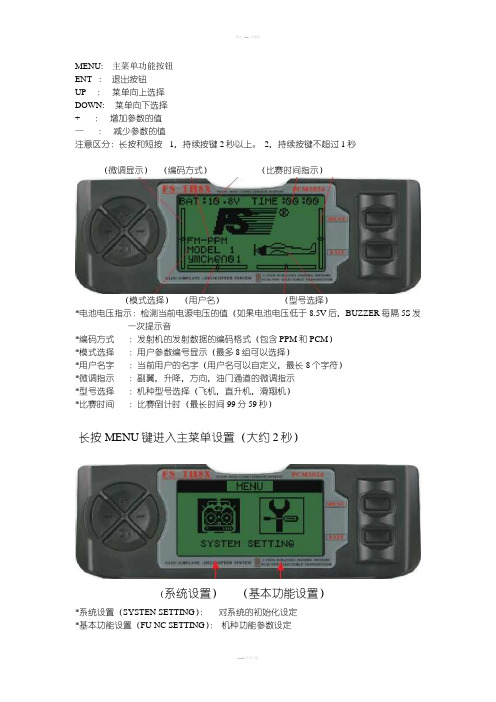
MENU: 主菜单功能按钮ENT : 退出按钮UP :菜单向上选择DOWN: 菜单向下选择+ :增加参数的值—:减少参数的值注意区分:长按和短按1,持续按键2秒以上。
2,持续按键不超过1秒(微调显示)(编码方式)(比赛时间指示)(模式选择)(用户名)(型号选择)*电池电压指示:检测当前电源电压的值(如果电池电压低于8.5V后,BUZZER每隔5S发一次提示音*编码方式:发射机的发射数据的编码格式(包含PPM和PCM)*模式选择:用户参数编号显示(最多8组可以选择)*用户名字:当前用户的名字(用户名可以自定义,最长8个字符)*微调指示:副翼,升降,方向,油门通道的微调指示*型号选择:机种型号选择(飞机,直升机,滑翔机)*比赛时间:比赛倒计时(最长时间99分59秒)长按MENU键进入主菜单设置(大约2秒)(系统设置)(基本功能设置)*系统设置(SYSTEN SETTING):对系统的初始化设定*基本功能设置(FU NC SETTING):机种功能参数设定*使用UP DOWN选择SYSTEN SETTING和(FU NC SETTING。
然后,短按(1秒左右)MENU确定进入相应菜单或者按EXIT键退出设置菜单*菜单每动作一次BUZZER发一次声音*如果是菜单中参数调到最大值后,继续按按钮,BUZZER将不会发出音系统设定功能*MODEL SELE :模式选择*MODEL NAME :用户名称编辑*TYPE SELE :机种型号的选择*MODEUAT :调制模式选择*STICK SET :控制杆的模式选择(左右手油门互换)*COPY :复制成初始化3-1模式选择(MODEL SELE)*功能说明:为不同机种的操作调出不同用户的设定*系统总共包含8种模式,也就是说能够存储8种不同形式的设置为不同的用户,每次使用只要选择它就能够调出相应的设置。
*使用UP DOWN按钮选择,如果选择第一项其他颜色会翻转*然后短按MENU选择保存并返回上一项菜单,按EXIT键不保存并返回上一项菜单)3-2用户名称编辑(MODEL NAME*功能说明:编辑用户的名称*使用UP ,DOWN按钮选择,如果选择某一项其颜色会翻转,使用(—),(+)选择不同的字符,包含有(数字,字母等,空格)。
三星 Galaxy S22 Ultra 用户手册说明书
SM-S9010SM-S9060SM-S9080HongKong China. 02/2022. Rev.1.0/hk目錄新手上路4 裝置結構圖與功能10 為電池充電15 SIM 或 USIM 卡 (nano-SIM 卡)17 開啟與關閉裝置18 初始設定19 三星帳戶20 從之前的裝置傳輸數據 (SmartSwitch)22 瞭解螢幕30 通知面板32 螢幕截圖與螢幕錄製33 輸入文字應用程式與功能36 安裝或解除安裝應用程式37 S Pen (Galaxy S22 Ultra)52 電話55 聯絡人57 訊息58 瀏覽器59 相機76 媒體瀏覽器80 AR 區域86 Bixby88 Bixby Vision 89 Bixby Routines91 多重視窗94 Samsung Pay96 Samsung Health97 Samsung Notes102 Samsung Members102 Samsung Kids103 Samsung Global Goals 103 Galaxy Shop103 Galaxy Wearable104 PENUP (Galaxy S22 Ultra) 104 日曆105 提醒106 錄音機107 我的檔案107 時鐘108 計算機108 遊戲中心109 Game Booster110 SmartThings110 分享內容112 音樂共享113 Smart View114 連結至 Windows115 Samsung DeX121 Google 應用程式目錄149 Google 150 進階功能151 動作與手勢152 視像通話效果153 Dual Messenger 154 數位健康與家長監護154 電池與裝置維護154 優化裝置155 電量155 儲存位置156 記憶體156 裝置保護156 軟件更新156 診斷156 應用程式157 一般管理158 協助工具158 軟件更新159 關於手機使用須知160 使用裝置的注意事項162 關於包裝內容與配件的說明163 抗水和防塵164 裝置過熱情況與解決方案附錄167 協助工具181 故障排除設定122 簡介122 三星帳戶122 連接124 Wi-Fi 125 藍牙126 NFC 與感應式付款128 數據節省器128 僅使用流動數據的應用程式128 流動熱點129 更多連接設定130 聲音和震動131 音質與音效131 分離應用程式聲音132 通知132 顯示133 動作流暢度134 變更螢幕模式或調整顯示色彩135 螢幕牆紙與樣式135 主題135 主螢幕135 鎖定螢幕136 Smart Lock 136 Always On Display 137 生物特徵與安全性138 臉部識別140 指紋識別142 Samsung Pass 144 安全資料夾147 私隱147 位置148 安全與緊急情況148 帳戶與備份149 三星雲端新手上路裝置結構圖與功能► Galaxy S22 Ultra:前置相機音量鍵側鍵SIM 卡匣揚聲器指紋識別感應器側鍵音量鍵觸控屏側屏幕側屏幕前置相機S PenSIM 卡匣話筒測距/光源感應器耳機插孔/多用途插孔 (USB Type-C)後置相機後置相機GPS 天線雷射 AF 感應器閃光燈主天線揚聲器話筒NFC 天線 / 無線充電線圈► Galaxy S22+, Galaxy S22:前置相機音量鍵側鍵SIM 卡匣揚聲器指紋識別感應器側鍵音量鍵觸控屏前置相機SIM 卡匣話筒耳機插孔/多用途插孔 (USB Type-C)測距/光源感應器後置相機後置相機閃光燈主天線話筒揚聲器GPS 天線NFC 天線 / 無線充電線圈•使用揚聲器時,比如播放媒體檔案或使用免提時,請勿將裝置放置於耳朵附近。
SJT-YBA-V13语音播报器用户手册说明书

SJT-YBA-V13 Voice Announcement DeviceUser ManualVer: V1.1ContentsPROLOGUE (2)1. Main Features (3)2. Structure Diagram and Principle (3)2.1 Principle (3)3. Configuration and Installation (4)3.1 Structure Diagram (4)3.2 Input terminals Definition (5)3.3 Wring diagram of serial communication system (5)4. Operation Instruction (6)4.1 The scope of floors broadcasting (6)4.2 The Language of Broadcasting (6)4.3 Broadcasting Welcoming Speech or Advertisement Words (6)4.4 Serial Mode Communication Setting (6)4.5 Select Arriving G ong Voice “Dingdong” (6)4.6 Door open/ close announcement function (7)4.7 Broadcasting Running Direction (7)4.8 The Announcement for Overload Function (7)4.9 The Announcement for Elevator in Fire Service Status (7)4.10 The Announcement for Elevator in Sliding Status (7)5. Commissioning Instruction (8)5.1 Setting Menu (8)5.2 Voice File Self-Studying (9)5.3 Indicator light status (9)5.4 Common Fault Handling (9)6. Ordering Information (10)Appendix I Update Instruction of Voice Files (10)Appendix II Voice Files Address List (11)PROLOGUESJT-YBA-V13 elevator voice announcement is an upgraded version of V12. V13 has the full functions of V12. This voice announcement system bases on the CAN cable elevator control system of our company. It doesn’t only have basic functions of general voice announcement, but also have simple wiring and configuration, nice appearance. The main technical characteristics are as follows:1.Adopting build-in FLASH memory voice module, the voice is in MP3 form, sound issimilar to CD. It is of better compatibility and smaller occupied capacity, and is easier to make. As the carrier of the voice file, the build-in FLASH memory has high performance, high security, and the voice update is very convenient, you only need to connect the module to computer with USB port.2.During the synthesis and record of voice, it adopts “GOLDWAVE” professional voicesoftware to process the audio. Special voice content could be composed by customer or our company. The procedure of realization of such function is only to input the voice files into the FLASH memory by the rules, which shortens the delivery time.3.SCM adopts STM8S208R8 of STMicroelectronics.1. Main Features∙Reliable performance, interference-free∙Convenient installation, commissioning-free∙Announcement of elevator running direction and floor2. Structure Diagram and PrincipleThe diagram of the SJT-YBA-V13 components is as follows:Figure 1 System Structure Diagram2.1 PrincipleThe shell of SJT-YBA-V13 elevator voice announcement is made of plastic. The main control MCU is STM8S208. WT2003 voice module transfer its inner voice files to analog voice signals through operational amplifier. It is transmitted to speaker, then gives out euphonic sound. All voice files are stored in the internal serial flash, and use USB port for file replacement.The working principle is as follows: after the voice announcement communicates with the elevator control system, it receives the elevator data through CAN bus in real time, and controls the voice chip to decode the audio file according to the landing information, and drives the speaker through the power amplifier circuit to realize the speech broadcast of the corresponding floor station.3. Configuration and Installation3.1 Structure Diagram3.1.1 DimensionsFigure 2 Plane layout3.1.2 Front and back layoutFigure 3 Front and back layout3.2 Input terminals Definition3.3 Wring diagram of serial communication systemThe upper part in Figure 4 is terminals on voice announcement device, the lower part is terminals of traveling cable, please connect them as shown in follows:+24V GND C+C-+24T GND1C+C-Terminal Block of Annoucement Traveling CableFigure 4 Wiring Diagram4. Operation Instruction4.1 The scope of floors broadcasting4.1.1 The standard broadcasting scope of this serial system announcement is:-3 ~ 50, B, G, B1, and B2. The explanation of those characters is:“G”: The Ground Floor;“B”: B floor;“B1”: Basement One;“B2”: Basement Two;4.1.2 When elevator reduces the speed and before stop at leveling, the device willannounce. For example: “arriving floor one”4.2 The Language of BroadcastingVoice A or Voice B can be changed by setting menu selection . Factory will build-in programming in the chip; the programming can be Chinese, or English, or Chinese with English.4.3 Broadcasting Welcoming Speech or Advertisement Words4.3.1 Trough the setting menu to select broadcasting or not welcomingspeech or advertisement.4.3.2 The serial system announcement will announce “welcome you to comein” after the door closed at base floor. We also can meet your special requirement for broadcasting content.4.4 Serial Mode Communication Setting4.4.1 Serial mode:Getting information from CAN bus4.5 Select Arriving Gong V oice “D ingdong”S elect broadcasting voice “dingdong” or not by setting menu.4.6 Door open/ close announcement function4.6.1 Select the door open/close announcement function or not by settingmenu.4.6.2 When system outputs door open signal, it announces voice “Open door”.After that, if the door open signal re-output, the voice will be announced again.4.6.3 when system outputs door close signal, it announces voice “Close door”,if there is car call been registered before door closing, it will announce running direction first, then announce “Close door”.4.7 Broadcasting Running Direction4.7.1 While door keeps open and there is a call registered, it will announceprepare running direction as “G oing up” or “G oing down”.4.7.2 When door is at closing process, there is door open signal comes fromdoor open button or door sensor, it will announce the running direction prepared gain.4.7.3 If the door keeps open, after announcing the running prepared direction,20 seconds later, it will be announced again.4.8 The Announcement for Overload Function4.8.1 If there is an overload signal; it will give a voice “car is overload now”.4.8.2 If the car always gets in overload status, it will announce “car is overload”in every 20 seconds.4.9 The Announcement for Elevator in Fire Service Status4.9.1 When elevator is in fire status, it will announce “fire alarm! Get outelevator immediately”4.9.2 If elevator is in fire status all long, it will announce the alarm voice inevery 20 seconds.4.10 The Announcement for Elevator in Sliding Status4.10.1 When elevator is in Sliding status, it will announce “Elevator fault! Getout elevator immediate ly”4.10.2 If elevator is in sliding status all long, it will announce the alarm voicein every 20 seconds.5. Commissioning Instruction5.1 Setting MenuSetting Mode:The voice station is installed successfully, after the power supply, you will hear " Operation mode ", in this state, long press the Menu key 3S and then release, you will hear the "setting mode", enter the set mode.In the setting mode, click the Menu button to switch the menu, click the Set button to switch settings options, menu and settings options have voice prompts, the specific content is as follows:Figure 5 Setting MenuOperation mode:In the setting mode, long press the Menu key 3S and then release, will hear the "operation mode" voice, enter the operation mode. If in the set mode, more than 60s, no key press, will automatically withdraw from the set mode, enter the operation mode.5.2 Voice File Self-StudyingWhen the voice station is installed successfully, Presse the Menu key and the Set key before the power is on, and then the power is switched on. When the green work light D6 blinks, release the Menu key and the Set key, voice file self-studying begins. [Note 1].After entering the voice file self-studying mode, the voice station will learn the file information in the WT2003 voice module. After changing the file information in the WT2003 voice module, it is necessary to do a voice file self-studying again.When the study is completed and successful, you will hear "voice file update success" [Note 2], and "operation mode". If the learning fails, it will not emit any sound, and the program reset.[Note: 1] rewriting voice station program, the next power will automatically enter into the voice file self-studying state; the voice station is connected with the computer through the USB data line, the next power will automatically enter into the voice file self-studying state.[Note: 2]If there is a configuration file in the voice file, the device will issue a voice: "The voice file is updated successfully, the configuration file is loaded successfully" or "The voice file is updated successfully, the configuration file is loaded failed" (the configuration file format is wrong).5.3 Indicator light statusThe Red Indicator light D7 constant ON: Power status is normal.The Green Indicator light D5 blink: CAN status is normal.The Green Indicator light D6:——Operation mode,Slow flashing (periodic 2s)。
PS690U系列保护测控装置技术使用说明书V1.3
2.11
修改 PST692U 整定控制字“中压侧复合电压” “低压 4
侧复合电压”,将其合并为“其他侧复合电压”
1.2
2.09
增加 PSV693U PSM695U 修正 PSV692U ST691UF 原理图
2
1.1
增加 PSC691U PSV692U PSM693U PSM694U
PST 691U变压器差动保护装置........................................................................................................................... 20 1 功能 .............................................................................................................................................................. 20 2 原理说明 ...................................................................................................................................................... 20 3 整定 .............................................................................................................................................................. 23
徐州重型用户手册简本

SCANRECO遥控器系统RC 400徐州重型机械股份公司操作手册2006年请把手册放在车辆上前言这个手册是作为整机使用说明书的补充,主要介绍Scanreco RC400遥控系统。
Scanreco RC400是十分先进的遥控系统,在控制速度的精确性上提供最大的安全性。
为了确保你的安全和机械的安全,你必须学习并掌握这个说明书里面的内容。
确保你可以更快地熟悉这个遥控系统,并且熟练地使用。
遥控器的操作人员:必须使用充分时间的来阅读以下两个章节:“系统描述”和“安全规章和操作说明”。
遥控器的设备安装人员:必须使用充分的时间来阅读以下两个章节:“安装说明书”,和“检查/安装文件”。
z遥控器只能由受过培训的人来操作。
操作人员在开始使用遥控器之前,必须认真的阅读并理解“安全规章和操作说明”的内容!如果没有按照说明书的要求去操作,后果很严重!z为了保护发射器不被损坏,以及安全的原因,发射器要必须保存在锁上的驾驶室里面。
z根据整机说明书的要求来操作遥控器。
z根据Scanreco的推荐(本手册),采购者有责任确定RC400是否适合这个应用,安装,以及符合地区的规章,条例。
z如果Scanreco的产品是使用在一个安全临界的应用,操作人员必须承担适当的实验和评估来阻止对最终使用者的伤害。
z未经授权,不能擅自改动Scanreco RC400!第一章系统描述1.1 Scanreco RC 400的图解遥控系统由以下部分组成:z便携式发射器(用于线控或无线遥控)z电子控制盒9线控操作:控制电缆(3芯)9无线操作:无线传输。
包括2块电池,电池充电器和无线接收盒1.2 便携式控制器带电池操作(无线控制)使用电池的便携式控制器可以实现无线操作,电池易于更换。
z一个电池的有效工作时间大约为8个小时。
z当电池需要充电时,控制器会发出三声作为警告,同时控制器上面的LED开始闪烁。
z电池最好使用到LED熄灭时,才进行替换。
如果电池电量太低,控制器无法工作。
软启动器使用说明书

软启动器使用说明书
一、用途
1.1 QJR系列矿用隔爆型真空交流软启动器适用于含有爆炸性气体(甲烷)和煤层的矿井中。
主要用于额定电压至1140V、660V,频率为50HZ的鼠笼型三相异步电动机的软启动、限流启动、双斜坡启动、全压启动、节能运行、软启动等功能。
是21世纪国家推荐使用的电子智能型新产品并于国际惯例接轨的国际项目。
启动器具有过载、过流、缺相、漏电闭锁、过电压、欠电压、温度保护等。
二,线路工作原理
2.1系统连接
参照电气原理图(以远控为例说明):接上远控按钮,合上隔离换相开关GHK,控制变压器KB1得电,控制与保护器QJ 及漏电闭锁组件K投入工作,若电源和负载都正常工作,即可开启启动器。
此时按下启动按钮,本安先导XD的固态继电器XJ1闭合,从而XJ2闭合,延时头继电器ZJ1和时间继电器SJ1\SJ2得电吸合,导线41与42通过ZJ1闭合而进入软启动状态,可控制按预先设定的模式结合现场条件,触发导通。
当软启动过程完毕后,切换触电闭合,中间继电器ZJ2 吸合,CJ吸合,旁路真空接触器投入运行,此时自保出点由ZJ1切换到CJ,整个启动过程完毕。
二、按键说明
三、菜单功能说明
七、指示灯说明
注:当A、V和%三个指示灯全灭时,当前显示内容为温度值。
软启动器出现故障时,RNU和STOP指示灯同时进行闪烁。
八、电气原件明细表。
胜家SE9150 SE9155 SE9180 SE9185 操作说明书
重要安全说明使用本电器时,务必遵守以下基本安全预防措施:请在使用此缝纫机前阅读所有说明。
将说明置于机器附近。
如将机器给予第三方,请确保将手册一并送予。
危险 - 要降低电击风险:缝纫机插上电源时,不得无人看管。
机器所插入的电源插座应该容易接近。
在使用后,清洁、打开机盖、润滑前,或者在进行说明手册中提到的其他任何维护调整时,请拔掉电源。
警告 - 要降低烫伤、火灾、电击或人身伤害风险:• 此设备供成人使用。
本电器可供(i) 8 至 12 岁的儿童以及(ii)身体、感官或心理能力较弱或缺乏经验和知识的人士在获得监督或指导安全使用电器的方法并明白相关危险的情况下使用。
在没有监督的情况下,儿童不可清洁和维修本电器。
不允许任何人玩这台机器。
8 岁以下的儿童不得使用本设备。
• 请勿将机器用作玩具。
缝纫机由儿童操作或在儿童附近使用时需特别注意。
• 仅按本手册所述指定用途来使用本缝纫机。
仅使用手册中制造商推荐附件。
• 切勿操作电源线或插头损坏、无法正常工作、跌落或损坏或者落入水中的缝纫机。
将缝纫机送至最近的授权经销商或维修中心进行检查、维修、电气或机械调整。
• 切勿在通风孔堵塞的情况下操作缝纫机。
保持缝纫机通风孔和脚踏控制器清洁,避免棉绒、灰尘和碎布积聚。
• 手指应远离所有活动部件。
在缝纫机针周围需要特别注意。
• 务必使用正确的针板。
错误的针板会导致机针折断。
• 请勿使用弯曲的机针。
• 请勿在缝纫时推拉布料。
否则可能会使机针偏斜,导致机针折断。
• 佩戴安全眼镜。
• 在机针区域进行机针穿线、换针、换底线或更换压脚等调整时,应转至“0”关闭机器。
• 切勿将任何物体丢进或插入通风口。
• 请勿在室外使用。
• 请勿在使用喷雾(喷撒)产品或氧气含量受控的环境下操作。
• 要断开机器,应将所有控制装置转至 (“0”) 位置,然后从插座中拔下插头。
• 拔下插头时请勿拉扯电源线。
要拔下插头,应抓住插头,而非电源线。
• 脚踏控制器用于操作机器。
V9系列微型基本DC切换器说明说明书

V9 SeriesMiniature Basic DC Switch DESCRIPTIONThe V9 Series dc switch is a cost-effective, reliable solution for position detection in applications that both control the primary circuit and require a contact air gap of greater than 3 mm [0.12 in]. The V9 Series dc switch offers a wide range of standard offerings, including a choice of seven actuators, global approvals (UL, cUL, ENEC/VDE), and two different quick-connect termination styles.FEATURES•> 3 mm [0.12 in] contact air gap •High electrical rating up to 25.1 A •Rock wipe contact action•Seven (7) standard actuators •Wide over-travel dimension •Long-life coil spring•Five (5) standard housing materialsBENEFITS•Enables user to control a primary circuit•Ability to directly control high electric loads•Self-cleaning operation delivers high reliability•Potential to solve a wide range of customer needs •Improves life of the switch by reducing potential mechanical damage to switch•Delivers enhanced reliability•Housing material options meet T85 °C to T200 °CPOTENTIAL APPLICATIONS•Power tools•Home appliances•Vending machines•Gaming equipment•Information technology equipmentV9 SeriesSPECIFICATIONSInsulation resistance (@ 500 Vdc)100 mOhm min.Dielectric strengthAC 1000 Vrms (50 Hz to 60 Hz) Contact resistance (initial) 30 mOhm max.Operating frequency – mechanical300 operations per minute max. Operating frequency – electrical 10 to 30 operations per minute max. Operating speed0,1 mm per 1 msec max. Service life – mechanical 5 million operations minimumService life – electrical 6,000 to 100,000 operations minimum Storage temperature -25 °C to 100 °C [-13 °F to 212 °F] Storage humidity85 %RH max.Approvals (apply to released options)UL, cUL, ENEC/VDEELECTRICAL RATINGS10cUL: 10 A 1/2 HP 125 Vac/250 Vac ENEC/VDE: 10(4) A 250 Vac T100 available11cUL: 10 A 1/2 HP 125 Vac/250 Vac ENEC/VDE: 4(3) A 250 Vac T125 available16cUL: 16 A 1/2 HP 125 Vac/250 Vac ENEC/VDE: 16(4) A 250 Vac T125 available20cUL: 20.1 A 1 HP 125 Vac/250 Vac ENEC/VDE: 20.1 A 250 Vac T125 available25cUL: 25 A 1 HP 125 Vac/250 VacENEC/VDE: 25.1 A, 10.1(8) A 250 Vac T125 availableOPERATING CHARACTERISTICSOF(g) max.Contact Gap > 3 mm* Part Number Lever/Position L S N OPmm [in]PT max.mm [in] OT min. mm [in] MD max. mm [in] A 190 510 395 14,4 ± 0,5 [0.57 ± 0.02] 1,90 [0.07] 0,70 [0.03] 1,20 [0.05] V9-*****D*00 Pin plunger B – – – – –––A 190 510 – 15,0 ± 0,8 [0.59 ± 0.03] 2,40 [0.09] 0,50 [0.02] 1,40 [0.05] V9-*****D*01 Short straight leverB 135 295 – 15,0 ± 1,2 [0.59 ± 0.05] 4,10 [0.16] 0,90 [0.04] 1,70 [0.07] A 100 260 – 15,0 ± 1,52 [0.59 ± 0.06] 4,80 [0.19] 1,00 [0.04] 2,70 [0.11] V9-*****D*02 Std straight lever B 80 150 – 15,0 ± 2,32 [0.59 ± 0.09] 8,00 [0.31] 1,70 [0.07] 3,30 [0.13] A 52 140 – 15,0 ± 2,82 [0.59 ± 0.11] 9,00 [0.35] 1,87 [0.07] 5,07 [0.20] V9-*****D*03 Long straight lever B 46 80 – 15,0 ± 4,32 [0.59 ± 0.17] 15,0 [0.59] 3,18 [0.13] 6,20 [0.24] A 108 290 – 18,4 ± 1,3 [0.72 ± 0.05] 4,30 [0.17] 0,90 [0.04] 2,40 [0.09] V9-*****D*04 Sim. roller lever B 88 170 – 18,4 ± 2,0 [0.72 ± 0.08] 7,20 [0.28] 1,50 [0.06] 2,90 [0.11] A 190 510 – 20,4 ± 0,7 [0.80 ± 0.03] 2,20 [0.09] 0,40 [0.02] 1,20 [0.05] V9-*****D*05 Roller lever B 145 330 – 20,4 ± 1,0 [0.80 ± 0.04] 3,70 [0.15] 0,80 [0.03] 1,50 [0.06] A 102 275 – 20,4 ± 1,4 [0.80 ± 0.06] 4,50 [0.18] 0,90 [0.04] 2,60 [0.10] V9-*****D*06Long roller leverB 84 160 – 20,4 ± 2,2 [0.80 ± 0.09]7,60 [0.30]1,60 [0.06]3,10 [0.12]PART NUMBER TREE2 /sensingMiniature Basic DC Switch MOUNTING DIMENSIONSmm [in] (for reference only)CIRCUITRY MOUNTING HOLESLEVER (ACTUATOR) MOUNTING POSITIONTERMINAL TYPESQuick connect terminal 0.187 in [4,75 mm] (D8) Quick connect terminal 0.250 in [6,35 mm] (D9)LEVER TYPESShort lever Standard leverLong lever Simulated roller leverRoller lever Long roller leverHoneywell Sensing and Control 3ORDER GUIDE (ACTIVE LISTINGS)Catalog Listing DescriptionV9-11S43D800 V9 miniature basic switch – pin plunger, 10 A 125/250 Vac, 0.187 x 0.032 QC terminals V9-16S23D800 V9 miniature basic switch – pin plunger, 10 A 125/250 Vac, 0.187 x 0.032 QC terminalsV9-16S43D905A V9 miniature basic switch – roller lever (slot far from pin plunger), 10 A 125/250 Vac, 0.250 x 0.032 QC terminalsV9-20S23D900 V9 miniature basic switch – pin plunger, 20.1 A 125/250 Vac, 0.250 x 0.032 QC terminals V9-20S43D900V9 miniature basic switch – pin plunger, 20.1 A 125/250 Vac, 0.250 x 0.032 QC terminals V9-25N23D900 V9 miniature basic switch – pin plunger, 25 A 125/250 Vac, 0.250 x 0.032 QC terminals V9-25S43D800 V9 miniature basic switch – pin plunger, 25 A 125/250 Vac, 0.187 x 0.032 QC terminalsV9-25S43D906A V9 miniature basic switch – roller lever (slot far from pin plunger), 25 A 125/250 Vac, 0.250 x 0.032 QC terminalsWARNINGPERSONAL INJURYDO NOT USE these products as safety or emergency stop devices or in any other application where failure of the product could result in personal injury.Failure to comply with these instructions could result in death or serious injury.Automation and Control Solutions Sensing and Control Honeywell1985 Douglas Drive North Minneapolis, MN 55422 /sensing 004943-1-EN IL50 GLO Printed in USA August 2006© 2006 Honeywell International Inc.WARRANTY/REMEDYHoneywell warrants goods of its manufacture as being free of defective materials and faulty workmanship. Honeywell’sstandard product warranty applies unless agreed to otherwise by Honeywell in writing; please refer to your orderacknowledgement or consult your local sales office for specific warranty details. If warranted goods are returned to Honeywell during the period of coverage, Honeywell will repair or replace, at its option, without charge those items it finds defective. The foregoing is buyer’s sole remedy and is in lieu of all other warranties, expressed or implied, including those ofmerchantability and fitness for a particular purpose. In no event shall Honeywell be liable for consequential, special, or indirect damages.While we provide application assistance personally, through our literature and the Honeywell web site, it is up to the customer to determine the suitability of the product in the application.Specifications may change without notice. The information we supply is believed to be accurate and reliable as of this printing. However, we assume no responsibility for its use.WARNINGMISUSE OF DOCUMENTATION• The information presented in this product sheet is forreference only. Do not use this document as a product installation guide.• Complete installation, operation, and maintenanceinformation is provided in the instructions supplied with each product.Failure to comply with these instructions could result in death or serious injury.SALES AND SERVICEHoneywell serves its customers through a worldwide network of sales offices, representatives and distributors. Forapplication assistance, current specifications, pricing or name of the nearest Authorized Distributor, contact your local sales office or:E-mail:*********************Internet: /sensing Phone and Fax:Asia Pacific +65 6355-2828 +65 6445-3033 Fax Europe +44 (0) 1698 481481 +44 (0) 1698 481676 Fax Latin America +1-305-805-8188+1-305-883-8257 Fax USA/Canada +1-800-537-6945+1-815-235-6847 +1-815-235-6545 Fax。
KJ90NB安全监控系统操作说明书
ISO9001:2001认证企业中煤科工集团重庆研究院KJ90N瓦斯监控系统操作说明书中煤科工集团重庆研究院目录目录 (2)第一章系统概述 (5)1.1 分院简介 (5)1.2 版本发布说明 (6)1.3 系统要求 (6)1.3.1 系统硬件最低要求: (6)1.3.2 系统软件环境要求: (6)1.4软件安装 (7)1.5术语约定及解释 (7)第二章中心站软件 (8)2.1 中心站主界面 (8)2.1.1 菜单与功能入口 (9)2.1.2 实时数据导航区 (9)2.1.2.1 按监测类型组织数据 (10)2.1.2.2 按区域组织数据 (11)2.1.2.3 按状态类型组织数据 (11)2.1.2.4 按自定义编排组织数据 (11)2.1.3 实时数据显示区 (12)2.1.4 信息监视区 (15)2.1.4.1 设备监视窗 (18)2.1.4.2 开关量运行监视窗 (18)2.1.4.3 模拟量报警监视窗 (18)2.1.4.4 实时曲线监视窗 (19)2.1.4.5 重点监视窗 (22)2.1.4.6 运行日志监视窗 (22)2.1.4.7 瓦斯预警监视窗 (22)2.1.5 状态显示区 (23)2.2 系统设置 (25)2.2.1 修改密码 (25)2.2.2 系统设置 (26)2.2.3 设备管理 (30)2.2.4 逻辑点管理 (41)2.2.5 抽放逻辑定义 (44)2.2.6 风电瓦斯闭锁控制 (46)2.2.7 控制 (48)2.2.7.1 手动断电控制 (48)2.2.7.2 分站复位 (49)2.2.7.3 时钟同步 (50)2.2.8 其他管理 (50)2.2.8.1 班次设置 (50)2.2.8.2 区域地址管理 (51)2.2.8.3 开关量值管理 (53)2.2.8.4 安标信息管理 (56)2.2.8.5 应急预案管理 (56)2.2.9 用户管理 (57)2.2.9.1 用户管理 (57)2.2.9.2 角色管理 (59)2.2.10 操作日志 (61)2.2.11 系统自诊断 (61)2.2.12 注销登录 (61)2.2.13 退出系统 (62)2.3 视图 (62)2.3.1自定义编排 (63)2.3.2 显示样式定义 (64)2.4 实时列表显示 (67)2.4.1 数据回放 (67)2.4.2模拟量报警 (68)2.4.3模拟量断电 (71)2.4.4模拟量馈电异常 (71)2.4.5模拟量调用 (72)2.4.6开关量报警 (74)2.4.7开关量断电 (74)2.4.8开关量馈电异常 (74)2.4.9开关量调用 (75)2.4.10设备故障显示 (75)2.4.11实时馈电异常 (76)2.5 矢量图 (76)2.5.1 图形展示 (76)2.5.2 图形编辑 (78)2.6 图形图表 (82)2.6.1 模拟量单点曲线 (82)2.6.2 模拟量多点曲线 (84)2.6.3 开关量状态图 (85)2.6.4 开关量柱状图 (86)2.7 查询统计 (87)2.7.1 模拟量报警 (88)2.7.2 模拟量断电 (89)2.7.3 模拟量馈电异常 (89)2.7.4 模拟量运行记录 (90)2.7.5 开关量报警 (90)2.7.6 开关量断电 (90)2.7.7 开关量馈电异常 (91)2.7.8 开关量状态变动记录 (91)2.7.9 开关量运行记录 (92)2.7.10 设备故障查询 (92)2.7.11 设备定义信息查询 (93)2.7.12 模拟量统计日报表 (94)2.7.13 模拟量统计值记录查询 (94)2.7.14 抽放报表查询 (95)2.8 帮助 (95)2.8.1 查看帮助 (96)2.8.2 产品主页 (96)2.8.3 系统注册 (96)2.8.4 技术支持 (96)2.8.5 安装信息 (96)2.8.5.1 设备类型 (96)2.8.5.2 功能安装 (96)2.8.5.3 地址类型管理 (96)2.8.5.4 菜单管理 (97)2.8.6 关于系统 (99)第一章系统概述1.1 分院简介中煤科工集团重庆研究院位于西南重镇、中国最年轻的直辖市——重庆市的科技文化区——沙坪坝区。
三星9-12NKUA_II空调用户手册说明书

No.Accessories partQty.1Installation plate12Installation plate fixing screw 53Remote Control 14Battery2No.Accessories partQty.5Remote controlholder16Remote control holderfixing screw 27Air purifying filter1Applicable piping kit Piping sizeGasLiquid CZ-3F5, 7BP 3/8" (9.52 mm)1/4" (6.35 mm)CZ-4F5, 7, 10BP 1/2" (12.7 mm)1/4" (6.35 mm)CZ-52F5, 7, 10BP5/8" (15.88 mm)1/4" (6.35 mm)Model Capacity (Btu/h)Piping sizeStd. Length (ft)Max. Eleva-tion (ft)Min. Piping Length (ft)Max. Piping Length (ft)AdditionalRefrigerant(oz/ft)PipingLengthfor add.gas (ft)Gas Liquid S9NKUA85003/8"1/4"24.649.29.865.60.224.6S12NKUA120001/2"49.29.865.60.224.6•IMPORTANTThis product has been designed and manufactured to meet ENERGY STAR ® criteria for energy effi ciency when matched with appropriate coil components. However,proper refrigerant charge and proper air fl ow are critical to achive rated capacity and effi ciency. Installation of this product should follow the manufacturer’s refrigerant charging and air fl ow instructions. Failure to con fi rm proper charge and air fl ow may reduce energy ef fi ciency and shorten equipment life.F615167•Read the following “SAFETY PRECAUTIONS” carefully before installation.•Electrical work must be installed by a licensed electrician. Be sure to use the correct rating of the power plug and main circuit for the model to be installed. •The caution items stated here must be followed because these important contents are related to safety. The meaning of each indication used is as below.Incorrect installation due to ignoring of the instruction will cause harm or damage, and the seriousness is classifi ed by the following indications.The items to be followed are classifi ed by the symbols:Carry out test running to confi rm that no abnormality occurs after the installation. Then, explain to user the operation, care and maintenance as statedin instructions. Please remind the customer to keep the operating instructions for future reference.Required tools for Installation WorksPlease follow the steps below to take out front grille if necessary such as when servicing.1. Set the vertical airfl ow direction louvers to the horizontal position.2. Slide down the 2 caps on the front grille as shown in the illustration at right, and then remove the 2 mounting screws.3. Pull the lower section of the front grille towards you to remove the front grille.•Open front panel and remove air fi lters.(Drainage checking can be carried out without removing thefront grille.)•Pour a glass of water into the drain tray-styrofoam.•Ensure that water fl ows out from drain hose of the indoor unit.•Operate the unit at cooling operation mode for fi fteen minutes or more.•Measure the temperature of the intake and discharge air. •Ensure the difference between the intake temperature andthe discharge is more than 46.4°F .1 Philips screw driver2 Level gauge3 Electric drill, hole core drill (ø2 3/4")4 Hexagonal wrench (5/32")5 Spanner6 Pipe cutter7 Reamer8 Knife9 Gas leak detector 10 Measuring tape 11 Thermometer 12 Megameter13 Multimeter 14 T orque wrench 13.3 Ibf.ft 31.0 Ibf.ft 40.6 Ibf.ft47.9 Ibf.ft 73.8 Ibf.ft15 Vacuum pump16 Digital Micron Gauge1. Open the front panel.2. Remove the air fi lters.3. Put the air purifying fi lter into place as shown in illustration at right.When reinstalling the front grille, fi rst set the vertical airfl ow direction louver to the horizontal position and then carry out above steps 2 - 3 in the reverse order.face a different way.Attached accessoriesSAFETY PRECAUTIONSExample: For S9NKUAshould be 1.64 oz .... (32.8 - 24.6) ft x 0.2 oz/ft = 1.64 oz.INDOOR UNITOUTDOOR UNITDo not install the unit in excessive oil fume area such as kitchen,workshop and etc.There should not be any heat source or steam near the unit. There should not be any obstacles blocking the air circulation. A place where air circulation in the room is good. A place where drainage can be easily done.A place where noise prevention is taken into consideration. Do not install the unit near the door way.Ensure the spaces indicated by arrows from the wall, ceiling, fence orother obstacles.Recommended installation height for indoor unit shall be at least 8.2 ft.If an awning is built over the unit to prevent direct sunlight or rain, becareful that heat radiation from the condenser is not obstructed. There should not be any animal or plant which could be affected byhot air discharged.Keep the spaces indicated by arrows from wall, ceiling, fence or otherobstacles.Do not place any obstacles which may cause a short circuit of thedischarged air.If piping length is over the [piping length for additional gas], additionalrefrigerant should be added as shown in the table.SELECT THE BEST LOCA TIONIndoor/Outdoor Unit Installation DiagramPRINTED IN MALAYSIAENGLISHF615167HOW TO T AKE OUT FRONT GRILLEINST ALLA TION OF AIR PURIFYING FILTEREVALUA TION OF THE PERFORMANCECHECK THE DRAINAGECHECK ITEMSAUTO SWITCH OPERA TIONThe below operations will be performed by pressing the “AUTO” switch.1. AUTO OPERATION MODEThe Auto operation will be activated immediately once the Auto Switch is pressed and release before 5 sec..2. TEST RUN OPERA TION (FOR PUMP DOWN/SERVICING PURPOSE)The T est Run operation will be activated if the Auto Switch is pressed continuously for more than 5 sec. A “pep” sound will occur at the fi fth sec., in order to identify the starting of T est Run operation.3. REMOTE CONTROLLER RECEIVING SOUND ON/OFFThe ON/OFF of Remote controller receiving sound can be change over by the following steps: a) Press AUTO switch continuously until “pep pep pep pep” sound is heard (about 16 sec.).b) Release the Auto switch button.c) Press the remote controller “AC RESET” button once, “pep” sound will occur.d) P ress Auto switch again. Everytime Auto switch is pressed (within 60 sec. interval), remote controller receiving sound status will be reversed between ON and OFF .Long “peep” sound indicates that remote controller receiving sound is ON. Short “pep” sound indicates that remote controller receiving sound is OFF .Is there any gas leakage at fl are nut connections?Has the heat insulation been carried out at fl are nut connection?Is the connection cable being fi xed to terminal board fi rmly?Is the connection cable being clamped fi rmly?Is the drainage ok?(Refer to “Check the drainage” section)Is the earth wire connection properly done?Is the indoor unit properly hooked to the installation plate?Is the power supply voltage complied with rated value?Is there any abnormal sound?Is the cooling operation normal?Is the thermostat operation normal?Is the remote control’s LCD operation normal?Is the Air purifying fi lter installed?。
SJDZ操作说明

在本产品运行前请认真阅读本说明书,以避免给产品或其他设备带来损坏!SJDZ节电器使用说明书安徽三益电力技术一、简介本公司的专利技术产品稳压节电器,是针对传统节电器的缺点而设计,采纳最新高科技自耦补偿调控原理,通过稳压调控、电磁移相、电磁平稳变换等技术完美结合,大幅提高了节电效率,节电率平都可达10%-20%。
是目前最先进的高效节电器,适用于各类三相和单相用电设备。
二、用途稳压节电器,产品适用于集中操纵的照明灯光系统(如:超市、餐厅、饭馆、医院、学校、银行、展览馆、停车场、游乐场、便利商店、百货商店、办公大楼、各类工厂、广告灯箱、路灯、公路隧道等)和以三相异步电动机及单相电机为动力的用电设备(如冲压机、车床、铣床、磨床、搅拌机、输送带、造粒机、注塑机、油泵、水泵、工业缝纫机、风机、粉碎机、球磨机、制砖机、锯料机、纺织机等)。
三、型号说明SJDZ- □—□ / □单相/三相功率(KW)/电流(A)节电对象(Z照明型,T通用型,D动力型)专利产品型号四、结构原理稳压节电器踊跃提倡绿色环保理念,实现大幅提高节电成效与净化电网质量双重目标,针对目前电网实际运行参数,通过实时监测电器负载转变的情形,应用最优化操纵原理,自动操纵输出功率,操纵供给电器设备的功率为实际需要的功率,达到精准匹配。
提高电器设备的功率因数,降低线损,增大线路容量,提高系统用电效率,使电压平稳取得改善,减少电器设备附加损耗,延长电器设备的利用寿命,从而有效实现了系统综合节电。
五、要紧特点1、节电成效显著,本装置在电机空载时可将空载电流降低,使输入视在功率大大降低,专门是对可变负载的电机,平均节电率可达10%-20%。
提高电网功率因数,降低线损及变压器铜损。
2、具有降压启动功能,将起动电流操纵在额定电流的1-4倍之间,并持续可调。
可取代降压启动器,节约大量的有色金属,适用于不同工况用起动器,应用范围普遍。
减少了启动电流对电网的冲击和对电机及设备的冲击转矩,减少电机的损耗,从而降低了电机的工作温度,延长电机的利用寿命。
v9使用说明书

激光基础知识
一、激 光 激光是外来语,LASER、镭射;LASER=Light Amplification by Stimulated Emission of Radiation. 即受激放 大的光辐射。
20 世纪四大发明 原子能 半导体 计算机 激光
古代四大发明 指南针 造纸术 火药 印刷术
二、激光的诞生
3
纹 唇:洗唇线时可由唇角开始操作,由于唇部组织较敏感,治疗头可轻贴 色素部位以避免出现水疱。
纹 身:纹身可分为人工纹身和外伤性纹身 人工纹身有两种纹刺手法:一种是用一排针沾取色料刺入皮肤,绘 成不同图案、文字。另一种是用纹身机操作,不同颜色的纹身用的 色料不同。 1.青黑色纹身所用的颜料最多是黑墨(碳) 2.蓝色纹身所用的色素有靓蓝、蔚蓝或碳粉 3.红色纹身所用的色素一般是朱砂、胭脂红等 4.外伤性纹身继发于创伤,如近距离爆炸引起碳颗粒的击入;交 通意外时可引起油漆、塑料、金属以及灰尘、路石等颗粒被击 进皮肤内。如果是人工纹身须多次治疗,最后可达到满意的效 果。 对于外伤性纹身的特殊性,须注意下列事项: 1.创伤后尽可能早地摩擦或刮去皮肤表面的颗粒 2.如果事故发生皮肤感染,这时皮肤表面的色素颗粒一定要清除 掉。以愈合的创伤,可用激光机选择性祛除纹身颗粒,但皮肤 会轻微损伤。
1960 年 5 月 5 日,美国物理学家里曼的一项实验,受激辐射,一束深 红色的亮光从红宝石中射出,它的亮度是太阳表面的 4 倍。
三、激光的特性
(1)、单色性:保持光束能精确地聚焦到焦点上,得到很高的能量密度。 (2)、方向性:有效传输较长的距离同时还能保证聚焦,保持极高的能量
密度。 (3)、相干性:主要描述光波各部分的相位关系,应用于信息存储、光通
用 532nm 激光祛除棕红色素时,应用小的能量密度,即大光斑,近距离治 疗,色素层较深的采取多次治疗的方式,每次治疗的间隔不小于 2 个月。
迪欧电子产品说明书.pdf_1719168375.4787946

排线将电调和编程盒连通后,然后给电调接上电源,LCD 设定盒将显示出开机界面,按LCD 设定盒上任意按键,设定盒和电调开始建立通信,并显示“CONNECTING ESC” ,等待几秒后,将显示出当前的模式名 ,随后显示出第一个设置参数。
使用 “ITEM”和“VALUE” 按键即可更改设置参数,按“OK”键可将设置参数存入电调。
感谢您购买EZRUN-MAX8-V3车用无感无刷电机电子调速器!无刷动力系统功率强大,错误的使用可能造成人身伤害和设备损坏。
请在使用设备前仔细阅读说明书,严格遵守规定的操作程序。
我们不承担因使用本产品而引起的任何责任,包括但不限于对附带损失或间接损失的赔偿责任;同时我们不承担因擅自对产品进行修改所引起的任何责任。
我们有权在不经通知的情况下变更产品设计、外观、性能及使用要求。
参数说明3有以下几种恢复出厂参数方法:1)利用SET键恢复出厂设置,方法如下:在油门摇杆处于中立点位置的任意时刻(除进行油门校调或编程设定时),按住 SET 键3秒以上,可恢复出厂设定。
红绿灯同时闪烁时表示恢复设定成功,出厂设定需重新上电方 可生效。
2)利用LED参数设定卡恢复出厂设定:设定卡与电调连通后,按下“RESET”键,然后再按下“OK”保存,即可恢复出厂设置。
3)利用LCD多功能编程盒恢复出厂设定:设定卡与电调连通后,通过“ITEM”选项选到“RESTORE DEFAULT”项,然后再按下“OK”保存,即可恢复出厂设置。
1.启动阶段1)红灯持续快速闪烁:电调未检测到油门信号或电调内部存储的油门中点数值与遥控器不匹配。
2)绿灯闪烁N次:锂电节数检测,闪烁N次表示当前锂电为N节。
2.行驶阶段1)油门摇杆处于中点区域,红色和绿色LED均熄灭。
2)前进时,红色LED恒亮;当油门处于正向最大(100%油门)时,绿色LED也会点亮。
3)刹车时,红色LED恒亮;当油门处于反向最大且最大刹车力度设为100%时,绿色LED也会点亮。
- 1、下载文档前请自行甄别文档内容的完整性,平台不提供额外的编辑、内容补充、找答案等附加服务。
- 2、"仅部分预览"的文档,不可在线预览部分如存在完整性等问题,可反馈申请退款(可完整预览的文档不适用该条件!)。
- 3、如文档侵犯您的权益,请联系客服反馈,我们会尽快为您处理(人工客服工作时间:9:00-18:30)。
SJT-YBA电梯语音报站器V9版使用说明书沈阳蓝光自动化技术有限公司绪言SJT-YBA-V9电梯语音报站器,是我公司推出的V6版本的升级。
V9继承了V6版本的全部功能。
也是基于本公司CAN总线电梯控制系统的电梯语音报站系统;同时也兼容本公司及其他厂家生产的并行电梯控制系统。
它不但具有一般电梯语音报站器的基本功能,而且相应的接线、配置简单,外观精巧。
其主要技术特点有:1.采用SD卡型语音模块,语音为MP3 格式, 语音位速:56kbps,音质优美程度接近CD。
通用性好,占据容量小,容易制作。
SD 卡作为存储语音的载体,存储容量大,性能高,安全性高语音更新十分方便,只需SD 卡与电脑连接即可。
2.在产品的语音合成录制中,使用“GOLDWAVE”专业语音软件进行音效处理。
特殊语音播报用户可自行制作,也可以由本公司制作,只要将制作好的语音文件按照规定存于SD卡即可实现特殊语音播报功能,避免了V6版本修改程序的繁琐过程。
大大缩短供货时间。
3.单片机采用 freescale的MC68HC908GZ164.适用于本公司开发的CAN总线电梯控制系统以及并行信号输出电梯控制系统。
目录1.主要特点 (3)2.系统的结构框图及原理 (3)3.基本配置及安装 (4)4.使用说明 (6)5.调试说明........................................................................................... (8)6.包装、运输及保管 (8)7.订货须知 (8)附录:用户订货信息卡1.主要特点:∙工作可靠,抗干扰能力强∙安装方便,无须调试∙电梯运行方向、层站播报∙背景音乐播放∙根据用户需求进行广告播放等2.系统的结构框图及原理SJT-YBA-V9电梯语音报站器的元器件布局示意图如下所示:各部分说明如下:U1为单片机freescale的MC68HC908GZ16,SD语音模块将SD卡内的语音文件转化为模拟声音信号。
W1和W2为电位器,J1、J2和J3为接线端子, LS1为音箱插座,外接音箱可以是单声道,也可以是双声道。
D2为通讯灯,D3为电源指示灯,D1为CPU工作指示灯。
原理说明:背景音乐和语音播报内容都存储在SD卡内,SD型语音模块将其内部语音文件转化成模拟声音信号,经过外部运放传给外接音箱,发出悦耳的声音。
单片机freescale的MC68HC908GZ16及CAN接口电路82C250组成CAN 总线的硬件。
电梯语音报站器与电梯控制系统通讯后,单片机根据收到电梯到达的层站信息,进行相应层站的语音播报;并行控制系统通过光耦将楼层信号和运行信号输入到语音报站器,进行相应层站的语音播报。
3.基本配置及安装3.1结构图3.1.1俯视图图2 语音报站器俯视图3.1.2侧视图图3 侧视图3.2输入端子定义串行系统接线图:图4上方为语音报站器的接线端子,下方为轿厢随行电缆,请将语音报站器接线端子的+24与轿厢随行电缆的24T相连,GND与GND1相连,C+与C+相连,C-与C-相连。
图4 接线图4.使用说明4.1楼层报站播报范围:4.1.1标准串行系统播报范围为–3—50、B、G、B1、B2。
其中G中文播报:G楼到了;英文播报:The Ground Floor;其中B中文播报:B楼到了;英文播报:B floor;其中B1中文播报:地下1楼到了;英文播报:Basement One;其中B2中文播报:地下2楼到了;英文播报:Basement Two;4.1.2并行系统二进制位码、BCD码和格雷码的输入方式播报范围为–3—50楼;七段码方式的播报范围为–3—19楼4.1.3电梯运行到站换速后,在停靠前播报到站层语音,如“1楼到了”。
4.2播报楼层语音的语言种类:通过拨码开关设置选择两套不同的播报语音;语音芯片烧写时可为中文,英文或中英文播报。
4.3播报欢迎词或广告词:4.4.1通过拨码开关设置是否播报欢迎词或广告词。
4.4.2串行系统基站关门后播报欢迎词“欢迎乘坐电梯”,并行系统在1楼关门后播报欢迎词;也可根据客户的要求播报广告词和欢迎词。
4.4背景音乐播放和选择:4.4.1通过拨码开关可以选择有无背景音乐。
4.4.2电梯运行自动循环播放背景音乐;电梯进入停止运行或检修状态时,背景音乐不会立即停止,待该段音乐播完后不再播放。
4.4.3背景音乐语音芯片可储存多曲,在程序内部固定好曲目数后,电梯运行自动循环播放不同曲目背景音乐。
4.5并行或串行输入设置:4.5.1通过拨码开关设置播报信息并行或串行输入。
4.5.2串行输入:播报信号通过CAN总线通讯获得。
4.5.3并行输入:播报信号通过光耦并行输入,层站信号可选择为七段码、格雷码,二进制码、BCD码方式。
4.6叮咚语音播报设置通过拨码开关设置在播报到站前是否播报叮咚。
4.7开/关门语音播报:4.7.1通过拨码开关可以选择有无开/关门语音播报。
4.7.2电梯开门信号输出后播报“电梯开门”;电梯开门信号输出后如在次开门输出进行在次播报。
4.7.3电梯关门信号输出后播报“电梯关门”;如电梯有运行方向,先播报运行方向后在播报“电梯关门”。
4.8播报电梯运行方向4.8.1电梯开门并且有运行方向播报语音“电梯上行”或“电梯下行”.4.8.2关门时如按开门按钮或有安全触板开门信号重报方向语音。
4.8.3电梯一直处于开门状态时,播报方向后计时10秒重报方向语音。
4.9拨码开关设置说明BM1:✧BM2_1:拨到ON,进入系统自检模式,如果系统语音模块与语音播放电路正常,会发出“谢谢你测试我的声音”,否则不发声;在语音播放正常的前提下,系统的CAN 通讯正常,会发出“我的CAN通讯是正常的”,否则不发声。
自检模式用来判断语音报站器的通讯与播音功能。
正常应用时,必须设置为OFF。
✧拨码开关2:系统备用。
4.10电梯超载时播报提示语音4.10.1有超载信号时播报“电梯超载,请后来的乘客下一次乘坐”。
4.10.2电梯一直处于超载状态时,播报后计时20秒重报超载语音提示。
4.11电梯进入消防状态时播报提示语音4.11.1有消防信号时播报“大楼发生火灾,请乘客立即撤离电梯”。
4.11.2电梯一直处于消防状态时,播报后计时20秒重报消防语音提示。
5 调试说明5.1音量调整用螺丝刀调节电位器W1,W2,顺时针旋转音量增大,逆时针旋转则音量减小。
5.2指示灯状态语音报站器安装成功后,红色电源指示灯D3常亮,绿色工作指示灯D1闪亮,表示语音报站器正常工作,绿色通讯灯D2闪亮,表示通讯信号正常。
5.3常见故障处理(1)电源指示灯不亮,用万用表测量接线端子的“+24”和“GND”,如果不是24伏,请重新连接接线端子的“+24”和“GND”。
(2)指示灯不闪亮,请重新连接接线端子的“C+”和“C-”。
(3)如果指示灯状态均正常,但仍听不到语音播报或背景音乐,请检查音箱是否接好,或者检查音量是否调整到适中。
6.订货须知该语音报站器可以根据您的需要,提供您希望播放的语音信息。
为了方便您的使用,请您在定购语音报站器之前认真填写订货信息卡,我公司会根据您所提出的要求为您录制相应的语音音频文件。
附录:SD卡语音文件存储说明语音报站器的报站内容与当前楼层显示对应,而V9版语音报站器采用SD卡型语音模块,语音文件格式为MP3,存储内容按文件夹的形式编排,文件夹名称为advert+数字,从advert00, advert01advert,02------advert99,共100 个文件夹(以下省略advert),文件夹下的语音文件名称也为数字,从000,001,002------999,共1000 个语音文件。
单片机通过调用不同文件夹下的语音文件,实现丰富的语音播报功能。
为了方便存储,将楼层显示与语音存储位置的对应关系作如下介绍:为了阐述方便,这里用” AB”代表文件夹名,” CDE”代表文件夹内的语音文件名,这里A、B、C、D、E都表示数字,范围是0-9。
✧对于层站显示为两位字符而言,将每一位楼层显示字符(见楼层显示字符表中“楼层显示字符”)对应于一个两位数(见楼层显示字符表中“序号”),这样两位楼层显示字符就对应于一个4位十进制数(以下简称“X”),高两位对应高位楼层显示字符,低两位对应低位楼层显示字符。
“X”的低三位就是文件夹内的语音文件名,“X”的高位就是文件夹名的低位,文件夹名的高位这样规定:中文模式:高位为0,中英文模式,高位为1。
例如:中文报站,当前楼层显示为“15”,高位楼层显示字符“1”对应序号为“03”,低位楼层显示字符“5”对应序号为“07”,组成的4位数就是0307。
即X 为0307,因为是中文报站,所以文件夹名AB 为00,语音文件名CDE为307。
所以,15楼层显示对应的语音文件的存储位置为文件夹advert00下,文件名为307。
参见下图:同理:中英文报站,当前楼层显示为“HS”,高位楼层显示字符“H”对应序号为“19”,低位楼层显示字符“S”对应序号为“30”,组成的4位数就是1930。
即X 为1930,因为是中英文报站,所以文件夹名AB 为11,语音文件名CDE为930。
所以,HS楼层显示对应的语音文件的存储位置为文件夹advert11下,文件名为930.mp3。
✧对于三位楼层显示而言,文件夹名称为advert20,文件名与绝对楼层对应(最底层为0层)。
如某大楼的第9层(绝对楼层)为三位显示“UCW”,则语音文件的存储位置为文件夹advert20下,语音文件名为009.mp3。
三位楼层显示对应唯一语音文件,不区分中英文。
注意:1.在advert01 文件夹下有一个名称为”cof.mp3”的文件,这个文件必须保留。
也就是说无论advert01文件夹内是否有语音文件,这个文件夹及”cof.mp3”的文件都是要存在的。
2.在advert00 文件夹下有两个名称分别为”999.mp3”和”998.mp3”的文件,这两个文件必须保留。
也就是说无论advert00文件夹内是否有语音文件,这个文件夹着两个文件都是要存在的。
999.mp3为语音播报功能检测用,998.MP3为通讯测试用。
3.为了察看方便,可以在文件夹内文件名数字后面加上注释,注释跟前面的数字合起来作为文件名。
如:文件夹advert01下003.mp3语音文件可以这样定义:003_1楼.MP3。
这样就可以方便知道003语音文件是1楼到站时播放的语音。
4.对于SD卡存储空间暂作如下规划:✧advert00- advert09,作为中文(或英文)语音播报内容存放位置;✧advert10- advert19,作为中英文语音播报内容存放位置;✧advert20,作为三位楼层显示时播报内容存放位置;✧advert99,作为背景音乐内容存放位置;5.文件夹取名只能为advert00- advert99,文件内容可以在数字后加注释如:003_1楼.MP3。
