EasyARM-iMX283 硬件设计指导手册 V1.06
MaaXBoard IMX8M单板计算机用户手册V1.2说明书

MaaXBoard (EM-MC-SBC-IMX8M) Hardware User ManualV1.2Copyright Statement:The MaaXBoard single board computer (partnumber: EM-MC-SBC-IMX8M) and its relatedintellectual property are owned by Avnet Manufacturing Services.Avnet Manufacturing Services has the copyright of this document and reserves all rights. Any part ofthe document should not be modified, distributed or duplicated in any approach and form with the written permission issued by Avnet Manufacturing Services.Disclaimer:Avnet Manufacturing Services does not take warranty of any kind, either expressed or implied, as tothe program source code, software and documents provided along with the products, and including, but not limited to, warranties of fitness for a particular purpose; The entire risk as to the quality or performance of the program is with the user of products.Regulatory Compliance:MaaXBoard single board computer has passed the CE, FCC & SRRC certification.Revision HistoryRev. Description Author DateV1.0 Update description Hugo 20190815Hugo 20191121 V1.1 Update block diagram, picture anddescriptionV1.2 Add SRRC description Hugo 20200527CatalogRevision History (3)Chapter 1Product Overview (8)1.1Brief Introduction (8)1.2System Block Diagram (8)1.3Packing List (9)1.4Product Specifications (9)1.5Other Customer Provide Parts (10)1.6Interface Locations (11)1.7Product Dimensions (mm) (12)1.8Height Distribution (mm) (13)Chapter 2Introduction of Hardware System (14)2.1MaaXBoard Hardware Installation and Start up (14)2.1.1Installation (14)2.1.2Booting Configuration (14)2.2Details of Interfaces (15)2.2.1POWER IN (15)2.2.2Button (16)2.2.3HDMI (17)2.2.4USB Host (19)2.2.5RJ-45 (21)2.2.6Camera (23)2.2.740 Pin Expansion Pin Header (26)2.2.8Wi-Fi/Bluetooth (Optional) (30)2.2.9Micro SD Card (TF Card) (32)2.2.10Extend Interface J26 (34)2.2.11Extend Interface J23 (36)2.2.12MIPI-DSI (37)2.3Introduction of Peripheral Chips (40)2.3.1AR8035 (40)2.3.2BD71837 (40)2.3.3AW-CM256SM (40)Chapter 3Appendix (41)3.1Software (41)Chapter 4Technical Support and Warranty (42)4.1Technical Support (42)4.2Warranty Conditions (42)Chapter 5Contact Information (44)FigureFigure 1.1 MaaXBoard System Block Diagram (8)Figure 1.2 MaaXBoard Top View (11)Figure 1.3 MaaXBoard Bottom View (11)Figure 1.4 Product Dimensions (12)Figure 1.5 Height Distribution (13)Figure 2.1 USB Type C Slot (15)Figure 2.2 Button (16)Figure 2.3 HDMI Connector (17)Figure 2.4 Double-layer USB Host connector (19)Figure 2.5 RJ45 Connector (21)Figure 2.6 Camera Connector (23)Figure 2.7 2.54mm Double Row Pin Header (26)Figure 2.8 40Pin Pin Header Pin1 Position (27)Figure 2.9 IPEX Antenna Connector (30)Figure 2.10 Onboard Ceramic Antenna (31)Figure 2.11 Micro SD Card Slot (32)Figure 2.12 12Pin Wafer Connector (34)Figure 2.13 12Pin Wafer Connector (36)Figure 2.14 30 Pin FPC Connector (MIPI-DSI) (37)TableTable 2.1 HDMI Pin Definitions (18)Table 2.2 USB Interface Pin Definition (20)Table 2.3 Ethernet Interface Pin Definition (22)Table 2.4 Camera Connector Pin Definition (24)Table 2.5 40 Pin Expansion Pin Header Definition (27)Table 2.6 Antenna Connector Pin Definition (30)Table 2.7 Micro SD Card Slot Pin Definition (33)Table 2.8 12Pin Definition (35)Table 2.9 J23 Pin Definition (36)Table 2.10 J16 Pin Definition (38)Chapter 1 Product Overview1.1 Brief IntroductionMaaXBoard is a development board for makers, designed by Avnet Manufacturing Services. The MaaXBoard is a single board computer based on NXP IMX8M SOC series, which can be used for the areas such as medical instruments, video surveillance, communications, IOT, makers and so on.In the design of a compact body size, it is provided with rich resources of peripheral interface, include: Gigabit Ethernet interface, USB 3.0 interface, MIPI-DSI interface, MIPI-CSI interface, HDMI interface, Micro SD Card interface, UART interface, GPIO interface, Wi-Fi/Bluetooth interface, etc.1.2 System Block DiagramFigure 1.1 MaaXBoard System Block Diagram1.3 Packing List1 ×MaaXBoard1 × Desiccant1 × Anti-static Bag1 × Safety Flyer1 × Quick Start Guide2 × Electrostatic Foam1 × Box1.4 Product SpecificationsGeneral Specifications:Operating Temperature: 0~70°C (When the CPU loads heavy, need a heatsink)Power Supply: 5V/3A (Power Adapter)Operating Humidity: 20% ~ 90% (non-condensing)Dimensions: 85mm × 55mmPCB Layers:10LayersCommunication Interface:1 × 40 Pin IO Interface (Expand I2C, SPI, UART, I2S Interface)1 × MIPI-CSI Camera Interface1 × MIPI-DSI Display Interface1 ×Gigabit Ethernet interface (RJ45)2 × USB3.0 Host1 × Micro SD Card (TF Card) Interface1 × 8bits and 1x 7bits GPIO Interface (Support Audio peripheral expand)1 × HDMI 2.0 Interface1 × Power Interface (USB Type C Connector)1 × Power Button2 × User Button1 × Wi-Fi/Bluetooth2 × User LED1.5 Other Customer Provide PartsTo use the various functions of MaaXBoard, customer should also provide the following parts which are not contained in MaaXBoard Packages.1 × USB to serial cable (TTL)1 × 1Gbps Network Cable1 × Camera Module1 × MIPI-DSI Displayer1 × 5V/3A Power Supply (USB Type C Interface)1 × HDMI Cable1 × HDMI DisplayerOther tools needed to implement related function1.6 Interface LocationsFigure 1.2 MaaXBoard Top ViewFigure 1.3 MaaXBoard Bottom View1.7 Product Dimensions (mm)Figure 1.4 Product Dimensions1.8 Height Distribution (mm)Figure 1.5 Height Distribution Note: There is tolerance in height due to mechanical treatment.Chapter 2 Introduction of Hardware SystemThis chapter will introduce the structure, expansion and peripheral interfaces of MaaXBoard hardware system in details.2.1 MaaXBoard Hardware Installation and Start upBefore power up MaaXBoard, you need to connect all necessary peripheral devices, then power on the board.According to the manufactured configuration, MaaXBoard supports two boot mode: boot from Micro SD card or boot from eMMC. These two boot mode is mutual exclusion. If users choose to boot from Micro SD card, they should burn the latest image to the card on PC, then install the card to the board, refer to the software user manual. If users choose to boot from eMMC, just power on the board.Note: If the eMMC firmware is destroyed by accident, users could update the eMMC image in USB Download mode. Please operate carefully and follow the steps in software user manual strictly to avoid damaging the product.2.2 Details of InterfacesThis section will introduce the constructions, principles, interface definitions and considerations of use of MaaXBoard peripherals in detail, so that users may have a deep understanding of the hardware circuitry of the board.MaaXBoard use a USB Type C interface as the +5V power in. Note that the USB Type C interface only provides power supply function, do not support data communication.The Power adapter should support 3A or above current output.Figure 2.1 USB Type C SlotThere are 3 buttons on the MaaXBoard, S2 as the system power button for the board, S3 and S4 as user button.Figure 2.2 ButtonPowerful video display is an important feature of MaaXBoard. The HDMI 2.0 interface support up to 4096 x 2160 at 60Hz display output.J9 is the interface for connecting an HDMI display device on the MaaXBoard, which is a standard HDMI 19Pin connector. Its specification and dimension as follows:Figure 2.3 HDMI ConnectorTable 2.1 HDMI Pin DefinitionsMaaXBoard provides a Double-layer USB Host connector (J5), the two USB port are two independent controllers, and each one could provide full speed USB3.0 data communication function, used to extend external devices in USB protocol.Figure 2.4 Double-layer USB Host connectorTable 2.2 USB Interface Pin DefinitionJ13 is the physical interface of Gigabit Ethernet, the interface information is shown in the following picture:Figure 2.5 RJ45 ConnectorTable 2.3 Ethernet Interface Pin DefinitionJ12 on the MaaXBoard is a 30-pin FPC connector that supports MIPI 2Lane Camera input. The following picture shows the information of J12:Figure 2.6 Camera ConnectorTable 2.4 Camera Connector Pin DefinitionJ10 on the MaaXBoard is a 40 pin Extend Interface, used to support external devices. The following picture shows the information of the 40 Pin expansion connector J10:Figure 2.7 2.54mm Double Row Pin HeaderFigure 2.8 40Pin Pin Header Pin1 Position Table 2.5 40 Pin Expansion Pin Header DefinitionMaaXBoard employs a Wi-Fi/Bluetooth module to support Wi-Fi 2.4G/5G Frequency, and Bluetooth V4.2 standard. The Wi-Fi/Bluetooth antennas have two type: onboard ceramic antenna or IPEX antenna.IPEX antenna (customized version)IPEX antenna is empty welding in default, if the customer needs to use this interface, please contact the Avnet Manufacturing Services to customize.IPEX antenna connector’s specification as follows:Figure 2.9 IPEX Antenna ConnectorTable 2.6 Antenna Connector Pin DefinitionOnboard Ceramic Antenna (Default)Onboard Ceramic Antenna’s specification as follows:Figure 2.10 Onboard Ceramic AntennaMicro SD card (TF Card) is used to start the code, the program system curing storage, or provide external storage function.Figure 2.11 Micro SD Card SlotTable 2.7 Micro SD Card Slot Pin DefinitionJ26 on the MaaXBoard is a 12 pin Wafer connector, used to support GPIO function. The following picture shows the information of the 12 pin Wafer connector J26:Figure 2.12 12Pin Wafer ConnectorTable 2.8 12Pin DefinitionJ23 on the MaaXBoard is a 12 pins Wafer connector, used to support GPIO function. The following picture shows the information of the 12 pins Wafer connector J23:Figure 2.13 12Pin Wafer ConnectorTable 2.9 J23 Pin DefinitionJ16 on the MaaXBoard is a 30 pin FPC connector that supports MIPI-DSI high-definition and small size screen.The following picture shows the information of 30-pin FPC connector J16:Figure 2.14 30 Pin FPC Connector (MIPI-DSI)Table 2.10 J16 Pin Definition2.3 Introduction of Peripheral ChipsAR8035 Integrated 10/100/1000 Mbps Ethernet Transceiver. The AR8035 is a single port 10/100/1000 Mbps Tri-speed Ethernet PHY, which provides a low power, low BOM (Bill of Materials) cost solution for comprehensive applications including consumer, enterprise, carrier and home networks, etc.AR8035 supports IEEE 802.3az Energy Efficient Ethernet (EEE) standard and Atheros proprietary SmartEEE, which allows legacy MAC/SoC devices without 802.3az support to function as the complete 802.3az system.BD71837MWV integrated all the power voltage for iMX8M, include the peripheral power voltage, which significantly reduce the difficulty when customer develop the system, shorten the development cycle and the manufacture period of the product.BD71837MWV is Power Management IC specially designed for iMX8M by ROHM Semiconductor. It integrates 8 Buck regulators and 7 LDOs, support the processor to dynamically adjust the power to achieve the goal of energy saving. The chip provides 1.8V/3.3V optional MMC card power supply at the same time. Users could choose 1.8V or 3.3V output by change the resistor, to fit multimedia card with various type and protocol. It provides a 32.768 kHz Crystal Oscillator Driver which could power to the clock circuit directly. It also provides several protection modes: output short circuit, output overvoltage/current, over thermal protection, etc.The AW-CM256SM wireless module is compliant with the IEEE 802.11a/b/g/n/ac standard, support connection up to 433.3Mbps transmit/receive (connect to WLAN using 802.11 ac protocol).AW-CM256SM module provide SDIO interface Wi-Fi, UART/PCM interface Bluetooth Function. It enables a low power consumption and high performance solution that fit for IOT and other application field.Chapter 3 Appendix3.1 SoftwareMaaXBoard support Linux Yocto system and Android system, for the detail software introduction, please refer to related user manual.LinuxMaaXBoard Linux Software Release NoteMaaXBoard Linux Software User ManualMaaXBoard Linux Software Development GuideAndroidMaaXBoard Android Software Release NoteMaaXBoard Android Software User ManualMaaXBoard Android Development GuideChapter 4 Technical Support and Warranty4.1 Technical SupportAvnet Manufacturing Services provides its product with one-year free technical support including:Providing software and hardware resources related to the embedded products of AvnetManufacturing Services;Helping customers properly compile and run the source code provided by Avnet ManufacturingServices;Providing technical support service if the embedded hardware products do not function properlyunder the circumstances that customers operate according to the instructions in the documents provided by Avnet Manufacturing Services;Helping customers troubleshoot the products.The following conditions will not be covered by our technical support service. We will take appropriatemeasures accordingly:Customers encounter issues related to software or hardware during their development process;Customers encounter issues caused by any unauthorized alter to the embedded operatingsystem;Customers encounter issues related to their own applications;Customers encounter issues caused by any unauthorized alter to the source code provided byAvnet Manufacturing Services.4.2 Warranty Conditions12-month free warranty on the PCB under normal conditions of use since the sales of the product;The following conditions are not covered by free services; Avnet Manufacturing Services will chargeaccordingly:Customers fail to provide valid purchase vouchers or the product identification tag is damaged,unreadable, altered or inconsistent with the products;Not according to the user's manual operation causes damage to the product;Products are damaged in appearance or function caused by natural disasters (flood, fire,earthquake, lightning strike or typhoon) or natural aging of components or other force majeure;Products are damaged in appearance or function caused by power failure, external forces, water,animals or foreign materials;Products malfunction caused by disassembly or alter of components by customers or, productsdisassembled or repaired by persons or organizations unauthorized by Avnet ManufacturingServices, or altered in factory specifications, or configured or expanded with the componentsthat are not provided or recognized by Avnet Manufacturing Services and the resulted damage in appearance or function;Product failures caused by the software or system installed by customers or inappropriatesettings of software or computer viruses;Products purchased from unauthorized sales;Warranty (including verbal and written) that is not made by Avnet Manufacturing Services andnot included in the scope of our warranty should be fulfilled by the party who committed. Avnet Manufacturing Services has no any responsibility.Within the period of warranty, the freight for sending products from customers to AvnetManufacturing Services should be paid by customers; the freight from Avnet Manufacturing Services to customers should be paid by us. The freight in any direction occurs after warranty period should be paid by customers;Please contact technical support if there is any repair request.Avnet Manufacturing Services will not take any responsibility on the products sent backwithout the permission of the company.Chapter 5 Contact InformationTel: +86-755-33190846/33190847/33190848E-mail:Technicalsupport:***********************Salescontact:**************************Fax: +86-755-25616057Website: /Address: Tower B 4/F, Shanshui Building, Nanshan Yungu Innovation Industry Park, LiuxianAve.No.4093,Nanshan District, Shenzhen, Guangdong, China。
LED子系统和驱动简介

enum led_brightness brightness);
enum led_brightness (*brightness_get)(struct led_classdev *led_cdev);
int
(*blink_set)(struct led_classdev *led_cdev,
unsignedu ZHIYUAN Electronics Stock Co., Ltd. 文章源自广州致远电子嵌入式-ARM 工控机
1.1.3 LED 设备的实现 1. 关键的数据结构 LED 子系统的每个 LED 设备都是用 led_classdev 结构体描述。该结构体定义在
{
gpio_direction_output(LED_GPIO, !value);
}
在模块的初始化函数中,需要为 ERR LED 注册 LED 设备和申请 GPIO,其实现函数为 led_init()。该函数的实现代码如程序清单 1.5 所示。
程序清单 1.5led_init()函数的实现代码
static int __init led_init(void) {
/* 默认使用 none 触发器
*/
};
ERR LED 的点亮/熄灭的实现函数为 mxs_led_brightness_set(),如程序清单 1.4 所示。当 该函数被调用时,根据传入的亮度参数直接设置到 ERR LED 即可。
程序清单 1.4mxs_led_brightness_set()函数的实现
核心模块的代码文件为<drivers/leds/led-class.c>。核心模块的任务有: 维护 LED 子系统的所有触发器,为触发器的注册/注销提供操作函数; 维护 LED 子系统的所有 LED 设备,并为每个 LED 设备在/sys/class/leds/目录下实
我的EasyARM-i.MX283学习笔记(二)
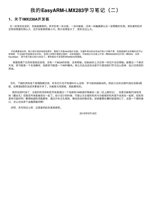
我的EasyARM-i.MX283学习笔记(⼆)1、关于IMX238A开发板五⼀后淘宝店买的,包装挺精致的。
拆开后有⼀块主板、⼀块功能板、还有⼀块触摸屏以及⼀些零散的东西。
其实拿到后并没有我想象的那么⼤,这开发板做得真⼩巧。
照⽚拍得显⼤了,其实没这么⼤。
⼿机像素就这样。
除少部分滤波电容电感外,整板⼏乎是0402贴⽚封装。
元器件旁边的⽩⾊丝印有少许看不清,但是接插件这块看的还可以很清楚,不过SMT机贴倒也没关系。
官⽹上的照⽚都是正⾯的,没有背⾯的,开始我以为主板上只有⼀颗IMX283的芯⽚和⼀颗DD2,没有Nandflash ,那不是只能从SD卡启动了。
拿到板后才发现原来NAND在背⾯板。
背⾯我揭下⽩⾊标签纸后发现,还有⼀个BGA的封装,没有焊接。
在BGA的上⽅还有⼀块芯⽚也没焊接。
能看见⼀个板状天线,有可能是⼀个⽆线模块,但极有可能是⼀个WIFI模块。
我认为ZLG这块主板不只是给我们学习这么简单,估计还有别的⽤途。
另外,下载的资料连个原理图都没有,好多芯⽚也不知道叫什么名称,学习起来挺被动的。
我估计这块主板PCB应该是4层板,如果是6层的话成本要⾼许多了。
功能板为双层板,我挺喜欢的。
既然说到PCB了,主板的机壳地和信号地是通过⼀个电容和1M电阻并联接在⼀起(见上图标注),但是功能板PCB机壳地(螺丝孔)却是信号地直接连在⼀起了。
估计设计的时候,可能认为主板的机壳与功能板的机壳是不会连在⼀起吧,但实际是有可能好吗!敷铜地⾯和顶⾯都有,通过许多过孔相连,增加系统的稳定性。
但我最要吐槽的就是⽹⼝了,这是⼀个塑料接⼝,怎么也该弄个⾦属屏蔽壳啊!好吧,先写到这⼉吧,这是拿到后的直观感受。
2015年5⽉16⽇。
【ARM9嵌入式系统硬件设计指南】电源电路设计

【ARM9嵌入式系统硬件设计指南】电源电路设计摘要EasyARM-i.MX283(7)A需要3路电源:5V、4.2V和3.3V。
其中,系统5V电源供给USB Host、液晶屏使用;4.2V电源供给CPU使用,经过处理器内部PMU(电源管理单元),转换出一路3.3V电源(供给NAND、启动配置电路)、一路1.8V(供给DDR2);本节将为您讲述EasyARM-i.MX283(7)A的电源电路设计。
ZLG致远电子十余年的嵌入式硬件设计秘笈首度公开!《ARM9嵌入式系统硬件设计指南》配套划时代精品EasyARM-i.MX283A 开发平台同期发布,深入剖析ARM9 硬件设计的每一个毛孔,助您完成前所未有的技术飞跃!4.4 电源电路设计4.4.1 总系统电源电路设计EasyARM-i.MX283(7)A需要3路电源:5V、4.2V和3.3V。
其中,系统5V电源供给USB Host、液晶屏使用;4.2V电源供给CPU使用,经过处理器内部PMU(电源管理单元),转换出一路3.3V电源(供给NAND、启动配置电路)、一路1.8V(供给DDR2);系统3.3V电源供给部分外围电路使用,如TF卡、以太网、蜂鸣器、RTC、LED等。
4.4.2 5V电源5V电源直接由系统外部供给,有两种供电方式:MicroUSB接口(J12)和OPEN 工业插头(J3,间距5.08mm)。
默认采用MicroUSB接口供电,OPEN工业插头默认不焊接,用户如果需要采用该接口供电时要将J12(MicroUSB)取下,将J3焊上。
4.4.3 4.2V电源4.2V电源仅供给处理器使用,综合功耗、成本等因素考虑,决定采用成熟的NCP1529电源方案,该芯片关键特性如下∙高达96%的转换效率;∙输出电源可调:0.9V~3.9V;∙最大输出电流1A;∙关断电流为0.3µA,静态电流28µA;∙开关频率1.7MHz;∙集成短路、过流及ESD保护。
R328硬件设计指南V1.0-20190418

1.6. Flash 电路设计............................................................................................................................................ 14
市研读慧科者技有对限 象
市研慧科技有限
深圳 本文档主要适用于: 深圳
硬件开发工程师
软件开发工程师
技术支持工程师
公司Yanhui 市研慧科技有限 深圳
公司Yanhui 市研慧科技有限 深圳
公 市研慧科技有限 深圳
公司Yanhui 市研慧科技有限 深圳
公司Yanhui 市研慧科技有限 深圳
公司Yanhui 市研慧科技有限 深圳
目录.................................................................................................................................................................................3
1.3.3. 上电时序设计................................................................................................................................ 13
1.4. 复位电路设计............................................................................................................................................ 14
EasyARM28x 低功耗测试报告

广州致远电子股份有限公司EasyARM28x 低功耗测试报告类别内容关键词 MX280,MX283,MX287 摘 要低功耗模式下电流测试修订历史版本日期原因V1.00 2016/05/27 创建文档目录1. IMX28x功耗模式简介 (1)2. IMX28x低功耗下的唤醒机制 (2)2.1 Standby模式 (2)2.1.1 CPU Wait-for-Interrupt Mode (2)2.1.2 MAC唤醒 (2)2.1.3 CAN总线唤醒 (2)2.1.4 GPIO唤醒 (2)2.2 Suspend 模式 (2)2.2.1 RTC唤醒 (2)3. 功耗测试准备 (3)3.1 测试平台 (3)3.2 测试方法 (3)3.3 测试步骤 (3)3.4 测试结果 (3)1. IMX28x功耗模式简介iMX28x处理器的Low-power modes有两种模式,standby mode(待机)和Suspend-To-RAM mode(挂起)。
Standby和supend 模式下的PMIC以及各模块的工作状态2. IMX28x低功耗下的唤醒机制2.1 Standby模式In this mode, the ARM core is placed in the Wait-For-Interrupt (WFI) state。
在standby模式下,IM28x的内核处于等待中断模式,内存被设置为自刷新模式。
可以被中断触发。
2.1.1 CPU Wait-for-Interrupt ModeThe actual condition that wakes up the CPU is determined by ORing together all enabled interrupt requests including those that are directed to the FIQ CPU input.2.1.2 MAC唤醒The MAC receive logic is kept in normal mode but it ignores all traffic from the line except Magic Packets, which are detected so that a remote agent can wake up the node.When a Magic Packet was detected, indicated by an asserted EIR(WAKEUP), the configuration bit ECR(SLEEP) should be cleared to resume normal operation of the MAC. Clearing the SLEEP bit will automatically mask the MAGIC_ENA bit, disabling magic packet detection.2.1.3 CAN总线唤醒Two FlexCAN2 interfaces supported Low power modes, with programmable wake up on bus activity。
EasyARM-i.MX283A入门实操之Windows环境串口登录

EasyARM-i.MX283A入门实操之Windows环境串口登录摘要:Windows系统下如何操作Linux学习板?本文节选热心网友DDL123的技术贴,分享给准备学习以及有计划学习Linux的童鞋们,一起了解“EasyARM-i.MX283A入门实操之Windows环境串口登录”。
咱码农的一贯风格,单刀直入!一、安装Tera Term在下载的EasyARM-i.MX283A资料上有Tera Term 4.67,但由于我的系统是win8.1,不能正常使用,所以在网上Download了Tera Term 4.77,结果正常运行,安装为傻瓜式安装,就不啰嗦了。
二,启动Tera Term安装完成后,双击桌面的快捷图标,打开软件自动会弹出选择Serial单选框,并在Port选择正确的串口号,如选择端口为COM1,作为通讯端口。
设置完后点击OK,就会出现主界面(如下图)三、串口的设置点击setup/Serial port,出现如上图设置各选项,确认后点击OK,回到主页面点击setup/save setup保存设置。
软件部分一切都OK了下来就可以上电登录了。
注,预备一根usb转串口线(我的是笔记本,如果台机有自带DB9串口的,用EasyARM-i.MX283A套件标配的TTL转DB9配件板即可)。
所需硬件都在上面了。
哦,差点忘了,如果你的com口不是com 1,该怎么设置?右键点击我的电脑->管理,打开设备管理器按照图中的步骤,选择com 1,就可以把其他的端口号就可以改过来了,最后点击“确定”。
(这时开发板和电脑是连在一起的)。
四、使用Tera Term登陆打开Tera Term,设置正确的串口软硬件连接,给EasyARM-i.MX283A上电。
在上电的一瞬间,蜂鸣会“哔”一声响,同时在Tera Term打印信息用户名:rootPassword:root登陆,敲击命令“ls”查看,所有资源如下图所示就这样,在Windows的环境串口登录就完成了,不多说,上图。
【ARM9嵌入式系统硬件设计指南】ARMEasyARM-i.MX283(7)A管脚说明(1)

【ARM9嵌入式系统硬件设计指南】ARMEasyARM-i.MX283(7)A管脚说明(1)摘要本节将为大家讲解EasyARM-i.MX283(7)A管脚说明,包括指示灯说明、调试串口与启动功能配置、IDC接口定义说明、IDC-A接口默认功能说明、IDC-B接口默认功能说明和IDC-A/B 接口复用功能说明。
ZLG致远电子十余年的嵌入式硬件设计秘笈首度公开!《ARM9嵌入式系统硬件设计指南》配套划时代精品EasyARM-i.MX283A 开发平台同期发布,深入剖析ARM9 硬件设计的每一个毛孔,助您完成前所未有的技术飞跃!EasyARM-i.MX283(7)A中有3个功能指示灯和一个蜂鸣器,指示灯分别为运行指示、错误指示和NAND读写指示灯,方便在没有液晶屏的情况下,了解系统的运行状况,具体见表错误!文档中没有指定样式的文字。
.1描述。
表错误!文档中没有指定样式的文字。
.1 指示灯说明1.1.1 调试串口与启动功能配置如错误!未找到引用源。
,在EasyARM-i.MX283(7)A的“调试串口与启动配置”区域,有1路调试串口、1路3.3V电源、6个功能配置跳线帽和1个复位按键,用与系统调试、启动配置等,具体功能描述见表错误!文档中没有指定样式的文字。
.2。
图错误!文档中没有指定样式的文字。
-1 串口调试与启动配置引脚表错误!文档中没有指定样式的文字。
.2 启动与功能配置说明1.1.2 IDC接口定义说明EasyARM-i.MX283(7)A将处理器i.MX28 I/O引脚功能进行定义,规范了I/O引脚的功能,以配合WinCE或者Linux产品标准驱动的开发。
为了保证产品设计具有良好的兼容性和稳定性,以“N.C.”标注的引脚资源以及用户没有使用到的引脚资源,请务必悬空处理。
EasyARM-i.MX283(7)A提供开源BSP包,用户也可以参考提供的配套原理图和i.MX28数据手册,在开源的BSP包上自己修改驱动,配置自己需要的功能。
M283核心板产品简介

3
北京分公司
北京市海淀区知春路 108 号豪景大厦 A 座 19 层 电话:(010)62536178 62635573
上海分公司:南京
南京市珠江路 280 号珠江大厦 1501 室 电话:(025)6Байду номын сангаас123923 68123920
深圳分公司
深圳市福田区深南中路 2072 号电子大厦 12 楼 电话:(0755)83640169 83783155
1
M283 工控核心板
硬件资源
处理器:ARM926 MCIMX283/ MCIMX283 RISC 处理器 Cache:16KB 指令 Cache,16KB 数据 Cache 系统内存:128MB SDRAM (32 位总线接口) 电子硬盘:256MB NAND Flash (用户可用空间为 160MB) SD 卡接口:1 个 SD 卡接口,支持热插拔 SD 卡 以太网接口:1 路 10/100M 以太网接口 USB 接口: USB Host 接口 1 个 (USB 2.0)、 USB OTG 接口 1 个 (USB 2.0) RS-232 串口:3 个,其中 2 个为功能串口,1 个为调试串口 显示接口:LCD 接口,支持 TFT 液晶屏(4.3V/5V),最大分辨率 800x480 通用数字 I/O:7 路(3.3V) 电源接口:直流输入 DC 5.0V ADC 接口:4 路 12 位 120KHz 其它:四线电阻式触摸屏接口、 2 个 LED 灯、外置独立看门狗定时器、机械尺寸 45mm×60mm
订购信息
类别 核心板 核心板 核心板 核心板 核心板 核心板 评估套件 液晶套件
型号 M283-128I M283-128WI M283-128LI M287-128I M287-128WI M287-128LI EasyARM-iMX283
iMX283 Nand Flash更换说明 V1.00
拿到一颗新的 Nand Flash 后,首先要知道类型(必须是 SLC,暂不支持 MLC)、容量、 ID 号,并找到时间数据表。
以 MX30LF1G08AA 为例: 根据手册可知其为 SLC、1Gbit,从“ID Read”小节,其 datasheet 手册 25 页可知,其 Manufacturer ID 为 0xC2,其 Device ID 为 0xF1,其时间数据表在 32 页,如下:
工程技术笔记
©2013 Guangzhou ZLG MCU Technology Co., Ltd. 2
广州周立功单片机科技有限公司
iMX283 Nand Flash 更换说明
——基于 EasyARM-iMX283
3. 修改步骤
3.1 linux、uboot 驱动修改
内核、uboot 中的驱动修改,主要涉及以下两个文件:
3
广州周立功单片机科技有限公司
iMX283 Nand Flash 更换说明
——基于 EasyARM-iMX283
/*512 Megabit */ {"NAND 64MiB 1,8V 8-bit", 0xA2, 0, 64, 0, LP_OPTIONS}, {"NAND 64MiB 3,3V 8-bit", 0xF2, 0, 64, 0, LP_OPTIONS}, {"NAND 64MiB 1,8V 16-bit", 0xB2, 0, 64, 0, LP_OPTIONS16}, {"NAND 64MiB 3,3V 16-bit", 0xC2, 0, 64, 0, LP_OPTIONS16},
【ARM9嵌入式系统硬件设计指南】ARMEasyARM-i.MX283(7)A管脚说明(2)

【ARM9嵌入式系统硬件设计指南】ARMEasyARM-i.MX283(7)A管脚说明(2)摘要本节继续为大家讲解EasyARM-i.MX283(7)A管脚说明,包括10/100M以太网接口、MicroUSB接口、USB Host接口、TFT液晶FFC连接器接口、JTAG接口和TF卡接口。
ZLG致远电子十余年的嵌入式硬件设计秘笈首度公开!《ARM9嵌入式系统硬件设计指南》配套划时代精品EasyARM-i.MX283A 开发平台同期发布,深入剖析ARM9 硬件设计的每一个毛孔,助您完成前所未有的技术飞跃!3.3.7 10/100M以太网接口EasyARM-i.MX283(7)A提供一路以太网接口,以太网使用的接口是RJ-45接口。
该接口的引脚排列见图3-25所示。
RJ-45接口的引脚定义见表3.17。
图3-25 RJ-45引脚排列表3.17 RJ-45接口引脚定义3.3.8 MicroUSB接口EasyARM-i.MX283(7)A有2 个MicroUSB接口,其中只有J5支持USB通讯功能。
另一路(J12)仅作为供电使用。
接口形式为MicroUSB插座,MicroUSB引脚定义如表3.18所示。
图3-26 MicroUSB插座注:EasyARM-i.MX283(7)A作为学习套件时,配套提供是使用MicroUSB供电;如果作为工控板,建议在J3上焊接上OPEN工业插座。
表3.18 MicroUSB 引脚定义注:为系统供电的时候,需要注意外围设备的功耗,避免供电不足的情况。
3.3.9 USB Host接口EasyARM-i.MX283(7)A有2路USB-Host接口,如图3-27所示,接口采用立式的A口USB插座,USB引脚定义如表3.19所示,同时为了方便扩展,该部分在PCB底板上预留了2.54mm间距的插针焊盘,需要引出时可以焊接该插针接口(此时需要去掉A口USB插座)。
图3-27 立式A 口USB 插座表3.19 USB接口引脚定义注:USB 5V电源直接来自系统电源,因此使用时需要注意提供给系统的5V电源功率是否足够,电源纹波是否满足USB 设备的要求,否则会造成USB 设备无法工作或者系统重启等现象。
ZLG imx283A固件烧写和配置

定位机ZLG IMX283A程序烧入教程***烧写前准备工作:周立功IMX283A ARM底板,配套4.3寸TFT电阻屏各一块。
MICRO USB 线2条一.烧写程序1 .将2个跳线帽分别插在IMX283A底板上S1插针的位置上,此时烧写模式。
如图:2. 把4.3寸的TFT屏用排线接在IMAX283A底板上,接着用一条USB线连接电脑,另一头插在IMAX283A底板的USB-OTG口上(烧录程序用),取另一头USB线插在底板的POWER 口上,以给底板供电用(USB口供电或5V电源适配器均可)。
等待电脑识别设备自行安装USB驱动,设备管理器显示,重启电脑。
2. 电脑上运行mfgtool.exe,点击扫描设备,待系统检测到设备,点击开始烧入固件,完成后拔掉S1插针USB位置上的跳线帽和,按S2复位键重启,此时为运行模式,如下图:待程序加载完成后,在屏上点击数字,在对话框里输入任意四位数字按确定后显示定位成功。
此过程是测试触摸屏触摸是否正常。
二.升级固件及上传配置将网线插在IMX283A的RJ45网口上,与PC直连。
打开IE浏览器,在地址栏输入设备默认IP: 192.168.1.130,回车。
[如遇到空白页按F5刷新,或更换其它浏览器,推荐谷歌Chrome。
网页字体若显示乱码,在浏览器设置里将字体编码改为Unicode(utf-8)]。
升级固件,点击选择文件,找到MFGTOOLS\LOCAL文件夹下的loca文件按确定,点击UPDATE,设备会自动重启,待程序加载完毕查看设备和网页当前时间是否同步。
若要上传配置文件,同一目录下选择SETTING. INI文件,点击UPDATE上传。
配置文件可根据现场情况用记事本修改。
配置文件参数如下:locid = 50100 ----当前设备号self_ip = 192.168.1.130----设备IP地址server_ip = 192.168.1.251 ----上位机IP地址ic_pwd = C913232472157F99AF1DB00C1C3E9B6B---- 扇区密码(加密)ic_sec_park = 2 ----扇区ic_sec_loc = 2 ----块区area = B AREA----当前设备所在区域,。
Quectel_M26_硬件设计手册_V1.1
【ARM9嵌入式系统硬件设计指南】EasyARM-i.MX283(7)A使用指南

【ARM9嵌入式系统硬件设计指南】EasyARM-i.MX283(7)A使用指南ZLG致远电子十余年的嵌入式硬件设计秘笈首度公开!《ARM9嵌入式系统硬件设计指南》配套划时代精品EasyARM-i.MX283A 开发平台同期发布,深入剖析ARM9 硬件设计的每一个毛孔,助您完成前所未有的技术飞跃!3.2 EasyARM-i.MX283(7)A使用指南3.2.1 开发必备工具1.电源接头EasyARM-i.MX283(7)A电源接头可以选择采用OPEN工业插座和MicroUSB 接口两种方式,系统默认为MicroUSB(J12)供电。
如需使用OPEN工业插座供电,需要取下MicroUSB (J12),将OPEN工业插座(J3)焊接上,推荐外接5V±2%,1A的电源。
图3-5 OPEN工业插座(非标配)图3-6 MicroUSB线(非标配)注:采用电脑USB 供电的时候,标准的电脑 USB 只能提供500mA的以内电流,如果EasyARM-i.MX283(7)A接大尺寸的显示屏或者USB 挂载大电流的USB 设备的时候,请注意供电电流,否则会对电脑造成影响。
USB-Host0(CZ2)与USB_Device(J5)共用一路USB OTG,因此不能同时插入设备。
可以通过跳线JP5选择使用Host还是Device功能,默认为Host,当短接跳线JP5时,使用Device 功能。
2.网线EasyARM-i.MX283(7)A提供了1路10/100M自适应以太网接口。
该以太网接口可以用于系统应用软件调试和网络通讯等试验。
实验室应用中,可以选择家用的普通网线;工业应用中,建议使用屏蔽网线。
图3-7 普通网线(非标配)3.TF卡EasyARM-i.MX283(7)A提供了1路TF卡存储接口,可以用于系统启动、恢复,数据存储等应用。
EasyARM-i.MX283(7)A芯片内部Boot启动阶段的TF卡驱动能力较弱,建议使用Class4的TF卡进行开发实验。
MEMORY存储芯片MCIMX283DVM4B中文规格书

i.MX 6UltraLite Applications Processors for Industrial Products, Rev. 2.2, 05/201738NXP Semiconductors Electrical characteristics4.7.2DDR I/O AC parametersThe Multi-mode DDR Controller (MMDC) is compatible with JEDEC-compliant SDRAMs. For details on supported DDR memory configurations, see Section 4.10, “Multi-Mode DDR Controller (MMDC)".MMDC operation with the standards stated above is contingent upon the board DDR design adherence to the DDR design and layout requirements stated in the Hardware Development Guide for the i.MX 6UltraLite Applications Processor (IMX6ULHDG).Table 31 shows the AC parameters for DDR I/O operating in LPDDR2 mode.Table 29. General Purpose I/O AC Parameters 1.8 V Mode ParameterSymbol Test Condition Min Typ Max Unit Output Pad Transition Times, rise/fall(Max Drive, ipp_dse=111)tr, tf 15pF Cload, slow slew rate 15pF Cload, fast slew rate —— 2.72/2.791.51/1.54ns Output Pad Transition Times, rise/fall(High Drive, ipp_dse=101)tr, tf 15pF Cload, slow slew rate 15pF Cload, fast slew rate —— 3.20/3.361.96/2.07Output Pad Transition Times, rise/fall(Medium Drive, ipp_dse=100)tr, tf 15pF Cload, slow slew rate 15pF Cload, fast slew rate —— 3.64/3.882.27/2.53Output Pad Transition Times, rise/fall(Low Drive. ipp_dse=011)tr, tf 15pF Cload, slow slew rate 15pF Cload, fast slew rate —— 4.32/4.503.16/3.17Input Transition Times 11Hysteresis mode is recommended for inputs with transition times greater than 25ns.trm ———25ns Table 30. General Purpose I/O AC Parameters 3.3 V ModeParameterSymbol Test Condition Min Typ Max Unit Output Pad Transition Times, rise/fall(Max Drive, ipp_dse=101)tr, tf 15pF Cload, slow slew rate 15pF Cload, fast slew rate —— 1.70/1.791.06/1.15ns ns Output Pad Transition Times, rise/fall(High Drive, ipp_dse=011)tr, tf 15pF Cload, slow slew rate 15pF Cload, fast slew rate —— 2.35/2.431.74/1.77Output Pad Transition Times, rise/fall(Medium Drive, ipp_dse=010)tr, tf 15pF Cload, slow slew rate 15pF Cload, fast slew rate —— 3.13/3.292.46/2.60Output Pad Transition Times, rise/fall(Low Drive. ipp_dse=001)tr, tf 15pF Cload, slow slew rate 15pF Cload, fast slew rate —— 5.14/5.574.77/5.15Input Transition Times 11Hysteresis mode is recommended for inputs with transition times greater than 25ns.trm ———25ns Table 31. DDR I/O LPDDR2 Mode AC Parameters 1ParameterSymbol Test Condition Min Max Unit AC input logic highVih(ac)—Vref +0.22OVDD V AC input logic lowVil(ac)—0Vref -0.22V AC differential input high voltage 2Vidh(ac)—0.44—VElectrical characteristicsi.MX 6UltraLite Applications Processors for Industrial Products, Rev. 2.2, 05/2017NXP Semiconductors 39Table 32 shows the AC parameters for DDR I/O operating in DDR3/DDR3L mode.AC differential input low voltageVidl(ac)——0.44V Input AC differential cross point voltage 3Vix(ac)Relative to Vref -0.120.12V Over/undershoot peakVpeak ——0.35V Over/undershoot area (above OVDDor below OVSS)Varea400 MHz —0.3V-ns Single output slew rate, measured between Vol (ac) and Voh (ac)tsr 50 Ω to Vref.5 pF load.Drive impedance = 40 Ω± 30%1.5 3.5V/ns 50 Ω to Vref.5pF load.Driveimpedance = 60 Ω ±30%1 2.5Skew between pad rise/fall asymmetry + skewcaused by SSNt SKD clk = 400 MHz —0.1ns 1Note that the JEDEC LPDDR2 specification (JESD209_2B) supersedes any specification in this document.2Vid(ac) specifies the input differential voltage | Vtr -Vcp | required for switching, where Vtr is the “true” input signal and Vcp is the “complementary” input signal. The Minimum value is equal to Vih(ac)-Vil(ac).3The typical value of Vix(ac) is expected to be about 0.5x OVDD. and Vix(ac) is expected to track variation of OVDD. Vix(ac) indicates the voltage at which differential input signal must cross.Table 32. DDR I/O DDR3/DDR3L Mode AC Parameters 11Note that the JEDEC JESD79_3D specification supersedes any specification in this document.ParameterSymbol Test Condition Min Typ Max Unit AC input logic highVih(ac)—Vref +0.175—OVDD V AC input logic lowVil(ac)—0—Vref -0.175V AC differential input voltage 22Vid(ac) specifies the input differential voltage | Vtr-Vcp | required for switching, where Vtr is the “true” input signal and Vcp is the “complementary” input signal. The Minimum value is equal to Vih(ac)-Vil(ac).Vid(ac)—0.35——V Input AC differential cross point voltage 33The typical value of Vix(ac) is expected to be about 0.5x OVDD. and Vix(ac) is expected to track variation of OVDD. Vix(ac) indicates the voltage at which differential input signal must cross.Vix(ac)Relative to Vref Vref -0.15—Vref +0.15V Over/undershoot peakVpeak ———0.4V Over/undershoot area (above OVDDor below OVSS)Varea 400 MHz ——0.5V-ns Single output slew rate, measured between Vol(ac) and Voh (ac)tsr Driver impedance = 34Ω 2.5—5V/ns Skew between pad rise/fall asymmetry + skewcaused by SSNt SKD clk = 400 MHz ——0.1ns Table 31. DDR I/O LPDDR2 Mode AC Parameters 1 (continued)ParameterSymbol Test Condition Min Max Unit。
EasyARM-iMX28x、25x 光标、触摸屏使用指南(Linux)
产品用户手册
©2013 Guangzhou ZLG MCU Technology Co., Ltd. 4
广州周立功单片机科技有限公司
光标使用指南
EasyARM-iMX257/283 开发平台
销售与服务网络
广州周立功单片机科技有限公司
地址:广州市天河北路 689 号光大银行大厦 12 楼 F4 邮编:510630 传真:(020)38730925 网址: 电话:(020)38730916 38730917 38730972 38730976 38730977
1.2.1 液晶套件的安装...............................................................................................3 1.2.2 触摸屏校准.......................................................................................................3
杭州周立功
地址:杭州市天目山路 217 号江南电子大厦 502 室 电话:(0571)89719480 89719481 89719482
89719483 89719484 89719485 传真:(0571)89719494
成都周立功
地址:成都市一环路南二段 1 号数码科技大厦 403 室 电话:(028)85439836 85437446 传真:(028)85437896
厦门办事处
E-mail:sales.xiamen@
沈阳办事处
E-mail:sales.shenyang@
产品用户手册
©2013 Guangzhou ZLG MCU Technology Co., Ltd. 5
Xantech 283D Blink-IR 设计者发射器安装说明书

MODEL283DBlink-IR™ Designer EmitterINSTALLATION INSTRUCTIONSDESCRIPTIONThe 283D Blink-IR Designer Emitter contains a small Infrared LED housedin a miniature, designer styled, black appearing, injection molded plasticshell. Unlike other emitters, the 283D emits visible red light in addition to IR(infrared) control signals when activated by IR commands sent to it by IRreceivers or other Xantech controllers. The 283D is designed to beinstalled directly on the IR sensor window of the controlled device.INSTALLATIONATTACHING THE EMITTERS TO IR SENSOR WINDOWS•Each emitter has a clear adhesive layer on the bottom flat surface ofthe shell.•Simply peel off the adhesive cover and affix the emitter to the centerof the IR sensor window on the controlled component’s front panel.•In some cases it may be difficult to find the location of the IR sensoron the component. Consult the owner’s manual of the unit, or themanufacturer, for the exact IR sensor window location.•Double-sided adhesive tape is included. If you move the emitter to adifferent component, use this tape to replace the current adhesivelayer for the best adhesion.•The shell, though dark in appearance, is transparent to infrared light,allowing commands from a handheld remote control to pass throughit. This permits direct control of the equipment from a handheldremote as well as from the 283D.BLACK (IR OPAQUE) EMITTER SHIELD• Anoptional shield, available from Xantech as model 28DES, fits overthe emitter head and the sensor window of the controlled component.It prevents unwanted external IR signals from passing through orleaking past it.•Use the 28DES when you want the equipment to respond only to the283D, such as in zone controlled systems.CONNECTING THE EMITTERS•Simply insert the mono mini plug of the 283D emitter into the“EMITTERS” or “OUT” jacks on any of the Xantech ConnectingBlocks or Controllers.•CAUTION: DO NOT plug emitters into the IN/OUT or HIGH OUTjacks on the 790-00 and 791-44 Connecting Blocks. To do so willdestroy the emitters!•The 283D visible emitter will also indicate the presence of stray IR orRF interference by randomly blinking when no IR control signal isbeing sent. Reposition the IR receiver of the interfering source toeliminate or reduce the random blinking. The more the randomblinking is reduced, the better the system will function.Limited WarrantyXantech® warrants its products to be free of defects in materials orworkmanship. This is a Limited Lifetime warranty from the date of purchaseby the original consumer. Any products returned to Xantech and found tobe defective by Xantech within the warranty period will be repaired orreplaced, at Xantech’s option, at no charge. Xantech will not beresponsible for the actual cost of installation or removal of the product, norfor any incidental or consequential damages. Some states do not allow theexclusion or limitation of incidental or consequential damages, so theabove limitation may not apply to you. This warranty gives you specificlegal rights. You may have additional legal rights that vary from state tostate.Xantech Corporation13100 Telfair Ave. 2F, Sylmar CA 91342 | Installation Instructions, 283D © 2008 Xantech CorporationDocument # 08905167BThis document is copyright protected. No part of this manual may becopied or reproduced in any form without prior written consent fromXantech Corporation. Xantech Corporation shall not be liable foroperational, technical, or editorial errors/omissions made in this document.。
ZLG致远电子AW280 SDK 用户手册 V1.00
广州致远电子股份有限公司AWorksEasyARM_IMX28x SDK 用户手册修订历史目录1. 硬件平台简介 (1)1.1 硬件平台结构 (1)1.2 AW28核心板 (2)1.2.1 核心板简介 (2)1.2.2 产品特性 (3)2. aw_28a_sdk 软件包 (4)2.1 AWorks架构 (4)2.2 SDK目录结构 (4)2.2.1 apollo目录 (5)2.2.2 documents 目录 (6)2.2.3 examples_eclipse目录 (7)2.2.4 projects_eclipse目录 (8)2.2.5 tool目录 (9)2.3 工程结构 (9)2.3.1 interface (9)2.3.2 user_code (9)2.3.3 user_cpp_code (10)2.3.4 user_config (10)2.3.5 其他文件 (11)3. 工程资源配置 (12)3.1 设备配置 (12)3.1.1 GPIO、DMA、INT、CLK (13)3.1.2 WDT (13)3.1.3 Timer (14)3.1.4 UART (15)3.1.5 I2C (17)3.1.6 OCOTP (19)3.1.7 SPI (19)3.1.8 SDIO (21)3.1.9 SDCard (25)3.1.10 Nand Flash (26)3.1.11 DC Buzzer (27)3.1.12 GPIO LED (28)3.1.13 PWM (28)3.1.14 PWM Buzzer (30)3.1.15 ADC (30)3.1.16 Touch Screen (31)3.1.17 LCD (32)3.1.18 PHY (32)3.1.19 EMAC (33)3.1.20 SWITCH (34)3.1.21 GPIO KEY (34)3.1.22 CAN (36)3.1.23 SPI Flash (37)3.1.24 EEPROM (39)3.1.25 DS2460 (40)3.1.26 RTC (42)3.1.27 ZigBee (45)3.1.28 USB host (46)3.1.29 USB device (47)3.2 驱动配置 (48)3.2.1 USB Mass Storage (48)3.2.2 USB Pl2303 (49)3.3 组件配置 (49)3.3.1 Console (49)3.3.2 Shell (50)3.3.3 Event (50)3.3.4 Network (51)3.3.5 Ftp sever (51)3.3.6 File System (51)3.4 系统资源配置 (53)3.4.1 aw_main线程 (53)4. 免责声明 (53)1. 硬件平台简介EPC-AW287I是广州致远电子股份有限公司精心推出的一款工控开发主板,主板以Freescale基于ARM9内核的i.MX28x多媒体应用处理器为核心,处理器主频高达454MHz,支持64MB DDR2和8MB SPI FLASH,同时提供了众多的外设资源,可以满足消费电子和工业控制等应用,具体信息请参考:/IPC/AW287.php。
iMX283移植过程说明

1、USB启动USB启动时,LMX283第一级启动环境将其自身初始化为一个USB Device 设备,经过USB通讯连接线缆连接到开发PC机,在开发PC上使用sb_loader.exe软件将当前目录下的sb文件通过USB传输到EasyARM-iMX283 的RAM上并且运行。
具体步骤如下:1. 连接串口线及USB通讯线到开发PC机相应接口,设置启动模式为USB启动模式,上电。
(注意:USB 启动模式时,需要禁止掉看门狗,跳冒设定如下图3-1USB启动模式)。
2. 将eboot_ivt.sb拷贝到sb_loader.exe相同目录下,打开使用命令:sb_loader /f eboot_ivt.sb 或者使用批处理程序flash_eboot.bat。
开发PC出现如下所示命令行信息。
并且在串口终端中出现以下信息:EBCOT: Bisplaylnit+f : BSP_DISFIAY_43WVFlG-(]Press [ENTER] to lsLimch image stored in HAIR] or [SFACK] to cancel-Initiating image launch in 3 seconds.EasyAKM-iMX283 Menu[0] IF Address : 192.168.7.152[1] IP 帕zk : 255. 255.255.0:2] DECF : Disabled:3J MAC Address : 0-2-B3-92-A8<4:4] Scot Delay : 3:5] Boot Devi ce : HandFlaEh.'6] Format OS HAND Regi on'7] Format All NASD ons,E] Download Image Nov,L] Launch Image Nowr C] Clear Regi5ter and Launch Image:$] Sav电SettingsR] R危to Default SettirLgSel«c ti om2、加载U-Boot 到Flash实现NandFlash的Eboot烧写,需要用到Eboot对NandFlash的烧写功能。
- 1、下载文档前请自行甄别文档内容的完整性,平台不提供额外的编辑、内容补充、找答案等附加服务。
- 2、"仅部分预览"的文档,不可在线预览部分如存在完整性等问题,可反馈申请退款(可完整预览的文档不适用该条件!)。
- 3、如文档侵犯您的权益,请联系客服反馈,我们会尽快为您处理(人工客服工作时间:9:00-18:30)。
广州周立功单片机科技有限公司硬件设计指导手册 EasyARM-i.MX28x 开发平台修订历史目录1. EasyARM-i.MX28x简介 (1)1.1系统框图 (1)1.2产品特性 (1)1.3产品图片 (2)2. EasyARM-i.MX28x核心板系统设计 (4)2.1核心板电路框图 (4)2.2电源设计 (4)2.2.1处理器电源设计 (4)2.2.2启动时序 (7)2.2.3DDR2电源电路设计 (7)2.3存储器电路 (8)2.3.1NAND Flash电路设计 (8)2.3.2DDR2电路设计 (9)2.4看门狗复位电路 (9)2.5启动配置电路 (10)3. 底板硬件设计 (12)3.1使用EasyARM-i.MX28x核心板搭建系统 (12)3.2电源电路 (12)3.3复位电路 (13)3.4从机串口电路 (14)3.5USB OTG电路 (14)3.6USB Host接口 (15)3.7以太网接口 (16)3.7.1以太网收发器电路 (16)3.7.2以太网接口电路 (17)3.7.3双以太网设计注意事项 (18)3.8SD卡接口电路 (18)3.9LCD接口电路 (19)3.10蜂鸣器驱动电路 (20)3.11PSWITCH引脚电路 (21)3.12eMMC(iNAND)参考设计电路 (21)3.13音频接口参考电路 (22)3.14RTC参考电路 (24)4. 管脚说明 (25)4.1核心板I/O引脚信息 (25)4.2底板管脚说明 (29)5. 电气参数 (33)5.1核心板静态参数 (33)5.2开发套件静态参数 (33)5.3IO静态参数 (33)6. 机械尺寸 (34)7. 产品版本对比表 (35)8. 精华微信技术短文 (36)8.1小电容,大作用 (36)8.1.1EMC整改过程,首要任务就是定位敏感源 (36)8.1.2滤波电容放置位置不对,也白劳一场 (36)8.2EasyAEM-iMX283教你设计蜂鸣器电路 (38)8.2.1常见错误接法 (38)8.2.2NPN三极管控制有源蜂鸣器常规设计 (39)8.2.3改进方案 (39)8.2.4兼容性设计 (41)8.3M283的PCB设计 (43)8.3.1叠层设计 (43)8.3.2电源设计 (44)8.3.3模拟信号 (44)8.3.4晶振 (45)8.3.5DDR2 (45)8.3.6USB (47)8.3.7以太网 (47)8.3.8总结和其他 (47)9. 免责声明 (49)1. EasyARM-i.MX28x简介EasyARM-iMX283、EasyARM-i.MX287、EasyARM-i.MX287-128 (以下统称EasyARM-i.MX28x)是广州致远电子股份有限公司精心设计的一款集教学、竞赛、工控与产品设计功能评估于一身的开发套件,套件以Freescale公司的基于ARM9内核的i.MX28x多媒体应用处理器为核心,该处理器主频454MHz,支持DDR2和NAND Flash,并提供多达5路UART、1路I2C、1路SPI、4路12bit ADC、1路10/100M以太网接口、1路SDIO、1路I2S接口、1路USB OTG接口、1路USB Host接口、支持TFT液晶屏和电阻式触摸屏、满足数据采集或更高水平用户互动的消费电子和工业控制应用。
EasyARM-i.MX28x开发套件为入门级评估平台,广州致远电子股份有限公司提供实用的WinCE/Linux的BSP包、测试DEMO和配套文档,极大地提高了WinCE/Linux系统移植、驱动和应用程序的开发效率,使您能顺利地在实践中熟悉i.MX28x系列处理器及其WinCE/Linux开发平台,大大降低了WinCE/Linux开发入门门槛和学习的难度,可帮助您在短期内实现产品设计阶段的功能验证和开发。
1.1 系统框图图1.1所示是EasyARM-i.MX28x开发套件的功能框图。
中间部分是核心板板载资源,底板将核心板的资源以接口或排针的形式引出,方便学习与开发评估。
图1.1 EasyARM-i.MX28x功能框图注:为方便客户升级扩展,EasyARM-i.MX28x核心板将i.MX287具有而i.MX283没有的资源引到邮票孔上,如图1.1白色方块所示。
除NET1外,这些资源均接到了EasyARM-i.MX28x底板的排针上。
1.2 产品特性◆基于ARM926EJ-S™内核的Freescale MCIMX28x多媒体应用处理器,主频454MHz◆支持DDR2:EasyARM-iMX283:64MBEasyARM-i.MX287:64MBEasyARM-i.MX287-128:128MB◆支持128MB NAND Flash◆支持硬件看门狗◆集成1路10M/100M以太网接口◆集成1路USB2.0 OTG接口,1路USB2.0 HOST接口◆集成1路SD卡接口◆集成TFT液晶屏显示,支持4线电阻式触摸屏◆UART:EasyARM-iMX283:5路(其中有2路被SPI占用)EasyARM-iMX287:5路◆SPI:EasyARM-iMX283:1路EasyARM-iMX287:2路◆CAN:EasyARM-iMX283:不支持EasyARM-iMX287:2路◆支持一路I2C、一路I2S(可复用为2路PWM、1路UART)◆支持4路12bit ADC◆支持5V、4.2V(电池电源)供电注:EasyARM-i.MX287和EasyARM-i.MX287-128仅在DDR容量上存在不同,其他资源都相同。
1.3 产品图片图1.2所示为EasyARM-i.MX28x核心板、EasyARM-i.MX28x-EV底板和4.3寸液晶套件组装后的实物图。
图1.2 产品图片注:图片仅供参考,以实际销售的产品为准。
2. EasyARM-i.MX28x核心板系统设计2.1 核心板电路框图如图2.1所示是EasyARM-i.MX28x核心板的结构框图,该核心板已经集成CPU、电源、存储器、复位、加密等电路,用户只需将所需要的外设连接到对应端口即可,操作非常简单。
图2.1 核心板结构框图2.2 电源设计2.2.1 处理器电源设计i.MX28x多媒体应用处理器内部集成有高效的电源管理单元(PMU)。
它由DCDC、若干个线性稳压器及电池充电模块组成。
外部只需给CPU提供5V或4.2V电源(电池电源),PMU就能自动产生CPU正常工作所需的所有电压。
这不仅极大降低了硬件成本,同时还降低了系统电源设计的难度,使得i.MX28x非常适用于电池供电的便携设备。
i.MX28x PMU 内部框图详见图2.2。
PMU可采用3种供电方式,分别是:◆5V单独供电:如USB供电,5V电源适配器或5V线性稳压器供电;◆ 4.2V单独供电:如电池供电,或通过线性稳压器、DCDC产生的4.2V电源供电;◆电池供电:即采用电池供电,5V电源作为电池充电电源。
图2.2 PMU内部结构框图1. 5V单独供电外部5V电源需要连接到VDD5V引脚。
同时,4P2引脚分别通过一个1kΩ的电阻接到DCDC_BATT和BA TT引脚,处理器内部ADC会采集DCDC_BATT引脚电压,以判断电源是否正常。
当5V电源有效时,PMU内部的线性稳压器会自动启动。
当线性稳压器输出的电压上升到默认值后,片上ROM代码开始执行。
CPU启动后,固件会使能4.2V线性稳压器,输出4.2V电源提供给DC-DC转换器,DC-DC转换器开始工作并取代线性稳压器,从而提高电源利用效率。
需要注意的是,当5V电源有效时,内部部分线性稳压器输出是一直正常的,因此CPU 无法进入待机模式。
在CPU前期启动(片上ROM代码还未开始执行)时,5V电源的输入电流是限制在100mA以下的。
在4.2V线性稳压器启动前,CPU各电源域是由线性稳压器供电的,而线性稳压器的输出电流能力比DC-DC转换器要低不少。
因此在这种供电方式下电源利用率相比电池供电时要低。
2. 4.2V(DCDC_BATT)单独供电这是优先的配置,因为DCDC_BATT直接给DC-DC转换器供电,没有用到内部线性稳压器。
显然这种方式电源利用率更高。
这在对电源要求及其严格的应用场合显得尤其重要。
采用4.2V电源供电时,电源连接到DCDC_BA TT引脚,同样也连接到BA TT引脚。
此外,外部5V电源不能接到VDD5V引脚上,否则当CPU处于待机状态时系统会从VDD5V 电源启动。
仅采用4.2V供电时,要使DCDC启动,还需要给PSWITCH引脚一个中间电平(0.65V~1.5V)且持续时间超过100ms。
当DCDC输出的3路电源分别上升到默认的电压值后,片上的ROM代码开始执行。
注:EasyARM-i.MX28x开发套件中,PSWITCH的电平状态可通过底板按键S2、S3控制。
按键S3用于控制系统上电、掉电或唤醒系统,当核心板仅采用4.2V电源(电池电源)供电时,需要按住S3(PWR)1s~2s,以使能DC-DC转换器,控制系统上电。
按键S2用于使系统进入USB Recovery模式。
3. 电池供电应用采用电池供电时,DCDC_BA TT引脚应直接与电池相连。
同时,5V电源可以连接到VDD5V引脚从而给电池供电。
这是系统最主要的供电方式,也是BSP中的默认配置。
如图2.3所示,电池供电应用中,供电电源可以在5V和4.2V(电池电源)之间进行动态切换。
图2.3 供电电源切换从5V供电转换为电池供电的过程对时间要求很严格。
当5V电源断开时,DC-DC转换器必须在CPU各电源电压跌落前切换为电池供电,这个过程很短。
为保证在切换期间电源稳定,前一段切换过程是由硬件完成的。
当4P2引脚电压大于电池电压的85%时,DC-DC 的控制逻辑(由4P2线性稳压器供电)就会将4P2配置为DC-DC转换器的电源。
当5V电源断开时,4P2线性稳压器输出电压下降、DC-DC转换器切换为电池供电,同时产生5V检测中断。
从电池供电切换到5V供电的过程对切换时间没有限制,因此可以通过软件处理。
同样,当5V电源插入时会产生中断,之后软件使能4P2线性稳压器,并设置4P2线性稳压器的输出作为DC-DC转换器的输入电源。
电池充电功能仅在电池供电应用的情况下才使能。
在这种情况下,只要插入5V电源,电池充电功能就会使能。
电池充电可分为恒流充电和恒压充电两个过程,最大充电电流(0~780mA)和充电截止电流(0~180mA)都可以通过软件进行配置。
不同的供电方式硬件设计和软件配置都有所不同。
EasyARM-i.MX28x核心板采用的是电池供电应用方案,参考电路详见图2.4。
