帧中继配置
帧中继配置
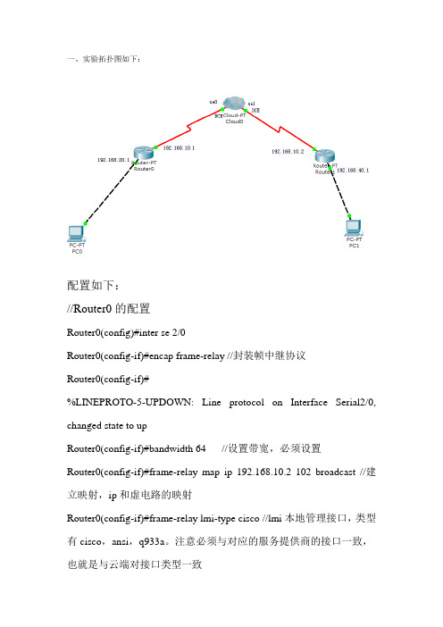
一、实验拓扑图如下:配置如下://Router0的配置Router0(config)#inter se 2/0Router0(config-if)#encap frame-relay //封装帧中继协议Router0(config-if)#%LINEPROTO-5-UPDOWN: Line protocol on Interface Serial2/0, changed state to upRouter0(config-if)#bandwidth 64 //设置带宽,必须设置Router0(config-if)#frame-relay map ip 192.168.10.2 102 broadcast //建立映射,ip和虚电路的映射Router0(config-if)#frame-relay lmi-type cisco //lmi本地管理接口,类型有cisco,ansi,q933a。
注意必须与对应的服务提供商的接口一致,也就是与云端对接口类型一致Router0(config-if)#ip ospf network broadcast //在帧中继上使用ospf 协议的一种方法,开启广播。
Rip不用设置,直接就能使用。
Router0(config-if)#exitRouter0(config)#router ospf 1Router0(config-router)#network 192.168.20.0 0.0.0.255 area 0Router0(config-router)#network 192.168.10.0 0.0.0.255 area 0Router0(config-router)#exit//Router1的配置Router1(config)#interface se 2/0Router1(config-if)#encap frame-relayRouter1(config-if)#%LINEPROTO-5-UPDOWN: Line protocol on Interface Serial2/0, changed state to upRouter1(config-if)#bandwidth 64Router1(config-if)#frame-relay map ip 192.168.10.1 201 broadcast Router1(config-if)#frame-relay lmi-type ansiRouter1(config-if)#%LINEPROTO-5-UPDOWN: Line protocol on Interface Serial2/0, changed state to downRouter1(config-if)#ip ospf p 0 //必须设这权限,让一个路由器成为DRRouter1(config-if)#ip ospf network broadcastRouter1(config-if)#exitRouter1(config)#router ospf 1Router1(config-router)#network 192.168.10.0 0.0.0.255 area 0 Router1(config-router)#network 192.168.40.0 0.0.0.255 area 0 Router1(config-router)#exit//云端的配置选择se0口;DLCI编号:输入102,Name :输入1->2,点击添加Se1类似。
帧中继概念 帧中继配置命令有哪些
帧中继概念帧中继配置命令有哪些1.帧中继概念1、帧中继(FRAME RELAY)是在用户--网络接口之间提供用户信息流的双向传送,并保持顺序不变的一种承载业务,它是以帧为单位,在网络上传输,并将流量控制、纠错等功能,全部交由智能终端设备处理的一种新型高速网络接口技术。
2、帧中继是综合业务数字网标准化过程中产生的一种重要技术,它是在数字光纤传输线路逐渐代替原有的模拟线路,用户终端日益智能化的情况下,由X25分组交换技术发展起来的一种传输技术。
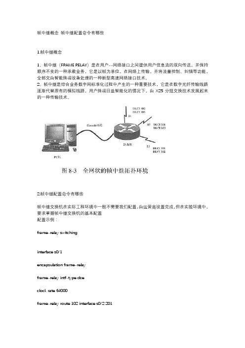
2.帧中继配置命令有哪些帧中继交换机在实际工程环境中一般不需要我们配置,由运营商设置完成,但在实验环境中,要求掌握帧中继交换机的基本配置配置示例:frame-relay switchinginterface s0/1encapsulation frame-relayframe-relay intf-type dceclock rate 64000frame-relay route 102 interface s0/2 201// 定义PVC,该条命令是,s0/1口的DLCI 102,绑定到s0/2口的201 DLCI号frame-relay route 103 interface s0/3 301no shutdown主接口运行帧中继(Invers-arp)FRswitch(帧中继交换机)的配置:frame-relay switchinginterface s0/1 // 连接到R1的接口encapsulation frame-relayframe-relay intf-type dceclock rate 64000frame-relay route 102 interface s0/2 201// 定义PVC,该条命令是,s0/1口的DLCI 102,绑定到s0/2口的201 DLCI号no shutdowninterface s0/2 // 连接到R2的接口encapsulation frame-relayframe-relay intf-type dceclock rate 64000frame-relay route 201 interface s0/1 102no shutdownR1的配置如下:interface serial 0/0ip address 192.168.12.1 255.255.255.252encapsulation frame-relay// 接口封装FR,通过invers-arp发现DLCI,并建立对端IP到本地DLCI的映射(帧中继映射表)no shutdownR2的配置如下:interface serial 0/0ip address 192.168.12.2 255.255.255.252encapsulation frame-relayno shutdown在FRswitch上查看PVI(验证配置):FRswitch#show frame-relay routeInput Intf Input Dlci Output Intf Output Dlci StatusSerial0/1 102 Serial0/2 201 activeSerial0/2 201 Serial0/1 102 active在R1上查看帧中继映射R1#show frame-relay mapSerial0/0 (up): ip 192.168.12.2 dlci 102(0x66,0x1860), dynamic,broadcast,, status defined, activeR1#ping 192.168.12.2Type escape sequence to abort.Sending 5, 100-byte ICMP Echos to 192.168.12.2, timeout is 2 seconds:环境2 主接口运行帧中继(静态映射)FRswitch的配置同上,这里不再赘述上述案例是终端路由器采用动态invers-arp获取帧中继相关映射信息,本例采用静态建立映射的方式进行配置。
帧中继(frame-relay)简介及配置详解

帧中继(Frame-Relay)采用分组交换的方式使用虚电路进行连接提供面向对象的服务帧中继的交换设备在用户路由器间建立虚电路,提供基于分组的二层通道。
相关术语虚电路(virtual circuit,VC)1、通过帧中继网络实现的逻辑连接叫虚电路2、利用虚电路,帧中继允许多个用户共享带宽而无需使用多条专用物理网络,虚电路以DLCI标识DLCI(date link connect identity)数据链路连接标识1、通常由帧中继服务提供商分配2、帧中继DLCI仅具有本地意义(本地标识)3、DLCI 0 ~ 15和1008 ~ 1023留作特殊用途,服务提供商分配的DLCI 的范围通常为16 ~ 1007LMI(本地管理接口)1、是一种信令标准,用于管理链路连接和keeplive机制2、终端路由器(DTE)和帧中继交换机(DCE)之间的帧中继设备每10秒(或大概)轮询一次网络。
3、Cisco路由器支持一下三种LMI:Cisco、Ansi、Q933A帧中继的拓扑:星型结构、全互联、部分互联帧中继的地址映射帧中继提供的是基于分组交换的二层通道1、帧中继的映射不是IP与mac的映射,而是IP与DLCI的映射,DLCI 从运营商处获取,映射关系为远端IP地址到本地DLCI之间的关系。
(DLCI仅具有本地意义)2、可以通过手动配置或 inverse-arp自动发现。
帧中继(用路由器模拟)配置对于帧中继交换机:(三个接口都要配置)frame-relay switching 将路由器模拟成帧中继交换机int s0/1 进入serial 0/1接口no ip address 帧中继交换机不需要IP地址encapsulation frame-relay 设置接口的封装模式为frame-relayno shutdown 开启接口frame-relay intf-type dce 设置接口类型为DCEclock rate 64000 设置始终频率为64000frame-relay route 102 int s0/2 201 搭建虚电路,对于s0/1来说,来源的DLCI标识为102,发出的接口为serial0/2,目的DLCI为201frame-relay route 103 int s0/3 301 搭建虚电路,对于s0/1来说,来源的DLCI标识为103,发出的接口为serial0/3,目的DLCI为301int s0/2no ip addressencapsulation frame-relayno shutdown 开启接口frame-relay intf-type dce 设置接口类型为DCEclock rate 64000 设置始终频率为64000frame-relay route 201 int s0/1 102 对于serial0/2来说,数据来源的DLCI为201,发出接口为serial0/1,目的DLCI为102int s0/3no ip addressencapsulation frame-relayno shutdown 开启接口frame-relay intf-type dce 设置接口类型为DCEclock rate 64000 设置始终频率为64000frame-relay route 301 int s0/1 103 对于serial0/3来说,数据来源的DLCI为301,发出接口为serial0/1,目的DLCI为103R1的配置:(center)int s0/0ip address 10.1.123.1 255.255.255.0encapsulation frame-relayno shutdownno frame-relay inverse-arp 关闭inverse-arpframe-relay map ip 10.1.123.2 102 broadcast 手动配置帧中继映射,对端IP为10.1.123.2,映射的虚电路的本地DLCI为102frame-relay map ip 10.1.123.3 103 broadcast 手动配置帧中继映射,对端IP为10.1.123.3,映射的虚电路的本地DLCI为103R2的配置:int s0/0ip address 10.1.123.2 255.255.255.0encapsulation frame-relayno shutdownno frame-relay inverse-arp 关闭inverse-arpframe-relay map ip 10.1.123.1 201 broadcast 手动配置帧中继映射,对端IP为10.1.123.2,映射的虚电路的本地DLCI为201R3的配置:int s0/0ip address 10.1.123.3 255.255.255.0encapsulation frame-relayno shutdownno frame-relay inverse-arp 关闭inverse-arpframe-relay map ip 10.1.123.1 301 broadcast 手动配置帧中继映射,对端IP为10.1.123.3,映射的虚电路的本地DLCI为301在帧中继上运行EIGRP默认情况下inverse-arp为开启状态,且支持广播若手动配置则必须加上broadcast关键字段。
第七章 配置帧中继
第七章配置帧中继一、帧中继技术(Frame Relay)帧中继是一种高性能的WAN协议,它运行在OSI参考模型的物理层和数据链路层。
它是一种数据包交换技术,是X.25的简化版本。
它省略了X.25的一些强健功能,如提供窗口技术和数据重发技术,而是依靠高层协议提供纠错功能,这是因为帧中继工作在更好的WAN设备上,这些设备较之X.25的WAN设备具有更可靠的连接服务和更高的可靠性,它严格地对应于OSI参考模型的最低二层(即是第二层协议),而X.25还提供第三层的服务,所以,帧中继比X.25具有更高的性能和更有效的传输效率。
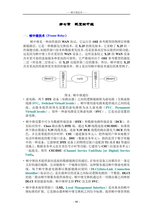
图1是应用帧中继技术通信的典型例子。
图1、帧中继通信• 虚电路:两个DTE设备(如路由器)之间的逻辑链路称为虚电路(交换虚拟线路SVC,Switched VirtualCircuits),帧中继用虚电路来提供端点之间的连接。
由服务提供商预先设置的虚电路称为永久虚电路(PVC,Permanent VirtualCircuits);别外一种虚电路是交换虚电路(SVC),它是动态设置的虚电路。
• 帧中继设置中可分为数据终端设备(DTE)和数据电路终端设备(DCE),在实际应用中,Cisco路由器为DTE端,通过V.35线缆连接CSU/DSU,如果将两个路由器通过V.35线缆直连,连接V.35 DCE线缆的路由器充当DCE的角色,并且需要提供同步时钟。
CSU(通道服务单元):把终端用户和本地数字电话环路相连的数字接口设备。
DSU(数据业务单元):指的是用于数字传输中的一种设备,它能够把DTE设备上的物理层接口适配到T1或者E1等通信设施上。
数据业务单元也负责信号计时等功能,它通常与CSU(信道业务单元)一起提及,称作CSU/DSU (Channel Service Unit/Data [or Digital] Service Unit)。
• 帧中继技术提供面向连接的数据链路层的通信,在每对设备之间都存在一条定义好的通信链路,且该链路有一个链路识别码。
实验3 帧中继配置
帧中继出现背景:数据通信设备(如路由器)以专线方式连接,带来了许多缺点。
首先专线方式采用固定的带宽和接口。
当用户需要改变带宽需求或需扩容时,都不是很方便。
其次是专线连接网络的造价昂贵,用户的租用费也很高。
另外专线方式若将用户两两连接,用户数量为n,则需要n(n-1)/2条电路,不利于网络资源的管理和运用。
帧中继作用:帧中继主要应用在广域网中,支持多种数据型业务。
主要解决以下问题:帧中继在初期运用时非常容易在原有的X.25的接口上进行软件升级来实现。
由于帧中继是基于X.25进行简化的快速分组交换技术,所以在许多使用帧中继的终端应用中,不需要对原有的X.25设备进行硬件上的改造,只需要对其软件进行升级就可以提供帧中继业务。
帧中继的灵活计费方式非常适用于突发性的数据通信。
目前国际上许多运营公司采用承诺信息速率(CIR)计费,CIR用户的通信费用降低。
帧中继技术可以动态分配网络资源。
对于电信运营者来说,可以让用户使用过剩的带宽,而且用户可以共享网络资源,而不需要重新投资。
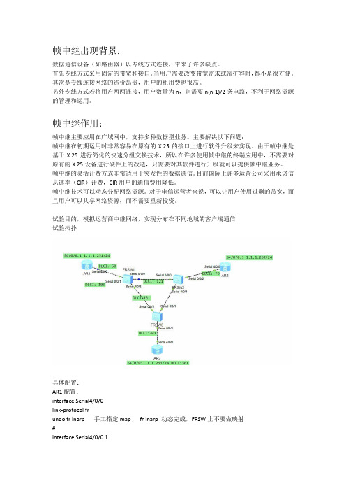
试验目的,模拟运营商中继网络,实现分布在不同地域的客户端通信试验拓扑具体配置:AR1配置:interface Serial4/0/0link-protocol frundo fr inarp 手工指定map , fr inarp 动态完成,FRSW上不要做映射#interface Serial4/0/0.1fr dlci 50fr dlci 103fr map ip 1.1.1.252 50 broadcastfr map ip 1.1.1.253 103 //不配置成broadcast也没有影响ip address 1.1.1.251 255.255.255.0interface LoopBack0ip address 11.1.1.1 255.255.255.255ospf 1peer 1.1.1.253 //帧中继默认是NBMA网络,必须指定邻居area 0.0.0.0network 1.1.1.0 0.0.0.255network 11.1.1.1 0.0.0.0AR3配置:interface Serial4/0/0link-protocol frfr dlci 301fr map ip 1.1.1.251 301 broadcastip address 1.1.1.253 255.255.255.0interface LoopBack0ip address 33.3.3.3 255.255.255.255#ospf 1 router-id 3.3.3.3peer 1.1.1.251area 0.0.0.0network 1.1.1.0 0.0.0.255network 33.3.3.3 0.0.0.0帧中继交换机配置:。
帧中继的基本配置(Basic FrameRealy)
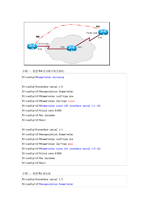
思考:如果在步骤七发现无法PING通R2,可能是因为。
R2的反向ARP的映射尚没有创建成功。
所以我们手工的配置反向是ARP手工静态映射的配置思考:在R1上PING上自己的接口IP。
是否可以PING通?为什么?如果解决?回复 #2 stanley.wy 的帖子谢谢lz ,今天学习Basic FrameRealy步骤一:配置R4的为帧中继交换机。
R4(config)#frame-relay switchingR4(config)#interface serial 1/0R4(config-if)#encapsulation frame-relayR4(config-if)#frame-relay intf-type dceR4(config-if)#frame-relay lmi-type ciscoR4(config-if)#frame-relay route 100 interface serial 1/1 101R4(config-if)#clock rate 64000R4(config-if)#no shutdownR4(config-if)#exitR4(config)#interface serial 1/1R4(config-if)#encapsulation frame-relayR4(config-if)#frame-relay intf-type dceR4(config-if)#frame-relay lmi-type ansiR4(config-if)#frame-relay route 101 interface serial 1/0 101 《--改:serial 1/0 100R4(config-if)#clock rate 64000R4(config-if)#no shutdownR4(config-if)#exit------------------在R1上PING上自己的接口IP。
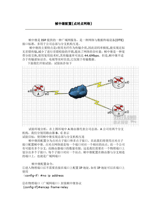
帧中继配置(点到点)
帧中继是ISP提供的一种广域网服务,是一种网络与数据终端设备(DTE)接口标准,多用于公司总部与分支机构互连。
帧中继的主要特点是:使用光纤作为传输介质,因此误码率极低,能实现近似无差错传输,减少了进行差错校验的开销,提高了网络的吞吐量;帧中继是一种宽带分组交换,使用复用技术时,其传输速率可高达44.6Mbps。
但是,帧中继不适合于传输诸如话音、电视等实时信息,它仅限于传输数据。
下面我们开始试验,试验拓扑如下试验环境分析:在上图环境中A路由器代表公司总部,A公司有两个分支机构,我们分别用路由器B、C表示试验目标:使用帧中继实现总部与分支机构互连帧中继的配置分为点对点子接口和多点子接口,在此我们将使用点对点子接口配置帧中继。
点对点网络就是每一个端口对应一个相应的站点,而一个公司有可能有多个分支,而路由器端口的数量有限,这是我们需要在一个物理端口上划分出多个子接口,每个子接口对应一个站点。
帧中继配置在路由器与分支相连的端口上,也就是广域网端口帧中继配置命令:①进入物理端口后不需要直接在端口上配置IP地址,如有IP地址可以在端口上使用(config-if)#no ip address②在物理端口(广域网端口)封装帧中继协议(config-if)#encap frame-relay③激活物理端口(config-if)#no shutdown④在物理端口上建立子接口,并指定接口类型(config-if)#interface 子接口point-to-point⑤给子接口配置IP地址和子网掩码(config-subif)#ip address IP地址子网掩码⑥给子接口配置DLCI值(config-subif)#frame-relay interface-dlci DLCI值⑦给子接口配置端口速率(config-sibif)#bandwidth 带宽DLCI值IP地址规划A:e0---192.168.10.1 B:e0---192.168.20.1 C:e0---192.168.30.1 s0.1--202.110.100.1 s0---202.110.100.2 s0---202.110.10 1.2s0.2--202.110.101.1一、配置A路由器A(config)#interface e0 进入局域网端口A(config-if)#ip address 192.168.10.1 255.255.255.0配置局域网I P和掩码A(config-if)#no shutdown激活局域网端口A(config-if)# interface s0 进入广域网端口A(config-if)#no ip address 删除广域网端口的IPA(config-if)#no shutdown 激活广域网A(config-if)#encap frame-relay封装帧中继协议A(config-if)#interface s0.1 point-to-point 在物理端口上建立子接口S0.1,指定端口类型A(config-subif)#ip address 202.110.100.1 255.255.255.0给子接口配置IP和掩码A(config-subif)#frame-relay interface-dlci 102 给S0.1子接口封装DLCIA(config-subif)#bandwidth 64给S0.1子接口配置A(config-subif)#interface s0.2 point-to-point 建立子接口S0.2,并指定子接口类型A(config-subif)#ip address 202.110.101.1 255.255.255.0 给子接口S0.2配置IP和掩码A(config-subif)#frame-relay interface-dlci 103给S0.2子接口封装DLCIA(config-subif)#bandwidth 64 给S0.2子接口配置端口速率A(config-subif)#exit 退出子接口A(config)#router eigrp 100 配置路由,协议为EIGRPA(config-router)#net 192.168.10.0A(config-router)#net 202.110.100.0A(config-router)#net 202.110.101.0二、配置B路由器B路由器上有两个端口,一个是局域网端口E0,一个是广域网端口S0,S0为连接A路由器的S0.1端口,不需要配置子接口,只需要配置IP地址然后封装帧中继协议即可B(config)#int e0B(config-if)#ip address 192.168.20.1 255.255.255.0B(config-if)#no shutdownB(config-if)#int s0B(config-if)#ip address 202.110.100.2 255.255.255.0B(config-if)#encap frame-relayB(config-if)#frame-relay interface-dlci 201B(config-if)#bandwidth 64B(config-if)#no shutB(config-if)#exitB(config)#router eigrp 100B(config-router)#net 192.168.20.0B(config-router)#net 202.110.100.0三、配置路由器CC路由器有两个端口,E0为局域网端口。
实验报告——实验七:帧中继配置实验
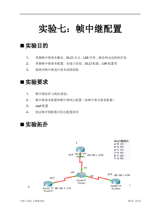
实验七:帧中继配置⏹实验目的1、掌握帧中继基本概念、DLCI含义、LMI作用、静态和动态映射区别2、掌握帧中继基本配置:如接口封装、DLCI配置、LMI配置等3、能够对帧中继进行基本故障排除⏹实验要求1、帧中继拓扑与地址规划;2、帧中继基本配置和帧中继网云配置(如帧中继交换表配置)3、ospf配置4、验证帧中继配置并给出配置清单⏹实验拓扑⏹实验设备(环境、软件)路由器3个,网云一个,串口线3条。
⏹实验设计到的基本概念和理论帧中继用虚电路为面向连接的服务建立连接。
DLCI的含义是数据链路连接标识,在源和目的设备之间标识逻辑电路的一个数值。
LMI的含义是本地管理接口,是客户前端设备和帧中继交换机之间的信令标准,负责管理设备之间的连接、维护设备之间的连接状态。
⏹实验过程和主要步骤1、地址规划情况2、单个路由器的基本配置清单(1)路由器Router0配置Router>enableRouter#config tEnter configuration commands, one per line. End with CNTL/Z.Router(config)#interface s2/0Router(config-if)#no ip addressRouter(config-if)#encapsulation frame-relayRouter(config-if)#interface s2/0.1 multipointRouter(config-subif)#ip address 192.168.1.1 255.255.255.0Router(config-subif)#bandwidth 64Router(config-subif)#frame-relay map ip 192.168.1.2 102 broadcastRouter(config-subif)#frame-relay map ip 192.168.1.3 103 broadcastRouter(config-subif)#exitRouter(config)#interface s2/0Router(config-if)#no shut%LINK-5-CHANGED: Interface Serial2/0, changed state to up%LINK-5-CHANGED: Interface Serial2/0.1, changed state to upRouter(config-if)#%LINEPROTO-5-UPDOWN: Line protocol on Interface Serial2/0, changed state to up %LINEPROTO-5-UPDOWN: Line protocol on Interface Serial2/0.1, changed state to up (2)路由器Router1配置Router>enableRouter#config tEnter configuration commands, one per line. End with CNTL/Z.Router(config)#interface s2/0Router(config-if)#no ip addressRouter(config-if)#encapsulation frame-relayRouter(config-if)#interface s2/0.1 multipointRouter(config-subif)#ip address 192.168.1.2 255.255.255.0Router(config-subif)#bandwidth 64Router(config-subif)#frame-relay map ip 192.168.1.1 201 broadcastRouter(config-subif)#frame-relay map ip 192.168.1.3 203 broadcastRouter(config-subif)#exitRouter(config)#interface s2/0Router(config-if)#no shut%LINK-5-CHANGED: Interface Serial2/0, changed state to up%LINK-5-CHANGED: Interface Serial2/0.1, changed state to upRouter(config-if)#%LINEPROTO-5-UPDOWN: Line protocol on Interface Serial2/0, changed state to up %LINEPROTO-5-UPDOWN: Line protocol on Interface Serial2/0.1, changed state to up(3)路由器Router2配置Router>enableRouter#config tEnter configuration commands, one per line. End with CNTL/Z.Router(config)#interface s2/0Router(config-if)#no ip addressRouter(config-if)#encapsulation frame-relayRouter(config-if)#interface s2/0.1 multipointRouter(config-subif)#ip address 192.168.1.3 255.255.255.0Router(config-subif)#bandwidth 64Router(config-subif)#frame-relay map ip 192.168.1.1 301 broadcastRouter(config-subif)#frame-relay map ip 192.168.1.2 302 broadcastRouter(config-subif)#exitRouter(config)#interface s2/0Router(config-if)#no shut%LINK-5-CHANGED: Interface Serial2/0, changed state to up%LINK-5-CHANGED: Interface Serial2/0.1, changed state to upRouter(config-if)#%LINEPROTO-5-UPDOWN: Line protocol on Interface Serial2/0, changed state to up %LINEPROTO-5-UPDOWN: Line protocol on Interface Serial2/0.1, changed state to up3、网云交换表配置(1)Se0端口的配置:(2)Se1端口的配置(3)Se2端口的配置(4)将其进行连接:4、验证三个路由器通信情况(1)Router0到Router1和Router2(2)Router1到Router0和Router2(3)Router2到Router0和Router1心得体会通过这次的实验我懂得了什么是帧中继以及其作用,知道了DLCI和LMI的含义及其重要性,同时也明白了如何配置帧中继。
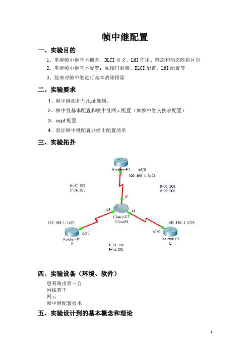
帧中继配置
B(config)#router ospf 1
B(config-router)#network 192.168.1.20.0.0.255 area 0
路由器C:
C(config)#router ospf 1
C(config-router)#network 192.168.1.00.0.0.255 area 0
B(config-if)#ip address 192.168.1.2 255.255.255.0
B(config-if)#no shutdown
路由器C:
Router(config)#hostname C
C(config)#interface Serial2/0
C(config-if)#ip address 192.168.1.3 255.255.255.0
A(config)#interface Serial2/0
A(config-if)#ip address 192.168.1.1 255.255.255.0
A(config-if)#no shutdown
路由器B:
Router(config)#hostname B
B(config)#interface Serial2/0
三、实验拓扑
四、实验设备(环境、软件)
思科路由器三台
网线若干
网云
帧中继配置技术
五、实验设计到的基本概念和理论
帧中继:
帧中继技术是在开放系统互连(OSI)网络模型的第二层(链路层)上以帧的形式用简化的方法传送和交换数据单元的一种数字交换技术。
帧中继技术是在分组技术充分发展,数字与光纤传输线路逐渐替代已有的模拟线路,用户终端日益智能化的条件下诞生并发展起来的。
帧中继的基本配置
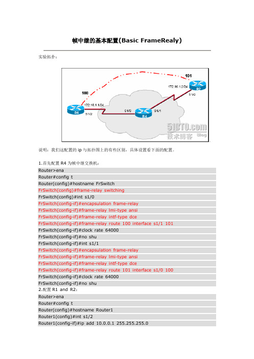
实验拓扑:说明:我们这配置的ip与拓扑图上的有些区别,具体设置看下面的配置。
1.首先配置R4为帧中继交换机:Router>enaRouter#config tRouter(config)#hostname FrSwitchFrSwitch(config)#frame-relay switchingFrSwitch(config)#int s1/0FrSwitch(config-if)#encapsulation fram e-relayFrSwitch(config-if)#frame-relay lmi-type ansiFrSwitch(config-if)#frame-relay intf-type dceFrSwitch(config-if)#frame-relay route 100 interface s1/1 101 FrSwitch(config-if)#clock rate 64000FrSwitch(config-if)#no shuFrSwitch(config-if)#int s1/1FrSwitch(config-if)#encapsulation fram e-relayFrSwitch(config-if)#frame-relay lmi-type ansiFrSwitch(config-if)#frame-relay intf-type dceFrSwitch(config-if)#frame-relay route 101 interface s1/0 100 FrSwitch(config-if)#clock rate 64000FrSwitch(config-if)#no shu2.配置R1 and R2:Router>enaRouter#config tRouter(config)#hostname Router1Router1(config)#int s1/2Router1(config-if)#ip add 10.0.0.1 255.255.255.0Router1(config-if)#enca fram e-relayRouter1(config-if)#frame-relay lmi-type ansiRouter1(config-if)#no shuRouter>enaRouter#config tRouter(config)#hostname Router2Router2(config)#interface s1/2Router2(config-if)#encapsulation frame-relayRouter2(config-if)#ip add 10.0.0.2 255.255.255.0Router2(config-if)#frame-relay lmi-type ansiRouter2(config-if)#no shu3.验证配置:Router1#show fram e-relay m apSerial1/2 (up): ip 10.0.0.2 dlci 100(0x64,0x1840), dynamic,broadcast,, status defined, activeRouter2#show fram e-relay m apSerial1/2 (up): ip 10.0.0.1 dlci 101(0x65,0x1850), dynamic,broadcast,, status defined, activeRouter1#show fram e-relay pvcPVC Statistics for interface Serial1/2 (Fram e Relay DTE)Active Inactive Deleted StaticLocal 1 0 0 0Switched 0 0 0 0Unused 0 0 0 0DLCI =100, DLCI USAGE =LOCAL, PVC STATUS =ACTIVE, INTERFACE =Se rial1/2input pkts 6 output pkts 7 in bytes 554out bytes 588 dropped pkts 0 in FECN pkts 0in BECN pkts 0 out FECN pkts 0 out BECN pkts 0in DE pkts 0 out DE pkts 0out bcast pkts 2 out bcast bytes 685 minute input rate 0 bits/sec, 0 packets/sec5 minute output rate 0 bits/sec, 0 packets/secpvc create tim e 00:13:00, last tim e pvc status changed 00:12:20Router2#show fram e-relay pvcPVC Statistics for interface Serial1/2 (Fram e Relay DTE)Active Inactive Deleted StaticLocal 1 0 0 0Switched 0 0 0 0Unused 0 0 0 0DLCI =101, DLCI USAGE =LOCAL, PVC STATUS =ACTIVE, INTERFACE =Se rial1/2input pkts 6 output pkts 6 in bytes 554out bytes 554 dropped pkts 0 in FECN pkts 0in BECN pkts 0 out FECN pkts 0 out BECN pkts 0in DE pkts 0 out DE pkts 0out bcast pkts 1 out bcast bytes 345 minute input rate 0 bits/sec, 0 packets/sec5 minute output rate 0 bits/sec, 0 packets/secpvc create tim e 00:11:24, last tim e pvc status changed 00:11:14在R1上ping R2:Router#ping 10.0.0.2Type escape sequence to abort.Sending 5, 100-byte ICMP Echos to 10.0.0.2, tim eout is 2 seconds:!!!!!Success rate is 100 percent (5/5), round-trip min/avg/max =120/140/168 ms OK,成功!如果发现ping不通的话,可以使用命令show fram map查看,看是否有R2的反向ARP映射,如果没有的话我们可以手工添加:Router2#show fram e-relay m apSerial1/2 (up): ip 10.0.0.1 dlci 101(0x65,0x1850), static,broadcast,CISCO, status defined, active这样就可以相互通信了。
帧中继基本配置
帧中继基本配置原理:帧中继(Frame Relay)是一种面向连接的数据链路层技术,主要用于公共或者专用网以上的局域网互联的以及广域网连接。
帧中继网络的相关术语如下:DTE(data terminal equipment,数据终端设备):通常指用户侧的主机或者终端等DCE(data circuit-terminating equipment,数据电路终结设备):为用户设备提供接入设备,属于网络设备,如帧中继交换机DLCI(data link connection identifier,数据链路连接标识):虚电路接口的的标识。
帧中继能够在单一物理传输线路上提供多条虚电路,虚电路便是通过DLCI来区分。
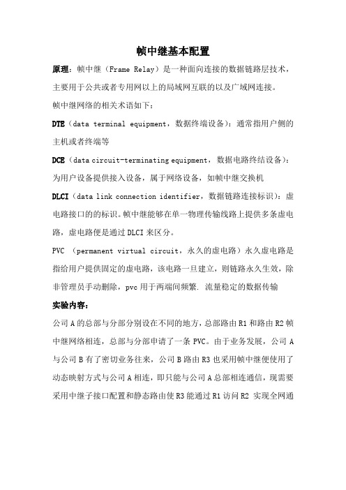
PVC (permanent virtual circuit,永久的虚电路)永久虚电路是指给用户提供固定的虚电路,该电路一旦建立,则链路永久生效,除非管理员手动删除,pvc用于两端间频繁. 流量稳定的数据传输实验内容:公司A的总部与分部分别设在不同的地方,总部路由R1和路由R2帧中继网络相连,总部与分部申请了一条PVC。
由于业务发展,公司A 与公司B有了密切业务往来,公司B路由R3也采用帧中继便使用了动态映射方式与公司A相连,即只能与公司A总部相连通信,现需要采用中继子接口配置和静态路由使R3能通过R1访问R2 实现全网通(1 在帧中继交换机上建立俩条PVC,PVC在S0/0/0接口分配DLCI 为102,在S0/0/1,接口分配DLCI 为201,俩者同属一条PVC(R1和R2一条,R1和R3一条)2.静态与动态映射的配置公司A总部使用动态映射,在R1接口s2/0/0接口配置链路协议为FR,FR inarp命令允许帧中继逆向地址解析功能自动生成地址映射表。
【R2】int s2/0/0【R2-serial2/0/0】link-protocol fr【R2-serial2/0/0】undo frinarp 闭逆向解析功能【R2-serial2/0/0】fr map ip 10.1.1.1 201 手工配置R1的IP 地址与DLCI的静态映射【R2-serial2/0/0】fr map IP 11.1.1.1 201 broadcast (默认下帧中继不支持广播或者组播的转发,所以需在静态映射后面添加broadcast<R1>使用display fr PVC-info 查看PVC建立情况Ping 11.1.1.2 此时R1与R2之间正常通信3.子接口配置和静态路由【R3】int s2/0/0【R3-serial2/0/0】link-protocol fr【R1】int s2/0/0.1【R1-serial2/0/0.1】IP add 22.1.1.1 24【R1-serial2/0/0.1】frdlci 103 (默认情况下帧中继交换机分配的DLCI都关联到用户设备的物理接口上,而子接口的关联的DLCI需要手动指定【R3】IP route-static 11.1.1.2 32 22.1.1.1【R2】IP route-static 22.1.1.3 32 11.1.1.1使用tracert命令查看走的路径。
帧中继
帧中继PVC:虚电路DLCI: data-link connection identifier常用命令:sh frame-relay PVCsh frame-relay route 在帧中继交换机上使用sh frame-relay map 在客户路由器上使用下面通过一个实验来详细的分析帧中继的原理与应用方法。
这个实验分为两个部分。
一.帧中继的基本配置二.在帧中继网络环境下运行各种路由协议。
一.帧中继的基本配置。
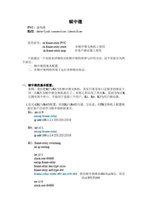
如图,我们把R2与R3当作帧中继交换机,其实只要是串口足够多的情况下用一台R作为帧中继交换机就行了,本例之所以用了两台R,是因为每台R 只拥有两个串口,不能用于连接三个用户。
R1,R4,R5为用户路由器。
1.先完成R1与R4的配置,实现R1与R4的互通。
方法是,在FR交换机上配置映射让客户自动学习帧中继映射条目。
R1:int s1/0encap frame-relayip add 100.1.1.1 255.255.255.0R4:int s1/1encap frame-relayip add 100.1.1.4 255.255.255.0R2:frame-relay switchingno ip routingint s1/1clock rate 64000encap frame-relayframe-relay lmi-type ciscoframe-relay intf-type dceframe-relay route 401 int s1/0 104 指出帧中继路由401从s1/0出,而且从s1/0收到104int s1/0clock rate 64000frame-relay lmi-type ciscoframe-relay intf-type dceframe-relay route 104 int s1/1 401这时候R4与R1就可以相互ping通了。
2.完成R5,R1,R4的互通。
帧中继基本配置、帧中继映射
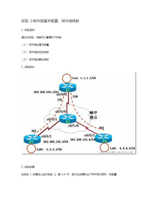
实验2:帧中继基本配置、帧中继映射1. 实验目的通过本实验,读者可以掌握如下技能:(1)帧中继的基本配置(2)帧中继的动态映射(3)帧中继的静态映射2. 实验拓扑3. 实验步骤在实验1 的基础上进行实验2。
图8-4 中,我们已经模拟出了帧中继交换机,现配置R1、R3、R4,使得它们能够互相通信,配置步骤如下:(1) 帧中继接口基本配置R1(config)#int s0/0/0R1(config-if)#ip address 192.168.123.1 255.255.255.0 R1(config-if)#no shutdownR1(config-if)#encapsulation frame-relayR3(config)#int s0/0/1R3(config-if)#ip address 192.168.123.3 255.255.255.0 R3(config-if)#no shutdownR3(config-if)#encapsulation frame-relayR4(config)#int s0/0/1R4(config-if)#ip address 192.168.123.4 255.255.255.0 R4(config-if)#no shutdownR4(config-if)#encapsulation frame-relay(2) 测试连通性从各个路由器ping 其他路由器:R1#ping 192.168.123.3Type escape sequence to abort.Sending 5, 100-byte ICMP Echos to 192.168.123.3, timeout is 2 seconds:!!!!!Success rate is 100 percent (5/5), round-trip min/avg/max = 28/28/28 msR1#ping 192.168.123.4Type escape sequence to abort.Sending 5, 100-byte ICMP Echos to 192.168.123.4, timeout is 2 seconds:!!!!!Success rate is 100 percent (5/5), round-trip min/avg/max = 28/28/28 msR1#show frame-relay mapSerial0/0/0 (up): ip 192.168.123.3 dlci 103(0×67,0×1870), dynamic, broadcast,, status defined, activeSerial0/0/0 (up): ip 192.168.123.4 dlci 104(0×68,0×1880), dynamic, broadcast,, status defined, active//默认时,帧中继接口开启了动态映射,会自动建立帧中继映射, “dynamic”表明这是动态映射。
实验5-帧中继(Frame Relay)配置-(写报告)
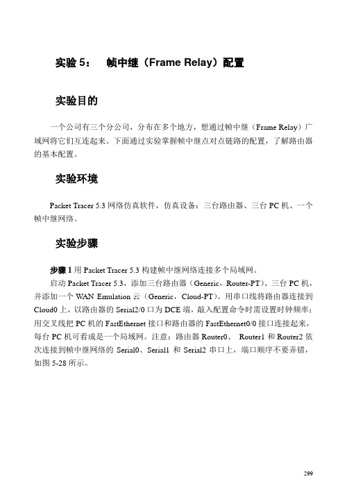
实验5:帧中继(Frame Relay)配置实验目的一个公司有三个分公司,分布在多个地方,想通过帧中继(Frame Relay)广域网将它们互连起来。
下面通过实验掌握帧中继点对点链路的配置,了解路由器的基本配置。
实验环境Packet Tracer 5.3网络仿真软件,仿真设备:三台路由器、三台PC机、一个帧中继网络。
实验步骤步骤1用Packet Tracer 5.3构建帧中继网络连接多个局域网。
启动Packet Tracer 5.3,添加三台路由器(Generic,Router-PT)、三台PC机,并添加一个WAN Emulation云(Generic,Cloud-PT)。
用串口线将路由器连接到Cloud0上,以路由器的Serial2/0口为DCE端,敲入配置命令时需设置时钟频率;用交叉线把PC机的FastEthernet接口和路由器的FastEthernet0/0接口连接起来,每台PC机可看成是一个局域网。
注意:路由器Router0、Router1和Router2依次连接到帧中继网络的Serial0、Serial1和Serial2串口上,端口顺序不要弄错,如图5-28所示。
299图5-28 帧中继配置网络拓扑图步骤2配置PC机的IP地址、子网掩码和默认网关地址。
单击网络拓扑图上的PC0,出现PC0的配置窗口,点击Desktop,点击IP Configuration,按网络拓扑图上所给的IP地址及默认网关地址进行配置,子网掩码采用默认值,如图5-29所示。
300图5-29 PC0的IP配置接着,按如上方法分别对PC1和PC2的IP地址、子网掩码和默认网关进行配置,如图5-30和5-31所示。
图5-30 PC1的IP配置图5-31 PC2的IP配置下面开始配置与帧中继网相连的路由器。
分别对三台路由器的快速以太网口进行配置,对串口进行帧中继封装,配置子接口IP地址和DLCI链路,最后进行路由配置。
为了便于理解配置命令,在某些命令后用//加以注释,读者做实验时301切勿将这些注释也敲进去。
帧中继配置
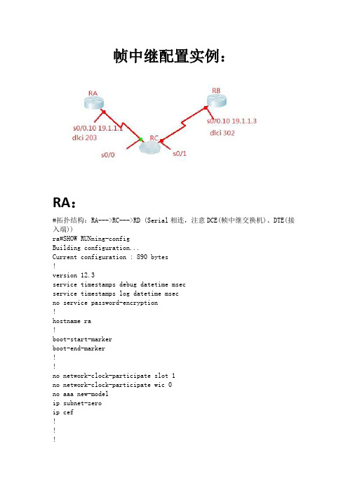
帧中继配置实例:RA:#拓扑结构:RA--->RC--->RD (Serial相连,注意DCE(帧中继交换机)、DTE(接入端))ra#SHOWRUNning-configBuilding configuration...Current configuration : 890 bytes!version 12.3service timestamps debug datetimemsecservice timestamps log datetimemsecno service password-encryption!hostnamera!boot-start-markerboot-end-marker!!no network-clock-participate slot 1no network-clock-participate wic 0noaaa new-modelip subnet-zeroipcef!!!no ftp-server write-enable!!!!interface FastEthernet0/0noip addressshutdownduplex autospeed auto!interface Serial0/0noip addressencapsulation frame-relay IETFno fair-queue!interface Serial0/0.10 multipointip address 19.1.1.1 255.255.255.248ipospf network point-to-multipoint non-broadcast frame-relay map ip 19.1.1.3 203!interface Serial0/1noip address!routerospf 10log-adjacency-changesnetwork 10.1.0.16 0.0.0.3 area 10network 19.1.1.0 0.0.0.7 area 0neighbor 19.1.1.3!ip classlessip http server!!line con 0line aux 0linevty 0 4!!!endra#RB:rb#show running-configBuilding configuration...Current configuration : 1050 bytes!version 12.3service timestamps debug datetimemsecservice timestamps log datetimemsecno service password-encryption!hostnamerb!boot-start-markerboot-end-marker!!no network-clock-participate slot 1no network-clock-participate wic 0noaaa new-modelip subnet-zeroipcef!!!noip domain lookupno ftp-server write-enable!!!!interface FastEthernet0/0ip address 10.1.0.29 255.255.255.248duplex autospeed auto!interface Serial0/0noip addressencapsulation frame-relay IETF!interface Serial0/0.10 multipointip address 19.1.1.3 255.255.255.248ipospf network point-to-multipoint non-broadcastframe-relay map ip 19.1.1.1 302frame-relay interface-dlci 302!interface FastEthernet0/1noip addressshutdownduplex autospeed auto!interface Serial0/1noip addressshutdown!routerospf 10log-adjacency-changesnetwork 10.1.0.28 0.0.0.3 area 10 network 19.1.1.0 0.0.0.7 area 0 neighbor 19.1.1.1neighbor 19.1.1.2!ip classlessnoip http server!!line con 0line aux 0linevty 0 4!!!endRC:rc-zzj#show running-configBuilding configuration...Current configuration : 917 bytes!version 12.3service timestamps debug datetimemsec service timestamps log datetimemsecno service password-encryption!hostnamerc-zzj!boot-start-markerboot-end-marker!!no network-clock-participate slot 1no network-clock-participate wic 0noaaa new-modelip subnet-zeroipcef!!!noip domain lookupframe-relay switchingno ftp-server write-enable!!!!interface FastEthernet0/0noip addressshutdownduplex autospeed auto!interface Serial0/0noip addressencapsulation frame-relay IETFfair-queueclockrate 64000frame-relaylmi-type ansiframe-relayintf-type dceframe-relay route 302 interface Serial0/1 203 !interface Serial0/1noip addressencapsulation frame-relay IETFclockrate 64000frame-relaylmi-type ansiframe-relayintf-type dceframe-relay route 203 interface Serial0/0 302!ip classlessip http server!!line con 0line aux 0linevty 0 4!!!endrc-zzj#查看结果:rb#show frame-relay mapSerial0/0.10 (up): ip 19.1.1.1 dlci 302(0x12E,0x48E0), static,IETF, status defined, activerb#showipospf neighborNeighbor ID Pri State Dead Time Address Interface19.1.1.1 0 FULL/ - 00:01:46 19.1.1.1 Serial0/0.10N/A 0 DOWN/ - - 19.1.1.2 Serial0/0.10rb#ping 19.1.1.1Type escape sequence to abort.Sending 5, 100-byte ICMP Echos to 19.1.1.1, timeout is 2 seconds:!!!!!Success rate is 100 percent (5/5), round-trip min/avg/max = 56/56/56 ms rb#。
实验七.配置帧中继(F-R)
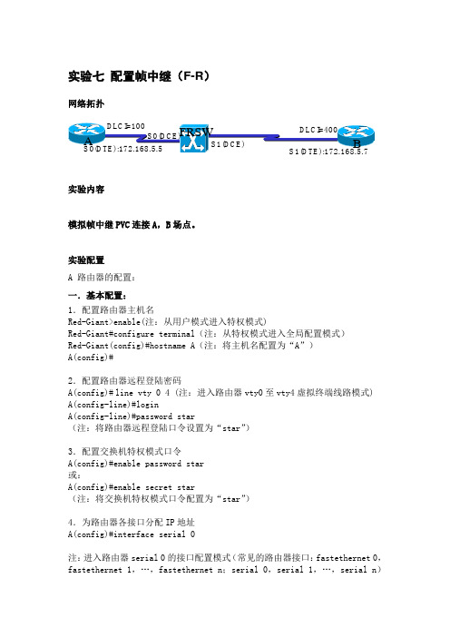
实验七配置帧中继(F-R)网络拓扑实验内容模拟帧中继PVC连接A,B场点。
实验配置A 路由器的配置:一.基本配置:1.配置路由器主机名Red-Giant>enable(注:从用户模式进入特权模式)Red-Giant#configure terminal(注:从特权模式进入全局配置模式)Red-Giant(config)#hostname A(注:将主机名配置为“A”)A(config)#2.配置路由器远程登陆密码A(config)#line vty 0 4 (注:进入路由器vty0至vty4虚拟终端线路模式) A(config-line)#loginA(config-line)#password star(注:将路由器远程登陆口令设置为“star”)3.配置交换机特权模式口令A(config)#enable password star或:A(config)#enable secret star(注:将交换机特权模式口令配置为“star”)4.为路由器各接口分配IP地址A(config)#interface serial 0注:进入路由器serial 0的接口配置模式(常见的路由器接口:fastethernet 0,fastethernet 1,…,fastethernet n;serial 0,serial 1,…,serial n)A(config-if)#ip address 172.168.5.5 255.255.255.0注:设置路由器serial 0的IP地址为172.168.5.5,对应的子网掩码为255.255.255.0二.配置路由器A串口封装协议:A(config-if)#encapsulation frame-relayB 路由器的配置:一.基本配置:1.配置路由器主机名Red-Giant>enable(注:从用户模式进入特权模式)Red-Giant#configure terminal(注:从特权模式进入全局配置模式)Red-Giant(config)#hostname B(注:将主机名配置为“B”)B(config)#2.配置路由器远程登陆密码B(config)#line vty 0 4 (注:进入路由器vty0至vty4虚拟终端线路模式) B(config-line)#loginB(config-line)#password star(注:将路由器远程登陆口令设置为“star”)3.配置交换机特权模式口令B(config)#enable password star或:B(config)#enable secret star(注:将交换机特权模式口令配置为“star”)4.为路由器各接口分配IP地址B(config)#interface serial 0注:进入路由器serial 0的接口配置模式(常见的路由器接口:fastethernet 0,fastethernet 1,…,fastethernet n;serial 0,serial 1,…,serial n)B(config-if)#ip address 172.168.5.7 255.255.255.0注:设置路由器serial 0的IP地址为172.168.5.7,对应的子网掩码为255.255.255.0二.配置路由器B串口封装协议:B(config-if)#encapsulation frame-relayFRSW 路由器的配置:一.基本配置:配置路由器主机名Red-Giant>enable(注:从用户模式进入特权模式)Red-Giant#configure terminal(注:从特权模式进入全局配置模式)Red-Giant(config)#hostname FRSW(注:将主机名配置为“B”)FRSW(config)#二.配置FR交换特性:FRSW(config)#frame-relay switching注:将路由器模拟为帧中继交换设备FRSW(config)#interface serial 1注:进入路由器serial 1的接口配置模式(常见的路由器接口:fastethernet 0,fastethernet 1,…,fastethernet n;serial 0,serial 1,…,serial n)FRSW(config-if)#clock rate 64000注:设置serial 1接口物理时钟频率为64KbpsFRSW(config-if)#encapsulation frame-relay注:设置serial 1接口的封装协议为帧中继FRSW(config-if)#frame-relay intf-type dce注:使serial 1接口具有帧中继交换特性FRSW(config-if)frame-relay route 400 interface serial 0 100注:“400”为入口的DLCI编号;“serial 0”为出口“100”为出口的DLCI编号。
帧中继的配置
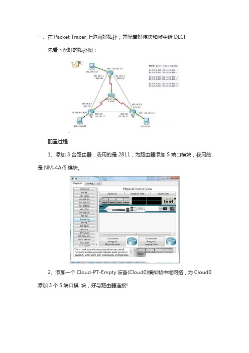
一、在Packet Tracer上边画好拓扑,并配置好模块和帧中继DLCI先看下配好的拓扑图:配置过程:1、添加3台路由器,我用的是2811,为路由器添加S端口模块,我用的是NM-4A/S模块。
2、添加一个Cloud-PT-Empty设备(Cloud0)模拟帧中继网络,为Cloud0添加3个S端口模块,好与路由器连接!3、设置好S1,S2,S3,的DLCI值:??4、配置好Frame-relay连接:?5、连接端口注意:路由器作为DTE设备,Cloud0作为DCE设备,按照拓扑添加3台PC作测试用,连接到路由器F端口,并启动各连接端口。
为各PC设置好IP和网关:?做好ip地址的规划,网络拓扑就基本完成了,下面进行路由器的配置二、配置3台路由器:R1路由器配置:R1>enR1#conf tR1(config)#int s1/0?????????????????????????????????? 进入S1/0端口配置R1(config-if)#no shut???????????????????????????????? 启动端口R1(config-if)#encapsulation frame-relay?????????????? 帧中继封装R1(config-if)#frame-relay lmi-type cisco????????????? 帧中继类型为ciscoR1(config)#int s1/0.1 point-to-point????????????????? 配置子端口,并设置为点对点模式R1(config-subif)#ip add 192.168.1.1 255.255.255.0???? 分配子端口ip 地址R1(config-subif)#frame-relay interface-dlci 102?????? 指定点对点对应的DLCI值R1(config-subif)#exitR1(config)#int s1/0.2 point-to-point????????????????? 配置子端口,并设置为点对点模式R1(config-subif)#ip add 192.168.2.1 255.255.255.0???? 分配子端口ip 地址R1(config-subif)#frame-relay interface-dlci 103?????? 指定点对点对应的DLCI值R1(config-subif)#exitR2路由器配置:R2>enR2#conf tR2(config)#int s1/0R2(config-if)#no shutR2(config-if)#en frame-relayR2(config-if)#frame-relay lmi-type ciscoR2(config)#int s1/0.1 point-to-pointR2(config-subif)#ip add 192.168.1.2 255.255.255.0 R2(config-subif)#frame-relay interface-dlci 201R2(config-subif)#exitR2(config)#int s1/0.2 pR2(config-subif)#ip add 192.168.3.1 255.255.255.0 R2(config-subif)#frame-relay interface-dlci 203R2(config-subif)#exitR3路由器配置:R3>enR3#conf tR3(config)#int s1/0R3(config-if)#no shutR3(config-if)#en frame-relayR3(config-if)#frame-relay lmi-type ciscoR3(config)#int s1/0.1 point-to-pointR3(config-subif)#ip add 192.168.3.2 255.255.255.0 R3(config-subif)#frame-relay interface-dlci 302R3(config-subif)#exitR3(config)#int s1/0.2 point-to-pointR3(config-subif)#ip add 192.168.2.2 255.255.255.0R3(config-subif)#frame-relay interface-dlci 301R3(config-subif)#exit在三台路由器上启动rip路由:R1(config)#router rip???????????????????????????????? 启动rip路由R1(config-router)#net 192.168.10.0??????????????????? 申明接口网络地址R1(config-router)#net 192.168.1.0???????????????????? 申明接口网络地址R1(config-router)#net 192.168.2.0???????????????????? 申明接口网络地址R1(config-router)#exitR1(config)#R2(config)#router ripR2(config-router)#net 192.168.20.0R2(config-router)#net 192.168.1.0R2(config-router)#net 192.168.3.0R2(config-router)#exitR2(config)#R3(config)#router ripR3(config-router)#net 192.168.30.0R3(config-router)#net 192.168.3.0R3(config-router)#net 192.168.2.0R3(config-router)#exitR3(config)#exitRouter#完成配置后,用PC1~3检验是否成功,实验完成!。
帧中继协议原理及配置
帧中继协议原理及配置【复习旧课】(教学手段:课堂提问)【引入新课】(教学手段:创设情景)【讲授新课】(教学手段:教师讲授)帧中继概述帧中继(Frame Relay,简称FR)是以X.25分组交换技术为基础,摒弃其中复杂的检、纠错过程,改造了原有的帧结构,从而获得了良好的性能。
帧中继的用户接入速率一般为64 kbps〜2 Mbps,局间中继传输速率一般为2 Mbps、34 Mbps,现已可达155 Mbps。
1. 帧中继简介帧中继技术继承了X.25提供的统计复用功能和采用虚电路交换的优点,但是简化了可靠传输和差错控制机制,将那些用于保证数据可靠性传输的任务(如流量控制和差错控制等)委托给用户终端或本地结点机来完成,从而在减少网络时延的同时降低了通信成本。
帧中继中的虚电路是帧中继包交换网络为实现不同DTE之间的数据传输所建立的逻辑链路,这种虚电路可以在帧中继交换网络内跨越任意多个DCE设备或帧中继交换机。
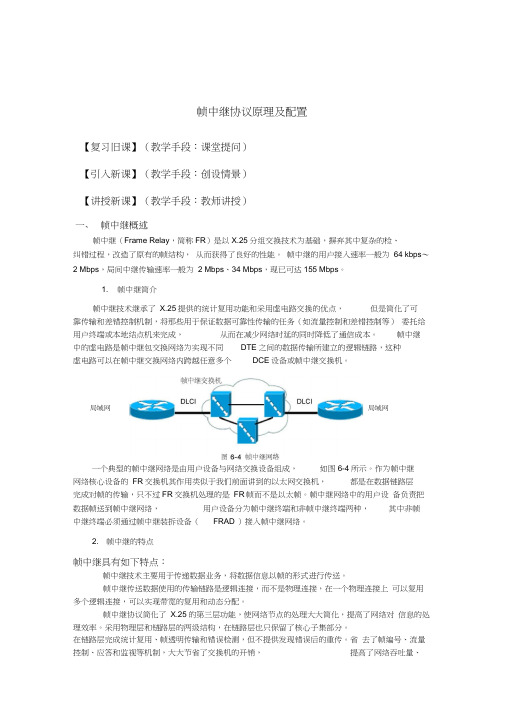
局域网局域网一个典型的帧中继网络是由用户设备与网络交换设备组成,如图6-4所示。
作为帧中继网络核心设备的FR交换机其作用类似于我们前面讲到的以太网交换机,都是在数据链路层完成对帧的传输,只不过FR交换机处理的是FR帧而不是以太帧。
帧中继网络中的用户设备负责把数据帧送到帧中继网络,用户设备分为帧中继终端和非帧中继终端两种,其中非帧中继终端必须通过帧中继装拆设备(FRAD )接入帧中继网络。
2. 帧中继的特点帧中继具有如下特点:帧中继技术主要用于传递数据业务,将数据信息以帧的形式进行传送。
帧中继传送数据使用的传输链路是逻辑连接,而不是物理连接,在一个物理连接上可以复用多个逻辑连接,可以实现带宽的复用和动态分配。
帧中继协议简化了X.25的第三层功能,使网络节点的处理大大简化,提高了网络对信息的处理效率。
采用物理层和链路层的两级结构,在链路层也只保留了核心子集部分。
在链路层完成统计复用、帧透明传输和错误检测,但不提供发现错误后的重传。
- 1、下载文档前请自行甄别文档内容的完整性,平台不提供额外的编辑、内容补充、找答案等附加服务。
- 2、"仅部分预览"的文档,不可在线预览部分如存在完整性等问题,可反馈申请退款(可完整预览的文档不适用该条件!)。
- 3、如文档侵犯您的权益,请联系客服反馈,我们会尽快为您处理(人工客服工作时间:9:00-18:30)。
实验三:帧中继配置一、实验目的:掌握用户边缘设备(CE)上帧中继接口的配置方法、掌握Hub-Spoke网络中RIP的配置方法、掌握Hub-Spoke(NBMA)网络中OSF的配置方法和掌握点到多点网络中OSPF 的配置方法。
二、实验拓扑图:三、实验配置命令:1、路由器R1的配置命令:<Huawei>sys[Huawei]sysname R1[R1]interface Serial 0/0/0[R1-Serial0/0/0]link-protocol frContinue? [Y/N]:y[R1-Serial0/0/0]ip address 10.0.123.1 24[R1-Serial0/0/0][R1-Serial0/0/0]undo fr inarp[R1-Serial0/0/0][R1-Serial0/0/0]fr map ip 10.0.123.2 102 broadcast[R1-Serial0/0/0][R1-Serial0/0/0]fr map ip 10.0.123.3 103 broadcast[R1-Serial0/0/0][R1-Serial0/0/0]interface loopback 0[R1-LoopBack0][R1-LoopBack0]ip address 10.0.1.1 24[R1-LoopBack0][R1-LoopBack0]quit[R1]quit<R1>ping 10.0.123.2PING 10.0.123.2: 56 data bytes, press CTRL_C to breakReply from 10.0.123.2: bytes=56 Sequence=1 ttl=255 time=50 ms Reply from 10.0.123.2: bytes=56 Sequence=2 ttl=255 time=10 ms Reply from 10.0.123.2: bytes=56 Sequence=3 ttl=255 time=60 ms Reply from 10.0.123.2: bytes=56 Sequence=4 ttl=255 time=50 ms Reply from 10.0.123.2: bytes=56 Sequence=5 ttl=255 time=50 ms--- 10.0.123.2 ping statistics ---5 packet(s) transmitted5 packet(s) received0.00% packet lossround-trip min/avg/max = 10/44/60 ms<R1>ping 10.0.123.3PING 10.0.123.3: 56 data bytes, press CTRL_C to breakReply from 10.0.123.3: bytes=56 Sequence=1 ttl=255 time=30 ms Reply from 10.0.123.3: bytes=56 Sequence=2 ttl=255 time=40 ms Reply from 10.0.123.3: bytes=56 Sequence=3 ttl=255 time=30 ms Reply from 10.0.123.3: bytes=56 Sequence=4 ttl=255 time=50 ms Reply from 10.0.123.3: bytes=56 Sequence=5 ttl=255 time=50 ms--- 10.0.123.3 ping statistics ---5 packet(s) transmitted5 packet(s) received0.00% packet lossround-trip min/avg/max = 30/40/50 ms<R1>display fr interface Serial 0/0/0Serial0/0/0, DTE, physical up, protocol up<R1>display fr lmi-info interface serial 0/0/0<R1><R1>display fr map-info interface serial 0/0/0[R1]rip 1[R1-rip-1]version 2[R1-rip-1]network 10.0.0.0[R1-rip-1][R1-rip-1]undo summary[R1-rip-1][R1-rip-1]quit[R1]quit<R1>display ip routing-table protocol ripRoute Flags: R - relay, D - download to fib------------------------------------------------------------------------------Public routing table : RIPDestinations : 1 Routes : 1RIP routing table status : <Active>Destinations : 1 Routes : 1Destination/Mask Proto Pre Cost Flags NextHop Interface10.0.2.0/24 RIP 100 1 D 10.0.123.2 Serial0/0/0RIP routing table status : <Inactive>Destinations : 0 Routes : 0<R1>display ip routing-tableRoute Flags: R - relay, D - download to fib------------------------------------------------------------------------------Routing Tables: PublicDestinations : 9 Routes : 9Destination/Mask Proto Pre Cost Flags NextHop Interface10.0.1.0/24 Direct 0 0 D 10.0.1.1 LoopBack010.0.1.1/32 Direct 0 0 D 127.0.0.1 LoopBack010.0.2.0/24 RIP 100 1 D 10.0.123.2 Serial0/0/010.0.123.0/24 Direct 0 0 D 10.0.123.1 Serial0/0/010.0.123.1/32 Direct 0 0 D 127.0.0.1 Serial0/0/010.0.123.2/32 Direct 0 0 D 10.0.123.2 Serial0/0/010.0.123.3/32 Direct 0 0 D 10.0.123.3 Serial0/0/0127.0.0.0/8 Direct 0 0 D 127.0.0.1 InLoopBack0 127.0.0.1/32 Direct 0 0 D 127.0.0.1 InLoopBack0<R1>sys[R1]undo rip 1Warning: The RIP process will be deleted. Continue?[Y/N]y[R1]Dec 6 2014 16:35:41-08:00 R1 DS/4/DA TASYNC_CFGCHANGE:OID 1.3.6.1.4.1.2011.5.25.1 91.3.1 configurations have been changed. The current change number is 15, the change loop count is 0, and the maximum number of records is 4095.[R1]ospf 1 router-id 10.0.1.1[R1-ospf-1]area 0[R1-ospf-1-area-0.0.0.0]network 10.0.0.0 0.255.255.255[R1-ospf-1-area-0.0.0.0][R1-ospf-1-area-0.0.0.0]quit[R1-ospf-1]quit[R1]ospf[R1-ospf-1]peer 10.0.123.2[R1-ospf-1][R1-ospf-1]peer 10.0.123.3[R1-ospf-1][R1-ospf-1]interface serial 0/0/0[R1-Serial0/0/0]ospf dr-priority 255[R1-Serial0/0/0][R1-Serial0/0/0][R1-Serial0/0/0]quit[R1]quit<R1>display ospf interface Serial 0/0/0 verboseOSPF Process 1 with Router ID 10.0.1.1InterfacesInterface: 10.0.123.1 (Serial0/0/0)Cost: 1562 State: DR Type: NBMA MTU: 1500Priority: 255Designated Router: 10.0.123.1Backup Designated Router: 10.0.123.3Timers: Hello 30 , Dead 120 , Poll 120 , Retransmit 5 , Transmit Delay 1IO StatisticsType Input OutputHello 9 14DB Description 4 6Link-State Req 2 2Link-State Update 6 11Link-State Ack 7 2OpaqueId: 0 PrevState: Waiting<R1>reset ospf process graceful-restart^Error:Too many parameters found at '^' position.<R1>display ip routing-tableRoute Flags: R - relay, D - download to fib------------------------------------------------------------------------------Routing Tables: PublicDestinations : 10 Routes : 10Destination/Mask Proto Pre Cost Flags NextHop Interface10.0.1.0/24 Direct 0 0 D 10.0.1.1 LoopBack010.0.1.1/32 Direct 0 0 D 127.0.0.1 LoopBack010.0.2.2/32 OSPF 10 1562 D 10.0.123.2 Serial0/0/010.0.3.3/32 OSPF 10 1562 D 10.0.123.3 Serial0/0/010.0.123.0/24 Direct 0 0 D 10.0.123.1 Serial0/0/010.0.123.1/32 Direct 0 0 D 127.0.0.1 Serial0/0/010.0.123.2/32 Direct 0 0 D 10.0.123.2 Serial0/0/010.0.123.3/32 Direct 0 0 D 10.0.123.3 Serial0/0/0127.0.0.0/8 Direct 0 0 D 127.0.0.1 InLoopBack0 127.0.0.1/32 Direct 0 0 D 127.0.0.1 InLoopBack0<R1>ping -a 10.0.1.1 10.0.2.2PING 10.0.2.2: 56 data bytes, press CTRL_C to breakReply from 10.0.2.2: bytes=56 Sequence=1 ttl=255 time=30 msReply from 10.0.2.2: bytes=56 Sequence=2 ttl=255 time=40 msReply from 10.0.2.2: bytes=56 Sequence=3 ttl=255 time=30 msReply from 10.0.2.2: bytes=56 Sequence=4 ttl=255 time=50 msReply from 10.0.2.2: bytes=56 Sequence=5 ttl=255 time=10 ms--- 10.0.2.2 ping statistics ---5 packet(s) transmitted5 packet(s) received0.00% packet lossround-trip min/avg/max = 10/32/50 ms<R1>sys[R1]ospf[R1-ospf-1]undo peer 10.0.123.2[R1-ospf-1][R1-ospf-1]undo peer 10.0.123.3[R1-ospf-1]quit[R1]interface s[R1]interface Serial 0/0/0[R1-Serial0/0/0]ospf network-type p2mp[R1-Serial0/0/0][R1-Serial0/0/0]quit[R1]quit<R1>display ospf peer briefOSPF Process 1 with Router ID 10.0.1.1Peer Statistic Information----------------------------------------------------------------------------Area Id Interface Neighbor id State0.0.0.0 Serial0/0/0 10.0.2.2 Full0.0.0.0 Serial0/0/0 10.0.3.3 Full----------------------------------------------------------------------------<R1>display ip routing-tableRoute Flags: R - relay, D - download to fib------------------------------------------------------------------------------Routing Tables: PublicDestinations : 10 Routes : 10Destination/Mask Proto Pre Cost Flags NextHop Interface10.0.1.0/24 Direct 0 0 D 10.0.1.1 LoopBack010.0.1.1/32 Direct 0 0 D 127.0.0.1 LoopBack010.0.2.2/32 OSPF 10 1562 D 10.0.123.2 Serial0/0/010.0.3.3/32 OSPF 10 1562 D 10.0.123.3 Serial0/0/010.0.123.0/24 Direct 0 0 D 10.0.123.1 Serial0/0/010.0.123.1/32 Direct 0 0 D 127.0.0.1 Serial0/0/010.0.123.2/32 Direct 0 0 D 10.0.123.2 Serial0/0/010.0.123.3/32 Direct 0 0 D 10.0.123.3 Serial0/0/0127.0.0.0/8 Direct 0 0 D 127.0.0.1 InLoopBack0 127.0.0.1/32 Direct 0 0 D 127.0.0.1 InLoopBack02、路由器R2的配置命令:<Huawei>sys[Huawei]sysname R2[R2][R2]interface Serial 0/0/0[R2-Serial0/0/0]link-protocol frContinue? [Y/N]:y[R2-Serial0/0/0][R2-Serial0/0/0]ip address 10.0.123.2 24[R2-Serial0/0/0][R2-Serial0/0/0]undo fr inarp[R2-Serial0/0/0][R2-Serial0/0/0]fr map ip 10.0.123.1 201 broadcast[R2-Serial0/0/0][R2-Serial0/0/0]interface loopback 0[R2-LoopBack0][R2-LoopBack0]ip address 10.0.2.2 24[R2-LoopBack0][R2-LoopBack0]quit[R2]rip 1[R2-rip-1]version 2[R2-rip-1]network 10.0.0.0[R2-rip-1][R2-rip-1]undo summary[R2-rip-1][R2-rip-1]quit[R2]quit<R2>display ip routing-table protocol ripRoute Flags: R - relay, D - download to fib------------------------------------------------------------------------------Public routing table : RIPDestinations : 1 Routes : 1RIP routing table status : <Active>Destinations : 1 Routes : 1Destination/Mask Proto Pre Cost Flags NextHop Interface10.0.1.0/24 RIP 100 1 D 10.0.123.1 Serial0/0/0RIP routing table status : <Inactive>Destinations : 0 Routes : 0<R2>display ip routing-tableRoute Flags: R - relay, D - download to fib------------------------------------------------------------------------------Routing Tables: PublicDestinations : 8 Routes : 8Destination/Mask Proto Pre Cost Flags NextHop Interface10.0.1.0/24 RIP 100 1 D 10.0.123.1 Serial0/0/010.0.2.0/24 Direct 0 0 D 10.0.2.2 LoopBack010.0.2.2/32 Direct 0 0 D 127.0.0.1 LoopBack010.0.123.0/24 Direct 0 0 D 10.0.123.2 Serial0/0/010.0.123.1/32 Direct 0 0 D 10.0.123.1 Serial0/0/010.0.123.2/32 Direct 0 0 D 127.0.0.1 Serial0/0/0127.0.0.0/8 Direct 0 0 D 127.0.0.1 InLoopBack0 127.0.0.1/32 Direct 0 0 D 127.0.0.1 InLoopBack0<R2>sys[R2]interface serial 0/0/0[R2-Serial0/0/0]fr map ip 10.0.123.3 24[R2-Serial0/0/0][R2-Serial0/0/0]quit[R2]interface serial 0/0/0[R2-Serial0/0/0]undo fr map ip 10.0.123.3 201^[R2-Serial0/0/0]undo fr map ip 10.0.123.3 201[R2-Serial0/0/0]quit[R2]ospf 1 router-id 10.0.2.2[R2-ospf-1]a[R2-ospf-1]area 0[R2-ospf-1-area-0.0.0.0][R2-ospf-1-area-0.0.0.0]network 10.0.0.0 0.255.255.255[R2-ospf-1-area-0.0.0.0][R2-ospf-1-area-0.0.0.0]quit[R2-ospf-1]quit[R2]ospf[R2-ospf-1]peer 10.0.123.1[R2-ospf-1][R2-ospf-1]quit[R2]ospf[R2-ospf-1]undo peer 10.0.123.1[R2-ospf-1][R2-ospf-1]quit[R2]interface s[R2]interface Serial 0/0/0[R2-Serial0/0/0]ospf network-type p2mp[R2-Serial0/0/0]quit[R2]quit<R2>display ospf peer briefOSPF Process 1 with Router ID 10.0.2.2Peer Statistic Information----------------------------------------------------------------------------Area Id Interface Neighbor id State0.0.0.0 Serial0/0/0 10.0.1.1 Full----------------------------------------------------------------------------<R2>display ip routing-tableRoute Flags: R - relay, D - download to fib------------------------------------------------------------------------------Routing Tables: PublicDestinations : 10 Routes : 10Destination/Mask Proto Pre Cost Flags NextHop Interface10.0.1.1/32 OSPF 10 1562 D 10.0.123.1 Serial0/0/010.0.2.0/24 Direct 0 0 D 10.0.2.2 LoopBack010.0.2.2/32 Direct 0 0 D 127.0.0.1 LoopBack010.0.3.3/32 OSPF 10 3124 D 10.0.123.1 Serial0/0/010.0.123.0/24 Direct 0 0 D 10.0.123.2 Serial0/0/010.0.123.1/32 Direct 0 0 D 10.0.123.1 Serial0/0/010.0.123.2/32 Direct 0 0 D 127.0.0.1 Serial0/0/010.0.123.3/32 OSPF 10 3124 D 10.0.123.1 Serial0/0/0127.0.0.0/8 Direct 0 0 D 127.0.0.1 InLoopBack0 127.0.0.1/32 Direct 0 0 D 127.0.0.1 InLoopBack03、路由器R3的配置命令:<Huawei>sys[Huawei]sysname R3[R3]interface Serial 0/0/0[R3-Serial0/0/0]link-protocol frContinue? [Y/N]:y[R3-Serial0/0/0][R3-Serial0/0/0]undo fr inarp[R3-Serial0/0/0][R3-Serial0/0/0]fr map ip 10.0.123.1 301 broadcast[R3-Serial0/0/0][R3-Serial0/0/0]interface loopback 0[R3-LoopBack0][R3-LoopBack0]ip address 10.0.3.3 24[R3-LoopBack0][R3-LoopBack0]quit[R3]rip 1[R3-rip-1][R3-rip-1]net[R3-rip-1]network 10.0.0.0[R3-rip-1][R3-rip-1]undo summary[R3-rip-1][R3-rip-1]quit[R3]quit<R3>display ip routing-table protocol ripRoute Flags: R - relay, D - download to fib------------------------------------------------------------------------------Public routing table : RIPDestinations : 2 Routes : 2RIP routing table status : <Active>Destinations : 2 Routes : 2Destination/Mask Proto Pre Cost Flags NextHop Interface10.0.1.0/24 RIP 100 1 D 10.0.123.1 Serial0/0/010.0.2.0/24 RIP 100 2 D 10.0.123.1 Serial0/0/0 RIP routing table status : <Inactive>Destinations : 0 Routes : 0<R3>sys<R3>display ip routing-tableRoute Flags: R - relay, D - download to fib------------------------------------------------------------------------------Routing Tables: PublicDestinations : 9 Routes : 9Destination/Mask Proto Pre Cost Flags NextHop Interface10.0.1.0/24 RIP 100 1 D 10.0.123.1 Serial0/0/010.0.2.0/24 RIP 100 2 D 10.0.123.1 Serial0/0/010.0.3.0/24 Direct 0 0 D 10.0.3.3 LoopBack010.0.3.3/32 Direct 0 0 D 127.0.0.1 LoopBack010.0.123.0/24 Direct 0 0 D 10.0.123.3 Serial0/0/010.0.123.1/32 Direct 0 0 D 10.0.123.1 Serial0/0/010.0.123.3/32 Direct 0 0 D 127.0.0.1 Serial0/0/0127.0.0.0/8 Direct 0 0 D 127.0.0.1 InLoopBack0 127.0.0.1/32 Direct 0 0 D 127.0.0.1 InLoopBack0<R3>display fr map-info interface s<R3>display fr map-info interface Serial 0/0/0<R3>sys[R3]interface serial 0/0/0[R3-Serial0/0/0]fr map ip 10.0.123.2 301[R3-Serial0/0/0][R3-Serial0/0/0]quit[R3]quit<R3>sys[R3]interface Serial 0/0/0[R3-Serial0/0/0]undo fr map ip 10.0.123.2 301[R3-Serial0/0/0]quit[R3][R3]undo rip 1Warning: The RIP process will be deleted. Continue?[Y/N]y[R3][R3]ospf 1 router-id 10.0.3.3[R3-ospf-1]area 0[R3-ospf-1-area-0.0.0.0][R3-ospf-1-area-0.0.0.0]network 10.0.0.0 0.255.255.255[R3-ospf-1-area-0.0.0.0][R3-ospf-1-area-0.0.0.0]quit[R3-ospf-1]quit[R3]quit<R3>display ospf interface serial 0/0/0 verboseOSPF Process 1 with Router ID 10.0.3.3InterfacesInterface: 10.0.123.3 (Serial0/0/0)Cost: 1562 State: Waiting Type: NBMA MTU: 1500Priority: 1Designated Router: 0.0.0.0Backup Designated Router: 0.0.0.0Timers: Hello 30 , Dead 120 , Poll 120 , Retransmit 5 , Transmit Delay 1IO StatisticsType Input OutputHello 0 0DB Description 0 0Link-State Req 0 0Link-State Update 0 0Link-State Ack 0 0OpaqueId: 0 PrevState: Down<R3>sys[R3]ospf[R3-ospf-1]peer 10.0.123.1[R3-ospf-1][R3-ospf-1][R3-ospf-1]quit[R3]ospf[R3-ospf-1]undo peer 10.0.123.1[R3-ospf-1][R3-ospf-1]quit[R3]interface s[R3]interface Serial 0/0/0[R3-Serial0/0/0]ospf network-type p2mp[R3-Serial0/0/0][R3-Serial0/0/0]quit[R3]quit<R3>display ospf peer briefOSPF Process 1 with Router ID 10.0.3.3Peer Statistic Information----------------------------------------------------------------------------Area Id Interface Neighbor id State0.0.0.0 Serial0/0/0 10.0.1.1 Full----------------------------------------------------------------------------<R3>display ip routing-tableRoute Flags: R - relay, D - download to fib------------------------------------------------------------------------------Routing Tables: PublicDestinations : 10 Routes : 10Destination/Mask Proto Pre Cost Flags NextHop Interface10.0.1.1/32 OSPF 10 1562 D 10.0.123.1 Serial0/0/010.0.2.2/32 OSPF 10 3124 D 10.0.123.1 Serial0/0/010.0.3.0/24 Direct 0 0 D 10.0.3.3 LoopBack010.0.3.3/32 Direct 0 0 D 127.0.0.1 LoopBack010.0.123.0/24 Direct 0 0 D 10.0.123.3 Serial0/0/010.0.123.1/32 Direct 0 0 D 10.0.123.1 Serial0/0/010.0.123.2/32 OSPF 10 3124 D 10.0.123.1 Serial0/0/010.0.123.3/32 Direct 0 0 D 127.0.0.1 Serial0/0/0127.0.0.0/8 Direct 0 0 D 127.0.0.1 InLoopBack0 127.0.0.1/32 Direct 0 0 D 127.0.0.1 InLoopBack0 <R3>ping -a 10.0.3.3 10.0.1.1PING 10.0.1.1: 56 data bytes, press CTRL_C to breakReply from 10.0.1.1: bytes=56 Sequence=1 ttl=255 time=20 msReply from 10.0.1.1: bytes=56 Sequence=2 ttl=255 time=40 msReply from 10.0.1.1: bytes=56 Sequence=3 ttl=255 time=10 msReply from 10.0.1.1: bytes=56 Sequence=4 ttl=255 time=40 msReply from 10.0.1.1: bytes=56 Sequence=5 ttl=255 time=30 ms--- 10.0.1.1 ping statistics ---5 packet(s) transmitted5 packet(s) received0.00% packet lossround-trip min/avg/max = 10/28/40 ms<R3>ping -a 10.0.3.3 10.0.123.2PING 10.0.123.2: 56 data bytes, press CTRL_C to breakReply from 10.0.123.2: bytes=56 Sequence=1 ttl=254 time=50 msReply from 10.0.123.2: bytes=56 Sequence=2 ttl=254 time=60 msReply from 10.0.123.2: bytes=56 Sequence=3 ttl=254 time=40 msReply from 10.0.123.2: bytes=56 Sequence=4 ttl=254 time=50 msReply from 10.0.123.2: bytes=56 Sequence=5 ttl=254 time=30 ms--- 10.0.123.2 ping statistics ---5 packet(s) transmitted5 packet(s) received0.00% packet lossround-trip min/avg/max = 30/46/60 ms<R3>ping -a 10.0.3.3 10.0.2.2PING 10.0.2.2: 56 data bytes, press CTRL_C to breakReply from 10.0.2.2: bytes=56 Sequence=1 ttl=254 time=60 ms Reply from 10.0.2.2: bytes=56 Sequence=2 ttl=254 time=60 ms Reply from 10.0.2.2: bytes=56 Sequence=3 ttl=254 time=20 ms Reply from 10.0.2.2: bytes=56 Sequence=4 ttl=254 time=60 ms Reply from 10.0.2.2: bytes=56 Sequence=5 ttl=254 time=50 ms --- 10.0.2.2 ping statistics ---5 packet(s) transmitted5 packet(s) received0.00% packet lossround-trip min/avg/max = 20/50/60 ms。
