Agilent U8000A系列单路输出直流电源
Agilent E364xA系列可编程DC电压源数据手册说明书

Agilent Technologies E3640A – E3649A Programmable DC Power SuppliesData SheetGreat Performance, Outstanding Price With 30 to 100W of output power, the Agilent E364xA-series ofprogrammable DC power supplies provide great performance at a great price. All ten models deliver clean power, dependable regulation, fast transient response and built-in GPIB and RS-232 interfaces. They’re designed to meet the needs of R&D design verification, production testing, QA verifications and other demandingapplications with Agilent Technologies’quality and reliability.Steady OutputWith 0.01 percent load and line regulation, Agilent E364xA power supplies keep output steady when power line and load changes occur.They also specify low normal mode voltage noise and low common mode current noise. The low normal mode noise specification assures clean power for precision circuitry applications, and the low common mode currentprovides isolation from power line current injection. Agilent E364xA power supplies specify less than 90msec of voltage settling time at any output load condition.Remote InterfaceAgilent E364xA power supplies support any PC with a GPIB (IEEE-488) card or RS-232 interface. Every model ships standard with both GPIB and RS-232.Easy-to-use SCPI (Standard Commands for Programmable Instruments) keeps programming fast and simple. The user manual provides information for beginning programmers, yet includes enough detail to help veteran programmers as well. Broad SupportVXIplug&play software drivers are available for Agilent VEE and National Instruments LabView™ andLabWindows™, simplifying integration of the E364xA into your test system.The drivers are supported under Microsoft ®Windows 98®and NT.®Front Panel OperationAn easy-to-use rotary knob and self-guiding keypads allow you to quickly and easily set output at the resolution you need. Voltage and current levels can be set to a maximum resolution of 10mV/1 mA from the front panel. Up to five complete power supply setups can be stored and recalled from the internal non-volatile memory. The output on/off button sets the output to zero. Dual output models allow two voltages or currents to be displayed simultaneously. Versatile PowerAgilent E364xA power supplies give you the flexibility to select from dual output ranges. Output load is protected against overvoltage, which is easily monitored and adjusted from the front panel and remote interface. Remote sensing is available in the rear terminal to eliminate errors due to voltage drops on the load leads. These power supplies offer new versatile bindingClean Programmable Power Supplies • Single and Dual Output • Dual Output Ranges • 30W to 100W Output Power • Front and Rear Output Terminals • Over-voltage Protection • Remote Sense• GPIB and RS-232 Standardposts on the front panel and screw-type terminals on the rear panel. New front panel binding posts allow you to use safety test leads as well as conventional banana clips and stripped wires. An optional rackmount kit is available. The Agilent E364xA series employs a cooling fan with automatic speed control for reduced acoustic noise. LabView and LabWindows are registered trademarks ofNational Instruments.Microsoft, Windows 98 and Windows NT are US registered trademarks of Microsoft Corp.Highly visible vacuum flourescent displaySelectable dual range provides flexibility and convenience3-year warranty protects yourBuilt-in GPIB and RS-232 interfaces Rotary knob for quick and analog-like control of voltage and currentVersatile binding posts offer flexibility to use safety test leads, banana plugs orRear output and sensing terminals Cooling fan with automatic speed control for low acoustic noiseTough handlefor easycarriage andunit prop-up2Agilent E3640A – E3649A Programmable DC Power Supply SpecificationsModel Number E3640A E3641A E3642A E3643A E3644A E3645AMaximum Power30W50W80W# of Output111111DC Output Rating0 to 8V/3A or0 to 35V/0.8A or0 to 8V/5A or0 to 35V/1.4A or 0 to 8V/8A or0 to 35V/2.2A or(@ 0°C to 40°C)0 to 20V/1.5A0 to 60V/0.5A0 to 20V/2.5A0 to 60V/0.8A0 to 20V/4A0 to 60V/1.3ANet Weight 5.3kg (11.7 lbs) 6.2kg (13.7 lbs) 6.7 kg (14.7 lbs)Dimension254.4mmW x 103.6mmH x 374mmD (10 x 4.1 x 14.7 in)Model Number E3646A E3647A E3648A E3649AMaximum Power60W100W# of Output2222DC Output Rating Two Two Two Two (@ 0°C to 40°C)0 to 8V/3A or0 to 35V/0.8A or 0 to 8V/5A or0 to 35V/1.4A or0 to 20V/1.5A0 to 60V/0.5A0 to 20V/2.5A60V/0.8ANet Weight7.3kg (16.1 lbs)9.2kg (20.3 lbs)Dimension228mm W x 133mm H x 374mm D (8.9 x 5.2 x 14.7 in)Load1and Line Regulation±(% of output + offset)Voltage<0.01% + 3mVCurrent<0.01% + 250uARipple and Noise(20Hz to 20MHz)Normal Mode Voltage<5mVpp/0.5mVrms for 8V/20V models<8mVpp/1mVrms for 35V/60V modelsNormal Mode Current<4mArmsCommon Mode Current<1.5uArmsAccuracy 12 Months (@ 25 °C ±5 °C), ±(% output + offset)ProgrammingVoltage<0.05% + 10mV (<0.1% + 25mV for output 2 of E3646/47/48/49A)Current<0.2% + 10mAReadbackVoltage <0.05% + 5mV (<0.1% + 25mV for output 2 of E3646/47/48/49A)Current<0.15% + 5mA (<0.15% + 10mA for output 2 of E3646/47/48/49A)ResolutionProgram<5mV / 1mAReadback<2mV / 1mAMeter10mV / 1mATransient Response Less than 50µsec for output to recover to within 15mV following a change in outputcurrent from full load to half load or vice versa.Settling Time 2<90msecOVPAccuracy,<0.5% + 0.5V±(% output + offset)Activation time3<1.5msec, OVP≥3V / <10msec, OVP< 3VTemperature Coefficient per °C±(% output + offset)Voltage<0.01% + 3mV (<0.02% + 5mV for output 2 of E3646/47/48/49A)Current<0.02% + 3mAStability, constant output & temperature ±(% of output + offset), 8 hrsVoltage <0.02%+2mVCurrent<0.1% + 1mARemote Sense 1VMax voltage drop in each load leadAC Input 100Vac ±10% (Opt 0E9) / 115Vac ±10% (Std) / 230Vac ±10% (Opt 0E3)(47Hz – 63Hz)Warranty 3 yearsProduct Regulation Designed to comply with UL3111-1; certified to CSA 22.2 No. 1010.1; conforms toIEC 1010-1; complies with EMC directive 89/336/EEC(Group1, Class A)1With sense terminal connected.2Maximum time required for the output voltage to change from 1% to 99% or vice versa following the receipt of VOLTage orAPPLy command via direct GPIB or RS-232 interface.3Average time for output to start to drop after OVP condition occurs.3sliding support shelf Shelf (P/N 5063-9256) Slide Kit (P/N 1494-0015)Data subject to change.© Agilent Technologies 2000 Printed in the U.S.A. 02/00 5968-7355EN。
Agilent U1250A系列手持数字多功能测试器数据表说明书

Agilent U1251A and U1252A Handheld Digital Multimeter Data SheetFeatures•50,000 count dual display•Up to 0.025 % basic DC voltage accuracy•True RMS measurement•J-type and K-type temperaturemeasurements•Data storage capability with optional IR-USB link to PC•20 MHz frequency counter •Programmable square wavegenerator•-20 °C to +55 °C operatingtemperature•Safety certified with EN/IEC 61010-1 Category III 1000 V overvoltageprotection•Built-In battery charger capability •Multi function tilt stand IntroductionThe Agilent U1250A series Handheld DigitalMultimeter gives you 4.5 digit resolutionwith a 50,000 count full scale and basic DCvoltage accuracy of up to 0.025%. Thesefeatures give you the flexibility to performquick validation measurements or performtolerance checks and marginal failure trou-bleshooting. It also offers True RMS, dBm,and AC+DC readings to measure both sinu-soidal and non-sinusoidal waveforms accu-rately.Versatile functionalityThe U1250A series Handheld DigitalMultimeter delivers many features that youwould expect from a benchtop multimeter.These instruments come with all the basicmeasurement functions and addedfunctionality needed in today’s changingmaintenance environment such astemperature measurements, frequencymeasurements, 4-20 mA process loopmeasurement with % readout, 20 MHzfrequency counter (U1252A only), and dBmmeasurements.More than just a measurement toolThe U1250A series expands users’capability beyond typical measurements.These instruments provide data storagecapability which can be done both manuallyor automatedly with the optional PCinterface cable. The accompanying AgilentGraphical User Interface (GUI) furtherextends the potential of these instrumentsby allowing you to customize your datalogging needs. Other features includesophisticated math functions that allowusers to manipulate the data obtained. TheU1252A can be used as a programmablesquare wave generator that allows you tostimulate electronic circuits for debuggingpurposes.Uncompromising ruggedness and safetyUse The U1250A series Handheld DigitalMultimeter with confidence in almost anyenvironment. These instruments come in arobust package with shock absorbingovermold and operate within their ratedspecifications from –20 °C right up to+55 °C. Furthermore, these instruments arerated at Cat III 1000 V (IEC 61010 Compliant)which allows you to confidently makemeasurements on building electricalinstallations, at locations between the maincircuit breaker and the mains socket-outlets, including measurements performedon equipment that is permanentlyconnected to the mains circuits.Visit our Web for more information onAgilent’s Handheld Digital Multimeter atAgilent TechnologiesU1251A & U1252A DC SPECIFICATIONSTEMPERATURE AND CAPACITANCE SPECIFICATIONSFUNCTION RAN G E RESOLUTION TEST CURRENT/ BURDEN VOLTAGE ACCURACY ± (% of reading + No. of Least Significant Digit)U1251A U1252A VOLTAGE (1)50.000 mV 0.001 mV -0.05+50(2)0.05+50(2)500.00 mV0.01 mV -0.03+50.025+51000.0 mV 0.1 mV -5.0000 V 0.0001 V -50.000 V 0.001 V -500.00 V 0.01 V -0.03+51000.0 V0.1 V -RESISTANCE500.00 Ω(3)0.01 Ω 1.04 mA 0.08+100.05+105.0000 k Ω(3)0.0001 k Ω416 µA 0.08+50.05+550.000 k Ω0.001 k Ω41.2 µA 500.00 k Ω0.01 k Ω 4.12 µA 5.0000 M Ω0.0001 M Ω375 nA 0.2+50.15+550.000 M Ω(4)0.001 M Ω187 nA 1+101+5500.00 M Ω0.01 M Ω187 nA N/A 3+10<200M Ω/8+10>200M Ω500 nS (5)0.01 nS 187 nA1+201+10CURRENT500.00 µA 0.01 µA 0.06 V (100 Ω)0.1+5(6) 0.05+5(6) 5000.0 µA 0.1 µA 0.6 V (100 Ω)0.1+5(6) 0.05+5(6) 50.000 mA 0.001 mA 0.09 V (1 Ω)0.2+5(6)0.15+5(6)440.00 mA 0.01 mA 0.9 V (1 Ω)0.2+5(6)0.15+5(6)5.0000 A0.0001 A 0.2 V (0.01 Ω)0.3+100.3+1010.000 A (7)0.001 A 0.4 V (0.01 Ω)0.3+100.3+5DIODE TEST-0.1 mV1.04 mA0.05 + 5FUNCTIONTHERMOCOUPLETYPE RANGE RESOLUTIONACCURACYMEASURING RATE AT FULLSCALE MAX. DISPLAYTEMPERATUREK-200 ~ 1372 °C/-328 ~ 2502 °F 0.1 °C/0.1 °F0.3 % +3 °C/0.3 %+6 °FN/AN/A J (8)-210 ~ 1200 °C/-346 ~ 2192 °F 0.1 °C/0.1 °F0.3 % +3 °C/0.3 %+6 °FN/AN/ACAPACITANCE -10.000 nF 0.001 nF 1%+8 4 times/sec.11000 counts-100.00 nF 0.01 nF1%+5-1000.0 nF 0.1 nF-10.000 µF 0.001 µF-100.00 µF 0.01 µF-1000.0 µF 0.1 µF1 time/sec.-10.000 mF 0.001 mF 0.1 times/sec.-100.00 mF0.01 mF 3%+100.01 times/sec.[1] Input impedance: >1G Ω for 50 mV~1000 mV ranges. For U1251A, input impedance is 10 M Ω (nominal) for 5 V~1000 V ranges. For U1252A, input impedance is 10 M Ω (nominal) in parallel with 1.1 M Ω at dual display.[2] The accuracy could be 0.05%+10 for U1251A and 0.05%+5 for U1252A. Always use NULL function to zero out the thermal effect before measuring the signal.[3] The accuracy of 500 Ω and 5 k Ω is specified after NULL function, which is used to subtract the test lead resistance and the thermal effect [4] For the range of 50 M Ω, the R.H. is specified for <60%.[5] The accuracy is specified for <50 nS and after NULL function with open test lead.[6] Always use NULL function to zero out thermal effect with open test lead before measuring the signal. If NULL function is not used, an additional 20 counts needs to be added to the DC current accuracy. Thermal effect could occur due to the following:•Wrong operation to measure the high voltage of 50 V ~ 1000 V for resistance, diode, and mV measurements.•After battery-charging has completed.•After measuring a current greater than 440 mA, it is suggested that the meter be left to cool down for twice the measuring time used.[7] Current can be measured up to 10 A continuously. An additional 0.5% needs to be added to the specified accuracy if the signal measured is in therange of 10 A~20 A for 30 seconds maximum. After measuring a current of > 10 A, leave the meter to cool down for twice the measuring time used before application of low current measurement.[8] Only available in U1252A.U1251A AC SPECIFICATIONSU1252A AC SPECIFICATIONSFUNCTIONRANGE RESOLUTION ACCURACY ± (% of reading + No. of Least Significant Digit)FREQUENCY30 Hz ~ 45 Hz 45 Hz ~ 1 kHz 1 kHz ~ 10 kHz 10 kHz ~ 30 kHzTRUE-RMSAC VOLTAGE50.000 mV 0.001 mV 1+600.6+40 1.0+40 1.6+60500.00 mV 0.01 mV 1+600.6+25 1.0+40 1.6+601000.0 mV 0.1 mV 1+600.6+25 1.0+25 1.6+405.0000 V 0.0001 V 1+600.6+25 1.0+25 1.6+4050.000 V 0.001 V 1+600.6+25 1.0+25 1.6+40500.00 V 0.01 V 1+600.6+25 1.0+25 1.6+40(1)1000.0 V0.1 V1+600.6+401.0+40N/AFUNCTION RAN G E RESOLUTION ACCURACY ± (% of reading + No. of Least Significant Digit)FREQUENCY30 Hz ~ 45 Hz 45 Hz ~ 2 kHz 2 kHz ~ 20 kHz AC CURRENT500.00 µA (2)0.01 µA 1.5+500.8+203+805000.0 µA 0.1 µA 1.5+400.8+203+6050.000 mA 0.001 mA 1.5+400.8+203+60440.00 mA 0.01 mA 1.5+400.8+203+605.0000 A 0.0001 A 2+40(4)0.8+203+60 <3 A/5 kHz10.000 A (3)0.001 A2+40(4)0.8+20FUNCTIONRAN G E RESOLUTION ACCURACY ± (% of reading + No. of Least Significant Digit)FREQUENCY 20 Hz ~ 45 Hz 45 Hz ~ 1 kHz 1 kHz ~ 10 kHz10 kHz ~ 20 kHz20 kHz ~100 kHz (5)TRUE-RMS AC VOLTAGE50.000 mV 0.001 mV 1.5+600.4+400.7+400.75+40 3.5+120500.00 mV 0.01 mV 1.5+600.4+250.4+250.75+40 3.5+1201000.0 mV 0.1 mV 1.5+600.4+250.4+250.75+40 3.5+1205.0000 V 0.0001 V 1.5+600.4+250.4+250.75+40 3.5+12050.000 V 0.001 V 1.5+600.4+250.4+250.75+40 3.5+120500.00 V 0.01 V 1.5+600.4+250.4+251.5+40 3.5+120(1)1000.0 V0.1 V1.5+600.4+400.4+401.5+40(1)N/AFUNCTION RAN G E RESOLUTION ACCURACY ± (% of reading + No. of Least Significant Digit)FREQUENCY20 Hz ~ 45 Hz 45 Hz ~ 1 kHz 1 kHz ~ 20 kHz 20 kHz ~ 100 kHz (5)AC CURRENT500.00 µA (2)0.01 µA 1.0+200.7+200.75+205+805000.0 µA 0.1 µA 1.0+200.7+200.75+205+8050.000 mA 0.001 mA 1.0+200.7+200.75+205+80440.00 mA 0.01 mA 1.0+200.7+20 1.5+205+805.0000 A 0.0001 A 1.5+20(4)0.7+203+60 <3 A/5 kHzN/A10.000 A (3)0.001 A1.5+20(4)0.7+20[1] The input signal is lower than the product of 20,000,000 V-Hz (product of voltage and frequency).[2] Input current >35 µArms.[3] Current can be measured from 2.5 A up to 10 A continuously. An additional 0.5% needs to be added to the specified accuracy if the signal measured is in the range of 10 A ~ 20 A for 30 seconds maximum. After measuring a current of >10 A, leave the meter to cool down for twice the measuring time used before application of low current measurement.[4] Input current < 3 Arms.[5] The additional error to be added as frequency >20 kHz and signal input<10%of range: 3 counts of LSD per kHz.U1252A AC+DC SPECIFICATIONSU1251A & U1252A FREQUENCY SPECIFICATIONS (2)U1251A FREQUENCY SENSITIVITY DURING VOLTAGE MEASUREMENTFUNCTION RAN G ERESOLUTION ACCURACY ± (% of reading + No. of Least Significant Digit)FREQUENCY 30 Hz ~ 45 Hz 45 Hz ~ 1 kHz 1 kHz ~ 10 kHz10 kHz ~ 20 kHz20kHz ~100kHz (1)VOLTAGE50.000 mV0.001 mV 1.5+800.4+600.7+600.8+60 3.5+220500.00 mV 0.01 mV 1.5+650.4+300.4+300.8+45 3.5+1251000.0 mV 0.1 mV 1.5+650.4+300.4+300.8+45 3.5+1255.0000 V 0.0001 V 1.5+650.4+300.4+300.8+45 3.5+12550.000 V 0.001 V 1.5+650.4+300.4+300.8+45 3.5+125500.00 V 0.01 V 1.5+650.4+300.4+301.5+45 3.5+125(2)1000.0 V0.1 V1.5+650.4+450.4+451.5+45(2)N/AFUNCTION RAN G E RESOLUTIONACCURACY ± (% of reading + No. of Least Significant Digit)FREQUENCY30 Hz ~ 45 Hz 45 Hz ~ 1 kHz 1 kHz ~ 20 kHz CURRENT500.00 µA (3)0.01 µA 1.1+250.8+250.8+255000.0 µA 0.1 µA 1.1+250.8+250.8+2550.000 mA 0.001 mA 1.2+250.9+250.9+25440.00 mA 0.01 mA 1.2+250.9+250.9+255.0000 A 0.0001 A 1.8+30(5)0.9+30 3.3+70<3 A/5 kHz10.000 A (4)0.001 A1.8+30(5)0.9+25RANGE RESOLUTION ACCURACY MINIMUM INPUT FREQUENCY99.999 Hz 0.001 Hz 0.02%+3<600 kHz1 Hz999.99 Hz 0.01 Hz 9.9999 kHz 0.0001 kHz 99.999 kHz 0.001 kHz 999.99 kHz0.01 kHzFREQUENCY SENSITIVITY AND TRIGGER LEVEL FOR U1251AINPUT RANGEMINIMUM SENSITIVITY(R.M.S. Sine-Wave)TRIGGER LEVEL FOR DC COUPLING (Maximum input for specified accuracy = 10 x Range or1000 V)20 Hz-100 kHz >100 kHz ~ 200 kHz< 100 kHz >100 kHz ~ 200 kHz 50.000 mV 10 mV15 mV 10 mV 15 mV 500.00 mV 25 mV 35 mV 60 mV 70 mV 1000.0 mV 40 mV 50 mV 100 mV150 mV 5.0000 V 0.25 V 0.5 V 0.5 V / 1.25 V (< 100 Hz)0.6 V 50.000 V 2.5 V 5 V 5 V 6 V 500.00 V 25 V N/A 50 V N/A 1000.0 V50 V N/A 300 V N/A[1] The additional error to be added as frequency >20 kHz and signal input <10%of range: 3 counts of LSD per kHz.[2] The input signal is lower than the product of 20,000,000 V-Hz (product of voltage and frequency).[3] Input current >35 µArms.[4] Current can be measured from 2.5 A up to 10 A continuously. An additional 0.5% needs to be added to the specified accuracy if the signal measured is in the range of 10 A ~ 20 A for 30 seconds maximum. After measuring a current of >10 A, leave the meter to cool down for twice the measuring time used before application of low current measurement.[5] Input current < 3 Arms.U1252A FREQUENCY SENSITIVITY DURING VOLTAGE MEASUREMENTDUTY CYCLE (1)[1] Positive or negative pulse width must be greater than 10 µs and the range of duty cycle should be considered. The range of pulse width is determined by the frequency of the signal.U1251A & U1252A FREQUENCY SENSITIVITY DURING CURRENT MEASUREMENTPEAK HOLD (Capturing changes)U1252A FREQUENCY COUNTER SPECIFICATIONS Divide 1 (secondary display “-1-”)Divide 100 (secondary display “-100-”)FREQUENCY SENSITIVITY AND TRIGGER LEVEL FOR U1252AINPUT RANGEMINIMUM SENSITIVITY(R.M.S. Sine-Wave)TRIGGER LEVEL FOR DC COUPLING (Maximum input for specified accuracy = 10 x Range or1000 V)20 Hz-200 kHz >200 kHz ~ 500 kHz< 100 kHz >100 kHz ~ 500 kHz 50.000 mV 10 mV25 mV 10 mV 25 mV 500.00 mV 70 mV 150 mV 70 mV 150 mV 1000.0 mV 120 mV 300 mV 120 mV 300 mV 5.0000 V 0.3 V 1.2 V 0.6 V 1.5 V 50.000 V 3 V5 V6 V 15 V 500.00 V 30 V < 100 kHz N/A 60 V N/A 1000.0 V50 V < 100 kHz N/A 120 V N/AMODE RANGE ACCURACY AT FULL SCALEDC Coupling0.01% ~ 99.99%0.3% per kHz + 0.3%INPUT RANGE MINIMUM SENSITIVITY (R.M.S. Sine-Wave)20 Hz - 20 kHz 500.00 µA 100 µA 5000.0 µA 250 µA 50.000 mA 10 mA 440.00 mA 25 mA 5.0000 A 1 A 10.000 A2.5 ASIGNAL WIDTH ACCURACY FOR DC mV/VOLTAGE/CURRENTSingle event > 1 ms 2% + 400 for all ranges Repetitive > 250 µs2% + 1000 for all rangesRANGE RESOLUTION ACCURACY SENSITIVITYMIN. INPUT FREQUENCY99.999 Hz 0.001 Hz 0.02% + 3100 mV R.M.S.0.5 Hz999.99 Hz 0.01 Hz 0.002% + 5, <2 MHz9.9999 kHz 0.0001 kHz 99.999 kHz 0.001 kHz 999.99 kHz 0.01 kHz 200 mV R.M.S.9.9999 MHz0.0001 MHzRANGE RESOLUTION ACCURACY SENSITIVITY MIN. INPUT FREQUENCY9.9999 MHz 0.0001 MHz 0.002% + 5,<20 MHz400 mV R.M.S. 1 MHz99.99 MHz 0.001 MHz600 mV R.M.S.PULSE WIDTH (1)MODE RANGE ACCURACY AT FULL SCALE500 ms 0.01 ms 0.2 % + 32000 ms0.1 ms0.2 % + 3U1252A SQUARE WAVE OUTPUTOPERATING CHARACTERISTICS Measuring rateDECIBEL (dB) CALCULATIONOUTPUT (1) RANGERESOLUTION ACCURACY FREQUENCY 0.5, 1, 2, 5, 10, 15, 20, 25, 30, 40, 50, 60, 75, 80, 100, 120, 150, 200, 240, 300, 400, 480, 600, 800, 1200, 1600, 2400, 4800 Hz0.01Hz 0.005% +2DUTY CYCLE (2) 0.39% ~ 99.60%0.390625%0.4% of full scale (3)PULSE WIDTH (2)1/Frequency Range/2560.2 ms+ Range/256AMPLITUDEFixed 0 ~ +2.8 V0.1 V0.2 VFunction Times/second ACV7ACV + dB 7DCV 7ACV7AC + DC V 2 Ω/nS 14Diode14Capacitance 4 (< 100 µF)DCI 7ACI7AC + DC I 2Temperature 6Frequency 2 (>10 Hz)Duty cycle 1 (>10 Hz)Pulse width1 (>10 Hz)dB BASE REFERENCE DEFAULT REFERENCE1 mW (dBm)1-9999 Ω50 Ω1 V (dBV)1 V1 VGENERAL SPECIFICATIONSDISPLAYBoth primary and secondary displays are 5-digit liquid crystal display (LCD) with maximum reading of 50,000 counts. Automatic polarity indication.POWER CONSUMPTION105 mVA / 420 mVA (with backlit) maximum (U1251A) 165 mVA / 480 mVA (with backlit) maximum (U1252A)OPERATING ENVIRONMENTFull accuracy at –20 °C to 55 °CFull accuracy to 80% RH for temperature up to 35 °C, decreasing linearly to 50% RH at 55 °C Altitude:0 - 2000 meters per IEC 61010-1 2nd Edition CAT III, 1000 V 2000 - 3000 meters per IEC 61010-1 2nd Edition CAT III, 600 V STORAGE COMPLIANCE 40 °C to 70 °C SAFETY COMPLIANCECertified by CSA for IEC/EN/CSA/UL 61010-1 2nd EditionMEASUREMENT CATEGORYCAT III 1000 V Overvoltage Protection up to 2000m, Pollution degree 2EMC COMPLIANCECertified to IEC/EN 61326: 2002, CISPR 11, and equivalents for Group 1, Class ACOMMON MODE REJECTION RATIO (CMRR)> 90 dB at DC, 50/60 Hz + 0.1% (1k Ω ubalanced)NORMAL MODE REJECTION RATIO (NMRR)> 60 dB at DC, 50/60 Hz + 0.1%TEMPERATURE COEFFICIENT0.15 * (specified accuracy)/ °C (from -20 °C to 18 °C or 28 °C to 55 °C)SHOCK and VIBRATION Tested to IEC/EN 60068-2DIMENSION (HxWxD)203.5 mm x 94.4 mm x 59.0 mm WEIGHT504±5 grams with battery (U1251A) 527±5 grams with battery (U1252A)CHARGING TIME (only U1252)<220 minutes approx. at the environment of 10 °C to 30 °C. WARRANTY1 year factory +2 years extended warranty[1] Output impedance: 3.5 k Ω maximum.[2] The positive or negative pulse width must be greater than 50 µs for adjusting the duty cycle or pulse width under different frequency. Else, the accuracy and range will be different from the definition.[3] For signal frequencies greater than 1 kHz, an addition of 0.1 % per kHz is added to the accuracy.94.4 mm203.5 mmAccessories Included:•Soft carrying case•Alkaline 9 V Battery (U1251A only)•Rechargeable 7.2 V Battery (U1252A only)•Power cord & AC adaptor (U1252A only)•U1160A Standard Test Lead Kit •Quick Start Guide•Reference CD containing the User’s Guide, application software and instrument drivers •Certificate of Calibration (CoC)•Test Report Optional Accessories (Sold seperately):•U1161A Extension test lead kit •U1173A IR to USB cable•U1180A Thermocouple lead kitDIMENSIONAgilent TechnologiesFor more information on Agilent Technologies’ products, applications or services, please con-tact your local Agilent office. The complete list is available at:/find/contactus Phone or Fax United States:(tel) 800 829 4444(fax) 800 829 4433Canada:(tel) 877 894 4414(fax) 800 746 4866China:(tel) 800 810 0189(fax) 800 820 2816Europe:(tel) 31 20 547 2111Japan:(tel) (81) 426 56 7832(fax) (81) 426 56 7840Korea:(tel) (080) 769 0800(fax) (080) 769 0900Latin America:(tel) (305) 269 7500Taiwan:(tel) 0800 047 866(fax) 0800 286 331Other Asia Pacific Countries:(tel) (65) 6375 8100(fax) (65) 6755 0042Email:*****************Contacts revised: 05/27/05Product specifications and descriptions in this document subject to change without notice.© Agilent Technologies, Inc. 2006Printed in USA, July 25, 20065989-5509ENAgilent Technologies’ Test and Measurement Support, Services, and AssistanceAgilent Technologies aims to maximize the value you receive, while minimizing your risk and problems. We strive to ensure that you get the test and measurement capabilities you paid for and obtain the support you need. Our extensive support resources and services can help you choose the right Agilent products for your applications and apply them successfully. Every instrument and system we sell has a global warranty. Two concepts underlie Agilent’s overall support policy: “Our Promise” and “Your Advantage.”Our PromiseOur Promise means your Agilent test and measurement equipment will meet its advertised performance and functionality. When you are choosing new equipment, we will help you with product information, including realistic performance specifications and practicalrecommendations from experienced test engineers. When you receive your new Agilent equipment, we can help verify that it works properly and help with initial product operation.Your AdvantageYour Advantage means that Agilent offers a wide range of additional expert test and measurement services, which you can purchase according to your unique technical andbusiness needs. Solve problems efficiently and gain a competitive edge by contracting with us for calibration, extra-cost upgrades, out-of-warranty repairs, and on-site education and training, as well as design, system integration, project management, and other professional engineering services. Experienced Agilent engineers and technicians worldwide can help you maximize your productivity, optimize the return on investment of your Agilent instruments and systems, and obtain dependable measurement accuracy for the life of those products.Agilent Email Updates/find/emailupdatesGet the latest information on the products and applications you select.Agilent Direct/find/agilentdirectQuickly choose and use your test equipment solutions with confidence.。
Optima 8000安装要求
外接气管建议采用内壁洁净的不锈钢管材,接头是1/4”
1. 用户实验室的准备,应由用户聘请符合资质的人员,按照仪器的安装要求进行施工。PerkinElmer的工程师 不具备相关的资质。
2. 所列仪器的安装要求,解释权归PerkinElmer公司所有。 3. PeikinElmer公司认为用户的实验室应具备实验室的设施。 4. 其它未尽事宜应符合中华人民共和国国家标准。
免费服务电话:800-820-5046
上海维修调度中心:
电话:021-38769510-3276
传真:021-50791317
敬礼
此致
珀金埃尔默仪器(上海)有限公司
1. 用户实验室的准备,应由用户聘请符合资质的人员,按照仪器的安装要求进行施工。PerkinElmer的工程师 不具备相关的资质。
2. 所列仪器的安装要求,解释权归PerkinElmer公司所有。 3. PeikinElmer公司认为用户的实验室应具备实验室的设施。 4. 其它未尽事宜应符合中华人民共和国国家标准。
仪器的外观尺寸
1. 用户实验室的准备,应由用户聘请符合资质的人员,按照仪器的安装要求进行施工。PerkinElmer的工程师 不具备相关的资质。
2. 所列仪器的安装要求,解释权归PerkinElmer公司所有。 3. PeikinElmer公司认为用户的实验室应具备实验室的设施。 4. 其它未尽事宜应符合中华人民共和国国家标准。
仪器排风口和通风罩的相对位置
通风口位置
1. 用户实验室的准备,应由用户聘请符合资质的人员,按照仪器的安装要求进行施工。PerkinElmer的工程师 不具备相关的资质。
2. 所列仪器的安装要求,解释权归PerkinElmer公司所有。 3. PeikinElmer公司认为用户的实验室应具备实验室的设施。 4. 其它未尽事宜应符合中华人民共和国国家标准。
Agilent N5700系列直流系统电源
0.08s 0.08s 1.0s
2V 2-44V 0.40V 48mA 4.8mV 2.3mA 0.20V 0.10A
注释: 1 达 20MHz 2 5Hz - 1MHz 3 当负载变化从额定输出电流的 10% 变化至 90% 时,输出电压恢复到额定输出 0.5% 以内的时间。电压设置点从额定输出到 10% 至 100% 4 将其加到输出响应时间,以得到总编程时间 5 从 5Hz-1MHz,满载时,输出电压 10% 至 100%(对 6V 电源从输出电压的 33%-100%)
0.25s 0.30s 4.0s
5V 5-660V 6V 8mA 72mV 0.156mA 3V 0.0065A
注释: 1 达 20MHz 2 5Hz-1MHz 3 当负载变化从额定输出电流的 10% 变化至 90% 时,输出电压恢复到额定输出 0.5% 以内的时间。电压设置点从额定输出到 10% 至 100% 4 将其加到输出响应时间,以得到总编程时间 5 从 5Hz-1MHz,满载时,输出电压 10% 至 100%(对 6V 电源从输出电压的 33%-100%)
2.8mV 11mA
4mV 90mA 8mV 270mA ≤ 1.5ms
12.5V 60A 750W 60mV 8mV 3.25mV 17mA
3.25mV 8mA
6.25mV 60mA 12.5mV 180mA ≤ 1.5ms
20V 38A 760W 60mV 8mV 4mV 12.6mA
4mV 5.8mA
图 2 内装的 Ethernet、USB 2.0 和 GPIB 接口便于实现系统连接
2
远地访问和控制
内装网络服务器提供通过标准 网络浏览器,如 Microsoft® Internet Explorer,对仪器作远地访问和控 制。您可用网络浏览器远地设置、监 视和操作 N5700。
Agilent U8000A系列单路输出直流电源
AgilentU8000A系列单路输出直流电源技术资料更多保护,更方便 — 更便宜找到完全适合您测试要求和预算的电源往往很难。
无论您是制造消费类电子产品,测试电子元件,还是寻找可靠而价廉的电源,现在,Agilent 基本电源家族又增添了单路输出,功率范围为90 W 至150 W 的不可编程电源供您选择。
它们具有通常可编程电源才具备的能力,以极高的效率为您提供极高的价值。
您能获得最短的设置时间,最少的测量错误和最高的设备可靠性。
这些优质电源与众不同 —它们经过严格的安全认证和遵从Agilent 质量标准 — 并且价格适中。
Agilent U8000A 系列是90 W 至150 W 的单路输出不可编程电源,它们具有通常只有可编程电源才具备的性能特性。
U8000A 系列有极高的价值,它们提供可靠的直流功率,有效的设置能力和重要的安全特性,因此您可将其用于电子制造和教学等各类应用。
符合您应用要求的电源U80000系列具有90 W 至150 W 功率范围,适合计算机和外设,通信系统和外设,航天/航空系统,电子元件等各种电子制造应用。
U8000系列与Agilent E3600直流电源家族一起为您提供更宽的电源功率范围。
主要特性杰出的负载调整率和电源调整率:(CV: < 0.01% + 2 mV;CC: < 0.02% + 2 mA)低输出噪声:1 mVrms (20 Hz 至20 MHz)过压和过流保护具有背光能力的LCD 显示为安全提供的等待输出保存和调用功能,达三种存储器状态安全特性: 键位锁定和机械锁结构图1. U8001A 90 W 和U8002A 150 W 单路输出直流电源2更好的功能特性和更高的性能指标实现更有效的工作—一切均在预算之内通常只有可编程电源才具备的与众不同特性U8000系列为保护被测装置(DUT)免受损坏提供完全集成的过压保护(OVP)和过流保护(OCP)。
使用可保存和调用三种存储器状态的能力,就可把测量错误和设置时间减到最少。
Agilent 6010A系列DC电源说明书

Basic DC Power Supplies essential features for a tight budgetMore detailed specifications at /find/601023Single-Output, Autoranging Programming resolution Voltage 50 mV 5 mV 15 mV 125 mV Current4.25 mA 30 mA 12.5 mA 1.25 mA DC floating voltage±550 V±240 V±240 V±550 Veither terminal can be grounded or floated from chassis ground AC input current100 Vac 24 A 24 A 24 A 24 A 120 Vac 24 A 24 A 24 A 24 A 220 Vac 15 A 15 A 15 A 15 A 240 Vac14 A 14 A 14 A 14 A WeightNet 16.3 kg (36 lb) 17.2 kg (38 lb) 16.3 kg (36 lb) 16.3 kg (36 lb)Shipping21.8 kg (48 lb)22.7 kg (50 lb)21.8 kg (48 lb)21.8 kg (48 lb)Autoranging Output:1981Remote Sensing:greater drops.Modulation:Input signal:Size:Warranty:0.5"More detailed specifications at /find/601024More detailed specifications at /find/603025Single-Output, Autoranging 200 W and 1000 W GPIB0.5"26Supplemental Characteristics for all model numbersRemote Sensing:Up to 2 V drop in each lead. Voltage regulation specification met with up to 0.5 V drop, but degrades for greater drops.Modulation: (analog programming of output voltage and current)Input signal:0 to 5 V or 0 to 4 k Ohms Software Driver:VXI Plug&Play Warranty: One yearSize:6030A–32A, 6035A:425.5 mm W x 132.6 mm H x 503.7 mm D (16.75 in x 5.25 in x 19.83 in).6033A, 6038A:212.3 mm W x 177.0 mm H x 516.4 mm D (8.36 in x 6.97 in x 17.87 in).More detailed specifications at /find/6030Supplemental Characteristics(Non-warranted characteristics determined by design and useful in applying the product)Programming resolution Voltage50 mV 5 mV 15 mV 5 mV 125 mV 1 5 mV Current4.25 mA 30 mA 12.5 mA 7.5 mA 1.25 mA 2.5 mA DC floating voltage±550 V±240 V±240 V±240 V±550 V±240 Veither terminal can be grounded or floated from chassis ground AC input current100 Vac 24 A 24 A 24 A 6 A 24 A 6 A 120 Vac 24 A 24 A 24 A 6.5 A 24 A 6.5 A 220 Vac 15 A 15 A 15 A 3.8 A 15 A 3.8 A 240 Vac14 A 14 A 14 A 3.6 A 14 A 3.6 A WeightNet 16.3 kg 17.2 kg 16.3 kg 9.6 kg 16.3 kg 9.6 kg (36 lb) (38 lb) (36 lb) (21 lb) (36 lb) (21 lb)Shipping21.8 kg 22.7 kg 21.8 kg 11.4 kg 21.8 kg 11.4 kg (48 lb)(50 lb)(48 lb)(25 lb)(48 lb)(25 lb)Agilent Models: 6030A, 6031A, 6032A, 6035A27Ordering InformationOpt 001 Front panel has only line switch, line indicator, and OVP adjust (6030A–33A and 6038A only)Opt 10087 to 106 Vac, 48 to 63 Hz(power supply output is derated to 75%)Opt 120 104 to 127 Vac, 47 to 63 Hz Opt 220191 to 233 Vac, 48 to 63 Hz Opt 240209 to 250 Vac, 48 to 63 Hz Opt 800Rack-mount Kit for Two Half-rack Units Side by Side. Lock link Kit p/n 5061-9694 and 7 in Rack adapter Kit 5063-9215*Opt 908Rack-mount Kit for a Single Half-rack Unit 6033A and 6038A(with blank filler panel); p/n 5062-3960, 6030A–32A and 6035A; p/n 5062-3977*Opt 909 Rack-mount Kit with Handles.For 6030A–32A, 6035A; p/n 5062-3983More detailed specifications at /find/6030Opt 0L1Full documentation on CD-ROM, and printed standard documentation packageOpt 0L2Extra copy of standard printed documentation package Opt 0B3 Service ManualOpt 0B0 Full documentation on CD-ROM onlyOpt J01 Stabilization for loads up to 10 Henries (not available on 6033A)A line cord option must be specified,see the AC line voltage and cord section.*Support rails requiredTerminal Strip DetailScrew Size M3.5 x 0.6VM IM VP IP B6B1Agilent Models: 6033A, 6038AAccessories5080-2148Serial Link Cable,2 m (6.6 ft)1494-0060Rack Slide Kit E3663AC Support rails for Agilent rack cabinetsYour Requested Excerpt from theAgilent System and Bench Instruments Catalog 2006The preceding page(s) are an excerpt from the 2006 Systemand Bench Instruments Catalog. We hope that these pages supply the information that you currently need. If you would like to have further information about the extensive selection of Agilent DC power supplies, please visit /find/power to print a copy of the complete catalog, or to request that a copy be sent to you. You will also find a lot of other useful information on this Web site.In the full System and Bench Instruments Catalog, you willfind that Agilent offers much more than DC power supplies. This catalog contains detailed technical and application information on digital multimeters, DC power supplies, arbitrary waveform generators, and many more instruments. If you need basic, clean, power for your lab bench, it’s there. In each power product category we have also integrated the capabilities you need fora complete power solution, including extensive measurement and analysis capabilities.Please give us a call at your local Agilent Technologies sales office, or call a regional office listed, for assistance in choosing or using Agilent power products.Keep up to date with Agilent’s Test and Measurement Email UpdatesAs an Email Update subscriber, you will receive periodic customized email updates that match the areas of interestthat you have specified. Your update will include productsand services, applications and support information, events and promotions. Sign up today at /find/emailupdates. Check off DC power supplies, AC power sources or electronic loads on your registration form, and we will promptly let you know what’s new in power products. Our Privacy Statement at /go/privacy describes our commitment to you regarding your For more information on Agilent Technologies’ products, applicationsor services, please contact your local Agilent office. The complete list is available at:/find/contactusPhone or FaxUnited States:(tel) 800 829 4444(fax) 800 829 4433Canada:(tel) 877 894 4414(fax) 800 746 4866China:(tel) 800 810 0189(fax) 800 820 2816Europe:(tel) 31 20 547 2111Japan:(tel) (81) 426 56 7832(fax) (81) 426 56 7840Korea:(tel) (080) 769 0800(fax) (080) 769 0900Latin America:(tel) (305) 269 7500Taiwan:(tel) 0800 047 866(fax) 0800 286 331Other Asia Pacific Countries:(tel) (65) 6375 8100(fax) (65) 6755 0042Email:*****************Contacts revised: 09/26/05Product specifications and descriptions in this document subject to change without notice.© Agilent Technologies, Inc. 2006 Printed in the USA, February 8, 2006Agilent Technologies。
UDP8000M系列线性直流电源说明书

UDP8000M 系列说明书线性直流电源UDP8303M安全摘要UDP8000M 系列使用和储藏环境必须遵循的重要安全说明,为确保你的人身安全,在操作之前熟读以下操作说明,确保UDP8000M 系列在最佳的工作环境。
危险注意高压 接大地端子安全指南一般介绍不要阻挡和隔离机器的进风口和风扇通风口 避免严重碰撞或错误的用法导致机器损坏 不要对机器放静电非专业人员不要打开机器交流输入AC 输入电压:110V/120V/220V/230V ,50/60Hz 连接保护地线到大地,避免电击。
保险丝Model UDP8303M UDP8305M110V/120V T6.3AL/250V(20X5mm)T8AL/250V(20X5mm)220V/230VT3.15AL/250V(20X5mm)T4AL/250V(20X5mm)开机前确保使用正确的保险丝型号为防止火灾,要替换符合型号和额定值的保险丝 替换保险丝前不要连接电源线,以避免电击 替换保险丝前确定保险丝烧断的原因电源供应AC 输入电压110V/120V/220V/230V ±10%、50/60Hz 可根据实际需求通过后面板的"AC SELECTOR 选择不同的输入电源,切换输入电源电压前,请先断开电源连线,再拨到相应的档位。
、"UDP8000M 线性直流电源简介UDP8303M 直流电源具有三组独立输出:两组32V /3.2A 可调输出,一组固定可选输出:1.8V /2.5V /3.3V /5V /3A (可微调),具有CV 与CC 模式,短路与过压保护功能。
UDP8000M 主要特点:四位电压及电 流高精度显示 可设置过压与 过流保护输出电压/电流 设定查看远程控制(输出ON /OFF) USB _Device 通讯接口, 可用于软件升级, 上位机控制电源输出 Rs232接口M1~M5五组设置保存 与调用 关机记忆 键盘锁定智能的温控风扇 USB手机充电接口UDP8305M 直流电源具有三组独立输出:两组32V /5.2A可调输出,0-32V/3AUDP8303M主要指标参数测试条件:热机30分钟,温度+20℃~+30℃功能介绍一、电压和电流的设定和输出1.电压设定:按下CH1按钮,光标落在通道1的电压值上并闪烁,此时按下电压旋钮可 以使光标在电压值位上移动,连续按电压旋钮,光标可在电压值的最高位与最低位 之间循环移动,从而切换电压的粗调与细调,旋转电压旋钮便可调整电压值。
Agilent 6680A系列单输出5000W DC电源数据手册说明书
6680A-TAA6681A-TAA6684A-TAAAgilent 6680A Series Single-Output, 5000 W DC Power Supplies, GPIB Data SheetReliable DC power for manufacturing test andlong-term burn-inThis series of 5000 watt DC power supplies has the exceptional, proven reliability that test system engineers look for. It also has the features needed for easy test system integration.Programming of the DC output and the extensive protection features can be done either from the front panel or using industry standard SCPI com-mands via the GPIB. Using the serial link, up to 16 power supplies can be connected through one GPIB address. Test system integration can be further simplified by using the VXI plug&play drivers. The output voltage and currentcan also be controlled with analog signals. This is helpful for certain types of noisy environments, and also immediate reactions to process changes.The 6680A series has extremely low ripple and noise for a 5000 watt DC power supply. This helps the built-in measurement system make extremely accurate current and voltage measurements.Selectable compensation is provided for problem-free powering of inductive loads.• Low output ripple and noise• Selectable compensation for inductive loads• Analog control of output voltage and current• Fan-speed control to minimize acoustic noise• Built-in measurements and advanced programmable features • Protection features to ensure DUTsafetySpecifications23Agilent models: 6680A, 6681A, 6682A, 6683A, 6684ATopSupplemental characteristics for all model numbersDC floating voltage: Output terminals can be floated up to ± 60 VDC from chassis groundRemote sensing: Up to half the rated output voltage can be dropped in each load lead. The drop in the load leads subtracts from the voltage available for the load.Command processing time: Average time required for the output voltage to begin to change following receipt of digital data is 20 ms for power supplies connected directly to the GPIB.Modulation: (Analog programming of output voltage and current):Input signal: 0 to –5 V for voltage, 0 to +5 V for currentInput impedance: 30 kΩ or greater AC input (47 to 63 Hz):180 to 235 VAC (line-to-line, 3 phase), 27.7 A rms maximum worst case, 21.4 A rms nominal; 360 to 440 VAC, 14.3 A rms maximum worst case, 10.7 A rms nominal (maximum line current includes 5% unbalanced phase voltage condition.) Output voltage derated 5% at 50 Hz and below 200 VAC Input power: 7350 VA and 6000 W maximum; 160 W at no loadGPIB interface capabilities:SH1, AH1, T6, L4, SR1, RL1, PP0, DC1, DT1, E1, and C0. IEEE-488.2 and SCPI command set.Software driver: • IVI-COM • VXI plug&playSize:425.5 mm W x 221.5 mm H x 674.7 mm D (16.75 in x 8.75 in x 25.56 in)Weight: Net, 51.3 kg (113 lbs); shipping, 63.6 kg (140 lbs)Warranty: One yearAgilent Email Updates/find/emailupdatesGet the latest information on the products and applications you select.Agilent Channel Partnersw w w /find/channelpartners Get the best of both worlds: Agilent’s measurement expertise and product breadth, combined with channel partner convenience.For more information on AgilentTechnologies’ products, applications or services, please contact your local Agilent office. The complete list is available at:/fi nd/contactusAmericas Canada (877) 894 4414Brazil (11) 4197 3600Mexico01800 5064 800United States(800) 829 4444Asia Pacifi cAustralia 1 800 629 485China 800 810 0189Hong Kong 800 938 693India 1 800 112 929Japan 0120 (421) 345Korea 080 769 0800Malaysia 1 800 888 848Singapore 180****8100Taiwan 0800 047 866Other AP Countries (65) 375 8100Europe & Middle East Belgium 32 (0) 2 404 93 40 Denmark 45 45 80 12 15Finland 358 (0) 10 855 2100France 0825 010 700**0.125 €/minuteGermany 49 (0) 7031 464 6333Ireland 1890 924 204Israel 972-3-9288-504/544Italy39 02 92 60 8484Netherlands 31 (0) 20 547 2111Spain 34 (91) 631 3300Sweden0200-88 22 55United Kingdom 44 (0) 118 927 6201For other unlisted countries: /fi nd/contactusRevised: January 6, 2012Product specifications and descriptions in this document subject to change without notice.© Agilent Technologies, Inc. 2012Published in USA, March 14, 20125990-9307EN/find/6680Agilent Advantage Services is committedto your success throughout your equip-ment’s lifetime. To keep you competitive, we continually invest in tools andprocesses that speed up calibration and repair and reduce your cost of ownership. You can also use Infoline Web Services to manage equipment and services more effectively. By sharing our measurement and service expertise, we help you create the products that change our world./quality/find/advantageservicesQuality Management SystemQuality Management Sys ISO 9001:2008DEKRA Certified Ordering informationThe 6680A power supplies come with full documentation on CD-ROM. The CD-ROM includes user’s guide, programming guide, service manual, quick start guide, and application notes.Opt 208 180 to 235 VAC, 3 phase, 47 to 63 HzOpt 400 360 to 440 VAC, 3 phase, 47 to 63 HzOpt 602 Two bus bar spacers for paralleling power supplies (p/n 5060-3514)Opt 0L1 Printed user’s and programming guidesOpt 0B3 Printed service manual Accessories1CM028A* Rack mount flange kit 88.1 mm H (3U) and 132.6 mm H (2U) – 4 brackets (5U total)1CP014A* Double rack mount flange and handle kit 88.1 mm H (2U) and 132.6 mm H (3U)E3663AC Support rails for Agilent rack cabinetsp/n 5080-2148 Serial link cable 2 m (6.6 ft.)p/n 5060-3513 Three 30 A replace-ment fuses for 180 to 235 VAC line p/n 5060-3512 Three 16 A replace-ment fuses for 360 to 440 VAC lineApplication notes6671A/72A/81A/82A/90A System DC Power Supplies Product Overview 5988-3050ENAgilent DC Power Supplies for Base Station Testing , 5988-2386EN 10 Practical Tips You Need to Know About Your Power Products , 5965-8239E* Support rails required6680A-TAA6681A-TAA6684A-TAA。
Agilent 6690A-6692A系统直流电源
除直流电源本身外,与其相关的许多事情也让您担心 直流电源的故障会延误您的测试吗? 直流电源的故障会损害您的 DUT 吗? 直流电源的故障会导致不能满足您客户的需要吗?
6690A 系 列 是 您 能 依 赖 的
过压保护
的所有程序命令和特性 100% 兼容。
直流电源
过流保护
设计 6600W 功率级的可靠直 流电源并非易事。Agilent 电源经久 耐用,甚至能满足在极恶劣环境中
对于实际输出,@25 ± 5℃)
电压:
0.05% +
电流:
0.1% +
负载调整率
(对负载在额定范围内的任何改变,
输出电压或电流的改变)
电压:
0.002% +
电流:
0.005% +
电源调整率
(对电源在额定范围内的任何改变,
输出电压或电流的改变)
电压:
0.002% +
电流:
0.005% +
跳变响应时间
(对额定输出电流从 100% 至 50%,
或从 50% 至 100% 的跳变,
输出电压恢复至 150mV
以内的时间): < 900 μ s
Agilent 型 号 6690A
0 - 15V 0 - 440A
6691A
0 - 30V 0 - 220A
15mV 230mA
30mV 125mA
2.5mV 15mV 200mA
2.5mV 25mV 50mA
模拟编程和监视
也可用外部模拟信号控制输出 电压和电流,从而产生自定义的电 压 / 电流输出波形,或用于过程控 制。对于定制接口应用和过程控制 实现,您也能通过后面板上的模拟 信号监视输出电流和电压。
容易的系统配置和增强
Agilent 81110A 数字信号源数据手册说明书
Agilent 81110A Agilent 81100 Family ofPulse Pattern GeneratorsData Sheet – Version 1.3Flexible Pulses or Patterns for DigitalDesigns – Key Features• Pattern mode on all models from 80 MHz to 660 MHz,including pseudo-random binary sequence• The outputs of dual-channel instruments can be added(analog or EXOR, depending on model)• User-retrofittable channels for most models• Upward compatibility• Individual solutions for frequencies up to 50, 80, 165, 330, 400 and 660 MHz• 100% form/fit compatibilitySignals for testing digital designs and componentsThe Agilent 81101A, 81104A, 81110A and 81130A generate all the standard pulses and digital patterns needed to test current logic technologies (CMOS, TTL, LVDS, ECL, etc.).With the optional second channel on all of the models from 80 MHz to 660 MHz, multi-level and multi-timing signals can be obtained using the internal channel addition feature.• Variable pulse parameters in pattern mode as well as in pulse mode (not on the 81130A)• Synchronously triggerable• Simulation of reflections/distortions• (81104A, 81110A)• Three/four-level codes (81104A, 81110A)Glitch-free timing changesTiming values can now be swept without the danger of misleading pulses ordropouts that could cause measurement errors. (Applies to continuous mode, values < 100 ms, consecutive values between 0.5 and twice the previous value on the 81101A, 81104A, 81110A).Reliable measurementsAll models provide clean, accurate pulses with excellent repeatability, thus contribut-ing to measurement integrity.The Agilent 81110A features self-calibration for more accuracy. It also offers a choice of output modules. The Agilent 81111A 165 MHz 10 V module with variable transitions.Along with the Agilent 81112A 330 MHz 3.8 V module, which has differential out-puts and two selectable transition times.The Agilent 81130A offers a choice of output modules: the Agilent 81131A 400 MHz, 3.8 V module and the Agilent 81132A 660 MHz, 2.5 V module which has complementary outputs.Easy-to-useFeatures such as the clear graphicaldisplay, autoset, help, store/recall, preset TTL/ECL levels, selectable units (such as current/voltage, width/duty-cycle), and load compensation ensure a high level of convenience.Stimulate the device’s environmentToday’s devices can require very complex stimuli. To meet this, the Agilent 81130A can sequence and loop its memory for very deep patterns. RZ (return-to-zero), NRZ (non-return-to- zero) and R1 (return-to-one) formats are available. Digital channel addition allows the generation of signals with two different pulse widths and delays or of data rates up to 1.32 Gbit/s in one single channel.Frequency rangeThe Agilent 81130A is designed and recommended for an operation in the frequency range of 170 kHz to 400/660 MHz. However it can be operated in the extended range down to 1 kHz.Data Sheet 81100 Family of Pulse Pattern Generators21. Depends on selected impedance (all other values for 50 Ω source impedance into 50 Ω load).2. 0.001% +15 ps with internal PLL as clock source.3. Also avalable as VXI pulse pattern generators E8311A and E8312A.Agilent 81100 - Family of Pulse Pattern Generators81101A SpecificationsBurst Count : 2 to 65536 (single or double pulses).Delay : Delay, phase or % of period.Double pulse delay : Double pulse and delay are mutually exclusive.Duty cycle : Set between 0.1% and 95% (subject to width limits. 99.9% with overprogramming).Transition times: These can be entered as leading/trailing edge or % of width. Leading and trailing edges are indepen-dent within one of the following over-lapping segments (1:20 ratio):• 5 ns - 20 ns • 10 ns - 200 ns • 100 ns - 2 µs • 1µs - 20 µs • 10 µs - 200 µs • 100 µs - 2 ms • 1 ms - 20 ms •10 ms - 200 msData Sheet 81100 Family of Pulse Pattern Generators3Repeatability : Is typically four times better than accuracyOutput timing fidelity : Period, delay and width are continuously variable without any output glitches or dropouts.Data Sheet 81100 Family of Pulse Pattern GeneratorsTrigger modesContinuous : Continuous pulses, double pulses or bursts (single or double pulses).External triggered : Each active inputtransition (rising, falling or both) generates a single or double pulse or burst.External gated : The active input level (high or low) enables pulses, double pulses or bursts. The last single/double pulse or burst is always completed.External width : The pulse shape can be recovered whilst the period and width of an external input signal are maintained. Levels and transitions can be set.Manual : Simulates an external input signal.Internal triggered : Internal PLL replaces an external trigger source.Inputs and outputsClock input/PLL reference and external input: One input (BNC connector at rear panel) is used for clock input or alterna-tively for the PLL.PLL reference : The internal PLL is locked to an external 5 MHz or 10 MHz reference frequency.Clock input : The output period isdetermined by the signal at CLK input. Ext. input : Used for trigger, gate or external width.Level parameters: Can be entered as volt-age or current, as high and low level, or as offset and amplitude.Load compensation:The actual load value can be entered (for loads ≠ 50 Ω) to display actual output values. On/off: Relays connect/disconnect output (HiZ).Normal/complement: Selectable.Limit : Programmable high and low levels can be limited to protect the device-under-test.Input impedance : 50 Ω/10 kΩ selectable.Threshold : -10 V to +10 V.Max. input voltage : ±15 Vpp.Sensitivity : 300 mVpp typical.Input transitions : < 100 ns.Frequency : Dc to 50 MHz.Minimum pulse width : 10 nsStrobe output and trigger output trigger format : One pulse per period with 50% duty cycle typical.External mode : 9 ns typ.Level : TTL or ECL selectable.Output impedance : 50 Ω typical.Max. external voltage : -2 V/+7 V.Transition times : 1.0 ns typical for TTL, 600 ps typical for ECL.41. In ±19 V level window81104A and 81110A SpecificationsBurst count: 2 to 65536 (single or double pulses).Delay : Delay, phase or % of period.Double pulse and delay : Mutually exclusive.Duty cycle : Set between 0.1% and 95% (subject to width limits. 99.9% with over-programming).Repeatability : Is typ. four times better than accuracy.Transition times : leading/ trailing edge or % of width. Leading and trailing edges are independent Agilent 81111A/Agilent 81105A) within one of the following overlapping segments (1:20 ratio): • 2 ns (3 ns) - 20 ns • 10 ns - 200 ns • 100 ns - 2 ms • 1µs - 20 µs • 10 µs - 200 µs • 100 µs - 2 ms • 1 ms - 20 ms •10 ms - 200 msOutput timing fidelity : Period, delay and width are continuously variable without any output glitches or dropouts.Overprogramming : All parameters of the Agilent 81110A, except transitions, can be set to whatever the 330 MHz timing system will allow. This applies also when the Agilent 81111A (165 MHz) output module is used.Data Sheet 81100 Family of Pulse Pattern Generators51. Source impedance is selectable from 50 Ω to 1 KΩ for the Agilent 81111A.2. Changing of amplitude may add 0.5 ns.Level/Pulse Performance CharacteristicsLevel parameters: voltage or current, high or low level, offset or amplitude.On/off: relays connect/ disconnect output (HiZ).Load compensation: the actual load value can be entered (forloads ≠ 50 Ω) to display actual output values. (Applies to theAgilent 81105A and Agilent 81111A only).Normal/complement: selectable.Limit: programmable high and low levels can be limited to protect the device-under-test.Channel Addition (with Agilent 81105A or Agilent 81111A output channels)If the instrument is equipped with 2 output modules, channel 2 can be added to channel 1 internally. In this case the second output is disabled. The additional fixed delay on the second channel is typ. 2.5 ns. The following parameters differ from the above specifications if two output modules (Agilent 81105A/Agilent 81111A) are added.Data Sheet 81100 Family of Pulse Pattern Generators61. In ± 19 V level window.Pattern modePattern length: 16 kbit/channel and strobe output.Output format: RZ (return to zero), NRZ (non-return to zero), DNRZ (delayednon-return to zero).Random pattern:PRBS 2 ^ (n - 1) n = 7,8, (14)Trigger modesContinuous: Continuous pulses, double pulses, bursts (single or double pulses)or patterns.External triggered: Each active input transition (rising, falling or both) generates a single or double pulse,burst or pattern.External gated: The active input level (high or low) enables pulses, double pulses, bursts or patterns. The last single/double pulse, burst or patternis always completed.External width: The pulse shape can be recovered. Period and width of an external input signal is maintained. Delay, levels and transitions can be set.Manual: Simulates an external input signal.Internal triggered: Internal PLL replaces an external trigger source. Pulses, double pulses, bursts or patterns can be set.Strobe output and trigger outputStrobe output: User-defined, 16 kbitpattern (NRZ) when in pattern mode.Trigger format: One pulse per period with50% duty cycle typical. External mode:1.5 ns typ. for Agilent 81110A. 5.9 ns typ.for Agilent 81104A.Level: TTL or ECL selectable.Output impedance: 50 Ω typical.Max. external voltage: - 2 V/+7 V.Transition times: 1.0 ns typical for TTL,600 ps typical for ECL.Inputs and OutputsClock input/PLL reference andexternal inputPLL reference: (BNC connector at rearpanel). The internal PLL is locked to anexternal 5 MHz or 10 MHz referencefrequency.Clock input: (BNC connector at rearpanel). The output period is determinedby the signal at CLK input.Ext. input: Used for trigger, gate orexternal width.Input impedance: 50 Ω/10 kΩ selectable.Threshold: - 10 V to + 10 V.Max. input voltage: ± 15 Vpp.Sensitivity: ≤ 300 mVpp typical.Transitions: < 100 ns.Frequency: dc to max. frequencyof output module.Min. pulse width: 1.5 ns (as width ofoutput module in external width mode).711. Subtract 4 ns from the typ. delay value when referring to OUTPUT 1 / 2 for the Agilent 81112A output module and add 1 ns when referring toOUTPUT 1 / 2 for the Agilent 81104A with the Agilent 81105A output module.Data Sheet 81100 Family of Pulse Pattern GeneratorsData Sheet 81100 Family of Pulse Pattern Generators8Burst count : 2 to 65504.Delay : Delay, phase or % of period.Duty cycle : Set between 0.1% and 99,9% (subject to width limits).Repeatability : Is typ. four times better than accuracy.1. The uncertainty of 1 period can be eliminated if an external clock and the following setup and hold times are upheld. setup time: 0.3 ns to 4.3 ns; hold time: -2.8 ns to 4.0 ns.Data Sheet 81100 Family of Pulse Pattern GeneratorsSequencing : A sequence is a succession of segments. One outer loop running once or continuous, and one nested loop can be applied. The nested loop can be set from 1 to 2 ^ 20 repetitions.Segment : The memory can be divided into maximal 4 segments.Segment length resolution : This is the resolution for which the segment can be set dependent on the maximum data rate. See Table 1.Limit : Programmable high and low levels can be limited to protect the device-under-test.Segment types: Pattern, PRBS, high and low segments ( “0” or “1” levels segments selectable).Note : If one channel is set to PRBS the other channel can only be high or low segments, or PRBS type.Random pattern : PRBS 2 ^ n - 1,n = 7,8,...,15 (CCITT 0.151).Level parameters : Voltage or current, high and low level, or offset and amplitude.Pattern and sequencingPattern length: 65504 bit/channel. If PRBS is used: (65503-RBLength).Pattern formats : NRZ (non-return-to-zero), DNRZ (delayed non-return-to-zero), RZ (return-to-zero) and R1 (return-to-one) can be selected (see Figure 1).On/off : Relays connect/disconnect output (HiZ).9Segment length resolution trade-offs1. The minimum length in the first segment of a nestedloop is two times that of the segment length resolution.Width is a multiple of clock periods.Width and delay can be set as required.Width and delay can be set as required.The signal can be delayed as required.Output pattern formats Non-return-to-zeroR1RZ DNRZNRZReturn-to-oneReturn-to-zero Delayed non-return-to-zeroData Sheet 81100 Family of Pulse Pattern GeneratorsTrigger modesContinuous : Continuous pulses, bursts or patterns.External started : Each active input transi-tion (rising, falling edge) generates pulses, bursts or patterns.External gated : The active input level (high or low) enables pulses, bursts or patterns. On an external gate signal the output is immediately stopped, that means the last cycle will not be completed.Manual : Simulates an external input signal with push of a front panel button.Inputs and outputsClock input/PLL reference and external inputConnectors : SMA (f) 3.5 mm Input impedance : 50 ΩTermination voltage : -2.10 V to 3.30 V Input sensitivity : < 400 mV typ.Max. input voltage : -3 V to + 6 V Input transitions : < 20 nsOnly valid for clock input/PLL reference One input is used for clock input or for the PLL reference alternatively.Reference : The internal PLL is locked to the 1,2,5 or 10 MHz. The output frequency of the instrument must be larger than the clock input/PLL reference frequency.External clock : The output period is determined by the signal at clock input. Clock input frequency : 170 kHz to 660 MHz (at 50% ±10% duty cycle).Delay from input trigger output : 21 ns.Delay from input to output : 53 ns.Threshold : ac coupled. Only valid for external input.External input : Used for external started or gated.Input frequency : DC to 330MHz.Delay from external input to trigger output : 22ns + 0 to 1 period.Delay from external input to output : 54 ns + 0 to 1 period.Threshold : -1.4 V to +3.7 V.Trigger outputTrigger format : One pulse per period with 50% duty cycle typical. In pattern mode the trigger pulse can be set to mark the start of any segment.Output impedance : 50 Ω typical.Level : TTL/ETTL (for frequency < 180 MHz), 1 V to GND, ECL 50 Ω to GND/-2 V, PECL 50 Ω to + 3 V.Max. external voltage : -2 V/+3 V.Transition times : 1.0 ns typical for TTL, 600 ps typical for ECL.Delay from external input to trigger output : 32 ns typical.Channel 1 +Figure 2: Channel addition10Programming times: (measured at display off)1. Range depends on segment length resolution, see previous table.Data Sheet 81100 Family of Pulse Pattern Generators11Ordering Information - 81100 FamilyThe minimum configuration for a working instrument consists of a mainframe and one output module. The second output module can be added later. Output modules can be exchanged and retrofitted by the user. The Reference Guide (811xx-91021) is supplied with each mainframe for all configurations. A memory card is not included.Each Agilent 81101A mainframe includes one output channel (in comparison to the other models of the Agilent 81100 family). The output module of the 81101A does not need to be ordered separately.Agilent 81101A50 MHz one channel pulse generator, 10 V Quick start guide language options Opt OBI Engish Guide(811xx-91021)Opt ABF French Guide(81101-91210)Opt ABJ Japanese Guide(81101-91510)Opt AB0Taiwan Chinese Guide(81101-91610)Opt AB1Korean Guide(81101-91710)Opt AB2Chinese Guide(81101-91810)Additional documentation optionsOpt 0BW Service Manual(81101-91021)Agilent 81104A80 MHz pulse/pattern generatormainframeOutput module:Agilent 81105A 80 MHz, 10 VAgilent 81110A330/165 MHz pulse/pattern generatormainframeOutput modules:Agilent 81111A 165 MHz, 10 VAgilent 81112A 330 MHz, 3.8 VNote: Only use output modules of thesame module number. A combination ofthe Agilent 81111A and Agilent 81112A inone Agilent 81110A is not possible.Quick start guide language optionsOpt OBI Engish Guide(811xx-91021)Opt ABF French Guide(81110-91210)Opt ABJ Japanese Guide(81110-91510)Opt AB0 Taiwan Chinese Guide(81110-91610)Opt AB1Korean Guide(81110-91710)Opt AB2 Chinese Guide(81110-91810)Additional documentation optionsOpt 0BW Service Manual(81110-91021)Agilent 81130A400/660 MHz pulse/data generatormainframeOutput modules:Agilent 81131A 400 MHz, 3.8 VAgilent 81132A 660 MHz, 2.4 VNote: Only use output modules of thesame module number. A combination ofthe Agilent 81131A and Agilent 81132A inone Agilent 81130A is not possible.Quick start guide language optionsOpt OBI Engish Guide(811xx-91021)Opt ABF French Guide(81130-91220)Opt ABJ Japanese Guide(81130-91520)Opt AB0Taiwan Chinese Guide(81130-91620)Opt AB1Korean Guide(81130-91720)Opt AB2Chinese Guide(81130-91820)Additional documentation optionsOpt 0BW Service Manual(81130-91021)Opt 0B1English Quick StartGuide (includes EnglishRef eremceGuide)Opt ABJ Japanese Quick StartGuide (includes EnglishRef erecnceGuide)Opt 0B0 Does not include anyQuick Start Guide(includes EnglishReferenceGuide)All options are orderable with themainframes.AccessoriesOpt UN2Rear panel connectors (insteadof front panel)Opt 1CP Rack mount and handle kit(5063-9219)Opt 1CN Handle kit (5063-9226)Opt 1CM Rack mount kit (5063-9212)Opt 1CR Rack slide kit (1494-0059)Opt UFJ 1 MB SRAM memory card(0950-3380)Opt UK6Commercial cal. certificate withtestdataData Sheet 81100 Family of Pulse Pattern Generators 12Product specifications and descriptions in this document subject to change without notice.© Agilent Technologies, Inc. 2009Printed in USA, November 24, 20095980-1215E。
Agilent U2300A Series USB模块多功能数据采集(DAQ)数据手册说明书
Agilent U2300A Series USB Modular Multifunction Data Acquisition(DAQ) Data SheetFeatures•Up to 3 MSa/s sampling rate for a single channel•Functions as standalone ormodular•Easy to use – plug-and-play and hot-swappable with high speedUSB 2.0•Up to 384 channels whenincorporated into Agilent ModularInstrument chassis (U2781A)•FREE and easy to use bundled software for quick set up and datalogging•12-bit or 16-bit A/D resolution •24-bit programmable digitalinput/output•Self-calibration capability •Compatible with wide range of Application DevelopmentEnvironments•USBTMC 488.2 standards High performance deviceAgilent U2300A series USB modularmultifunction data acquisition (DAQ) is ahigh performance plug-and-play solution. Ittargets a wide range of applications in bothindustrial and scientific environments. TheU2300A series DAQ devices providefunctionality that is much easier to use andcosts less. It helps you lower your cost oftest and accelerates your test systemintegration and development.The U2300A series DAQ devices comeswith a dual play USB connectivity. The USBinterface that is compliant with theUSBTMC 488.2 standards works seamlesslywith the Agilent Measurement Managersoftware and can be controlled remotely viaindustry standard SCPI commands. Inaddition, the U2300A series DAQ devicescome with Agilent IO Libraries Suite 14.2 orhigher. The IO Libraries Suite providesrobust instrument control and works withthe software development environment youchoose. IVI-COM driver is also included toensure an easy integration andcompatibility with different programmingenvironments.The U2300A series DAQ consists of:•Basic multifunction DAQ(U2351A, U2352A, U2353A, U2354A)•High density multifunction DAQ(U2355A, U2356A, U2331A)Optimized for test systemsBasic multifunction DAQ module consistsof four models. They can sample up to 500kSa/s with a resolution of 16 bits. Whereas,the high density multifunction DAQ modulecan sample up to 3 MSa/s for singlechannel and 1 MSa/s for multi channels.This makes it ideal when dealing with highdensity analog input/output signals,especially with different input ranges andsampling requirements.The U2300 series DAQ also features a 24-bitprogrammable I/O lines and 2 independent31 bits general purpose digital counter. Inaddition to that, this series of DAQ is able toperform analog and digital functions at fullspeed. It has a resolution of 12 or 16 bits,with no missing codes. It is also equippedwith self-calibration capability. This enablesthe device to re-adjust its offset within thespecified accuracy and ranges.Agilent TechnologiesModules provide flexible system stimulus and controlPolling and continuous mode - TheU2300A series DAQ provides two modes, which are the polling and continuous modes.Trigger sources - None (intermediate trig-ger),analog/external digital trigger, SSI/ star trigger and master/slavetrigger sources. You can configure all these trigger sources for A/D and D/A operations. Master/slave trigger and SSI/Start Trigger are recommended when used with the Agilent U2781A modular instrument chassis.Predefined function generator - Sine-wave, square-wave, triangle wave, sawtooth and noise waveforms.Burst mode - Incorporated to simulate simultaneous analog input.Arbitary waveform - Arbitary waveform generation through user’s input.Remote access and controlThe built-in user interface providesremote access and control of the U2300series DAQ instruments via the AgilentMeasurement Manager software andSCPI commands. Using the software, youcan:•View and modify instrument setup•Send trigger signals to instrument•Open, close, or monitor I/O channels•Send SCPI commands via Agilent IOLibraries 14.2 Suite or higher.Works with your choice of softwareThe Agilent U2300A series USB modularmultifunction DAQ works with yourchoice of software so you can save timeand this preserves your software andhardware investments. Program directlywith SCPI, or use the IVI-COM softwaredriver that provide compatibility with themost popular development environmentsand tools as listed below:•Agilent VEE, Agilent T&M T oolkit•Microsoft Visual , C/C++and Visual Basic 6•LabVIEW•MATLABFor more information, please visit/find/DAQ.Figure 1The Agilent Measurement Manager software user interfaceELECTRICAL SPECIFICATIONS Basic Multifunction USB DAQ[1] System Scynchronous Interface (SSI) and Star Trigger commands are used when the modular device is incorporated into the chassis.[2] Maximum external reference voltage for analog output channels (AO_EXT_REF) is ±10 V.[3] 20 minutes warm-up time is recommended.High Density Multifunction USB DAQ[1] System Scynchronous Interface (SSI) and Star Trigger commands are used when the modular device is incorporated into the chassis.[2] Maximum external reference voltage for analog output channels (AO_EXT_REF) is ±10 V.[3] 20 minutes warm-up time is recommended.ELECTRICAL MEASUREMENT SPECIFICATIONSBasic Multifunction USB DAQHigh Density Multifunction USB DAQAnalog Input Measurement [1]Model NumberU2351A/U2352AU2353A/U2354AFunction 23 °C ± 5 °C0 °C to 18 °C 28 °C to 45 °C 23 °C ± 5 °C0 °C to 18 °C 28 °C to 45 °C Offset Error ±1 mV ±5 mV ±1 mV ±5 mV Gain Error±2 mV ±5 mV±2 mV ±5 mV–3dB small signal bandwidth 760 kHz 1.5 MHz 1% THD large signal bandwidth 300 kHz300 kHzSystem noise 1 mVrms 2 mVrms1 mVrms 2.5 mVrmsCMRR62 dB 62 dB Spurious-free dynamic range (SFDR)88 dB 82 dB Signal-to-noise and distortion ratio (SINAD)80 dB78 dBT otal harmonic distortion (THD)–90 dB –88 dB Signal-to-noise ration (SNR)80 dB 78 dB Effective number of bits (ENOB)1312.6Analog Output Measurement [1]Model NumberU2351A/U2353AFunction 23 °C ± 5 °C0 °C to 18 °C 28 °C to 45 °C Offset Error ±1 mV ±4 mV Gain Error ±4 mV ±5 mVSlew rate 19 V/µsRise time 0.7 µs 0.8 µs Fall time0.7 µs 0.8 µsSettling time to 1% output error 4 µs Driving capability 5 mA Glitch energy5 ns-V (typical),80 ns-V (maximum)Analog Input Measurement [1]Model NumberU2355A U2356A U2331AFunction 23 °C ± 5 °C 0 °C to 18 °C 28 °C to 45 °C 23 °C ± 5 °C 0 °C to 18 °C 28 °C to 45 °C 23 °C ± 5 °C 0 °C to 18 °C28 °C to 45 °C Offset Error ±1 mV ±2 mV ±1 mV ±2 mV ±2 mV ±3 mV Gain Error ±2 mV ±3 mV ±2 mV ±6 mV ±6 mV ±7.5 mV –3dB small signal bandwidth 760 kHz 1.3 MHz 1.2 MHz 1% THD large signal bandwidth 400 kHz 400 kHz N/A System noise 1 mVrms 2 mVrms 1 mVrms 4 mVrms 3 mVrms 5 mVrms CMRR 64 dB 61 dB 62 dB Spurious-free dynamic range (SFDR)88 dB 86 dB 71 dB Signal-to-noise and distortion ratio (SINAD)80 dB 78 dB 72 dB T otal harmonic distortion (THD)–90 dB –90 dB –76 dB Signal-to-noise ration (SNR)80 dB 78 dB 72 dB Effective number of bits (ENOB)1312.611.6[1] Specifications are for 20 minutes of warm-up time, calibration temperature at 23 °C and input range of ±10 V.TEST CONDITIONS[2] DUT setting at ±10 V bipolar.Analog Output Measurement [1]Model NumberU2355A/U2356AU2331AFunction 23 °C ± 5 °C0 °C to 18 °C 28 °C to 45 °C 23 °C ± 5 °C0 °C to 18 °C 28 °C to 45 °C Offset Error ±1 mV ±4 mV ±1.5 mV ±3 mV Gain Error ±4 mV ±5 mV±4 mV ±5 mVSlew rate 19 V/µs19 V/µsRise time 0.7 µs 0.8 µs 0.7 µs 0.8 µs Fall time0.7 µs 0.8 µs0.7 µs 0.8 µsSettling time to 1% output error 4 µs 4 µs Driving capability 5 mA 5 mA Glitch energy5 ns-V(Typical),80 ns-V (Maximum)5 ns-V(Typical),80 ns-V (Maximum)Dynamic Range TestModel Number Test Conditions [2]SFDR, THD, SINAD, SNR, ENOBU2351A U2352A U2355A Sampling rate:Fundamental frequency:Number of points:Fundamental input voltage: 250 kSa/s 2.4109 kHz 8192FSR –1 dB FS U2353A U2354A U2356A Sampling rate:Fundamental frequency:Number of points:Fundamental input voltage:500 kSa/s 4.974 kHz 16384FSR –1 dB FS U2331ASampling rate:Fundamental frequency:Number of points:Fundamental input voltage:3 MSa/s 29.892 kHz 65536FSR –1 dB FSDynamic Range Test Model Number Test Conditions [2] •–3dB small signal bandwidth •1% THD large signal bandwidthU2351A U2352A U2355A Sampling rate:Input voltage:•–3dB small signal bandwidth •1% THD large signal bandwidth 250 kSa/s 10% FSR FSR –1 dB FS U2353A U2354A U2356A Sampling rate:Input voltage:•–3 dB small signal bandwidth •1% THD large signal bandwidth 500 kSa/s 10% FSR FSR –1 dB FS U2331ASampling rate:Input voltage:•–3 dB small signal bandwidth •1% THD large signal bandwidth3 MSa/s 10% FSR FSR –1 dB FSGENERAL SPECIFICATIONSREMOTE INTERFACE USB 2.0 High Speed USBTMC Class Device POWER CONSUMPTION +12 VDC, 550 mA maximumOPERATING ENVIRONMENTOperating temperature from 0 °C to +55 °CRelative humidity at 15% to 85% RH (non-condensing) Altitude up to 4600 meters STORAGE COMPLIANCE –20 °C to +70 °CSAFETY COMPLIANCE Certified with:•IEC 61010-1:2001/EN 61010-1:2001 (2nd Edition)•USA: UL61010-1: 2004•Canada: CSA C22.2 No.61010-1:2004EMC COMPLIANCE Certified with:•IEC/EN 61326-1 1998•CISPR 11: 1990/EN55011:1991 , Group 1, Class A •CANADA: ICES-001: 1998•Australia/New Zealand: AS/NZS 2064.1SHOCK and VIBRATION T ested to IEC/EN 60068-2IO CONNECTOR68-pin female VHDCI TypeDIMENSION (WxDxH)•120 mm x 182.40 mm x 44 mm (with plastic casing)•105 mm x 174.54 mm x 25 mm (without plastic casing)WEIGHT•565 g (with plastic casing)•400 g (without plastic casing)WARRANTY One yearStandard Shipped Components:•USB Interface Cable•L-Mount Kit (used with modular instrument chasis) •Quick Start G uide •Certificate of Calibration (CoC) •Product Reference CD-ROM•Agilent IO Libraries Suite 14.2 CD-ROMPRODUCT OVERVIEWFRONT VIEWREAR VIEWTOP VIEW120 mmSOFTWARE REQUIREMENTSAgilent connectivity software included Agilent IO Libraries Suite 14.2Minimum system requirements (IO libraries and drivers)PC hardware 500 MHz Pentium III or higher, 256 MB RAM,40 GB hard disk space, CD-ROM drive Operating System Windows 2000 and above Computer Interface USB 2.0 high SpeedSoftware driver : IVI-COMCompatible with programming environments:Agilent VEE, Agilent T&M Toolkit Microsoft Visual , C/C++ Visual Basic 6 LabVIEW MATLABOptional Accessories:•U2901A - Terminal Board with SCSI-II 68 pin connector with 1 meter cable •U2902A - Terminal Board with SCSI-II 68 pin connector with 2 meter cable •U2781A 6-slot USB Modular Instrument Chassis182.40 mmAgilent Technologies’ Test and Measurement Support, Services, and AssistanceAgilent Technologies aims to maximize the value you receive, while minimizing your risk and problems. We strive to ensure that you get the test and measurement capabilities you paid for and obtain the support you need. Our extensive support resources and services can help you choose the right Agilent products for your applications and apply them successfully. Every instrument and system we sell has a global warranty. Two concepts underlie Agilent’s overall support policy: “Our Promise” and “Your Advantage.”Our PromiseOur Promise means your Agilent test and measurement equipment will meet its advertised performance and functionality. When you are choosing new equipment, we will help you with product information, including realistic performance specifications and practical recommendations from experienced test engineers. When you receive your new Agilent equipment, we can help verify that it works properly and help with initial product operation. Your AdvantageYour Advantage means that Agilent offers a wide range of additional expert test and measurement services, which you can purchase according to your unique technical and business needs. Solve problems efficiently and gain a competitive edge by contracting with us for calibration, extra-cost upgrades, out-of-warranty repairs, and on-site education and training, as well as design, system integration, project management, and other professional engineering services. Experienced Agilent engineers and technicians worldwide can help you maximize your productivity, optimize the return on investment of your Agilent instruments and systems, and obtain dependable measurement accuracy for the life of those products.Agilent Email Updates/find/emailupdatesGet the latest information on the products and applications you select.Agilent Direct/find/agilentdirectQuickly choose and use your test equipment solutions with confidence.For more information on Agilent Technologies’ products, applications or services, please con-tact your local Agilent office. The complete list is available at:/find/contactusPhone or FaxUnited States:(tel) 800 829 4444(fax) 800 829 4433Canada:(tel) 877 894 4414(fax) 800 746 4866China:(tel) 800 810 0189(fax) 800 820 2816Europe:(tel) 31 20 547 2111Japan:(tel) (81) 426 56 7832(fax) (81) 426 56 7840Korea:(tel) (080) 769 0800(fax) (080) 769 0900Latin America:(tel) (305) 269 7500Taiwan:(tel) 0800 047 866(fax) 0800 286 331Other Asia Pacific Countries:(tel) (65) 6375 8100(fax) (65) 6755 0042Email:*****************Product specifications and descriptions in this document subject to change without notice.© Agilent Technologies, Inc. 2006Printed in USA, 29 September, 20065989-5626ENAgilent Technologies。
安捷伦示波器基本原理
图 10. 示波器显示的方波的电压 — 时间图
180 度; 1:1 图 11. Lissajous 图
90 度; 1:1
90 度; 1:2
30 度; 1:3
示波器基本原理 7
什么是示波器, 您为什么需要它? (续)
示波器的类型
示波器的类型
模拟示波器
最早出现的是模拟示波器,它使 用阴极射线管来显示波形。电子束在 选通打开和关闭时沿着水平线方向扫 描。屏幕上涂有萤光物质,只要被电 子束击中就会发光。当连续的萤光点 亮起时,您便可以看到信号的再现图 形。为了让示波器稳定地显示波形, 必须使用触发。当显示屏上的整个波 形轨迹线完成时,示波器会等到特定 的事件发生 (例如上升沿超过某个电压 值)后才再次开始显示迹线。未经触发 的显示画面是没有用处的,因为显示 的波形并不稳定 (对于下面将会讨论的 DSO 和 MSO 示波器来说同样如此)。
安捷伦示波器基本原理
应用指南 1606
本应用指南简单介绍了示波器的基本原理, 让您了解什么是示波 器, 以及如何操作示波器。我们将会探讨示波器的应用, 并概括介绍 基本的测量和性能特征。我们还将介绍不同类型的探头, 并讨论它 们的优缺点。
目录
序言........................................... 1
示波器的使用范围非常广泛,从 汽车业到大学的研究实验室以及航空 航天 / 国防产业等。许多公司都依赖 示波器来发现瑕疵,以便制造出质量 合格的产品。示波器在满足客户对更 新颖和更优质的电子产品的需求方 面,是绝对不可或缺的工具。
电子信号
波形的特性
示波器的主要用途在于显示电子 信号。通过观察示波器上显示的信 号,您可以确定电子系统的某个元器 件是否在正常工作。因此,要想了解 示波器的工作方式,必须先要了解信 号的基本原理。
Agilent电源使用手册
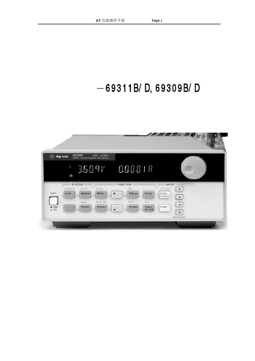
Agilent电源使用手册69311B/D,69309B/D一前面板显示栏说明的具体意义CV 输出或输出处于固定电压模式CC 输出1或输出2处于固定电流模式Unr 输出或输出不能进行调整Dis输出处于关闭状态按Output On/Off键使输出打开OCP 过电流保护为打开状态按OCP键使过电流保护状态关闭Proc 由于保护功能起作用显示输出已经被禁止按Prot Clear键来清除保护功能Shift Shift键已被按下Rmt 程序控制接口HP-IB,RS232处于工作状态按Local键使电源回到手动控制状态Addr 读写接口的地址口Err SCPI错误序列中出现一个错误按Error键来看错误代码SRQ 接口需要维修二前面板菜单的实际作用前面板控制菜单图示<1> System Keys蓝色无标签的按键就是Shift键起到按键功能转换的作用例如按shift键在显示栏上就显示Shift标示则按键上方标示的功能起作用如Error再次按Shift键则回到按键功能使电源从程序控制状态转换到手动控制状态如果电源已经处于LOCAL状态则local 按键无效ADDRESS <value> 设置HP-IB地址INTF <char> 选择通讯接口HP-IB,RS-232BAUDRATE <char> 选择波特率(300,600,1200,2400,4800,9600)PARITY <char> 消息奇偶性(NONE|EVEN|ODD|MARK|SPACE)FLOW <char> 流控制XON-XOFF|RTS-CTS|DTR-DSR|NONELANG <char> 选择语言(SPCI或COMP)REMOTE FT <char> HP14575A遥控面板的开关(ON/OFF)ROM <char> 固件版本号SN:<char> 电源序列号码按此键可以使直流电源进入以前保存的状态可以返回到前四个保存的状态0 到 3+(Shift + Channel) 输出1和输出2显示转换Display Measurement1<reading>V <reading>A Measures output channel 12<reading>V <reading>A Measures output channel 2 +(Shift + Error) 显示系统错误代码若没有错误显示0+Shift + Save保存目前电源的状态到固定存储器2Function Keys直流电源开状态和关状态的转换当关状态Dis显示在显示栏上+(Shift + Proc Clr) 保护环路复位使电源回到上一个程序状态+(Shift + OCP) 按此键在OCP起作用/不起作用之间切换如果OCP起作用则输出模式不能从定电压转到定电流模式并且OCP指示显示在显示栏中按,提出列表中的下一个命令按返回列表中的前一个命令Display Measurement<reading>V <reading>A 测量输出直流电压和电流<reading>V MAX 测量输出电压的峰值<reading>V MIN 测量输出电压的最小值<reading>V HIGH 测量电压脉冲的最高电平<reading>V LOW 测量电压脉冲的最低电平<reading>A MAX 测量输出电流的峰值<reading>A MIN 测量输出电流的最小值<reading>A HIGH 测量电流脉冲的最高电平<reading>A LOW 测量电流脉冲的最低电平<reading>A RMS 测量均方根值电流<reading>V DC:DVM 通过DVM输入测量直流电压<reading>V RMS:DVM 通过DVM输入测量均方根值电压+(Shift + Input)Display MeasurementCURR:RANGE<char> 选择电流范围AUTO|LOW|HIGHCURR:DET <char> 选择电流测量的带宽(ACDC|DC)TINT <char> 设置前面板测量的间隔15.6us to 1 seconds)POINTS <char> 设置前面板测量缓冲器的测量点数(1,2,4,8,32,64,128,256,512,1024,2048)按此键进入电压设置菜单Display Command Function1 VOLT <value> 设置输出1的电压2 VOLT <value> 设置输出2的电压HP66039B/66039D按此键进入电流设置菜单Display Command Function1 CURR <value> 设置输出1的电流2 CURR <value> 设置输出2的电流HP66039B/66039D按此键进入输出菜单设置列表Display Command Function*RST 设置直流电源回到出厂缺省值TYPE:CAP <char> 设置输出补偿(HIGH|LOW)PON:STATE <chat> 选择开电状态命令(RST|RCL0)PROT:DLY <value> 设置输出保护延迟时间(second)RI <char> 设置远距离约束模式DFI <char> 设置不连续故障指示状态(ON|OFF)DFT:SOUR <char> 选择DFI来源(QUES|OPER|ESB|RQS|OFF)PORT <char> 选择输出端口功能RIDFI/DIGIODIGIO <char> 设置读出I/O端口数0 through 7SENSE:PROT <char> 开环传感导线检测环路开关(ON|OFF)按此键显示保护状态Display Command FunctionOVER CURRENT 保护状态特征over currentNO FAULT 保护状态特征none tripped+(Shift + OV) 按此键进入过电压(overvoltage)保护菜单Display Command FunctionPROT:STAT <char> 打开或关闭过电压保护措施ON|OFF PROT:LEV <value> 设置过电压保护的保护值+(Shift + Cal) 按此键进入校准菜单<3> Entry Keys在特殊命令中的参数列表中进行上下选择增加或减小数值大小在闪光数字中进行左右移动按此键进入数字输入状态0 9 0到9是输入数字.是小数点- 是负号. , 例如输入33.58 按Enter Number,3,3,.,5,8,Enter (back space) 删除最后输入的数字+(Shift + Clear Entry) 按此键放弃输入的数值清除数值按此键执行输入的数值或使参数进入命令里。
Agilent B2900A 系列 精密电源 测量单元 数据手册说明书
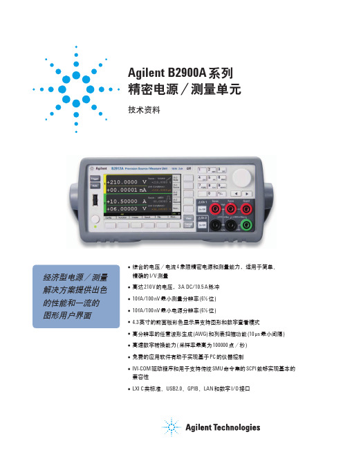
Agilent B2900A 系列精密电源/测量单元技术资料经济型电源/测量解决方案提供出色的性能和一流的图形用户界面●综合的电压/电流4 象限精密电源和测量能力,适用于简单、精确的I/V 测量●高达210 V 的电压,3 A DC/10.5 A 脉冲●10 fA/100 nV 最小测量分辨率(6½ 位)●10 fA/100 nV 最小电源分辨率(6½ 位)●4.3 英寸的前面板彩色显示屏支持图形和数字查看模式●高分辨率的任意波形生成(AWG) 和列表扫描功能(10 µs 最小间隔)●高速数字转换能力( 采样率最高为100000 点/秒)●免费的应用软件有助于实现基于PC 的仪器控制●IVI-COM 驱动程序和用于支持传统SMU 命令集的SCPI 能够实现基本的兼容性●LXI C 类标准、USB2.0、GPIB、LAN 和数字I/O 接口Agilent B2900A 系列精密电源/测量单元是外观紧凑、成本经济的台式电源/测量单元(SMU),能够同时输出并测量电压和电流。
SMU 在单个仪器中整合了电流源、电压源、电流表、电压表以及在这些功能之间自由切换的能力。
Agilent B2900A 系列SMU 以前所未有的低价格提供一流的性能。
它拥有广泛的电压(210 V) 和电流(3 A 直流和10.5 A 脉冲) 电源能力,卓越的精度( 低至10 fA/100 nV 的电源和测量分辨率) 和高测量吞吐率。
它还支持任意波形生成功能。
此外,Agilent B2900A 系列具备出色的图形用户界面及各种查看模式,可显著改进测试生产率、调试和表征过程。
Agilent B2900 系列SMU 凭借其全面、综合的电源和测量能力,成为测试半导体、有源/无源器件以及各种其他器件与材料的理想选择。
B2900 系列广泛应用在用于工业开发、测试和制造业等领域的研发和教育应用。
它们还可作为独立仪器或系统元器件使用。
安立8000a综测仪技术参数
安立8000a综测仪技术参数1.引言1.1 概述安立8000a综测仪是一种高精度的测试仪器,用于测量电力系统的各种参数和性能。
它具有广泛的应用领域,包括电力传输和配电系统、工业生产线、发电厂等。
该仪器采用了先进的技术和设计,能够准确地测量电流、电压、功率因数、频率等多种电力参数。
安立8000a综测仪具有多种功能,包括实时显示、数据记录、数据分析等。
它能够实时地监测电力系统的运行状态,及时发现并解决问题。
同时,该仪器还能够记录电力系统的工作数据,并进行分析,从而帮助用户了解系统的性能和运行情况。
该综测仪的技术参数非常出色。
首先,它具有高精度的测量能力,能够实现对电力参数的精确测量,保证了数据的准确性。
其次,它具有快速响应的特点,能够在瞬态和暂态过程中进行准确的测量。
此外,安立8000a综测仪还具有灵活的配置和操作界面,用户可以根据自己的需求选择合适的配置,并通过直观友好的操作界面轻松地进行操作。
同时,该仪器还提供了丰富的数据通信接口,便于与其他设备进行联接,实现数据的共享和传输。
总之,安立8000a综测仪是一款功能强大、性能优越的测试仪器,能够满足电力系统各个方面的测量需求。
它的高精度、快速响应和灵活配置使其成为电力系统测试领域的重要工具。
在未来,我们可以期待这种测试仪器在电力行业中的更广泛应用,为电力系统的稳定运行和优化改进提供有力的支持。
1.2文章结构文章结构部分主要用来说明整个文章的组织架构和各个部分的内容安排,以便读者能够对文章的内容有一个全面的了解。
在本篇文章中,文章结构部分的主要内容可以按照以下方式展开:文章结构部分的内容可以参考如下所示:1.2 文章结构本篇文章将围绕安立8000a综测仪的技术参数展开,旨在全面介绍该仪器的技术规格和性能特点。
具体而言,本文分为以下几个部分:2.1 技术参数一在这一部分,我们将详细介绍安立8000a综测仪的第一个技术参数。
通过对该参数的解析和分析,读者将能够了解到该仪器在某个方面的性能表现和应用场景。
AgiIent推出具有高档电源特性的低成本直流电源
AgiIent推出具有高档电源特性的低成本直流电源
佚名
【期刊名称】《国外电子测量技术》
【年(卷),期】2008(27)8
【摘要】安捷伦科技(NYSE:A)今大推出U8000系列单路输出不可编程直流电源,这是最畅销的Agilent E3600系列的低成本扩展。
除了节约成本以外,这些电源还捉供通常只有高档可编程电源才具备的诸多特性,因此具有极高的价值。
它们的功率范围是90W至150W,非常适合再种电子制造应用,也为教学应用提供了可靠和低成本的优质电源。
【总页数】1页(P84-84)
【关键词】直流电源;电源特性;可编程电源;安捷伦科技;节约成本;功率范围
【正文语种】中文
【中图分类】TN86;TP332
【相关文献】
1.具有高档电源特性的低成本直流电源 [J],
2.适合便携式数字视频应用的达芬奇处理器具有低成本与双电源模式等优化特性[J],
3.Agilent推出具有高档电源特性的低成本直流电源 [J],
4.安捷伦科技推出具有高档电源特性的低成本直流电源 [J],
5.Agilent推出具有高档电源特性的低成本直流电源 [J],
因版权原因,仅展示原文概要,查看原文内容请购买。
- 1、下载文档前请自行甄别文档内容的完整性,平台不提供额外的编辑、内容补充、找答案等附加服务。
- 2、"仅部分预览"的文档,不可在线预览部分如存在完整性等问题,可反馈申请退款(可完整预览的文档不适用该条件!)。
- 3、如文档侵犯您的权益,请联系客服反馈,我们会尽快为您处理(人工客服工作时间:9:00-18:30)。
AgilentU8000A系列单路输出直流电源技术资料更多保护,更方便 — 更便宜找到完全适合您测试要求和预算的电源往往很难。
无论您是制造消费类电子产品,测试电子元件,还是寻找可靠而价廉的电源,现在,Agilent 基本电源家族又增添了单路输出,功率范围为90 W 至150 W 的不可编程电源供您选择。
它们具有通常可编程电源才具备的能力,以极高的效率为您提供极高的价值。
您能获得最短的设置时间,最少的测量错误和最高的设备可靠性。
这些优质电源与众不同 —它们经过严格的安全认证和遵从Agilent 质量标准 — 并且价格适中。
Agilent U8000A 系列是90 W 至150 W 的单路输出不可编程电源,它们具有通常只有可编程电源才具备的性能特性。
U8000A 系列有极高的价值,它们提供可靠的直流功率,有效的设置能力和重要的安全特性,因此您可将其用于电子制造和教学等各类应用。
符合您应用要求的电源U80000系列具有90 W 至150 W 功率范围,适合计算机和外设,通信系统和外设,航天/航空系统,电子元件等各种电子制造应用。
U8000系列与Agilent E3600直流电源家族一起为您提供更宽的电源功率范围。
主要特性杰出的负载调整率和电源调整率:(CV: < 0.01% + 2 mV;CC: < 0.02% + 2 mA)低输出噪声:1 mVrms (20 Hz 至20 MHz)过压和过流保护具有背光能力的LCD 显示为安全提供的等待输出保存和调用功能,达三种存储器状态安全特性: 键位锁定和机械锁结构图1. U8001A 90 W 和U8002A 150 W 单路输出直流电源2更好的功能特性和更高的性能指标实现更有效的工作—一切均在预算之内通常只有可编程电源才具备的与众不同特性U8000系列为保护被测装置(DUT)免受损坏提供完全集成的过压保护(OVP)和过流保护(OCP)。
使用可保存和调用三种存储器状态的能力,就可把测量错误和设置时间减到最少。
U8000系列还提供各种安全特性,如用键位锁防止因偶尔触及前面板造成的测量错误。
在激活键位锁时,除键位锁按键外,前面板上的旋钮和所有按键都失去作用。
电源后面板上的机械锁保护仪器不会遗失。
LCD显示可选择背光灯开/关,从而为观察数据提供更明亮的显示(见图2)。
具有本档次仪器中坚实可靠的性能U8000系列有优异的负载调整率和电源调整率(恒压,CV: <0.01%+2mV;恒流,CC: <0.02%+2mA),以保证即使负载改变时也能得到稳定的输出。
50µs的快跳变时间显著减少了测试时间,从而也降低了制造成本。
U8000系列20Hz至20MHz有1mVrms和3mArms的低输出噪声,这样纯净的输出也把DUT中的干扰减到最小。
得到更高的安全性U8000系列经过各种工业安全标准的严格测试: CSA(美国和加拿大强制要求),C-tick(澳大利亚)和CE(欧洲)。
为防止损坏DUT,U8000系列有完全集成的OVP和OCP。
安全特性可避免测量错误和保证电源的安全存储。
键位锁能力防止对前面板的偶尔触及,后面板机械锁保证仪器的安全储存。
前面板操作您可通过易于使用的旋钮和按键以要求的分辨率轻松地设置输出。
在前面板上以10mV/10mA的最高分辨率设置电压和电流。
此外,您还可保存和调用储存在内部非易失存储器中的三种工作状态。
易于使用的控制功能:●启用和禁用OVP和OCP●设置OVP和OCP门限电平●清除OVP和OCP条件●设置和显示电压和电流极限值●工作状态保存/调用●把电源复位到开机状态●校准电源●启用或禁用输出图2. LCD显示背光灯开/关选择图3. U8000A 系列单路输出直流电源的安全特性Backlight ON Backlight OFFCompliant to several safetystandards-CSA, C-tick, CEPhysical lock3U8000系列性能特性选择调节电压和电流的旋钮控制功能完全集成的过压和过流保护,以防止损坏 DUT三个保存用户定义工作状态的位置(M1, M2, M3),具有保存和调用能力设置和显示电压及电流极限值清晰可见的LCD显示电表模式的实际输出电压和电流值,以及极限模式的极限电压和电流值用旋钮实现对电压和电流快速和类似模拟方式的控制实现更明亮数据显示的背光灯开/关选择通用接线柱提供使用安全测试线,香蕉插头或脱头导线的灵活性防止偶尔触及前面板的键位锁定/解锁选择电源输出的启用和禁用控制4性能特性1 为一小时预热后的指标补充特性补充特性参数U8001AU8002A温度系数 (12个月)CV: < 100 ppm/°CCC: < 380 ppm/°CCC: < 300 ppm/°C输出电压过冲(开机和关机期间, 输出控制设置到小于1 V )<1 V 电压编程速度, 至总行程的1%以内向上满载150 ms空载100 ms向下满载30 ms空载450 ms调用上一次的设置有过压保护响应时间 < 1.5 ms, 门限电压等于或大于3 V; < 10 ms, 门限电压小于3 V(在OVP 条件产生后, 从输出电压的90%降到1 V 的平均时间)保护特性参数U8001AU8002A过压保护精度 ± (%输出+偏置)< 0.5% + 0.5 V 过压保护编程范围1 V 至33 V 过流保护精度 ± (% 输出+偏置)< 0.5% + 0.5 A过流保护编程范围1 A 至3.3 A1 A 至5.5 A 交流电网输入特性参数U8001A U8002A选件100: 90至110 Vac, 47至63 Hz 输入电源选件 (可选择)选件120: 104至127 Vac, 47至63 Hz 选件220: 194至237 Vac, 47至63 Hz 选件240: 207至253 Vac, 47至63 Hz保险丝外部,用户装入机械结构指标参数U8001A U8002A外形尺寸 (W x H x L)88.1 mm x 212.3 mm x 394.3 mm 重量 (kg)7.3 kg 8.3 kg电气指标参数U8001A U8002A 额定输出 (0°C 至40°C)0 至 + 30 V 0 至 + 30 V 0至3 A0至5 A电源调整率和负载调整率CV: < 0.01% + 2 mV CC: < 0.02% + 2 mA 纹波和噪声 (25°C ± 5°C)CV: 12 mVp-p, < 1 mVrms;CC: 3 mArms 负载瞬态响应时间 (从满载到半载或从半载到满载, 15 mV 以内)< 50 µs 编程精度1 (25°C ± 5°C)< 0.35% + 20 mV < 0.35% + 20 mA 读回精度1 (25°C ± 5°C)< 0.35% + 20 mV < 0.35% + 20 mA 电表分辨率电压: 10 mV 电流: 10 mA 最大浮地输出电压± 240 Vdc5Agilent Open 简化连接和编程测试系统的过程, 以帮助工程师设计、验证和制造电子产品。
Agilent 的众多系统就绪仪器, 开放工业软件, PC 标准 I/O 和全球支持, 将加速测试系统的开发。
要了解更详细的情况, 请访问:/find/openconnect 。
/find/agilentdirect 高置信地快速选择和使用您的测试设备解决方案/find/emailupdates 得到您所选择的产品和应用的最新信息。
欢迎订阅免费的本文中的产品指标和说明可不经通知而更改 Agilent Technologies, Inc. 2008出版号:5989-7281CHCN 校 稿:祁 萌2008年6月 印于北京请通过Internet 、电话、传真得到测试和测量帮助。
在线帮助:/find/assist 热线电话:800-810-0189热线传真:800-820-2816安捷伦科技有限公司总部地址:北京市朝阳区望京北路3号电话:800-810-0189(010) 64397888传真:(010) 64390278邮编:100102上海分公司地址:上海市西藏中路268号来福士广场办公楼7层电话:(021) 23017688传真:(021) 63403229邮编:200001广州分公司地址:广州市天河北路233号中信广场66层07-08室电话:(020) 86685500传真:(020) 86695074邮编:510613成都分公司地址:成都市下南大街6号天府绿洲大厦0908-0912室电话:(028) 86165500传真:(028) 86165501邮编:610012深圳分公司地址:深圳市高新区南区黎明网络大厦3楼东区电话:(0755) 82465500传真:(0755) 82460880邮编:518057西安办事处地址:西安市高新区科技路33号高新国际商务中心数码大厦23层01-02室电话:(029) 88337030传真:(029) 88337039邮编:710075安捷伦科技香港有限公司地址:香港太古城英皇道1111号太古城中心1座24楼电话:(852) 31977777传真:(852) 25069256E-mail: tm_asia@香港热线:800-938-693香港传真:(852) 25069233有关安捷伦开放实验室暨测量方案中心和安捷伦测试与测量技术认证,请访问: /find/openlab安捷伦电子测量事业部中文资料库: /chcn/LXI 是GPIB 的LAN 基继承者,提供更快和更有效的连通能力。
安捷伦是 LXI 联盟的发起成员。
安捷伦承诺经我们维修和校准的设备在返回您时就像新设备一样。
安捷伦设备在整个生命期中都保持其全部价值。
您的设备将由接受过安捷伦专业培训的技术人员,使用全新的工厂校准规范,自动维修诊断步骤和正品备件进行维修和校准。
您可对您的测量充满信心。
安捷伦还为您的设备提供各种测试和测量服务,包括入门级培训、现场培训,以及系统集成和项目管理。
要了解有关维修和校准服务的详细情况,请访问:/find/removealldoubt。
