PCB布线设计(之五)MicroChip_
MICROCHIP dsPIC 语言工具库 说明书

DS51456B_CN 第 ii 页
2005 Microchip Technology Inc.
dsPIC® 语言工具库 目录
前言 ................................................................................................................................. 1 第 1 章 库的概述
第 3 章 dsPIC 外设函数库
3.1 简介 .............................................................................................................. 73 3.2 使用 dsPIC 外设函数库 ................................................................................. 74 3.3 外部 LCD 函数 .............................................................................................. 74 3.4 CAN 函数 ...................................................................................................... 81 3.5 ADC12 函数 .................................................................................................. 95 3.6 ADC10 函数 ................................................................................................ 102 3.7 定时器函数 ................................................................................................. 109 3.8 复位 / 控制函数 ........................................................................................... 117 3.9 I/O 端口函数 ............................................................................................... 120 3.10 输入捕捉函数 ............................................................................................ 125 3.11 输出比较函数 ............................................................................................ 131 3.12 UART 函数 ................................................................................................ 141 3.13 DCI 函数 ................................................................................................... 150 3.14 SPI 函数 .................................................................................................... 158 3.15 QEI 函数 ................................................................................................... 166 3.16 PWM 函数 ................................................................................................. 171 3.17 I2C 函数 .................................................................................................... 183
microchip 命名规则
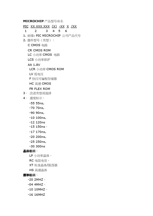
MICROCHIP产品型号命名PIC XX XXX XXX (X) -XX X /XX1 2 3 4 5 61. 前缀: PIC MICROCHIP 公司产品代号2. 器件型号(类型):C CMOS 电路CR CMOS ROMLC 小功率CMOS 电路LCS 小功率保护AA 1.8VLCR 小功率CMOS ROMLV 低电压F 快闪可编程存储器HC 高速CMOSFR FLEX ROM3.改进类型或选择4.速度标示:-55 55ns,-70 70ns,-90 90ns,-10 100ns,-12 120ns-15 150ns,-17 170ns,-20 200ns,-25 250ns,-30 300ns晶体标示:LP 小功率晶体,RC 电阻电容,XT 标准晶体/振荡器HS 高速晶体频率标示:-20 2MHZ,-04 4MHZ,-10 10MHZ,-16 16MHZ-20 20MHZ,-25 25MHZ,-33 33MHZ5.温度范围:空白0℃至70℃,I -45℃至85℃,E -40℃至125℃6.封装形式:L PLCC 封装JW 陶瓷熔封双列直插,有窗口P 塑料双列直插 DIP-8PQ 塑料四面引线扁平封装W 大圆片SL 14 腿微型封装-150milJN 陶瓷熔封双列直插,无窗口SM 8 腿微型封装-207milSN 8 腿微型封装-150 milVS 超微型封装8mm×13.4mmSO 微型封装-300 milST 薄型缩小的微型封装-4.4mmSP 横向缩小型塑料双列直插CL 68 腿陶瓷四面引线,带窗口SS 缩小型微型封装PT 薄型四面引线扁平封装TS 薄型微型封装8mm×20mmTQ 薄型四面引线扁平封装。
PCB设计-Microchip
PCB布线设计(一)Microchip公司/BonnieC.Baker在当今激烈竞争的电池供电市场中,由于成本指标限制,设计人员常常使用双面板。
尽管多层板(4层、6层及8层)方案在尺寸、噪声和性能方面具有明显优势,成本压力却促使工程师们重新考虑其布线策略,采用双面板。
在本文中,我们将讨论自动布线功能的正确使用和错误使用,有无地平面时电流回路的设计策略,以及对双面板元件布局的建议。
自动布线的优缺点以及模拟电路布线的注意事项设计PCB时,往往很想使用自动布线。
通常,纯数字的电路板(尤其信号电平比较低,电路密度比较小时)采用自动布线是没有问题的。
但是,在设计模拟、混合信号或高速电路板时,如果采用布线软件的自动布线工具,可能会出现一些问题,甚至很可能带来严重的电路性能问题。
例如,图1中显示了一个采用自动布线设计的双面板的顶层。
此双面板的底层如图2所示,这些布线层的电路原理图如图3a和图3b所示。
设计此混合信号电路板时,经仔细考虑,将器件手工放在板上,以便将数字和模拟器件分开放置。
采用这种布线方案时,有几个方面需要注意,但最麻烦的是接地。
如果在顶层布地线,则顶层的器件都通过走线接地。
器件还在底层接地,顶层和底层的地线通过电路板最右侧的过孔连接。
当检查这种布线策略时,首先发现的弊端是存在多个地环路。
另外,还会发现底层的地线返回路径被水平信号线隔断了。
这种接地方案的可取之处是,模拟器件(12位A/D转换器MCP3202和2.5V参考电压源MCP4125)放在电路板的最右侧,这种布局确保了这些模拟芯片下面不会有数字地信号经过。
图3a和图3b所示电路的手工布线如图4、图5所示。
在手工布线时,为确保正确实现电路,需要遵循一些通用的设计准则:尽量采用地平面作为电流回路;将模拟地平面和数字地平面分开;如果地平面被信号走线隔断,为降低对地电流回路的干扰,应使信号走线与地平面垂直;模拟电路尽量靠近电路板边缘放置,数字电路尽量靠近电源连接端放置,这样做可以降低由数字开关引起的di/dt效应。
microchip数字电源方案

microchip数字电源方案数字电源方案(Microchip)摘要:本文介绍了Microchip的数字电源方案,包括其基本原理、设计特点以及应用优势。
通过对Microchip数字电源方案的深入了解,读者可以更好地理解并应用该方案。
第一节:引言数字电源方案是现代电子设备中不可或缺的组成部分,其作用包括对电流、电压等进行准确控制,并满足各种设备对电能的需求。
Microchip的数字电源方案基于先进的技术和创新的设计,为用户提供了高度可靠和灵活的电源解决方案。
第二节:基本原理Microchip的数字电源方案基于数字信号处理和控制技术,利用数字控制芯片对电源进行精准的调节和监测。
它通过采集电源输入和输出的相关参数,如电流、电压等,以数字信号的形式进行处理和传输。
通过对电源的高效控制和管理,数字电源方案能够提供更加稳定和可靠的电源输出。
第三节:设计特点1. 高度集成化:Microchip的数字电源方案集成了多种功率器件和控制电路,通过高度集成化的设计,能够在较小的尺寸下提供较高的功率输出。
2. 高精度控制:数字电源方案采用先进的控制算法和实时反馈机制,能够实现对电源电压和电流的高精度控制,以满足各种应用对电源的稳定性要求。
3. 强大的保护功能:数字电源方案具备多种保护功能,包括过压保护、过流保护、短路保护等,可以有效地保护设备和电源免受异常工作状态的影响。
4. 可编程性:通过软件编程,用户可以对数字电源方案进行灵活的配置和调节,以适应不同的应用需求。
同时,数字电源方案支持实时监测和远程控制,方便用户对电源状态进行实时监管和管理。
第四节:应用优势1. 工业自动化:数字电源方案在工业自动化领域具有广泛的应用,可以用于运动控制、机器人技术、工艺控制等各种场景,实现对设备的高效供电和精准控制。
2. 通信设备:在通信设备中,数字电源方案能够提供稳定和可靠的电源输出,保证设备的正常运行。
同时,数字电源方案支持高效能耗管理,通过智能控制降低设备的功耗,延长设备的使用寿命。
Microchip高速和超高速USB集线器设计
FS眼图
电压
其他终端
LS眼图
© 2014 Microchip Technology Incorporated. All Rights Reserved.
C15L01 USB
Slide
18
协议
USB的世界包罗万象,有许多不同的协议可供选择 USB1.1引入了USB FS/LS 全速和低速 USB2.0引入了USB HS 高速 HSIC USB3.0引入了USB SS 超高速 USB BC1.2
© 2014 Microchip Technology Incorporated. All Rights Reserved.
在通信挂起后主机若想唤醒设备,可将数据线上信号的极性翻 转至少20 ms。
具 有 远 程 唤 醒 功 能 集 的 设 备 还 可 以 自 行 发 起 恢 复 ( 15 ms Kstate) 一旦恢复.…端口返回 “已使能”状态
© 2014 Microchip Technology Incorporated. All Rights Reserved.
C15L01 USB
Slide
3
定义
机为其分配一个地址并使能它。此时,可认为设备已配置
上行端口 —— USB集线器上面向USB主机的端口 下行端口 —— USB集线器上面向USB设备的端口 自供电 —— 由直接连接至USB设备或集线器的电源供电 总线供电 —— 由USB连接器的 VBUS引脚供电 已配置/未配置 —— 初次连接时USB设备未配置,直至主
MultiTRAK
Upstream PHY
Speed Key: 480 Mbps Path 12 Mbps Path
Microchip集成并简化PIC24F单片机的图形功能,具备高达96 KB的RAM

具 备 高 达 9 6KB的 R M A
全 球领 先 的整 合 单 片 机 、模 拟器 件 和 闪存 专 利 解 决 方 案 的 供 应 商 一 co hpT c n lg c Mi c i e h oo yI . r n
( 国 微 芯 科 技 公 司 ) 日 前 宣 布 , 推 出 8款 美 PC 4 J5 DA 单片 机 系 列 器件 。该系 列器 件 集 成 I2F26 了 3个 图形 加 速 单 元 和 1 显示 控 制 器 , 个 以及 9 6 K 的 R M 。这 种 集 成 因不 需 要 外 部 R M 和 现 B A A
-
电 子 工 业 专 用 殳 备
f rEl c r p cPr d cs o eto A o u t
・
企业之窗 ・
形库 , 它提供完 整 的源代 码 , 持多种 字体和 语言 , 支 并
包含 许多预制 的图形对象 。与这个 形库相辅相成 的 是免费的 图形显示设计 师软件 , 可以通 过一 个可视 它 化 向导 帮助 首次使用 的用户进行用户界 面设计 。该 图 形库还具备 为电容式触 摸板和滑动条及 电阻式触摸屏 预 配 置 的界 面 。这 两 款 l 具 都 与 Mi o hp免 费 的 丁 c ci r MP AB集成 开发 环境完全兼 容,川户现在就 可 以在 L
p
:
: 譬c ●
l H :I : l I E
j i 譬}
{
^
}
mI i y
I 鞫 蹬 ^ l - 讲 :。 ’ 一
{ } 囊
实验课程 一使嵌入 式应用设计 更容 易具备 时尚的 图
形界面 。该半 台包括 Mi o hp免费 的性能优化的图 c ci r
Microchip推出同步升压稳压器
Microchip 推出同步升压稳压器
Microchip 推出同步升压稳压器,延长电池应用寿命
Microchip Technology Inc.(美国微芯科技公司)今天宣布推出MCP1640 同步升压稳压器,它具有低至0.35V 的工作电压,静态电流低至19 微安,关断电流不到1 微安。
500 kHz 的MCP1640 稳压器具备两个集成的FET 晶体管,输出电流高达350 毫安,使消费电子市场中的电池供电应用(如电动剃须刀、牙刷、GPS 设备和便携式音乐播放器)尺寸更加小巧,电池寿命更长。
MCP1640 稳压器的工作电压低至0.35V,启动电压为0.65V,即使是
电力耗尽的单节碱性、镍氢或镍镉电池也能将其启动运行。
PWM/PFM 选项
可实现器件的低静态电流和关断电流,并实现高达96%的效率,延长了电池
的使用时间。
该稳压器的两个集成式FET 晶体管减少了元件数量,使整体设
计更为小巧。
Microchip 模拟和接口产品部副总裁Bryan Liddiard 表示:“MCP1640满足了用户在应用中减少所需电池数量的需要,同时延长了电池使用时间并
使设计更为紧凑。
”
Microchip 模拟和接口产品部高级产品营销工程师Mikhail Voroniouk 补充道:“MCP1640升压稳压器秉承了Microchip 在低功耗产品方面的优势,进一步补充了我们的超低功耗PIC®单片机产品线,尤其是必须使用单节
电池供电的应用。
”。
Microchip 电机控制设计解决方案
Microchip电机控制设计解决方案
邓永梁
Microchip代理商技术支持资源经理
为何选择Microchip作为您下一
个电机控制设计解决方案?我们
的8位单片机和16位数字信号控
制器包含专为电机控制而设计的
创新型片上外设。
使用6至144
引脚的电机控制器件,我们可为
每个应用提供完美的解决方案。
时间紧迫?我们针对大多数电机
控制算法,提供免费的电机控制
软件、应用笔记和原理图,以缩短您的开发周期。
我们的低成本开发工具,专门用于电机控制,以促进定制应用的快速原型开发。
我们还提供技术培训课程和网上研讨会,使工程师快速熟悉我们的器件和最新的电机控制算法。
6引脚PIC10F产品使电机控制设计人员有机会在成本或空间受限的应用中使用单片机。
有些PIC16F系列具有一个或
多个增强型捕捉/比较/PWM
外设(ECCP),用于BLDC
电机换相或步进电机控制。
有些PIC18器件包含用于三
相电机应用的三相电机控制
PWM外设和正交编码器接口
(QEI)。
高级电机控制可受益于
dsPIC®数字信号控制器(DSC)
中的DSP资源。
例如,我们
的无传感器磁场定向控制算法,利用带有数据饱和的单周期乘累加(MAC)、零开销循环及桶型移位,能够实现极佳的性能。
MTD6501/2 为三相BLDC风扇驱动器提供简单的设计,无需外部调节。
步进电机驱动器MTS2916A/62C19A,支持驱动2个有刷直流电机,适用于安防摄像头和打印机应用。
完整的产品解决方案。
microchip数字电源方案

microchip数字电源方案数字电源方案是指利用数字技术控制和管理电源供应的系统。
它使用集成电路和控制算法来实现高效、可靠的电源管理,具有快速响应、精确控制和低功耗的特点。
Microchip是全球领先的半导体技术公司,为各种应用领域提供创新的数字电源解决方案。
一、微控制器和DSPMicrochip的数字电源方案主要基于微控制器和数字信号处理器(DSP)技术。
微控制器是一种集成了处理器核心、存储器、输入输出接口和定时器等功能的单芯片系统,适用于各种电源管理应用。
DSP 则特别适用于高性能的数字信号处理和控制应用,可以实现复杂的算法和实时控制。
二、数字功率控制Microchip的数字电源方案包括了数字功率控制技术。
通过使用先进的数字控制算法,可以实现对功率变换器的精确控制。
这种技术可以实现功率因数校正、电压和电流调节等功能,提高电源效率并降低能源消耗。
三、数字电源管理Microchip的数字电源方案还包括了数字电源管理功能。
这些功能包括电源监测、故障保护和故障诊断等功能,可以提高电源系统的可靠性和稳定性。
通过数字电源管理,可以实现远程监控和控制,提高系统的可维护性。
四、数字电源设计工具为了帮助开发人员设计和优化数字电源方案,Microchip提供了丰富的数字电源设计工具。
这些工具包括仿真软件、开发板和参考设计等,可以帮助开发人员快速搭建并验证数字电源系统的性能。
五、应用领域Microchip的数字电源方案适用于各种应用领域。
例如,工业自动化中的电源管理、通信设备中的高效电源供应、电动汽车中的电池管理等。
数字电源方案可以提高系统的能效,减少能源消耗,并提高系统的稳定性和可靠性。
结论Microchip的数字电源方案是一种先进的电源管理解决方案,利用最新的数字技术和算法来实现高效、可靠的电源供应。
它能够提高电源系统的效率和稳定性,并减少能源消耗。
通过使用Microchip的数字电源方案,开发人员可以快速设计和实现各种应用领域的数字电源系统。
微芯片(Microchip)模块选择指南:分析类和接口产品说明书

Spring 2011Analog and Interface Product Selector Guide⏹ Thermal Management ⏹Battery Management ⏹Interface Peripherals⏹ Power Management ⏹Linear & Mixed-Signal ⏹Safety & Security/analogTable of Contents2 Analog and Interface Product Selector GuideThermal ManagementTemperature Sensors ............................................4Logic Output Temperature Sensors ....................4Voltage Output Temperature Sensors .................4Serial Output Temperataure Sensors .................4Brushless DC Fan Controllers andFan Fault Detectors (5)Motor DriversStepper Motors, DC Motors and 3 PhaseBLDC Fan Controllers (5)Power ManagementVoltage References ...............................................6Linear Regulators50-250 mA LDO Linear Regulators ....................6300 mA LDO Linear Regulators .........................7500-800 mA LDO Linear Regulators ..................71A and > LDO Linear Regulators .......................8Application Specific LDO Linear Regulators ........8Combination Products ...........................................8Switching Regulators .............................................9PWM Controllers ...................................................9Charge Pump DC-to-DC Converters .......................10Inverting or Doubling Charge Pumps ................10Inverting and Doubling Charge Pumps .............10Regulated Charge Pumps ................................10CPU/System Supervisors ....................................11Voltage Detectors ................................................12Power MOSFET Drivers ........................................12Low-Side Drivers, 0.5A to 1.2A PeakOutput Current ...............................................12Low-Side Drivers, 1.5A Peak Output Current .....12Low-Side Drivers, 2.0A to 12.0A PeakOutput Current ...............................................13High-Side/Low-Side Drivers .............................13Synchronous Buck High-Side Drivers ................13Battery Chargers .................................................14Hot Swap Controllers . (15)LinearOp Amps ............................................................15High Precision Operational Amplifiers ...................18Chopper Stabilized .........................................18Auto-Zero .......................................................18Programmable Gain Amplifiers (PGA) ....................18Selectable Gain Amplifiers (SGA) ..........................18Comparators . (19)Mixed SignalSuccessive Approximation Register (SAR)A/D Converters ...................................................19Delta-Sigma A/D Converters ................................20Energy Measurement IC’s ....................................20Dual-Slope A/D Converters ..................................20Binary and BCD A/D Converters ...........................21Display A/D Converters .......................................21Digital Potentiometers .........................................21Frequency-to-Voltage/Voltage-to-FrequencyConverters ..........................................................23D/A Converters (23)InterfaceController Area Network (CAN) Products (24)Infrared Products.................................................24Ethernet Products ...............................................24Passive Access Products .....................................24LIN Transceiver Products ......................................25Serial Peripherals ................................................25IEEE 802.15.4 ZigBee® RF Tranceiver Products .....25Stand-alone RF Receiver Products ........................25USB Products .. (25)Safety & SecurityPhotoelectric Smoke Detector ICs ........................26Ionization Smoke Detector ICs .............................26Ionization Smoke Detector Front Ends ..................26Piezoelectric Horn Drivers (26)Analog Design and Development ToolsThermal Management ..........................................27Mixed Signal .......................................................27Power Management .............................................28Interface .............................................................29Linear .................................................................30Analog Blank Evaluation Boards ...........................30Miscellaneous Analog Demonstrationand Evaluation Tools (30)Featured Analog Development ToolsThermal Management ..........................................31Mixed Signal .......................................................31Power Management .............................................31Interface .............................................................32Linear .. (32)Part Number DesignationsAnalog Products with “TC” Prefix ..........................33Analog Products with “MCP” Prefix .......................34Analog Products with “RE46C” Prefix .. (35)Need Additional Support and Resources?Microchip is committed to supporting its customers byhelping design engineers develop products faster and more efficiently. Customers can access three main service areas at . The Support area provides a fast way to get questions answered. The Sample area offers evaluation samples of any Microchip device. microchipDIRECT provides 24-hour pricing, ordering, inventory and credit for convenient purchasing of all Microchip devices and development tools. This site also features online programming capabilities. Finally, the Training area offers opportunities to expand your knowledge with Microchip’s online web seminars and hands-on courses at our worldwide Regional Training Centers (RTCs). Our seminars and training classes are designed to fit your schedule and offer an overview of many product, development tool and application topics. Visit /training for class content and schedules.Have you ever encountered a technical dilemma at a critical point in your design development and your supplier was not available to answer your questions? Microchip’s first ever 24/7 global technical support line brings technical support resources any time help is needed. Because some technical problems require hands-on assistance in order to be resolved quickly, Microchip has also developed a global team of field applications engineers and field sales engineers for local assistance.Microchip’s integrated analog technology, peripherals and features are engineered to meet today’s demanding designrequirements. Our broad spectrum of analog products addresses thermalmanagement, power management, battery management, mixed-signal, linear, interface and safety & security solutions. Combined with “Intelligent Analog” microcontrollers, Microchip offers an extensive analog portfolio for thousands of high-performance design applications in the automotive, communications (wireless), consumer, computing and industrial control markets.Our broad portfolio of stand-alone analog and interface devices offershighly integrated solutions that combine various analog functions in space-savingpackages and support a variety of bus interfaces. Many of these devices support functionality that enhances theanalog features currently available on PIC®microcontrollers.Want a Business Partner,Not Just a Vendor?Successful companies recognize the value of a strategic supplier relationship to help them deliver innovative products to their markets in a timely manner. They trust their suppliers to furnish quality components for current design opportunities as well as provide technology road maps and innovative solutions to stay ahead of tomorrow’s design trends.Microchip Technology provides low-risk product development, lower total system cost and faster time to market to more than 45,000 of these successful companies worldwide. Headquartered in Chandler, Arizona, Microchip offersoutstanding technical support along with dependable delivery and quality.Founded in 1989, Microchip’s business model is based on a series of guiding values that aim to establish successful customer partnerships by exceeding expectations forproducts, services and attitude. Continuous improvement, technology innovation and the pursuit of the highest quality possible drive Microchip’s company culture.The result is a worldwide organization dedicated to delivering whole product solutions which include high performance silicon devices, easy-to-use development tools, outstanding technical support and sophisticated technical documentation.Are Quality and Delivery a Concern?Microchip’s quality systems are certified according to the International Organization for Standards/Technical Specification (ISO/TS)-16949:2002 requirements. This demonstrates that the Company’s quality systems meet the most stringent industry quality-management system standards, resulting in high-quality semiconductor products.Direct control over manufacturing resources allows shortened design and production cycles. By owning the wafer fabrication facilities and the majority of the test and assemblyoperations, and by employing proprietary statistical process control techniques, Microchip has been able to achieve and maintain high production yields.Are you Looking for CompleteAnalog & Interface Design Solutions?Microchip Technology’s Stand-Alone Analog & Interface PortfolioAnalog and Interface Product Selector Guide 328Analog and Interface Product Selector GuideAnalog and Interface Product Selector Guide 2930 Analog and Interface Product Selector GuideThermal Management ProductsMCP9700 Thermistor Demo Board (MCP9700DM-TH1)The MCP9700 Thermistor Demo Board contains the analog circuitry to measure temperature. The board uses BC Components’ 232264055103 NTC thermistor to convert temperature toresistance. The thermistor is placed in a voltage divider which converts resistance to voltage. This voltage is filtered and placed at the MCP6S22Programmable Gain Amplifier’s (PGA) CH0 input. The PGA gains and buffers the thermistor.PT100 RTD Evaluation Board (TMPSNS-RTD1)This board demonstrates how to bias a Resistive Temperature Detector (RTD) and accurately measure temperature. Up to two RTDs can be connected. The RTDs are biased using constant currentsource and the output voltage is scaled using a differential amplifier. The output is then connected to a 12-bitdifferential Analog-to-Digital Converter (ADC) MCP3301. The ADC outputs serial data to a PIC18F2550 device using a Serial Peripheral Interface (SPI). The data is transmitted to a PC using a USB interface. A Microsoft Excel® macro is used as a Graphical User Interface (GUI) to acquire the data. The acquired data is stored in an Excel worksheet and graphed as a real-time strip chart display.MCP9800 Temperature Data Logger Demo Board(MCP9800DM-DL)Allows users to store up to 128,000 temperature readings from the MCP9800 sensor to the 24LC1025, Microchip’s 1024 Kbit EEPROM. A PIC16F684 MCU communicates with the sensorand EEPROM. In addition, the PIC MCU interfaces to a PC using the PICkit™ 1 Flash Starter Kit and transfers thetemperature readings from the EEPROM to the PC. Microsoft Excel® can be used to view the data.Mixed Signal ProductsMCP3909 and PIC18F85J90 Single Phase Energy Meter Reference Design (MCP3909RD-1PH1)The MCP3909/PIC18F85J90 Single Phase Energy Meter Reference Design is a fully function single phase meter. The design isintended to be low cost and is transformerless. The design uses a half-wave rectified power supply circuit and a shunt current sensing element. A single MCP3909 acts as theanalog front end measurement circuitry. The PIC18F85J90 directly drives the LCD glass and displays active energy consumption.MCP3421 Battery Fuel Gauge Demo Board(MCP3421DM-BFG)This board is used to demonstrate the MCP3421 18-bit delta-sigma ADC for battery fuel gauging applications. It includes two MCP3421 devices,MCP73831 (single cell Li-Ion/Li-Polymer Charger) and PIC18F4550 MCU. The board measures: (1) the battery voltage and (2) the current coming out from the battery in the discharging mode and into the battery in the charging mode using the ADC device (if charging mode is enabled (optional)). It calculates the total fuel used and also fuel remaining.MCP4725 PICtail Plus Daughter Board(MCP4725DM-PTPLS)This daughter board demonstrates the MCP4725 (12 bit DAC with non-volatile memory) features using the Explorer 16 Development Board and the PICkit Serial Analyzer.MCP42XX PICtail Plus Daughter Board(MCP42XXDM-PTPLS)The MCP42XX PICtail Plus Daughter Board is used to demonstrate the operation of the MCP42XX Digital Potentiometers. The operation of theMCP41XX devices is similar to the MCP42XX devices. Therefore, this demo board can be used as a development platform for either device family. This board is designed to be used in conjunction with either the PIC24 Explorer 16 Demo Board or the PICkit Serial Analyzer.Power Management ProductsMCP1631HV Multi-Chemistry Battery ChargerReference Design (MCP1631RD-MCC1)This reference design is a complete stand-alone constant current battery charger for NiMH, NiCd or constant current/constant voltage for Li-Ion battery packs. When charging NiMH or NiCd batteries, the reference design is capable ofcharging one, two, three or four batteries connected in series and one or two series batteries for Li-Ion. This board utilizes the MCP1631HV (high-speed PIC MCU PWM TSSOP-20) and PIC16F883 (28-pin SSOP).MCP73871 Demo Board with Voltage Proportional Current Control (MCP73871DM-VPCC)The MCP73871 Demo Board with Voltage Proportional Current Control is designed to demonstrate Microchip’s stand-alone linear Li-Ion battery charger with system power path and load sharing management controlsolution. The MCP73871 integrates the required elements to meet design challenges when developing new Li-Ion/Li-Polymer battery powered products.TA t d EEPROM Id MCP73831(ilMCP41XX devicesischargingonel ti ThMCAnalog and Interface Product Selector Guide 31LIN Serial Analyzer (APGDT001)The LIN Serial Analyzer developmentsystem enables a Personal Computer (PC) to communicate with a LIN (Local Interface Network) bus. The PC program uses a graphical user interface to enter anddisplay message frames occurring on the target B to UART Converter Evaluation Board(MCP2200EV-VCP)The USB to UART Converter Eval board allows users to store up to 128,000 temperature readings from the MCP9800 sensor to the 24LC1025, Microchip’s 1024 Kbit EEPROM. A PIC16F684 MCUcommunicates with the sensor and EEPROM. In addition, the PIC MCU interfaces to a PC using the PICkit 1 Flash Starter Kit and transfers the temperature readings from the EEPROM to the PC. Microsoft Excel can be used to view the data.Linear ProductsMCP6V01 Thermocouple Auto-Zeroed Ref Design Board (MCP6V01RD-TCPL)The MCP6V01 design board demonstrates how to use a difference amplifiersystem to measure Electromotive Force (EMF) voltage at the cold junction ofthermocouple in order to accurately measure temperature of the thermocouple bead. This can be done by using the MCP6V01 auto-zeroed op amp because of its ultra lowoffset Voltage (VOS) and high Common Mode Rejection Ratio (CMRR).MCP651 Input Offset Evaluation Board(MCP651EV-VOS)The MCP651 Input Offset Evaluation board is intended to provide a simple means to measure the MCP651 Input Offset Evaluation Board op amp’s input offset voltage under a variety of operatingconditions. The measured input offset voltage (VOST) includes the input offset voltage specified in the data sheet (VOS) plus changes due to: power supply voltage (PSRR), common mode voltage (CMRR), output voltage (AOL), input offset voltage drift over temperature (ΔVOS/ΔTA) and 1/f noise.MCP6271 Active Filter Eval Kit (MCP6XXXDM-FLTR)This kit supports active filters designed by FilterLab® V2.0. These filters are all pole and are built by cascading first and second order sections. The kit includes: one PCB designed to provide mid-supply biasing to the other printed circuit boards,four PCBs that support active filter designs with filter order between n = 1 and 8 (output test point for lab equipment provided) and op amps, zero ohm jumpers, resistors and capacitors that can be used to help build filters.MCP73X23 OVP Lithium Iron Phosphate Battery Charger Evaluation Board (MCP73X23EV-LFP)The MCP73X23 Lithium Iron Phosphate Battery Charger Evaluation boarddemonstrates the features of Microchip’s MCP73123 and MCP73223 Lithium IronPhosphate (LiFePO4) Battery Charge Management Controller with Input Overvoltage Protection.MCP7383X Li-Ion System Power Path ManagementReference Design (MCP7383XRD-PPM)This reference design is developed to assist product designers in reducing product design cycle and time byutilizing Microchip’s stand-alone Li-Ion battery charge management controllerswith system power path management. Due to the natural characteristics of Li-Ion/Li-Polymer batteries, they are the most popular power sources for mobile devices, however, extra care in design is always important. System Power Path Management allows end-users to charge their batteries without interruption.MCP1640 Sync Boost Converter Evaluation Board(MCP1640EV-SBC)The MCP1640 Synchronous Boost Converter Evaluation board demonstrates the MCP1640 in two boost-converter applications with multiple output voltages. It can be used to evaluate both package options (SOT-23-6 and 2x3-8 DFN). This board was developed to help engineers reduce the product design cycle time.MCP1252 Charge Pump Backlight Demo Board(MCP1252DM-BKLT)The MCP1252 board demonstrates the use of a charge pump device in an LED application and acts as a platform to evaluate the MCP1252 device in general. Light intensity is controlled uniformlythrough the use of ballast resistors. A PIC10F206 MCU provides an enable signal to the MCP1252 and accepts a push-button input that allows the white LEDs to be adjusted to five different light intensities.Interface ProductsMCP2515 CAN Bus Monitor Demo Board(MCP2515DM-BM)The MCP2515 CAN Bus Monitor Demo board kit contains two identical boards which can be connected together to create a simple two node Controller Area Network (CAN) bus, which can be controlled and/or monitored via the included PC interface. The board(s) can also be connected to an existing CAN bus.Tt through the useofit d ith dilthermocouple ino conditionsThe32 Analog and Interface Product Selector GuideOrdering Information for all Microchip Analog Products beginning with “TC” prefix (formerly TelCom Semiconductor Products)TC 7106 A-60 1 C P L 713Taping Direction:TR or 713: Standard Taping, blank: no tape and reel Number of Package Pins (See specific data sheet)Package TypeOperating Temperature Range:C: Commercial Range (0°C to +70°C)E: Extended Industrial Range (-40°C to +85°C)I: Industrial Range (-25°C to +85°C)M: Military Range (-55°C to +125°C)V: See Data Sheet for Specific Temperature Range(Extra Feature Code and/or Tolerance)* (See specific data sheet)(Output Voltage or Detect Voltage)* (If applicable, see specific data sheet)Electrical Performance Grade Option (Variation/Option)* (If applicable, see specific data sheet)A: Test Selection Criteria (See specific data sheet)B:R: Reversed Pin LayoutProduct Part Number (2 to 6 characters, see specific data sheet)Product PrefixNOTE: ( )* Used for voltage regulators and detectors.Analog and Interface Product Selector Guide 33Package Type (see table below)Operating Temperature Range:- blank: Commercial Range (0°C to +70°C)I: Industrial (-40°C to +85°C) E: Extended Industrial Range (-40°C to +125°C Supervisor Bond Options:D:F:H:blank: Not ApplicableReset Voltage Thresholds or Performance Grade Options:(1-3 characters, see specific data sheets)270: 2.7V reset threshold 300: 3.0V reset threshold 315: 3.15V reset threshold 450: 4.5V reset threshold 460: 4.6V reset threshold 475: 4.7V reset threshold 485: 4.85V reset threshold or B: Grade (see specific data sheet)C: Grade (see specific data sheet)or blank: not applicable Tape and Reel:T: Tape and Reel blank: No Tape and ReelProduct Part Number (3-6 characters, see specific data sheet)Product PrefixOrdering Information for all Microchip Analog Products beginning with “MCP” prefixMCP xxxxx T - yyy z h / qq34 Analog and Interface Product Selector GuideAnalog and Interface Product Selector Guide 35Tape and Reel:TF: Tape and Reel F: No Tape and ReelPackage Type (2 to 4 characters, see table below)Product Part Number (3 characters, see specific data sheet)Product PrefixOrdering Information for all Microchip Analog Products beginning with “RE46C” prefixRE46C xxx yyyy zzInformation subject to change. The Microchip name and logo, the Microchip logo and PIC are registered trademarks of Microchip Technology Incorporated in the U.S.A. and other countries. FilterLab and MXDEV are registered trademarks of Microchip Technology Incorporated in the U.S.A. PICkit and PICtail are trademarks of Microchip Technology Incorporated in the U.S.A. and other countries. All other trademarks mentioned herein are property of their respective companies. © 2011, Microchip Technology Incorporated. All Rights Reserved. Printed in the U.S.A. 2/11DS21060W*DS21060W*Microchip Technology Inc.2355 W. Chandler Blvd.Chandler, AZ 85224-6199 SupportMicrochip is committed to supporting its customersin developing products faster and more efficiently. We maintain a worldwide network of field applications engineers and technical support ready to provide product and system assistance. In addition, the following service areas are available at :■Support link provides a way to get questionsanswered fast:■Sample link offers evaluation samples of anyMicrochip device:■Forum link provides access to knowledge base andpeer help:■Buy link provides locations of Microchip Sales Channel Partners:/sales TrainingIf additional training interests you, then Microchip can help. We continue to expand our technical training options, offering a growing list of courses and in-depth curriculum locally, as well as significant online resources – whenever you want to use them.■Regional Training Centers:/rtc■MASTERs Conferences:/masters■Worldwide Seminars:/seminars■eLearning:/webseminars■Resources from our Distribution and Third Party Partners /trainingAMERICASAtlantaTel: 678-957-9614 BostonTel: 774-760-0087 ChicagoTel: 630-285-0071 ClevelandTel: 216-447-0464 DallasTel: 972-818-7423 DetroitTel: 248-538-2250 KokomoTel: 765-864-8360 Los AngelesTel: 949-462-9523 Santa ClaraTel: 408-961-6444 Toronto Mississauga, Ontario Tel: 905-673-0699EUROPEAustria - WelsTel: 43-7242-2244-39Denmark - CopenhagenTel: 45-4450-2828France - ParisTel: 33-1-69-53-63-20Germany - MunichTel: 49-89-627-144-0Italy - MilanTel: 39-0331-742611Netherlands - DrunenTel: 31-416-690399Spain - MadridTel: 34-91-708-08-90UK - WokinghamTel: 44-118-921-5869ASIA/PACIFICAustralia - SydneyTel: 61-2-9868-6733China - BeijingTel: 86-10-8528-2100China - ChengduTel: 86-28-8665-5511China - ChongqingTel: 86-23-8980-9588China - Hong Kong SARTel: 852-2401-1200China - NanjingTel: 86-25-8473-2460China - QingdaoTel: 86-532-8502-7355China - ShanghaiTel: 86-21-5407-5533China - ShenyangTel: 86-24-2334-2829China - ShenzhenTel: 86-755-8203-2660China - WuhanTel: 86-27-5980-5300China - XiamenTel: 86-592-2388138China - XianTel: 86-29-8833-7252China - ZhuhaiTel: 86-756-3210040Sales Office ListingASIA/PACIFICIndia - BangaloreTel: 91-80-3090-4444India - New DelhiTel: 91-11-4160-8631India - PuneTel: 91-20-2566-1512Japan - YokohamaTel: 81-45-471- 6166Korea - DaeguTel: 82-53-744-4301Korea - SeoulTel: 82-2-554-7200Malaysia - Kuala LumpurTel: 60-3-6201-9857Malaysia - PenangTel: 60-4-227-8870Philippines - ManilaTel: 63-2-634-9065SingaporeTel: 65-6334-8870Taiwan - Hsin ChuTel: 886-3-6578-300Taiwan - KaohsiungTel: 886-7-536-4818Taiwan - TaipeiTel: 886-2-2500-6610Thailand - BangkokTel: 66-2-694-13517/21/09。
Microchip
EEPROM:电可擦除只读存储器,就是不用紫外线照了,直接可以在系统里擦除,写 数据进去了。串行的意思是数据传输不是并行的,是一条线上串着走的。
成立于1989年 美国上市公司(纳斯达克股票代码:MCHP) 全球拥有员工4,500名
全球设有45家销售办事处
全球设有34家区域培训中心 生产厂:美国亚利桑那州Tempe、美国俄勒冈州Gresham和泰国曼谷 设计中心:印度班加罗尔、瑞士洛桑、美国加州Santa Clara和亚利桑那 州 Chandler、罗马尼亚布加勒斯特 公司已通过ISO/TS-16949:2002质量体系认证
MICROCHIP
美国微芯科技公司,美国微芯半导体 Microchip Technology Incorporated(纳斯达克股市代 号:MCHP)是全球领先的单片机和模拟半导体供应商, 为全球数以千计的消费类产品提供低风险的产品开发、 更低的系统总成本和更快的产品上市时间。
模拟半导体就是模拟信号的半导体,是相对数字信号芯片而言的。数字信号就是处理0、 1的,而模拟信号是连续量,比如电压,可能是从-10V到+10V的范围。常用的模拟半导 体器件有AD转换、运算放大器、比较器等等。
应用: • 公共事业和智能能源 - 温控器 - 智能仪表 - 白色家电 - HVAC • 消费电子产品 - 遥控器 - 网络收音机 - 家庭安全 - 玩具 • 工业控制 - 化学传感器 - HVAC - 安全系统 - M2M 通信 • 远程设备管理 - 位置与资产跟踪 - 汽车 - 代码更新 • 零售业 - POS 终端 - 无线价格标签 - 数字远程 • 医疗、健身和保健 - 血糖仪 - 健身器材 - 患者病史跟踪
MRF24WG0MA/MB
2.4 GHz IEEE 802.11b/g™
microchip数字电源方案
microchip数字电源方案Microchip 数字电源方案数字电源方案是现代电子设备中不可或缺的一部分。
它们为设备提供稳定可靠的电源,并通过先进的控制和监测技术来满足各种应用的需求。
Microchip 是一家领先的半导体解决方案提供商,在数字电源方案领域拥有丰富的经验和创新的技术。
1. 介绍 Microchip 数字电源方案Microchip 数字电源方案基于先进的数字控制技术,通过数字信号处理器(DSP)和专用的数字控制器实现对电源传输和调节的精确控制。
这种数字控制能力使得电源方案能够快速响应变化的负载需求,提供高效的能量转换,并实现更好的电源管理。
2. 特性和优势Microchip 数字电源方案具有以下特性和优势:- 精确的电源控制和调节:数字控制技术可以实时监测和调整电源输出,以满足设备的精确需求。
这种精确性可确保设备的稳定性和性能。
- 高效的能量转换:数字电源方案采用先进的能量转换技术,实现高效的能量转换和低损耗,从而减少能源浪费和热量产生,延长设备的工作寿命。
- 多功能性:Microchip 数字电源方案支持多种工作模式和配置选项,以适应不同应用的需求。
它们可以应用于各种电子设备,包括消费类电子产品、工业设备和汽车电子等。
- 强大的保护功能:数字电源方案集成了多种保护功能,如过热保护、短路保护和电压过载保护等,确保设备在各种场景下的安全运行。
3. 应用领域Microchip 数字电源方案被广泛应用于各个领域,包括但不限于以下几个方面:- 通信设备:数字电源方案可用于无线通信设备、网络设备和通信基站等,提供稳定和高效的电源管理。
- 工业自动化:工业设备如工业机器人、PLC 控制器和自动化生产线等,需要可靠的电源支持,数字电源方案能满足这些需求。
- 汽车电子:数字电源方案适用于汽车电子系统,包括电动汽车、传感器和车载娱乐系统等,以提供可靠的电源和电能管理。
- 消费类电子产品:数字电源方案在智能手机、平板电脑和游戏机等消费类电子产品中发挥着重要作用,确保这些设备的电源性能和稳定性。
microchip的PIC系列单片机开发板选用指南

Microchip的PIC系列单片机开发板选用指南Microchip全程为Microchip Technology Incorporated中文名称为美国微芯科技公司或者美国微芯半导体,它是全球领先的单片机和模拟半导体的供应商,为全球数以千计的消费类产品提供低风险的产品开发和更低的系统总成本。
现在Microchip公司已推出微控制器外围设备、模拟产品、RFID 智能卡、KEELOQ保安产品,可以设计出更全面,更具价值的嵌入控制系统方案,可以满足用户日益增长的需求。
Microchip生产的单片机芯片类型主要是PIC12\PIC16\PIC17\PIC18系列,它们的特点是:1.PIC系列从低到高有几十个型号,可以满足各种需要;2.精简指令使其执行效率大为提高;3.上市等待时间少;4.具有优越的开发环境,不会出现仿真和实际运行情况不同的情况;5.引脚具有防瞬态能力;6.彻底的保密性;7.自带看门狗;8.拥有睡眠和低功耗模式。
鉴于PIC单片机拥有以上的一系列的优点,它的适用范围是非常的广,现在全世界都可以见到它的身影。
下面就介绍几种基于PIC单片机的开发系统开发板。
目前而言,与Microchip合作的比较成功的开发板制造商家有MikroE这一家,它制造若干款基于Microchip的PIC芯片的开发板,例如EasyPIC v7、EasyPIC PRO v7、mikromedia for PIC18FJ、mikromedia Workstation v7、PICPLC16 v6、UNI-DS 6、SmartGLCD 240x128、Ready for PIC、Ready for PIC (DIP28)和StartUSB for PIC。
那么这几款开发板都有什么特点呢?下面就来详细介绍一下。
首先是EasyPIC v7,它是可用于Microchip PIC 单片机编程和调试的开发板,它包含强大的板载mikroProg这一款编程器和电路内调试器,能够编程超过250多种单片机。
microchip代理-PIC单片机代理商_美国微芯公司简介

深圳市兴凯翔科技有限公司是一家提供各方位解决电子方案及相关产品的应用创新型公司,深圳公司成立于2016年,早于2005年就在香港成立了分布经销电子元器件,目前也是国内优秀的电子元器件代理商,授权LITE-ON光宝、COSMO冠西、MEGAWIN笙泉科技、Everlight亿光。
分销TI、ST、NPX、VISHAY、MAXIM、DIODES、ON、ADI、Panasonic等品牌。
主营集成电路、光耦、二三极管、元器件配套。
致力于打造成国内优质的渠道供货商,为您提供专业的选型缺货及成本替换料号方案,竭力为广大客户提供价格合理的优质产品。
点击进入兴凯翔Microchip(微芯)品牌简介Microchip Technology Inc.(美国微芯科技公司,美国微芯半导体)是全球领先的整合单片机、混合信号、模拟器件和闪存专利解决方案的供应商,为全球数以千计的消费类产品提供低风险的产品开发、更低的系统总成本和更快的上市时间。
Microchip总部位于美国亚利桑那州Chandler市,提供出色的技术支持、可靠的产品和卓越的质量。
Microchip公司自成立以来,就密切关注嵌入控制半导体产品市场。
为了占领市场,集中了所有的技术、设计、生产、销售等各方面资源发展了两大拳头产品:PIC8位单片机和高品质的串行EEPROM。
Microchip公司不断设计出更全面,更具价值的嵌入控制系统方案,以满足用户日益增长的需求Microchip全球拥有员工4,500名,设有45家Microchip代理商及销售办事处,34家区域培训中心。
生产厂:美国亚利桑那州Tempe市、美国俄勒冈州Gresham市和泰国曼谷设计中心:印度班加罗尔、瑞士洛桑、美国加州Santa Clara和亚利桑那州Chandler、罗马尼亚布加勒斯特产品应用范围及系列介绍:Microchip为全球超过45,000家从事大批量嵌入式控制应用设计的客户提供高性能产品,它们广泛应用于消费类、汽车、办公自动化、通讯和工业控制领域。
电路板之微切片与切孔
生产工艺电路板之微切片与切孔------周光成zhouguangchengfpc@1.概述电路板品质的好坏,问题的发生与解决,制程改进的情况,在在都需要微切片(microsectioning)做为观察研究与判断的根据,微切片做的好不好,真不真与讨论研判的正确与否大有关系在焉。
一般生产线为品质监视(monitoring)或出货时品管为求品质的保证等所做的多量切片,因系在匆忙及经验不足情况下所赶出的,故至多只能看到真相的六、七成而已,有的在缺乏指导及比较情况下,甚至连一半的实情都看不到,在一片模糊及含混的影像下,能看出什么来?这样的切片有什么意义?若只是为了应付公事当然不在话下,若的确想要做好品质及彻底找出问题解决问题,则必须仔细做切、磨、抛及咬等功夫才会有清晰可看的微切片,不致造成误判。
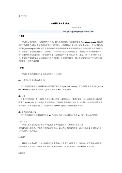
2.分类电路板的解剖式破坏性切片法大体上可分为三类:(1) 一般切片(正式名称为微切片)可对通孔区及板面其它区域灌满封胶后做了垂直切片(Vertical Section),也可对通孔做水平切片(Horizo ntal Section)是一般常见的做法。
(见杂志NO:4 P37,附图见后)(2) 切孔是小心用钻石锯片将一排通孔自正中央切成两半,或用砂纸将一排通孔磨去一半,将切半不封胶的通孔置于20x-40x的立体显微镜(或称实体显微镜)下观察半个孔壁的全部情况。
此时若也将通孔的后背再磨的很薄时,则底材将呈透明状,可进行背光法(Back light)检查孔铜层敷盖的情形。
(3) 斜切片(45°或30°)可对多层板面区或通孔区做层次间45°的斜切,然后以实体显微镜观察45°切面上导体间的情形。
3.制作技巧除第二类切孔法是用以观察半个孔壁的原状表面情况外,其余第一及第三类都需最后的仔细抛光,才能看到各种真实的情况,此点为切片的成败关键,此点至为重要不可掉以轻心。
以下为制作过程的重点。
microchip数字电源方案

microchip数字电源方案微控制器(MCU)是现代电子产品中不可或缺的关键组件。
作为一种用于执行控制和计算的集成电路,MCU需要稳定、可靠的电源方案来确保其正常运行。
微芯片数字电源方案是一种为MCU提供电源的解决方案,它采用数字控制和监测技术,以提高效率、精度和稳定性。
在微芯片数字电源方案中,主要包括以下几个关键元素和特点:1. 开关电源:数字电源方案通常使用开关电源作为电源的基础。
开关电源具有高效率和快速响应的特点,可以提供稳定的电压和电流输出。
2. 数字控制:数字电源方案使用数字控制技术,可以实现对电源输出的精确控制。
通过数字控制器,可以根据需要调整电源的输出电压和电流,并实时监测电源的工作状态。
3. 电流保护:数字电源方案还包括对电流的保护机制。
它可以监测电源输出的电流并根据需要进行限制,防止电源过载和短路等情况发生,提高系统的安全性和可靠性。
4. 温度监测:为了进一步提高电源的可靠性,数字电源方案通常还包括温度监测功能。
通过实时监测电源工作的温度,可以及时采取措施来避免因过热而导致的故障。
5. 效率优化:数字电源方案还可以通过采用各种优化技术来提高效率。
例如,可采用功率因素校正技术来提高系统的功率因数,减少能量的浪费。
通过微芯片数字电源方案,可以为MCU提供高效、稳定、可靠的电源。
它具有精确的控制和监测能力,可以根据需求调整电源的输出,并提供多种保护机制,以确保系统的安全性和可靠性。
此外,数字电源方案还可以通过优化技术提高电源的效率,降低能源消耗。
总之,微芯片数字电源方案是提供MCU电源的一种高效、稳定、可靠的解决方案。
它通过数字控制和监测技术,可以实现对电源输出的精确控制,并提供多种保护机制和优化技术,以提高系统的安全性和效率。
Microchip技术(微芯片技术)DS50003501A-页1:电子拨码按键接口引脚配置指南说明书
Hall Interface v4.2 User GuideIntroduction (Ask a Question)Brush Less DC (BLDC) motors are fitted with digital Hall sensors that provides rotor information for commutationof phases. The Hall sensors are used for block commutation of BLDC phases and provide rotor position with poor resolution. Block commutation has drawbacks like torque ripple and reduced efficiency. It is proven that vector control gives the best performance for the BLDC motor in terms of efficiency and torque ripple. However, because of poor angle resolution Hall sensors cannot be used for vector control. The Hall interface block generates high resolution angle from the low resolution angle provided by Hall sensors. It also computes the speed of the motor based on Hall signals.Summary (Ask a Question)The following table provides a summary of the Hall Interface characteristics.Table 1. Hall Interface CharacteristicsFeatures (Ask a Question)Hall Interface has the following key features:•Computes the raw angle from the hall inputs•Computes the filtered speed from the angleImplementation of IP Core in Libero Design Suite (Ask a Question)IP core must be installed to the IP Catalog of the Libero SoC software. This is done automatically through the IP Catalog update function in the Libero SoC software, or the IP core is manually downloaded from the catalog. Once the IP core is installed in the Libero SoC software IP Catalog, the core is configured, generated, and instantiated within the SmartDesign tool for inclusion in the Libero project list.Device Utilization and Performance (Ask a Question)The following table lists the device utilization used for Hall Interface.Table 2. Hall Interface UtilizationImportant: 1.The data in this table is captured using typical synthesis and layout settings. CDR reference clocksource was set to Dedicated with other configurator values unchanged.2.Clock is constrained to 200 MHz while running the timing analysis to achieve the performancenumbers.Table of ContentsIntroduction (1)Summary (1)Features (1)Implementation of IP Core in Libero Design Suite (1)Device Utilization and Performance (2)1. Functional Description (4)1.1. Angle Generation (4)1.1.1. Speed Calculation (5)2. Hall Interface Parameters and Interface Signals (7)2.1. Inputs and Outputs Signals (7)3. Timing Diagrams (8)4. Testbench (9)4.1. Simulation (9)5. Revision History (11)Microchip FPGA Support (12)Microchip Information (12)The Microchip Website (12)Product Change Notification Service (12)Customer Support (12)Microchip Devices Code Protection Feature (12)Legal Notice (13)Trademarks (13)Quality Management System (14)Worldwide Sales and Service (15)1. Functional Description (Ask a Question)This section describes the implementation details of the Hall interface block.The following figure shows the system level block diagram of the Hall interface.Figure 1-1. System Level Block Diagram of Hall Interface BlockThe Hall interface block generates the rotor angle based on three Hall inputs:•The angle_out_raw_o output is the raw angle generated based on Hall events•The theta_output_o output is the smoothened interpolated angle•The hall_sensor_pol_i input is used to indicate, if the Hall signals are active high or active lowThe angle generated is used to determine the rotor speed. The clear_buffer_i input is used to clear the speed filterbuffer when the motor is stopped. The computed speed is filtered using a filter block. The filter block computation is triggered by the fil_trig_i input and the filter time constant is decided by the filter_factor_i input. The filtered speed is available at omega_out_o output, and the omega_done_o output (pulse of one clock cycle width) indicates the speed is ready for use by the subsequent blocks.1.1 Angle Generation (Ask a Question)A Hall event is a change of state of the Hall signal. In one cycle of the Hall signal, six Hall events can be detected.Each event indicates an angle movement of one sixth of the total cycle. This means that eachHall event indicates a change of 60° (electrical).For ripple free operation, the raw angle is smoothened by interpolation to obtain a finer angle. This angle is usedin the field oriented control (FOC) transformation. The following figure shows the Hall angle signals and the anglegenerated from these signals (assuming the Hall signals are active high).Figure 1-2. Hall Signals and Angle GenerationHall BHall CRaw Angle and Interpolated Angle(dotted)Hall AThe following figure shows the computed angle generation for the reverse direction of the active high Hall signals.Figure 1-3. Hall Signals and Angle Generation for Reverse DirectionHall AHall BHall CRaw Angle and Interpolated Angle(dotted)1.1.1 Speed Calculation (Ask a Question)The rotor speed is calculated based on the change of angle in a given time window. The time window varies based on the motor speed and the speed obtained is scaled appropriately.The Hall sensors provide the electrical angle of the rotor. The mechanical speed is affected by the number of pole pairs. The Hall interface block uses the number of pole pairs to compute the scaling factor. The speed factor is calculated as:Hall Interface Parameters and Interface Signals 2. Hall Interface Parameters and Interface Signals (Ask a Question)This section discusses the parameters in the Hall interface I/O signals.2.1 Inputs and Outputs Signals (Ask a Question)The following table lists the input and output ports of the Hall Interface block.Table 2-1. Input and Output Ports of Hall InterfaceTiming Diagrams 3. Timing Diagrams (Ask a Question)This section discusses Hall Interface timing diagrams.The following figure shows the timing diagram of Hall Interface.Figure 3-1. Hall Interface Timing DiagramCLOCKha_ihb_ihc_iomega_done_i4. Testbench (Ask a Question)A unified test-bench is used to verify and test Hall Interface called as user test-bench. Testbench is provided to checkthe functionality of the Hall Interface IP.4.1 Simulation (Ask a Question)The following steps describe how to simulate the core using the testbench:1.Open the Libero SoC application, click Libero SoC Catalog tab, expand Solutions-MotorControl2.Double-click Hall Interface, and then click OK. The documentation associated with the IP are listed underDocumentation.Important: If you do not see the Catalog tab, navigate to View Windows menu and click Catalogto make it visible.Figure 4-1. Hall Interface IP Core in Libero SoC Catalog3.On the Stimulus Hierarchy tab, right-click the testbench (hall_interface_tb.v), point to Simulate Pre-Synth Design, and then click Open Interactively.Important: If you do not see the Stimulus Hierarchy tab, navigate to View > Windows menu andclick Stimulus Hierarchy to make it visible.Figure 4-2. Simulating Pre-Synthesis DesignModelSim opens with the testbench file as shown in the following figure.Figure 4-3. ModelSim Simulation WindowImportant: If the simulation is interrupted due to the runtime limit specified in the .do file, use the run -all command to complete the simulation.Revision History 5. Revision History (Ask a Question)The revision history describes the changes that were implemented in the document. The changes are listed byrevision, starting with the most current publication.Table 5-1. Revision HistoryMicrochip FPGA Support (Ask a Question)Microchip FPGA products group backs its products with various support services, including Customer Service, Customer Technical Support Center, a website, and worldwide sales offices. Customers are suggested to visit Microchip online resources prior to contacting support as it is very likely that their queries have been already answered.Contact Technical Support Center through the website at /support. Mention the FPGA Device Part number, select appropriate case category, and upload design files while creating a technical support case.Contact Customer Service for non-technical product support, such as product pricing, product upgrades, update information, order status, and authorization.•From North America, call 800.262.1060•From the rest of the world, call 650.318.4460•Fax, from anywhere in the world, 650.318.8044Microchip Information (Ask a Question)The Microchip Website (Ask a Question)Microchip provides online support via our website at /. This website is used to make files and information easily available to customers. Some of the content available includes:•Product Support – Data sheets and errata, application notes and sample programs, design resources, user’s guides and hardware support documents, latest software releases and archived software•General Technical Support – Frequently Asked Questions (FAQs), technical support requests, online discussion groups, Microchip design partner program member listing•Business of Microchip – Product selector and ordering guides, latest Microchip press releases, listing of seminars and events, listings of Microchip sales offices, distributors and factory representativesProduct Change Notification Service (Ask a Question)Microchip’s product change notification service helps keep customers current on Microchip products. Subscribers will receive email notification whenever there are changes, updates, revisions or errata related to a specified product family or development tool of interest.To register, go to /pcn and follow the registration instructions.Customer Support (Ask a Question)Users of Microchip products can receive assistance through several channels:•Distributor or Representative•Local Sales Office•Embedded Solutions Engineer (ESE)•Technical SupportCustomers should contact their distributor, representative or ESE for support. Local sales offices are also available to help customers. A listing of sales offices and locations is included in this document.Technical support is available through the website at: /supportMicrochip Devices Code Protection Feature (Ask a Question)Note the following details of the code protection feature on Microchip products:•Microchip products meet the specifications contained in their particular Microchip Data Sheet.•Microchip believes that its family of products is secure when used in the intended manner, within operating specifications, and under normal conditions.•Microchip values and aggressively protects its intellectual property rights. Attempts to breach the code protection features of Microchip product is strictly prohibited and may violate the Digital Millennium Copyright Act.•Neither Microchip nor any other semiconductor manufacturer can guarantee the security of its code. Code protection does not mean that we are guaranteeing the product is “unbreakable”. Code protection is constantly evolving. Microchip is committed to continuously improving the code protection features of our products. Legal Notice (Ask a Question)This publication and the information herein may be used only with Microchip products, including to design, test,and integrate Microchip products with your application. Use of this information in any other manner violates these terms. Information regarding device applications is provided only for your convenience and may be supersededby updates. It is your responsibility to ensure that your application meets with your specifications. Contact yourlocal Microchip sales office for additional support or, obtain additional support at /en-us/support/ design-help/client-support-services.THIS INFORMATION IS PROVIDED BY MICROCHIP "AS IS". MICROCHIP MAKES NO REPRESENTATIONSOR WARRANTIES OF ANY KIND WHETHER EXPRESS OR IMPLIED, WRITTEN OR ORAL, STATUTORYOR OTHERWISE, RELATED TO THE INFORMATION INCLUDING BUT NOT LIMITED TO ANY IMPLIED WARRANTIES OF NON-INFRINGEMENT, MERCHANTABILITY, AND FITNESS FOR A PARTICULAR PURPOSE, OR WARRANTIES RELATED TO ITS CONDITION, QUALITY, OR PERFORMANCE.IN NO EVENT WILL MICROCHIP BE LIABLE FOR ANY INDIRECT, SPECIAL, PUNITIVE, INCIDENTAL, OR CONSEQUENTIAL LOSS, DAMAGE, COST, OR EXPENSE OF ANY KIND WHATSOEVER RELATED TO THE INFORMATION OR ITS USE, HOWEVER CAUSED, EVEN IF MICROCHIP HAS BEEN ADVISED OF THE POSSIBILITY OR THE DAMAGES ARE FORESEEABLE. TO THE FULLEST EXTENT ALLOWED BY LAW, MICROCHIP'S TOTAL LIABILITY ON ALL CLAIMS IN ANY WAY RELATED TO THE INFORMATION OR ITS USE WILL NOT EXCEED THE AMOUNT OF FEES, IF ANY, THAT YOU HAVE PAID DIRECTLY TO MICROCHIP FOR THE INFORMATION.Use of Microchip devices in life support and/or safety applications is entirely at the buyer's risk, and the buyer agrees to defend, indemnify and hold harmless Microchip from any and all damages, claims, suits, or expenses resulting from such use. No licenses are conveyed, implicitly or otherwise, under any Microchip intellectual property rights unless otherwise stated.Trademarks (Ask a Question)The Microchip name and logo, the Microchip logo, Adaptec, AVR, AVR logo, AVR Freaks, BesTime, BitCloud, CryptoMemory, CryptoRF, dsPIC, flexPWR, HELDO, IGLOO, JukeBlox, KeeLoq, Kleer, LANCheck, LinkMD, maXStylus, maXTouch, MediaLB, megaAVR, Microsemi, Microsemi logo, MOST, MOST logo, MPLAB, OptoLyzer, PIC, picoPower, PICSTART, PIC32 logo, PolarFire, Prochip Designer, QTouch, SAM-BA, SenGenuity, SpyNIC, SST, SST Logo, SuperFlash, Symmetricom, SyncServer, Tachyon, TimeSource, tinyAVR, UNI/O, Vectron, and XMEGA are registered trademarks of Microchip Technology Incorporated in the U.S.A. and other countries.AgileSwitch, APT, ClockWorks, The Embedded Control Solutions Company, EtherSynch, Flashtec, Hyper Speed Control, HyperLight Load, Libero, motorBench, mTouch, Powermite 3, Precision Edge, ProASIC, ProASIC Plus, ProASIC Plus logo, Quiet- Wire, SmartFusion, SyncWorld, Temux, TimeCesium, TimeHub, TimePictra, TimeProvider, TrueTime, and ZL are registered trademarks of Microchip Technology Incorporated in the U.S.A.Adjacent Key Suppression, AKS, Analog-for-the-Digital Age, Any Capacitor, AnyIn, AnyOut, Augmented Switching, BlueSky, BodyCom, Clockstudio, CodeGuard, CryptoAuthentication, CryptoAutomotive, CryptoCompanion, CryptoController, dsPICDEM, , Dynamic Average Matching, DAM, ECAN, Espresso T1S, EtherGREEN, GridTime, IdealBridge, In-Circuit Serial Programming, ICSP, INICnet, Intelligent Paralleling, IntelliMOS, Inter-Chip Connectivity, JitterBlocker, Knob-on-Display, KoD, maxCrypto, maxView, memBrain, Mindi, MiWi, MPASM, MPF, MPLAB Certified logo, MPLIB, MPLINK, MultiTRAK, NetDetach, Omniscient Code Generation, PICDEM, , PICkit, PICtail, PowerSmart, PureSilicon, QMatrix, REAL ICE, Ripple Blocker, RTAX, RTG4, SAM-ICE, Serial Quad I/O, simpleMAP, SimpliPHY, SmartBuffer, SmartHLS, SMART-I.S., storClad, SQI, SuperSwitcher, SuperSwitcher II, Switchtec, SynchroPHY, Total Endurance, Trusted Time, TSHARC, USBCheck, VariSense, VectorBlox, VeriPHY, ViewSpan, WiperLock, XpressConnect, and ZENA are trademarks of Microchip Technology Incorporated in the U.S.A. and other countries.SQTP is a service mark of Microchip Technology Incorporated in the U.S.A.The Adaptec logo, Frequency on Demand, Silicon Storage Technology, and Symmcom are registered trademarks of Microchip Technology Inc. in other countries.GestIC is a registered trademark of Microchip Technology Germany II GmbH & Co. KG, a subsidiary of Microchip Technology Inc., in other countries.All other trademarks mentioned herein are property of their respective companies.© 2023, Microchip Technology Incorporated and its subsidiaries. All Rights Reserved.ISBN: 978-1-6683-2142-3Quality Management System (Ask a Question)For information regarding Microchip’s Quality Management Systems, please visit /quality.Worldwide Sales and Service。
microchip数字电源方案

microchip数字电源方案数字电源方案是一种通过数字控制和管理电源输出的技术,它在现代电子设备中发挥着重要作用。
在数字电源方案中,微芯片(Microchip)公司是一家全球领先的提供数字电源芯片和解决方案的厂商。
本文将介绍Microchip数字电源方案的特点、应用以及未来的发展趋势。
一、Microchip 数字电源方案的特点Microchip的数字电源方案具有以下特点:1. 高度集成:Microchip的数字电源芯片集成了多种功能,如 DC-DC 转换器、PWM 控制器、锁相环、电流传感器等,能够实现高效率的功率转换和精确的电源管理。
这种高度集成的设计大大简化了电源系统的设计和布局,提高了系统的可靠性和性能。
2. 高性能:Microchip的数字电源方案采用先进的控制算法和优化的电源管理策略,能够精确地调节电压和电流输出,并提供高效率的能量转换。
这些特性使得数字电源方案适用于广泛的应用领域,如工业自动化、通信设备、汽车电子等。
3. 灵活可配置:Microchip的数字电源芯片具有灵活的配置和编程能力,能够适应不同的电源系统要求。
用户可以通过软件调整输入输出参数、控制模式和保护功能,以实现最佳的电源管理效果。
这种灵活性和可配置性使得数字电源方案能够满足不同应用的需求,提供定制化的解决方案。
4. 高度可靠:Microchip的数字电源芯片经过严格的质量控制和可靠性测试,具有高度的可靠性和稳定性。
这种可靠性保证了电源系统在长时间运行和恶劣环境下的稳定性能,为设备的可靠运行提供了保障。
二、Microchip 数字电源方案的应用Microchip的数字电源方案广泛应用于各种电子设备和应用领域,包括但不限于以下几个方面:1. 工业自动化:在工业自动化系统中,数字电源方案能够提供高效、稳定的电源供应,满足工业设备对电能质量和可靠性的要求。
例如,在机器人控制系统中,数字电源方案能够实现对电机驱动器的精确控制,提高机器人的运动性能和精度。
microchip烧录算法

microchip烧录算法
Microchip烧录算法是一种用于将程序代码烧入Microchip微控制器中的技术。
通过这个算法,我们可以将程序逐步加载到芯片的非易失性存储器中,以便在以后的操作中执行。
烧录算法的第一步是选择适当的编程器和编程软件。
这些工具将帮助我们与目标微控制器建立连接,并将程序加载到芯片中。
一旦连接建立,我们就可以开始编写程序代码。
在编写代码之前,我们需要了解目标微控制器的体系结构和指令集。
这将帮助我们理解如何编写适合该芯片的程序。
我们还需要考虑程序的大小和复杂性,以确保它可以适应芯片的存储空间。
编写程序代码时,我们应该遵循一些最佳实践。
首先,我们应该使用清晰简洁的代码风格,使代码易于阅读和理解。
其次,我们应该避免使用复杂的逻辑和嵌套层次,以减少错误和调试的难度。
完成程序代码后,我们可以将其编译成目标微控制器可以执行的机器码。
编译器将代码转换为与目标芯片兼容的指令集,并进行优化以提高执行效率。
编译完成后,我们可以使用烧录器将程序加载到芯片中。
烧录器将逐步将机器码写入芯片的存储器中,以确保程序正确地存储在芯片中。
一旦程序成功烧录到芯片中,我们可以通过重启芯片来执行程序。
芯片将开始按照程序的指令执行相应的任务,从而实现预期的功能。
Microchip烧录算法是嵌入式系统开发中不可或缺的一部分。
通过合理的编程和烧录过程,我们可以确保程序正确地加载到Microchip 微控制器中,并实现预期的功能。
这为我们开发高效稳定的嵌入式系统提供了保障。
Microchip推出Microchip增强型中档内核超低功耗的18引脚PIC单片机
Microchip推出Microchip增强型中档内核超低功耗的18
引脚PIC单片机
佚名
【期刊名称】《半导体技术》
【年(卷),期】2010()1
【摘要】2009年12月16日,单片机和模拟半导体供应商美国微芯科技公司宣布,推出PIC16(L)F1826和PIC16(L)F1827[PIC16(L)F1826/7]通用8位单片机(MCU),这是采用公司增强型中档内核的最新款PIC㈣MCU。
作为此内核向18引脚扩展的首款产品,PIC16(L)F1826/7MCU提供了一个先进的外设集,
【总页数】1页(P101-101)
【关键词】PIC单片机;Microchip;增强型;超低功耗;内核;引脚;中档;美国微芯科技公司
【正文语种】中文
【中图分类】TP368.1;TP242.6
【相关文献】
1.Microchip推出超低功耗的18引脚PIC单片机/德州仪器最新数据采集系统将功耗、占用空间以及成本锐降75% [J],
2.Microchip推出首批具备增强型中档8位内核的PIC(R)单片机系列 [J], Microchip公司
3.Microchip推出超低功耗的18引脚PIC单片机 [J], 无
4.Microchip推出采用Microchip增强型中档内核、业界领先超低功耗的18引脚PIC单片机 [J],
5.Microchip推出采用增强型中档内核的18引脚PIC单片机 [J],
因版权原因,仅展示原文概要,查看原文内容请购买。
- 1、下载文档前请自行甄别文档内容的完整性,平台不提供额外的编辑、内容补充、找答案等附加服务。
- 2、"仅部分预览"的文档,不可在线预览部分如存在完整性等问题,可反馈申请退款(可完整预览的文档不适用该条件!)。
- 3、如文档侵犯您的权益,请联系客服反馈,我们会尽快为您处理(人工客服工作时间:9:00-18:30)。
PCB布线设计(之五)
2004-08-09Microchip公司Bonnie 点击: 1430
PCB布线设计(之五)
要解决信号完整性问题,最好有多个工具分析系统性能。
如果在信号路径中有一个A/D转换器,那么当评估电路性能时,很容易发现三个基本问题:所有这三种方法都评估转换过程,以及转换过程与布线及电路其它部分的交互作用。
三个关注的方面涉及到频域分析、时域分析和直流分析技术的使用。
本文将探讨如何使用这些工具来确定与电路布线有关问题的根源。
我们将研究如何决定找什么;到哪里找;如何通过测试检验问题;以及如何解决发现的问题等。
图1 SCX015压力传感器输出端的电压由仪表放大器(A1和A2)放大。
在仪表放大器之后,添加了一个低通滤波器 (A3),以消除来自12位A/D转换器转换的混叠噪声
图2 来自于12位A/D转换器MCP3201的数据的时域表示,产生了有趣的周期信号。
此信号源可追溯到电源
图3 电源噪声充分降低后,MCP3201的输出码
一直是一个码,2108
本文要论述的电路如图1所示。
电源噪声
电路应用中的常见干扰源来自电源,这种干扰信号通常通过有源器件的电源引脚引入。
例如,图1中A/D 转换器输出的时序图如图2所示。
在此图中,A/D转换器的采样速度是40ksps,进行了4096次采样。
在此例中,仪表放大器、参考电压源和A/D转换器上没有加旁路电容。
另外,电路的输入都是以一个低噪声、2.5V的直流电压源作为基准。
对电路的深入研究表明,时序图上看到的噪声源来自于开关电源。
电路中添加了旁路电容和扼流环。
电源上加了一个10mF的电容,并且在尽可能靠近有源元件的电源引脚旁放置了三个0.1mF的电容。
在产生的新时序图上可以看到,产生了稳定的直流输出,图3所示的柱状图可验证这一点。
数据显示,电路的这些更改消除了来自电路信号路径的噪声源。
造成干扰的外部时钟
其它系统噪声源可能来自时钟源或电路中的数字开关。
如果这种噪声与转换过程有关,它不会作为转换过程中的干扰出现。
但是,如果这种噪声与转换过程无关,采用FFT(快速傅立叶变换)分析,可以很容易发现这种噪声。
图4 耦合到模拟走线的数字噪声有时被误解为宽带噪声。
FFT图可以很容易识别这种所谓“噪声”的频率,因此可识别出噪声源
图5 放大器轻微过激励,会使信号产生失真。
通过这种转换的FFT图,可以很快发现信号的失真
时钟信号干扰的示例可参见图4所示的FFT图。
此图使用了图1所示的电路,并添加了旁路电容。
在图4所示的FFT图中看到的激励,由电路板上的19.84MHz时钟信号产生。
在此例中,布线时几乎没有考虑走线之间的耦合作用,在FFT图中可以看到忽略此细节的结果。
这个问题可以通过修改布线来解决,将高阻抗模拟走线远离数字开关走线;或者在模拟信号路径中,在A/D转换器之前加抗混叠滤波器。
走线之间的随机耦合在某种程度上更难以发现,在这种情况下,时域分析可能比较有效。
放大器使用不恰当
回到图1所示的电路,在仪表放大器的正相输入端施加一个1kHz的交流信号。
此信号不是压力传感的特性,但是可以采用这个示例来说明模拟信号路径中器件的影响。
图5所示的FFT图显示了施加上述条件后的电路性能。
注意基波看起来有失真,许多谐波也有同样的失真。
失真是由于使放大器轻微过激励引起的。
解决此问题的方法是降低放大器增益。
结语
解决信号完整性问题可能会花费很多时间,尤其是当工程师没有工具来解决棘手的问题时。
在“窍门箱”中有三种最佳的分析工具:频域分析工具(FFT)、时域分析工具(示波器照片)和直流分析工具(柱状图)。
工程师可以用这些工具来识别电源噪声、外部时钟源和过激励放大器失真。
■。
