argu3 15 (3.10)
Argo网格化产品用户手册

其中 x i 和 yi 分别表示东西和南北的位置; t i 是时间; L x , L y 和 Lt 分别为长度和时 间尺度; Lt 为 120 小时; Lx 和 L y 的取法为:
Lx = 120000 /(0.35λ2 + 300), Ly = 120000 /(0.35λ2 + 400)
(3)
其中 λ 为纬度, Lx 和 L y 的单位是千米。 基于 1998-2009 年质控后的 Argo 温盐剖面数据, 采用上述方法制作气候态 背景场。
(4) (5)
Y (1) = Y obs − HX b (n ) ( n−1) ( n −1) ( n−1 ) Y = Y − H X , (n = 2,3, L, N )
其中, n 表示第 n 重网格,此处网格重数 N 为 9 重。粗网格对应长波模态,细网 格对应短波模态。 由于波长或相关尺度由网格的粗细来表达,因此背景场误差协 方差矩阵就退化为简单的平滑矩阵 S ( n ) 。最终分析结果就可以表示为:
图 3 2005 年 1 月至 2009 年 12 月 Nino3.4 区的 ENSO 指数时间序列图。
四、 联系方式
韩桂军,022-24010846,gjhan@ 吴新荣,022-24010848,wuxinrong@ 李 威,022-24010848,liwei@
Xa = Xb + X L = Xb +
∑X
n =1
N
(n )
(6)
即以网格的粗细来描述背景场误差协方差矩阵中的相关尺度, 在一组由粗到细的 网格上依次对观测场相对于背景场的增量进行三维变分分析, 在每次分析的过程 中, 将上次较粗网格上分析得到的分析场作为新的背景场代入到下次较细网格的 分析中, 而每次分析的增量也是指相对于上次较粗网格分析得到的新背景场而言 的增量,最后将各重网格的分析结果相叠加得到最终的分析结果。
RO系统安装及维修指南说明书
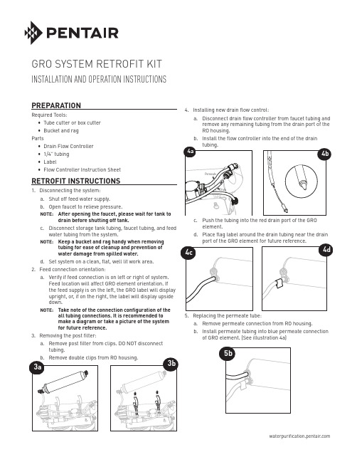
4.a.RO housing.b.a. Remove permeate connection from RO housing.b. Install permeate tubing into blue permeate connectionof GRO element. (See illustration 4a) PREPARATIONRequired Tools:• Tube cutter or box cutter• Bucket and ragPartsNOTE: Keep a bucket and rag handy when removingtubing for ease of cleanup and prevention ofwater damage from spilled water.d. Set system on a clean, flat, well lit work area.2. Feed connection orientation:a. Verify if feed connection is on left or right of system.Feed location will affect GRO element orientation. Ifthe feed supply is on the left, the GRO label will displayupright, or, if on the right, the label will display upsidedown.NOTE: Take note of the connection configuration of theall tubing connections. It is recommended tomake a diagram or take a picture of the systemfor future reference.3. Removing the post filter:a. Remove post filter from clips. DO NOT disconnecttubing.GRO SYSTEM RETROFIT KITINSTALLATION AND OPERATION INSTRUCTIONS6. Removing the RO housing.a. Remove feed tubing connection from RO housing.b. Remove RO housing from bracket/clip assembly.NOTE:tubing lengths as needed.8. Installing the post filter.a. Install post filter onto GRO element.9.a. Locate the permeate tube.b. Install the permeate check valve between the GROelement and the ASO valve. Ensure that the flow arrowon the permeate check is pointed towards the ASO valve.a. Connect system to faucet, storage tank and feed tubing.b. Keep storage tank valve closed. Turn on water at feedvalve, open faucet and flush GRO element for24 hours. Check for leaks at tubing connections duringpressurization and 24 hour flush.c. Follow flushing instructions as detailed in thesystem manual for sanitation, final flush and startupprocedures.WATER QUALITY SYSTEMS5730 NORTH GLEN PARK ROAD, MILWAUKEE, WI 53209P: 262.238.4400 | | CUSTOMER CARE: 800.279.9404 | tech-support@All Pentair trademarks and logos are owned by Pentair, Inc. or its affiliates. All other registered and unregistered trademarks and logos are the property of their respective owners. Because we are continuously improving our products and services, Pentair reserves the right to change specifications without prior notice.Pentair is an equal opportunity employer.4004456 REV A JL15 © 2015 Pentair Residential Filtration, LLC All Rights Reserved.For Pentair Product Warranties visit:Pentair para las garantías de los productos visite:Pour Pentair garanties produit visitez le site :}。
ADVANTEST U3741 U3751 U3771 U3772 说明书
MANUAL NUMBER C Printed in JapanADVANTEST CORPORATIONAll rights reserved .U3700 SeriesUser’s GuideFOE-8440185H00First printing November 20, 2004Applicable ModelsU3741U3751U3771U37722004Certificate of ConformityThis is to certify, thatcomplies with the provisions of the EMC Directive 89/336/EEC (All of these factors arerevised by 91/263/EEC,92/31/EEC,93/68/EEC) in accordance with EN61326and Low V oltage Directive 73/23/EEC (All of these factors are revised by 93/68/EEC)in accordance with EN61010.ADVANTEST Corp.ROHDE&SCHWARZ Tokyo, Japan Europe GmbHMunich, Germanyinstrument, type, designation3700.05Spectrum AnalyzerU3700 SeriesNo. CR B00CR-1有毒有害物质含量信息说明书•本有毒有害含量含量说明内容是为了贯彻[电子信息产品污染控制管理办法]而编制的。
This document is made for Chinese Administration on the Control of Pollution Caused by Electronic In-formation Products, unofficially called "China-RoHS".この文書は、中国の「電子情報製品汚染防止管理弁法」のための文書です。
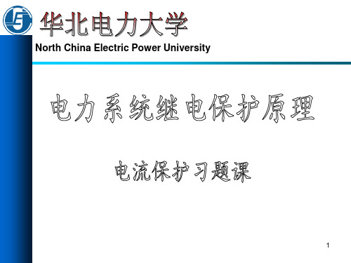
电流保护习题-讲解版
(
3 2
E II
set.1
ZS.max
Z AB )
1 ( 3 380 3 10 15) 23 2 3.87
105%
对于线路-变压器组, 电流速断保护能保护线路全长
16
3.设各保护都配置有三段式电流保护,参数如图所示。
110kV
60km
100km
ZSA: 15、、 20
400 A
t7 1.5s
ZSA: 15、 20
ZSB: 10、 12
Krel 1.2 KrelKrel1.1KSS 1.2 Kre 0.85 z10.4/kmt7 1.5s
解:Ⅱ段: IK B .m in2 3 Z s A m a E x Z A B2 3 1 1 0 2 0 3 2 4 1 0 3 1 2 5 0 A
5
解:线路长80km时:
3、灵敏度校验:
lmin % 1 (
l
Z AB
3 2
E II
set.1
ZS.max )
1 ( 3 115 3 18) 0.480 2 1.886
39% 15%
满足要求
6
解:线路长40km时: 1、定值计算:
I K I I set.1
I rel k.B.max
1.25 E Zs.min ZAB
I K I I
I
set.1
rel k.B.max
1.25 E Zs.min ZAB
1.25 115 3 4.15KA 12 0.420
2、时间: tA I B 0s
9
解:线路长20km时:
3、灵敏度校验:
lmin % 1 (
l
Z AB
3 2
Trigonox 311 3,3,5,7,7-Pentamethyl-1,2,4-trioxepan
Product Data SheetTrigonox 3113,3,5,7,7-Pentamethyl-1,2,4-trioxepaneTrigonox® 311 is a pure peroxide in liquid form.CAS number215877-64-8EINECS/ELINCS No. 455-560-2TSCA statuslisted on inventory Molecular weight 174.24Active oxygen content peroxide9.18%Concentration 8.72% min.SpecificationsAppearance Clear liquidAssay≥ 95.0 %ApplicationsTrigonox® 311 is a monofunctional peroxide which is used for the crosslinking of natural rubber and synthetic rubbers, as well as polyolefins. Safe processing temperature: 180°C (rheometer ts2 > 20 min.). Typical crosslinking temperature: 220°C (rheometer t90 about 12 min.).Thermal stabilityOrganic peroxides are thermally unstable substances, which may undergo self-accelerating decomposition. The lowest temperature at which self-accelerating decomposition of a substance in the original packaging may occur is the Self-Accelerating Decomposition Temperature (SADT). The SADT is determined on the basis of the Heat Accumulation Storage Test.SADT120°C (248°F)Method The Heat Accumulation Storage Test is a recognized test method for thedetermination of the SADT of organic peroxides (see Recommendations on theTransport of Dangerous Goods, Manual of Tests and Criteria - United Nations, NewYork and Geneva).StorageDue to the relatively unstable nature of organic peroxides a loss of quality can be detected over a period of time. To minimize the loss of quality, Nouryon recommends a maximum storage temperatureTs Max.40°C (104°F)Ts Min.15°C (59°F) to prevent crystallizationNote When stored under these recommended storage conditions, Trigonox® 311 willremain within the Nouryon specifications for a period of at least 12 months afterdelivery.Packaging and transportThe standard packaging is a 30-liter HDPE can (Nourytainer®) for 25 kg peroxide solution. Both packaging and transport meet the international regulations. For the availability of other packed quantities contact your Nouryon representative. Trigonox® 311 is classified as Organic peroxide type E; liquid, Division 5. 2; UN 3107.Safety and handlingKeep containers tightly closed. Store and handle Trigonox® 311 in a dry well-ventilated place away from sources of heat or ignition and direct sunlight. Never weigh out in the storage room. Avoid contact with reducing agents (e. g. amines), acids, alkalis and heavy metal compounds (e. g. accelerators, driers and metal soaps). Please refer to the Safety Data Sheet (SDS) for further information on the safe storage, use and handling of Trigonox® 311. This information should be thoroughly reviewed prior to acceptance of this product. The SDS is available at /sds-search.Major decomposition productsMethane, Acetone, Isopropyl acetate, 3-Hydroxy-1,3-dimethylbutyl acetate, 3-Methoxy-1,3-dimethylbutyl acetateAll information concerning this product and/or suggestions for handling and use contained herein are offered in good faith and are believed to be reliable.Nouryon, however, makes no warranty as to accuracy and/or sufficiency of such information and/or suggestions, as to the product's merchantability or fitness for any particular purpose, or that any suggested use will not infringe any patent. Nouryon does not accept any liability whatsoever arising out of the use of or reliance on this information, or out of the use or the performance of the product. Nothing contained herein shall be construed as granting or extending any license under any patent. Customer must determine for himself, by preliminary tests or otherwise, the suitability of this product for his purposes.The information contained herein supersedes all previously issued information on the subject matter covered. The customer may forward, distribute, and/or photocopy this document only if unaltered and complete, including all of its headers and footers, and should refrain from any unauthorized use. Don’t copythis document to a website.Trigonox® and Nourytainer are registered trademarks of Nouryon Functional Chemicals B.V. or affiliates in one or more territories.Contact UsPolymer Specialties Americas************************Polymer Specialties Europe, Middle East, India and Africa*************************Polymer Specialties Asia Pacific************************2022-6-30© 2022Polymer crosslinking Trigonox 311。
C-NERGYTM Actilion GHDR 15-4, Actilion GHDR 10-4,
C-NERGY TM Actilion GHDR 15-4, Actilion GHDR 10-4, Actilion QX依据GB/T 16483、GB/T 17519编制最初编制日期: 2021/9/29 修订日期: 2021/10/27 版本: 2.0化学品中文名称: C-NERGY TM Actilion GHDR 15-4, Actilion GHDR 10-4, Actilion QX 化学品英文名称: C-NERGY TM Actilion GHDR 15-4, Actilion GHDR 10-4, Actilion QX 企业名称: Imerys Graphite & Carbon Switzerland Ltd.地址: Strada Industriale 12, 6743, Bodio (Switzerland)邮政编码: 6743电话号码: +41-91873-2010传真: +41-91873-2019电子邮件地址:应急咨询电话: CHEMTREC China 4001204937推荐用途: 用作导电导热助剂、摩擦调节剂、锂离子主材料。
限制用途: 无可用信息。
紧急情况概述GHS 危险性类别未被分类。
标签要素象形图 (GHS CN) : 无警示词 (GHS-CN) : 无危险性说明 (GHS-CN) : 不适用。
防范说明 (GHS CN) :预防措施: 无可用信息。
事故响应: 无可用信息。
安全储存: 无可用信息。
废弃处置: 无可用信息。
物理和化学危险没有更进一步的信息。
健康危害没有更进一步的信息。
没有更进一步的信息。
其他危害没有更进一步的信息。
产品形态: 物质。
急救措施的描述吸入: 将人转移到空气新鲜处,保持呼吸舒适体位。
如感觉不适,呼叫解毒中心或医生。
皮肤接触: 用肥皂水清洗皮肤。
如发生皮肤刺激:求医/就诊。
眼睛接触: 如戴隐形眼镜并可方便地取出,取出隐形眼镜。
Kurz-Bedienungsanleitung testo 175-T3 说明书
testo 175-T3 Kurz-Bedienungsanleitung0973.1757/T/wh/PC-qxd/03.03Bitte beachten!Diese Kurz-Bedienungsanleitung dient zur zusätzlichen Orientierung vor Ort. Zur Inbetriebnahme und Programmierung des Datenloggers lesen Sie bitte die Bedienungsanleitung die dem Software-Set bzw. dem Interface beiliegt.NormenDieses Produkt erfüllt laut Konformitätsbescheinigung die Richtlinien gemäß 89/336/EWG.SicherheitshinweiseLesen Sie bitte die nachfolgenden Sicherheitshinweise aufmerksam durch:Messen Sie mit dem Gerät und externen Fühlern niemals an spanungsführenden Teilen, wenn das Gerät nicht ausdrücklich für die Strom-/ und Spannungsmessung freigegeben ist! Prüfen Sie vor jeder Messung, ob Anschlüsse durch einen Blindstopfen verschlossen oder ein passender Fühler gesteckt ist. Die in den technischen Daten angegebene Schutzklasse wird sonst nicht erreicht. Betreiben Sie das Gerät nur innerhalb der in den technischen Daten vorgegebenen Parameter. Behandeln Sie das Gerät nur sach- und bestimmungsgemäß. Öffnen Sie das Gerät nur, wenn dies zu Wartungszwecken ausdrücklich in der Bedienungsanleitung beschrieben ist. Wenden Sie niemals Gewalt an! Geben sie leere Batterien an den dafür vorgesehenen Sammelstellen ab. Senden Sie das Gerät nach Ende der Nutzungszeit direkt an uns. Wir sorgen für eine umweltschonende Entsorgung.Garantie24 MonateDisplaygespeicherter Messwert niedrigster gespeicherter Messwert höchster gespeicherter Messwert Zwischenmesswert 1 Messwerte Batteriekapazität oberer AlarmwertKanal 1Kanal 2Unterer Alarmwert Warten auf Start des Messprogramms Messprogramm läuft Messprogramm beendetEinheiten1 Zwischenmesswerte werden im Display angezeigt, jedoch nicht gespeichertBatteriekapazitätSymbolOFFKapazität75 bis 100%50 bis 75% 25 bis 50% 10 bis 25%<10% Batterie leer Daten auslesen Batterie wechselnTechnische DatenMessgröße ..................................................................Temperatur (°C/°F) Messwertaufnehmer ........................................TE-Typ K oder T (extern) Anzahl der Messkanäle ......................................................2 (2x extern) Messbereich ......................................................-50 bis +1000 °C (Typ K) ..............................................................................-50 bis +400 °C (Typ T) Genauigkeit Gerät ............................................±0,5 °C (-50 bis +70 °C) ............................................................±0,7% v. Mw. (+70,1 bis +1000 °C) ......................................................................................................±1 Digit Auflösung........................................................................................0,1 °C Messtakt ....................................................10 sec bis 24 h (frei wählbar) Lagertemperatur................................................................-40 bis +85 °C Betriebstemperatur ..............................................................0 bis +70 °C Betriebstemperatur Display ................................................0 bis +65 °C Speicherkapazität ......................................................16.000 Messwerte Schutzart ..........................................................................................IP 54 Gehäuse ....................................................................................ABS/TPE Abmessungen in mm (LxBxH) ..........................................82 x 52 x 30 Gewicht................................................................................................90g Batterie ..............................................................................Lithium (½ AA) Batteriestandzeit ..............................typisch: 2½ Jahre (Messrate:15 Min., (Betriebstemperatur: 0 bis +50°C,Display: An, Betriebsanzeige (grüne LED): Aus)显示器保存读数 最低保存读数 最高保存读数 中间读数 1 读数 电池容量 上限警报通道 1通道 2下限警报 等待测试 程序开始 测试程序正在运行 测试程序结束单位1 中间读数在显示屏上显示,但不被保存。
DELFIA Unconjugated Estriol (uE3) kit说明书

03.12.2015Kit ComponentsProduct code DescriptionA083-301 DELFIA Unconjugated Estriol (uE3) kit游离雌三醇测定试剂盒(时间分辨荧光法)说明书Components:13805543 uE3 Calibrators/Standards A-F13805713 E3-Eu tracer stock solution13805714 E3 Antiserum stock solution13803374 uE3 Assay BufferB117-100 DELFIA/AutoDELFIA Wash ConcentrateB118-100 DELFIA /AutoDELFIA Enhancement Solution B118-100, 1244-104, 1244-105, 4001-0010, B118-100J(在 1 页继续)· vPvB(高残留性、高生物浓缩性物质):不适用的叠氮化钠急性毒性, H300;对水环境的危害境的危害(在 2 页继续)· 有关储存条件的更多资料:没有.· 具体的最终用户无相关详细资料。
(在 3 页继续)较高:未决定.· 蒸气压:不适用的· 密度:未决定的· 相対密度未决定.· 蒸气密度不适用的· 蒸发速率不适用的· 溶解性水:可溶解的· n-辛醇/水分配系数:未决定.· 黏性:动态:不适用的运动学的:不适用的· 溶剂成份:有机溶剂:0.0 %· 其他信息无相关详细资料。
(在 4 页继续)· 额外的生态学资料:· 总括注解:通常来说对水是不危害的对水中的有机物有危害.· PBT(残留性、生物浓缩性、毒性物质) 及 vPvB(高残留性、高生物浓缩性物质)评价结果· PBT(残留性、生物浓缩性、毒性物质)不适用的· vPvB(高残留性、高生物浓缩性物质):不适用的· 其他副作用无相关详细资料。
基于三次谐波相角突变原理的发电机定子接地保护
文章编号:1000-3673(2000)12-0070-04基于三次谐波相角突变原理的发电机定子接地保护黄少锋1,孙 鹏2,王增平1,赵自刚3(1.华北电力大学电力系,北京100085; 2.湖北电力调度通信局,湖北省武汉市430077;3.河北电力调度通信局,河北省石家庄050021)A GENERATOR GROUNDING FAULT PROTECTION BASEDON PHASE-ANGLE MUTATION OF THIRD HARMONIC VOLTAGEHUANG Shao-feng1,SUN Peng2,WANG Zeng-ping1,ZHAO Zi-gang3(1.North China Electric Pow er U niversity,Beijing100085,China;2.Hubei Provincial Pow er Dispatch&Comm unication Bureau,Wuhan430077,Hubei Province,China;3.Hebei Provincial Power Dispatch&Communication Bureau,Shijiazhuang050021,Hebei Province,China)ABSTRACT:O n the basis of the theo ry o f phase-angle mutation of third harmonic vo ltage a protection scheme for gener ator stator g rounding fault and its alg orithm ar e put for war d.T his scheme is com pared with micr o-computer pr otective schemes based on other protection principles, compar ison result show s that this scheme is applicable for lar ge capacit y gener ator w ith all kinds of gr ounding sy stem, especially it is of hig h sensitivity under ar c suppression coil gr ounding or non-gro unding.Otherw ise,T his scheme pos-sesses high reliability,and is not pr one to affected by surg e suppressors installed at the terminals of large g enerat or.KEY WORDS:generator;st ator gr ounding fault protection; third harmo nic;phase-ang le mutation摘要:提出了基于3次谐波相角突变原理的发电机定子接地保护及其算法,用数字仿真方法分析了灵敏度并和其它原理的微机保护方案作了比较,结果表明该原理适用于各种接地方式的大型汽轮发电机,并且灵敏度很高。
欧洲药典7.5版
INDEX
To aid users the index includes a reference to the supplement in which the latest version of a text can be found. For example : Amikacin sulfate...............................................7.5-4579 means the monograph Amikacin sulfate can be found on page 4579 of Supplement 7.5. Note that where no reference to a supplement is made, the text can be found in the principal volume.
English index ........................................................................ 4707
Latin index ................................................................................. 4739
EUROPEAN PHARMACOPபைடு நூலகம்EIA 7.5
Index
Numerics 1. General notices ................................................................... 7.5-4453 2.1.1. Droppers...................
RSA3测试站商品说明说明书
T A I n s t r u m e n t sP a c k i n g t h e R S A3I n s t r u m e n tThis procedure will cover the steps to properly pack up the RSA3 for shipment.Packing Materials Provided:cartonShippingovenforShelfforaccessoriesBoxfoamOven/motorSkid3 Screws hold RSA to skid4 Z-brackets w/ screwsShoulderboltXducer lock bracket w/ screwMotor lock bracket w/ screwTools Required:Complete set of metric Allen KeysAdjustable wrenchComplete set of standard Allen keysSet of screwdriversStretch wrapStrapping kitHeavy duty lifting jackCartNOTE: Before attempting to ship RSA3 instrument, please be sure all the front and back panels are well screwed in position. RSA3 Test Station is about 275 Ibs. Enough manpower and adequate tools are required.1.) Clean air should be flowing through the instrument with the appropriate PRESSURE as indicated onthe right hand side of the instrument (Figure 1).Figure 12.). Get the Stage Lock Screw and 4mm Allen key ready.3.) Slide the Oven to the extreme left.4.) Switch ON the instrument and open Orchestrator Software on the Host Computer:Move the stage up OR down slowly to the position where the outer hole below the transducer corresponds with the inner hole (Figure 2).Figure 25.) Insert the Stage Lock Screw into the corresponding holes and tighten the screw carefully using 4mm Allen key.6.) Switch OFF the instrument.7.) Remove any tools from the transducer and motor tool holders.Figure 38.)Lock the transducer (Figure 3). Use locking plate and screw; tighten screw with 4mm Allen key. 9.) Using 3mm Allen key, remove motor cover completely.10.)11.)(Figure 5).12.) .Figure 513.) Carefully turn back of RSA3 Instrument towards you at about 30 degrees angle. Do not stretch cables and hoses.614.) Remove power cable from 220 Volt supply socket.15.) Remove any air hoses connected to air fittings.16.) Remove communication cable from ‘HOST’ 9DB Connector.17.) Remove LN2 Control cable from ‘N2 Heater’ and ‘N2’ 15 DB Connector, if applicable.18) Using the appropriate equipment, Cart and Lifting tool, move the instrument from Laboratoryworkbench to shipping Department.Back of the Pallet3 Inner HolesFigure 719.)The Pallet caddy has seven holes on it, the three inner holes are for bolting down the instrument from under the pallet, using the 3 metric Socket-head Cap Screws–M10 (Figure 7). The four outer holes with embedded threaded nuts are for bolting down the instrument with 4 Z-Brackets and standard short socket-head cap screws20.) Carefully lower the instrument on Pallet caddy.Place the instrument on pallet caddy so that 2 of the inner holes are on your left hand side (Figure 7).21.)Insert the M10 Socket cap screw with washer in the right hand side hole under the pallet (Figure 8). Set the hole to correspond with the threaded hole under the instrument and turn the bolt to ensure that it catches the threading. On the left hand side under the pallet there are 2 holes. Set the 2 holes under the pallet to correspond with the 2 threaded holes under the instrument, insert two M10 Socket head cap screw, and turn the bolts to ensure that they catch the threading. Once it is confirmed that all the 3 bolts are on the instrument, tighten the bolts slightly with 8mm metric hex key. Do not over tighten at this point.Figure 822.) Insert the 4 Hold down Z-Brackets in the 4 slots on the sides on the instrument (Figure 9). Use the 4short standard Socket-head screws with washers to secure the hold down Z-Brackets on the instrument and bolt them down carefully on the pallet with ¼” standard hex keys. Do not over-tighten the screws on the pallet so as not to damage the embedded threaded nuts in the pallet.Figure 923.) At this point, tighten M 10 Socket-head cap screws under the pallet securely.24) Wrap corrugated-foam shipping shelf on the Oven (Figure 10).Pack all accessories, cables and hoses into corrugated carton . Seal the box with heavy- duty tape.Figure 1025.) Place the carton filled with accessories on top of wrapped oven (Figure 11).26.) Stretch wrap instrument:Wrap the stretch plastic firmly around the instrument several times from the base to top. Ensure that there is no loose object on the pallet (Figure 12).11 Figure12Figure27.) Open corrugated carton and cover the instrument on the pallet. Use heavy-dutytape to seal the box.28.) Strap the box tight and secure on the pallet with the appropriate strapping tool andmaterials (Figure 13).30) DO NOT STACK anything on top of RSA3.31) Your instrument is now ready to ship.PLEASE CONTACT SERVICE DEPARTMENT IF FURTHER CLARIFICATION ON HOW TO PACKAGE SPECIFIC ACCESSORIES.TA Instruments strongly recommends using a MotorFreight Carrier!。
35 KV三相抗短路电容器更换套件安装说明书

35 kV three-phase bushing retrofit kit installation instructionsDISCLAIMER OF WARRANTIES AND LIMITATION OF LIABILITYThe information, recommendations, descriptions and safety notations in this document are based on Eaton Corporation’s (“Eaton”) experience and judgment and may not cover all contingencies. If further information is required, an Eaton sales office should be consulted. Sale of the product shown in this literature is subject to the terms and conditions outlined in appropriate Eaton selling policies or other contractual agreement between Eaton and the purchaser.THERE ARE NO UNDERSTANDINGS, AGREEMENTS, WARRANTIES, EXPRESSED OR IMPLIED, INCLUDING WARRANTIES OF FITNESS FOR A PARTICULAR PURPOSE OR MERCHANTABILITY, OTHER THAN THOSE SPECIFICALL Y SET OUT IN ANY EXISTING CONTRACT BETWEEN THE PARTIES. ANY SUCH CONTRACT STATES THE ENTIRE OBLIGATION OF EATON. THE CONTENTS OF THIS DOCUMENT SHALL NOT BECOME PART OF OR MODIFY ANY CONTRACT BETWEEN THE PARTIES. In no event will Eaton be responsible to the purchaser or user in contract, in tort (including negligence), strict liability or other-wise for any special, indirect, incidental or consequential damage or loss whatsoever, including but not limited to damage or loss of use of equipment, plant or power system, cost of capital, loss of power, additional expenses in the use of existing power facilities, or claims against the purchaser or user by its customers resulting from the use of the information, recommendations and descriptions contained herein. The information contained in this manual is subject to change without notice.ii35 KV CLASS THREE-PHASE BUSHING RETROFIT KIT INSTALLATION INSTRUCTIONS MN800005ENContentsSAFETY INFORMATIONSafety instructions (iv)PRODUCT INFORMATIONIntroduction (1)Acceptance and initial inspection (1)Handling and storage (1)Standards (1)INSTALLATION INSTRUCTIONS (2)iii35 KV CLASS THREE-PHASE BUSHING RETROFIT KIT INSTALLATION INSTRUCTIONS MN800005ENiv 35 KV CLASS THREE-PHASE BUSHING RETROFIT KIT INSTALLATION INSTRUCTIONS MN800005ENEaton meets or exceeds all applicable industry standards relating to product safety in its Cooper Power™ series products. We actively promote safe practices in the use and maintenance of our products through our service literature, instructional training programs, and the continuous efforts of all Eaton employees involved in product design, manufacture, marketing, and service.We strongly urge that you always follow all locally approved safety procedures and safety instructions when working around high voltage lines and equipment, and support our “Safety For Life” mission.Product informationIntroductionEaton provides instructions for removing the existing contact tube and gas valve from a 35 kV, 200 A three- phase rated Cooper Power™ series apparatus bushing and installing a new contact tube and gas valve.Read this manual firstRead and understand the contents of this manual and follow all locally approved procedures and safety practices before installing or operating this equipment.Additional informationThese instructions cannot cover all details or variationsin the equipment, procedures, or process described nor provide directions for meeting every possible contingency during installation, operation, or maintenance. For additional information, contact your Eaton representative.Acceptance and initial inspectionEach three-phase bushing retrofit kit is in good condition when accepted by the carrier for shipment. Upon receipt, inspect the shipping container for signs of damage. Unpack the three-phase bushing kit and inspect it thoroughly for damage incurred during shipment. If damage is discovered, file a claim with the carrier immediately.Handling and storageBe careful during handling and storage of the retrofit kit to minimize the possibility of damage. If the retrofit kit is to be stored for any length of time prior to installation, provide a clean, dry storage area.StandardsISO 9001 Certified Quality Management SystemFigure 1. Line illustration of three-phase apparatus bushing.135 KV CLASS THREE-PHASE BUSHING RETROFIT KIT INSTALLATION INSTRUCTIONS MN800005ENHigh Voltage. All associated apparatus must bede-energized during installation or maintenance. Failure to comply may result in death, severe personal injury, and equipment damage.Installation instructionsStep 1Remove the contact tube• Engage the driving blades of the contact tube removal wrench into two of the slots at the end of the contact tube. See Figure 2.• While applying pressure to the torque tool to prevent disengagement from the slots, rotate the contact tube counterclockwise. Approximately six revolutions will be required to remove contact tube.• Discard the contact tube.otee:N If you are not able to remove the contact tube, there are two possible causes:1. Contact tube slots are stripped and the wrench cannotbe engaged.2. The contract tube removal force required is so largethat the retainer pin securing the piston breaks. In this case, the contact rotates freely but doesn not back out. If either of these two items has occurred, the bushing will need to be replaced.Step 2Remove the gas valve• Remove the gas valve and valve spring from the bushing. If you cannot obtain the gas valve/spring, push valve back in and let the spring push it out to where you can grab it. See Figure 2.• Discard the gas valve.Gas ContacttubeO-ringFigure 2. Installation of contact spring/gas valve into busing.235 KV CLASS THREE-PHASE BUSHING RETROFIT KIT INSTALLATION INSTRUCTIONS MN800005ENStep 3Install the new gas valve• Assemble the O-Ring into the groove in the new gasvalve.• Lubricate the O-Ring with silicone grease.• Assemble the new gas valve onto the valve spring. Installthe valve spring/gas valve into the bushing. See Figure 2.otee:N Ensure the gas valve is engaged to the valve springafter installation.Step 4Install the new contact tube• Apply silicone grease to the O-ring on the contact tube.• Insert the contact tube partially into the bushing andengage the wrench into the slots at the end of thecontact tube.• Rotate the contact tube clockwise as you install it.Rotating the contact tube clockwise aids passage of theO-ring into the bushing.• Engage the threads of the contact tube into the threadsof the piston. Ensure the wrench is fully installed into theslots at the end of the contact tube. Torque the contacttube in to 15 ft-lbs.pin is broken and the bushing must be removed andreplaced. Dispose of the old bushing. Failure to complycould result in personal injury or equipment damage.335 KV CLASS THREE-PHASE BUSHING RETROFIT KIT INSTALLATION INSTRUCTIONS MN800005ENEaton1000 Eaton Boulevard Cleveland, OH 44122United StatesEaton’s Cooper Power Systems Division2300 Badger Drive Waukesha, WI 53188United States/cooperpowerseries© 2015 EatonAll Rights ReservedPrinted in USAPublication No. MN800005EN Rev 00 (Replaces S800391 Rev 1)Eaton is a registered trademark.All trademarks are propertyof their respective owners.For Eaton's Cooper Power series productinformation call 1-877-277-4636 or visit:/cooperpowerseries.。
ThermoTorch 10 3-in-1 手掌加温器、闪光灯和电源储备说明书
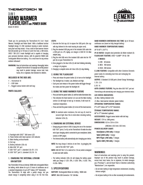
12345678Thank you for purchasing the ThermoTorch 10 3-in-1 Hand Warmer, Flashlight and Power Bank! With a traditional tactical flashlight design, it’s CNC aluminum housing is water resistant, dust proof and drop tested. It has a built in hand warmer feature that will provide up to 10 hours of scent free heat, a 300 lumen, CREE ® 5W LED 3 mode flashlight and is capable of charging your personal electronic devices, with its powerful 10000 mAh rechargeable lithium ion battery. It is a must have for any serious outdoor enthusiast!WARNING: R ead all instructions and warnings thoroughly beforeusing the T hermoTorch 10. Improper use of this product may result in product damage, excess heat, toxic fumes, fire or explosion. Not intended for children.INCLUDED IN THE BOX ARE:1 - ThermoTorch 101 - USB Cable1 - Rugged canvas holster with belt loopPARTS CALLOUT:1. Flashlight with CREE ® 300 lumen LED2. Power Button with Hand warmer LED indicator3. Main Heating surface/handle4. End cap5. Battery indicator LEDs (4)6. Mini USB “IN” port7. USB “OUT” port 1: (standard 2.0) 5V - 2.1A 8. USB “OUT” port 2: (standard 2.0) 5V - 1A1. CHARGING THE INTERNAL LITHIUMION BATTERYYour ThermoTorch 10 has an internal, 10000 mAh rechargeable lithium ion battery, which allows for up to 12 hours of continuous use ata constant temperature of up to 45° Celsius (113° Fahrenheit).The ThermoTorch 10 ships with a partial charge, but you should charge it completely before using it for the first time. STEPS1. Unscrew the End cap (4) to expose the USB ports (the cap will stay tethered to the main housing via nylon cord).2. P lug the standard USB plug end of the included USB cable into a USB port on a PC, laptop, car charger or USB 5V 2.1A Max adapter plug.3. P lug the mini USB end of the included USB cable into the “IN” port (6) on your ThermoTorch 10.4. Once plugged in, the blue LEDs (5) will start blinking indicating a charge is in progress.5. Charging is complete when all 4 blue LEDs (5) stop blinking.2. USING THE FLASHLIGHT• Press and release the power button (2) to turn on the flashlight.• T he flashlight has 3 modes: Low, Medium and High.• Each press and release of the power button will toggle through the modes and then power the flashlight off.3. USING THE HAND WARMER FEATURE• Press and hold the power button (2) until the button illuminates blue.• This indicates the Hand warmer is in use and the Main heating surface (3) will begin to heat up. In minutes, it will reach its maximum temperature.• P ress and hold the power button (2) to turn off the hand warmer.NOTE: To maintain water resistance, the end cap (4) must be secured tight. Bear this in mind when checking battery indicator LEDs (5).4. CHARGING AN EXTERNAL DEVICE• Simply plug your device’s USB 2.0 plug into one of the standard USB “OUT” ports (7 or 8)) on the ThermoTorch 10 while the other end of your charging cable is connected to your smartphone, tablet, camera or MP3 player.• T he internal battery will automatically start charging your device.NOTE: You may charge 2 devices at one time- by plugging into each of the USB “OUT” ports.NOTE: USB OUT Port 1 (7) is rated at 5v-2.1A out, which is designed to work best with tablets.• T he battery indicator LEDs (5) will display the battery power while you charge (1 LED- 25%, 2 LEDs- 50%, 3 LEDs- 75%, 4 LEDs- 100%)5. SPECIFICATIONS BATTERY:R echargeable lithium ion battery– 10000 mAh INPUT: M ini USB Connector / 5V 1.8A MaxHAND WARMER CONTINUOUS USE TIME: Up to 10 hours continuous use (based on fully charged battery)HAND WARMER TEMPERATURE RANGE: UP TO 45° C (113° F)IP-65 RATED: Complete dust protection (6) Water resistant (5)FLASHLIGHT FEATURE : CREE ® XLAMP ® XP-G2- 5W 3 MODES1. LOW: 60 lumens2. MED: 100 lumens3. HIGH: 300 lumensC-LINK FEATURE: Compatible with other Celestron Elements power banks for extending heat time and recharging the internal batteryOUTPUT: 2 Standard 2.0 USB ports (Smart Charge Technology): 1. 5V - 2.1A 2. 5V - 1AAUTO-CHARGE FEATURE: Plug into either USB “OUT” port andThermoCharge will automatically start charging your electronic device.LED STATUS INDICATORS: (4) Blue- Battery indicator LEDs(1) Blue- Hand warmer indicator (power button)OPERATING TEMPERATURE RANGE:0° to 45° Celsius (32° to 113° Fahrenheit)S TORAGE TEMPERATURE RANGE:68° to 77° Fahrenheit (optimal)ACCESSORIES: Rugged canvas holster with belt loop WEIGHT: 17.14 oz. (486 grams) DIMENSIONS: 8.2 in x 2.0 in x 2.0 in (208.3mm x 52.5 mm x 52.5 mm)POWER DELIVERY CHART:Smartphone (2100 mAh): 4 charges Tablet (8200 mAh): 1 charge MP3 Player (1100 mAh): 7 charges Sports CAM (1100 mAh): 7 charges______________________________________WARNINGS:Read all instructions and warnings prior to using this product. Improper use of this product may result in product damage, excess heat, toxic fumes, fire or explosion, for which damages you (“Purchaser”), and not Smart Team or Celestron (collectively “Manufacturer”) are responsible.• D o not store battery in high temperature environment, including intense sunlight.• D o not place battery in fire or other excessively hot environments.Model # 94553• B e cautious of excessive drops, bumps, abrasions or other impacts to this battery. If there is any damage to the battery such as dents, punctures, tears, deformities or corrosion, due to any cause, discontinue use and contact manufacturer or dispose of it in an appropriate manner at your local battery recycling center.• D o not disassemble this battery or attempt to repair or modify it in any manner.• D o not expose this battery to moisture or submerge it in liquid. • D o not attempt to charge battery using any method, apparatus or connection other than the device’s USB connector. For questions or instructions for the various ways to charge the Model #94553 3-in-1 Hand Warmer, Flashlight and Power Bank, refer to this manual.• D o not attempt to replace any part of this battery.• T his battery is intended for adult use only. If this battery is intended by Purchaser to be used by a minor, purchasing adult agrees to provide detailed instructions and warnings to any minor prior to use. Failure to do so is sole responsibility of Purchaser, who agrees to indemnify Manufacturer for any unintended use/misuse by a minor.• I f you find that your battery is excessively hot, is emitting odor, is deformed, abrased, cut or is experiencing or demonstrating an abnormal phenomenon, immediately stop all battery use and contact Manufacturer.• F or extended storage, first charge your battery for at least one hour.• I t is not recommended to store device for more than 3 months without use as batteries may have a tendency to discharge.• N ever dispose of batteries in the garbage. Disposal of batteries in the garbage is unlawful, in The United States, under state and federal environmental laws and regulations. Always take used batteries to your local battery-recycling center. DISCLAIMER:Manufacturer shall not in any way be liable to you or to any third party for any damages you or any third party may suffer as a result of use, intended or unintended, or misuse of this battery. Manufacturer will not be responsible for any damages you or any third party may suffer as a result of misuse of this battery as outlined above. If you are responsible for battery use with an unintended mobile device and damages result from such use, you agree to indemnify Manufacturer for any resulting injuries to any third party or parties.This device complies with part 15 of the FCC Rules. Operation is subject to the following two conditions:(1) This device may not cause harmful interference, and (2) this device must accept any interference received, including interference that may cause undesired operation.NOTE:This equipment has been tested and found to comply with the limits for a Class B digital device, pursuant to part 15of the FCC Rules. These limits are designed to providereasonable protection against harmful interference in aresidential installation. This equipment generates uses andcan radiate radio frequency energy and, if not installedand used in accordance with the instructions, may causeharmful interference to radio communications. However,there is no guarantee that interference will not occurin a particular installation. If this equipment does causeharmful interference to radio or television reception, whichcan be determined by turning the equipment off and on,the user is encouraged to try to correct the interferenceby one or more of the following measures:1. Reorient or relocate the receiving antenna.2. I ncrease the separation between the equipment andreceiver.3. C onnect the equipment into an outlet on a circuitdifferent from that to which the receiver is connected.4. Consult the dealer or an experienced technician for help. CAUTION :T o comply with the limits of the Class B digital device, pursuant to Part 15 of the FCC Rules, this device iscomply with Class B limits. All peripherals must beshielded and grounded. Operation with non-certifiedperipherals or non-shielded cables may results ininterference to radio or reception. MODIFICATION: A ny changes or modifications not expresslyapproved by the grantee of this device couldvoid the user’s authority to operate the device. Torrance, CA 90503TEL (800) 421-9649 | Copyright 2015 Celestron | All rights reserved. (Products or instructions may change withoutnotice or obligation.)Designed and intended for those 14 years of ageand older.V2.0。
- 1、下载文档前请自行甄别文档内容的完整性,平台不提供额外的编辑、内容补充、找答案等附加服务。
- 2、"仅部分预览"的文档,不可在线预览部分如存在完整性等问题,可反馈申请退款(可完整预览的文档不适用该条件!)。
- 3、如文档侵犯您的权益,请联系客服反馈,我们会尽快为您处理(人工客服工作时间:9:00-18:30)。
61.The following appeared in an article in the Grandview Beacon.
"For many years the city of Grandview has provided annual funding for the Grandview Symphony. Last year, however, private contributions to the symphony increased by 200 percent and attendance at the symphony's concerts-in-the-park series doubled. The symphony has also announced an increase in ticket prices for next year. Given such developments, some city commissioners argue that the symphony can now be fully self-supporting, and they recommend that funding for the symphony be eliminated from next year's budget."
Write a response in which you discuss what questions would need to be answered in order to decide whether the recommendation and the argument on which it is based are reasonable. Be sure to explain how the answers to these questions would help to evaluate the recommendation.
20.18
In this argument, the author concludes that the city commissioners recommend eliminate the symphony funding from Grandview budget due to the symphony can be fully self-supporting now based on following evidences. Private contributions to the symphony increased by 200 percent and attendance at the symphony's concerts-in-the-park series doubled. In addition, the symphony has also announced an increase in ticket prices for next year. The author conclusion is convincing at the fist glance, in fact, those evidences the author indicate still have several questions.
First of all, It is true that private contributions to the symphony increased by 200 percent, while we do not know the the how the original private contributions is? It is possible that the original private contributions very low, even if the private contributions increased 500 percent, the Grandview Symphony still need to the funding from the budget to maintain the daily pay of performance. Do not mention the 200 percent. To make the author more logical, the author should give the information of the original number of private contributions.
Secondly, the question is how much is original attendance at the symphony's concerts-in-the-park series. Perhaps, the original number of attendance is one hundred. Even though the attendance of symphony increased by 200 percent, the attendance of symphony still very low. In this way, a number of ticket still low, and they do not earn the money even to pay the fee of area and advertisement. Even if the original number of attendance of symphony is so many so that every concert does not leaves any empty seat. Increasing this number of attendance by decrease ticket prices, like this, they fundamentally cannot earn money. To strengthen the author conclusion, the arguer should provide more information about the original number of attendance and the ticket price.
last but not least, the fact that the symphony has also announced an increase in ticket prices for next year the author indicate. It's evidence is still vague. The symphony just announce that they will increase in ticket prices, but they do no take this action now. The next year the symphony indicate, but we do not know whether they will increase or maintain or even decrease. This evidence also lack of logical deduction, to strengthen this evidence, the author should ensure the ticket will increase, no matter what happened in pride of this year, even if the financial crisis.
To sum up, the author's conclusion lack of strong reason, so that hasty conclusion will break the prospect of the Grandview symphony. Therefor, in order to make a politic decision the author should provide more information to keep the society stationary.。
