Live Imaging Axon Stretch Growth Bioreactor
实时剪切波弹性成像技术在脂肪肝临床诊断中的价值

实时剪切波弹性成像技术在脂肪肝临床诊断中的价值实时剪切波弹性成像技术是一种新兴的医学成像技术,它通过观察器官和组织对外部压力的反应来实现对组织弹性特性的定量评估。
这项技术在临床诊断中具有广泛的应用前景,特别是在脂肪肝的诊断和评估中,其价值更是不可估量。
脂肪肝是一种常见的慢性肝脏疾病,其诊断和治疗对于患者的健康至关重要。
本文将介绍实时剪切波弹性成像技术在脂肪肝临床诊断中的价值,并探讨其在临床实践中的应用前景。
一、实时剪切波弹性成像技术介绍实时剪切波弹性成像技术是一种利用超声波成像仪器对组织进行实时弹性成像的技术。
它通过在组织表面施加外部压力,观察组织对外部压力的反应,从而测量组织的弹性模量。
这项技术不需要使用任何对患者有害的辐射,具有非侵入性、实时性和定量性强的特点,因此受到了广泛的关注。
脂肪肝是一种由于脂质代谢异常而导致肝脏脂肪堆积过多的疾病,它是一种常见的慢性肝脏疾病,临床症状轻微,但危害却很大。
传统的诊断方法包括血清生化指标、肝脏B超和组织活检等,但这些方法具有一定的局限性,无法对脂肪肝的程度和肝脏弹性情况进行准确评估。
而实时剪切波弹性成像技术具有定量、可靠、实时的特点,可以帮助医生对脂肪肝进行准确的诊断和评估。
实时剪切波弹性成像技术通过测量肝脏的弹性模量,可以及时发现和评估肝脏组织的硬度和弹性情况,从而判断脂肪肝的程度和严重程度。
通过这项技术可以实现对脂肪肝的早期诊断和预防,为患者提供更加及时的治疗和干预。
实时剪切波弹性成像技术在临床诊断中已经得到了广泛的应用,特别是在脂肪肝的诊断和评估中。
通过这项技术可以快速、准确地评估患者的脂肪肝程度,帮助医生了解患者的病情并制定相应的治疗方案。
与传统的诊断方法相比,实时剪切波弹性成像技术具有明显的优势,能够减少患者的不必要痛苦,减少医疗资源浪费,提高诊断的准确性和可靠性。
实时剪切波弹性成像技术还可以帮助医生监测脂肪肝的病情变化,及时调整治疗方案,提高治疗效果。
创新医疗博士生开发出新型光学成像技术提高癌症早期诊断

创新医疗博士生开发出新型光学成像技术提高癌症早期诊断近年来,癌症的发病率逐渐增加,对人类健康造成了严重威胁。
早期癌症的及时诊断对于有效治疗和提高患者生存率至关重要。
为了解决这一难题,一位创新医疗博士生成功开发出了一种新型光学成像技术,进一步提高了癌症早期诊断的准确性和敏感性。
该新型光学成像技术基于先进的光学方法和成像原理,能够高分辨率地观测到癌细胞的微观变化。
相比传统的医学成像技术,这种新技术克服了传统成像技术中分辨率较低、无法清晰显示微小病灶的缺陷。
通过将光学成像与计算机图像处理相结合,该技术能够更准确地检测和定位早期癌症病灶,为医生提供重要的参考信息。
该新型光学成像技术的研发过程经历了多个阶段。
首先,研究人员进行了大量的文献调研,深入了解了现有的医学成像技术的优缺点。
在此基础上,他们结合了生物医学工程和光学物理学的相关知识,设计并构建了实验室级的光学成像系统。
在实验室中,他们使用不同类型的癌细胞和动物模型进行了一系列的实验证明,验证了新技术的有效性和可行性。
在实验验证阶段取得成功后,研究人员将新技术应用于临床实践。
通过与多家医院合作,充分利用现有的临床样本,他们在一系列的临床实验中测试了新技术的准确性和可靠性。
结果显示,该新型光学成像技术在癌症早期诊断方面具有很高的敏感性和特异性,能够有效地检测到微小肿瘤和异常组织。
除了在早期癌症诊断中的应用,这种新型光学成像技术还具有广阔的发展前景。
它可以被用于其他疾病的诊断和研究,如心血管病、神经系统疾病等。
同时,该技术还可以为药物研发和治疗方案的制定提供重要的支持,帮助医生更好地了解疾病的发展过程和治疗效果。
虽然这项新型光学成像技术在癌症早期诊断方面取得了重大突破,但仍然面临着一些挑战和待解决的问题。
首先,技术的实施需要高成本的设备和专业的培训人员,这对于一些医院和地区来说可能具有一定的限制。
其次,技术的安全性和可靠性需要进一步验证和改进,确保其在临床应用中不会对患者造成损害。
深拓新型美容瘦脸针剂

第十届“春晖杯”创业大赛入围项目简介
项目编号
201பைடு நூலகம்00208
项目名称
深拓新型美容瘦脸针剂
应用行业领域
生物医药
第一参赛者姓名
王东升
留学国别/地区
美国
最高学历/学位
博士
现所在国家/地区
美国
项目概要:
肉毒素瘦脸针已然成为了当前医学美容届最受欢迎,最常见的美容注射剂,可以除皱、瘦脸、以及瘦腿,被誉为“美丽天使”。目前国际国内市场上成熟应用的是A型肉毒素,取得了良好效果。但同时人体对A型瘦脸针存在严重的耐药性,多次注射后效果显著降低,科研界在积极探索新的替代型和补充型,以提高安全性和解决耐药性。本项目公司研制成功了基于C型肉毒素的新一代改进型(Syntox,深拓),不但解决了耐药性,而且拥有更特异的靶点和更好的安全性。据美国食品药监局统计数字,C型是唯一一种没有引起人类发病的肉毒素。
本项目已申请美国专利,并于2014年底获得美国专利局正式审批。本项目团队成员科研技术力量雄厚,团队成员曾在国际顶尖期刊Nature, Science和Cell发表多篇学术论文。本项目市场前景广阔,不但涵盖无创美容整形市场,并且可拓展至医疗领域,具有千亿产业潜力。目前需要进行首轮融资,进行筹建生产设施以及临床前研发,投资将以股份形式回报。诚意与风险投资机构,国内美容、制药公司,以及政府创业园区洽谈融资以及合作业务。
活细胞成像技术的研究进展
活细胞成像技术的研究进展细胞是生命的基本单位,细胞内部发生的诸多过程也是生命活动的重要组成部分。
因此,对细胞内部活动的实时观察和研究显得极为重要。
近年来,随着活细胞成像技术的日益发展,人们可以实时观察细胞内部事件的发生,加深对生命科学的认识。
本文将从技术的发展历程、成像技术的种类、应用领域及前景等方面,全面阐述活细胞成像技术的研究进展。
一、技术的发展历程活细胞成像技术可以追溯到上个世纪中期。
20世纪50年代,对细胞的显微成像已经开始应用。
1953年,人类首次成功地观察到细胞内部的染色体结构和运动状态,进而推动了活细胞观察技术的发展。
60年代,出现了用荧光分析分子分布、交换、转移过程的追踪方法,成为细胞分子参与机制研究的重要手段之一。
随着计算机、数字成像技术等的发展,使得活细胞成像技术的观察精度和时间空间分辨率越来越高。
二、成像技术的种类1. 荧光共聚焦显微镜技术荧光共聚焦显微镜技术(confocal laser scanning microscopy, CLSM)是一种较为常见的活细胞成像技术,能够对生物样品进行非破坏性成像,在X-Y方向和Z方向上进行高分辨成像和立体成像。
该技术利用激光发出聚焦点,通过横向扫描样本,同时因厚度导致的散焦造成的模糊影响也被消除了。
适用于对细胞动态反应的实时成像、融合蛋白的二维和三维重建等。
2. 光片可控制镜技术光片可控制镜技术(spinning disk confocal microscopy, SDCM)是一种快速成像技术,样本成像速度快,能够用于快速成像大量细胞。
通过旋转大量的光学排列成的光片,甚至可以每秒钟旋转超过10000转对样品进行成像观察。
3. 双重共聚焦显微镜技术双重共聚焦显微镜技术(two-photon excitation fluorescence, TPEF)采用预聚焦技术,激发荧光物质由双重光子吸收,提高单点的荧光信号量,从而弱化了样品的对光损伤的效应,对于对细胞有损伤的样本有很好的应用。
活体成像在药物研发研究领域的应用

PerkinElmer 小动物活体光学成像技术已在生命科学基础研究、临床前医学研究及药物研发等领域得到广泛应用。
药物研发是科研机构和医药公司的重点研究领域。
在活体光学成像实验中,常用于药物研发的方法包括:1.使用构建好的生物发光转基因疾病动物模型,应用小动物活体光学成像技术观测给药后疾病信号的改变,从而评价药物对疾病的治疗效果。
2.通过注射功能性荧光探针,观测疾病发展过程中分子事件,从而反映药物对疾病的治疗效果。
下面结合一些具体实例阐述应用小动物活体光学成像技术进行药物研发的七个方面:1.抗肿瘤癌症药物研发。
2. 关节炎治疗药物研发。
3. 感染性疾病的药物研发。
4. 抗炎症的药物研发。
5. 抗病毒药物的研发。
6.神经系统疾病的药物治疗。
7.构建新型老鼠模型。
一.抗肿瘤癌症药物研发肝细胞性肝癌是肝癌的主要形式,而且每年死亡多达598,000人以上。
索拉非尼(Sorafenib )是一种合成的多酪氨酸激酶抑制剂,而且用于治疗30%的肝细胞性肝癌患者和肝硬化,因此研究人员开发其他类型的药物用于治疗肝癌患者。
表观遗传变换能够引发肝癌和促进肿瘤的发展,表观遗传变换而且是药物可逆的,因此转录后调控可用于肝癌的治疗。
DNA 异常甲基化是早期和晚期肿瘤癌症的重要事件,因此研究异常甲基化对于癌症风险性评估,治疗和化学预防都有积极的作用。
抑制DNA 甲基转移酶1(DNMT1,DNA methyltransferase 1) 能够再激活表观遗传沉默的肿瘤抑制基因,抑制肿瘤细胞生长,而且促进细胞分化,凋亡和提高免疫监督。
研究者在免疫缺陷的小鼠(NOD/SCID )脾内移植萤火虫荧光素酶标记的敏感人肝癌肿瘤细胞株(Huh7-luc ),从而建立人异种移植肝细胞性肝癌肿瘤模型。
使用PerkinElmer 的IVIS 系统成像显示小鼠服用低毒性的Zebularine (第二代稳定的亲水性DNA 甲基转移酶1抑制剂)后,生物发光强度明显降低(下图)。
如新华茂生生物光子扫描仪是什么

如新华茂生生物光子扫描仪是什么?在测量什么?它是根据诺贝尔奖理论(拉曼光谱理论),由美国犹他大学的物理学博士Gellermann和该校医学院多位研究者耗时6年共同研发的一种测量工具,可以简单、非侵入性地,不必抽血即可测量皮肤中类胡萝卜素的含量。
类胡萝卜是人体健康防护网路中很重要的一部分,因此皮肤中的类胡萝卜素含量的多寡是全身重要营养是否充足的一个重要指标,生物光子扫描仪可以帮助大学了解自己是否摄取多种且充足的营养素,包括蔬菜、水果和营养补充品。
皮肝胆类胡萝卜指数可以反应人体总抗氧化剂含量,因此它被比喻为“身体防御指数”。
为什么皮肤类春萝卜素可以反应整体抗氧化剂含量?因为类胡萝卜素的体内水平是人体总抗氧化状态的敏感指标,且和血液类春萝卜素及其他抗氧化剂(维生素C和E)有高度正相关性,与氧化压力(自由基伤害)具高度逆关联性。
类胡萝卜素主要存在于血液、脂肪和肝脏内,也存在于皮肤的表皮和角质层内。
其在皮肤中的存留时间较稳定,几乎或完全不受皮肤中其他生物分子的干扰。
皮肤类胡萝卜素的测定较之传统HPLC法测定血清类胡萝卜素,具有无创伤性、简便快捷、更精确地反映体内类胡萝卜素的稳态水平等优点。
为什么如新华茂生物光子扫描仪是值得信赖的?如新华茂已取得本技术在全球食品补充品市场的独家使用权,并且拥有两张美国政府专利(分别为测量技术及无创伤性测量类胡萝卜素的技术专利)。
换句话说,其它公司在2020年以前的专利保护期限里都不得使用本技术。
我们相信生物光子测量将会成为未来的优质测量工具,而如新华茂的伙伴则拥有可优先使用这种技术的权力。
如新华茂生物光子扫描仪能量化证明如沛及其它如新华茂产品可以改善我们的健康。
理想的生物光子扫描指数是多少?我们建议每个人都应养成良好的生活习惯,包括均衡饮食、补充适合的营养补充品、保持规律的运动习惯、避免吸烟及过度曝晒等,让自己的生物光子扫描指数达到50,000以上,才具有最佳的防御能力。
影响指数的一些主要因素有哪些:※每天蔬菜和水果的摄入※是否每天食用如沛营养素※吸烟(包括二手烟)※身体过度肥胖※暴露于污染环境中(厨房的油烟也是危险的杀手)※常在阳光下劳动或运动※感冒或有其他疾病,炎症产生的自由基可能导致指数下降。
活体荧光成像系统NEW技术简介活体生物荧光成像技术invivo
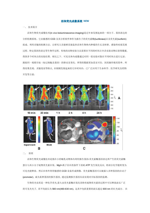
活体荧光成像系统NEW一、技术简介活体生物荧光成像技术(in vivo bioluminescence imaging)是近年来发展起来的一项分子、基因表达的分析检测系统。
它由敏感的CCD及其分析软件和作为报告子的荧光素酶(luciferase)以及荧光素(luciferin)组成。
利用灵敏的检测方法,让研究人员能够直接监控活体生物体内肿瘤的生长及转移、感染性疾病发展过程、特定基因的表达等生物学过程。
传统的动物实验方法需要在不同的时间点宰杀实验动物以获得数据, 得到多个时间点的实验结果。
相比之下,可见光体内成像通过对同一组实验对象在不同时间点进行记录,跟踪同一观察目标(标记细胞及基因)的移动及变化,所得的数据更加真实可信。
因其操作极其简单、所得结果直观、灵敏度高等特点, 在刚刚发展起来的几年时间内,已广泛应用于生命科学、医学研究及药物开发等方面。
二、原理活体生物荧光成像技术是指在小的哺乳动物体内利用报告基因-荧光素酶基因表达所产生的荧光素酶蛋白与其小分子底物荧光素在氧、Mg2+离子存在的条件下消耗ATP发生氧化反应, 将部分化学能转变为可见光能释放。
然后在体外利用敏感的CCD设备形成图像。
荧光素酶基因可以被插入多种基因的启动子(promoter), 成为某种基因的报告基因, 通过监测报告基因从而实现对目标基因的监测。
生物荧光实质是一种化学荧光,萤火虫荧光素酶在氧化其特有底物荧光素的过程中可以释放波长广泛的可见光光子, 其平均波长为560 nm(460-630 nm), 这其中包括重要的波长超过600 nm的红光成分。
在哺乳动物体内血红蛋白是吸收可见光的主要成分, 能吸收中蓝绿光波段的大部分可见光; 水和脂质主要吸收红外线, 但其均对波长为590-800 nm的红光至近红外线吸收能力较差, 因此波长超过600 nm的红光虽然有部分散射消耗但大部分可以穿透哺乳动物组织被敏感的CCD camera检测到。
小动物活体成像技术的应用进展

小动物活体成像技术的应用进展李珂;赵光【摘要】动物活体内光学成像(optical in vivo imaging)主要采用生物发光(bioluminescence)与荧光(fluorescence)两种技术在活体动物体内进行生物标记,通过成像系统来监测被标记动物体内分子及细胞等的发展进程,以及进行相关的生物、药物治疗研究[1-3].目前,国内、外实验动物成像的主要手段包括结构成像(解剖成像)及功能成像(分子成像).以optical-imaging、micro-PET、micro-SPET为代表的动物功能成像技术不但能即时反映活体动物内的细胞分布及基因表达,还能动态观察活体动物体内分子生物学过程,活体光学成像与micro-CT、MRI、ultrasound等结构成像手段结合,能为动物实验提供更客观的数据、更确切的分子生物特性.结合笔者所在医院IVIS LuminaⅡ型活体成像设备(living image)以及LivingImage(R)Software分析软件系统,对活体动物光学成像技术的应用进展综述如下.【期刊名称】《实用医药杂志》【年(卷),期】2012(029)001【总页数】2页(P81-82)【关键词】活体成像;生物发光;荧光;应用【作者】李珂;赵光【作者单位】471031河南洛阳,150医院全军肛肠外科研究所中心实验室;471031河南洛阳,150医院全军肛肠外科研究所中心实验室【正文语种】中文【中图分类】R-332动物活体内光学成像(optical in vivo imaging)主要采用生物发光(bioluminescence)与荧光(fluorescence)两种技术在活体动物体内进行生物标记,通过成像系统来监测被标记动物体内分子及细胞等的发展进程,以及进行相关的生物、药物治疗研究[1-3]。
目前,国内、外实验动物成像的主要手段包括结构成像(解剖成像)及功能成像(分子成像)。
以optical-imaging、micro-PET、micro-SPET为代表的动物功能成像技术不但能即时反映活体动物内的细胞分布及基因表达,还能动态观察活体动物体内分子生物学过程,活体光学成像与micro-CT、MRI、ultrasound等结构成像手段结合,能为动物实验提供更客观的数据、更确切的分子生物特性。
多重离子束成像

多重离子束成像
多重离子束成像(Multiple Ion Beam Imaging,MIBI)是一种高分辨率、高灵敏度的生物分子成像技术。
该技术利用离子束和靶标分子间的反应,将离子束的信号转化为分子信息,并通过提供高分辨率的成像能力来直观显示分子图像。
由于离子束的能量和注入位置都可以精确控制,因此可以在细胞和组织层面上实现高空间分辨率成像,同时保持高化学分辨率和高检测灵敏度。
多重离子束成像技术可以用于研究许多生物学领域,如神经科学、肿瘤学和免疫学等。
它可以提供细胞和组织中生物分子的三维位置信息,例如蛋白质、核酸和小分子等物质的定位,从而研究这些生物分子在细胞和组织中的分布情况及其功能。
与传统的光学成像不同,这种技术可以分辨出亚细胞结构和细胞内复杂分子的非均匀分布。
因此,它为研究细胞和组织的复杂结构和生物化学过程提供了重要的工具。
医疗影像技术的科研成果新技术新突破

医疗影像技术的科研成果新技术新突破Medical Imaging Technology: New Achievements, New Techniques, New Breakthroughs Medical imaging technology has made significant advancements in recent years, leading to new achievements, techniques, and breakthroughs in the field. This essay will explore the latest developments in medical imaging technology and their impact on healthcare. To begin with, one of the most notable achievements in medical imaging technology is the development of 3D imaging techniques. This advancement has revolutionized the way medical professionals diagnose and treat various conditions, allowing for more accurate and detailed imaging of the human body. With 3D imaging, healthcare providers can better visualize and understand complex anatomical structures, leading to improvedpatient outcomes. In addition to 3D imaging, there have been significant breakthroughs in the use of artificial intelligence (AI) in medical imaging technology. AI has the potential to analyze large volumes of medical imagesquickly and accurately, leading to faster and more precise diagnoses. Furthermore, AI can assist in the development of personalized treatment plans based on an individual's unique medical imaging data, ultimately improving patient care and outcomes. Moreover, the development of new imaging modalities, such as functional magnetic resonance imaging (fMRI) and positron emission tomography (PET), has expanded the capabilities of medical imaging technology. These modalities allowfor the visualization of physiological processes in the body, providing valuable insights into the functioning of various organs and systems. As a result, medical professionals can better understand disease mechanisms and develop targeted treatment strategies. Furthermore, the integration of medical imaging technology with other healthcare technologies, such as telemedicine and wearable devices, has enhanced the delivery of healthcare services. For example, medical imaging data can now be easily shared and accessed remotely, allowing for timely consultations and collaborations between healthcare providers. Additionally, wearable devices equipped with imaging technology can monitor patients' health in real-time, enabling early detection of potential health issues. In conclusion, the advancements in medical imaging technology have led to new achievements, techniques, and breakthroughs that have transformed the field of healthcare. From3D imaging to the integration of AI and other healthcare technologies, these developments have the potential to improve patient care, enhance diagnostic capabilities, and ultimately save lives. As technology continues to evolve, it is essential for healthcare professionals to stay abreast of these advancements and leverage them to provide the best possible care for their patients.。
生物荧光成像的新技术
生物荧光成像的新技术生物荧光成像是一种非常重要的生物学研究技术。
它能够通过荧光显微镜等设备将生物组织内的发光信号可视化,从而帮助科学家们研究细胞结构、功能和代谢等方面的问题。
近年来,随着生物成像技术的不断发展,越来越多的新技术被引入到荧光成像领域,为生物学研究带来了更多的可能性。
本文将介绍几种最新的生物荧光成像技术,包括:全息成像技术、光子学成像技术和光学脑成像技术。
这些新技术各有特点,可以帮助科学家们更深入地研究生物组织结构、疾病发生机制以及药物治疗效果等问题。
全息成像技术全息成像技术是一种非常新颖的生物成像技术。
它利用了全息记录和再现的原理,将荧光信号记录下来并实现三维虚拟重建。
相较于传统的二维成像技术,全息成像技术能够呈现出更加真实的生物组织形态和细节,从而提供更加准确的信息。
全息成像技术可以应用于多个领域,如神经科学、细胞学和组织学等。
例如,科学家们利用全息成像技术在果蝇神经元中观察了活动神经元的成像,发现了新的神经先驱细胞并揭示了这些细胞的内部结构。
此外,在细胞学领域,全息成像技术可以在三维层面上观察和定量细胞表面受体的动态过程,从而加深我们对生物体和药物效应之间相互作用的理解。
光子学成像技术光子学成像技术是一种基于光学原理的新型荧光成像技术。
与上述全息成像技术不同,光子学成像技术使用的是荧光共振能量转移技术。
它能够可视化两种荧光蛋白之间的距离和互作,从而可以更好地揭示蛋白相互作用的机制。
在生物学研究中,光子学成像技术可以用于研究蛋白相互作用、酶活性和细胞信号传导等机制。
例如,科学家们利用光子学成像技术发现,一种名为PDE4的药物可以通过影响cAMP信号途径来调节EDHF依赖的内皮细胞收缩,从而为心血管疾病的治疗带来了新的思路。
光学脑成像技术光学脑成像技术是一种利用光学成像仪器进行脑功能与解剖成像研究的技术。
光学脑成像技术可以采用吸收光学成像、散射光学成像等方式,将脑部的发光信号转化为图像展示出来。
生物医学成像技术的最新进展
生物医学成像技术的最新进展在医学领域,生物医学成像技术一直是诊断和研究疾病的重要工具。
随着科技的不断进步,这些技术也在迅速发展,为医疗带来了更多的可能性。
过去,传统的成像技术如 X 射线、CT 扫描和磁共振成像(MRI)已经为医生提供了宝贵的信息。
X 射线能够快速地检测骨折和肺部疾病,但它对软组织的分辨能力有限。
CT 扫描则通过多个 X 射线角度的拍摄,构建出更详细的三维图像,对于检测肿瘤和脑部疾病有很大帮助。
MRI 利用磁场和无线电波来生成人体内部的详细图像,尤其对神经系统和软组织的成像效果出色。
然而,近年来,新的成像技术不断涌现,进一步提高了诊断的准确性和疾病研究的深入程度。
光学相干断层扫描(OCT)就是其中一项重要的进展。
它类似于超声成像,但使用的是近红外光而非声波。
OCT 可以提供高分辨率的横截面图像,常用于眼科检查,能够清晰地显示视网膜的细微结构,对于早期诊断黄斑变性等眼部疾病具有重要意义。
正电子发射断层扫描(PET)与 CT 或 MRI 结合形成的 PETCT 和PETMRI 技术,在肿瘤诊断和分期方面发挥了巨大作用。
PET 利用放射性示踪剂来检测体内细胞的代谢活动,能够发现肿瘤细胞的异常代谢,从而在早期发现肿瘤的转移和复发。
多光子显微镜技术是另一个令人瞩目的发展。
它能够在细胞和分子水平上进行活体成像,观察细胞的动态过程,如细胞内的信号传导和蛋白质相互作用。
这对于研究疾病的发病机制和药物的作用机制提供了直接的观察手段。
此外,超分辨率成像技术突破了传统光学显微镜的分辨率极限,使得我们能够看到更小的细胞结构和分子。
例如,受激发射损耗(STED)显微镜和单分子定位显微镜(SMLM)等技术,让科学家能够更深入地了解细胞内的生物过程。
在心血管疾病的诊断中,心脏磁共振成像(CMR)的技术不断改进。
新的序列和成像方法能够更准确地评估心脏的结构和功能,包括心肌的灌注和纤维化情况,对于心肌病和冠心病的诊断和治疗监测具有重要价值。
【高中生物】2021值得关注的技术:深度成像
【高中生物】2021值得关注的技术:深度成像2021开年第一期《naturemethods》杂志除了评出2021年度技术以外,还对一些热门技术进行了一番展望。
要全面了解器官或组织的结构和功能,最好是在其完整状态下进行研究。
正因如此,透视器官深处一直是生物学家的一大梦想,现在能实现这一梦想的技术已经触手可及。
一般来说,必须对不能透明化的生物样本展开深度光学就是非常困难的。
为了消除这个问题,人们研发了许多“透明化”方法。
cubic、idisco和pact都能够并使紧固样本的非政府透明化,并且留存荧光标记的信号。
这样的技术将可以渗透到多个领域,为人们化解各种各样的问题。
不过,上述透明化技术并不适合活体样本。
在这种情况下,我们需要通过其他途径来减少样本的光散射和提高透明度。
举例来说,我们可以使用非线性激发(比如双光子显微镜)或者近红外光成像,近红外光在生物组织上有较深的穿透能力。
最近人们还开发了遗传学编码的近红外探针和纳米颗粒,特别适合非侵入性的癌症研究和活细胞追踪。
更长波长的成像技术,将实现更深的组织穿透。
消除生物样本的光反射除了另一个方法,那就是退出光学光学,转用光声光学(photoacousticimaging)。
在光声光学中,入射光被非政府稀释并转型沦为超声波。
超声波没光那么难反射,因此这一技术比得上传统显微镜光学得更深,同时维持较好的分辨率。
利用生物学物质的稀释特性,光声光学可以同时实现并无标记的光学。
比如说,利用饱和状态与不饱和血红蛋白的稀释差异,可以在大脑中展开功能性光学。
随着成像深度的增加,像差问题会越来越严重。
在天文学上,人们用自适应光学技术来校正像差,最近这一技术也开始用于成像透明的生物学样本,比如斑马鱼胚胎。
随着技术的发展,相信自适应光学技术很快就可以用于不那么透明的生物体。
现在,可选择的深度光学技术越来越多样。
这一领域的快速发展,将为科学家们提供更多更强悍的工具,协助他们在天然环境中对细胞和非政府展开分析。
生物医学影像技术的多模态成像应用

生物医学影像技术的多模态成像应用在当今医学领域,生物医学影像技术的发展日新月异,为疾病的诊断、治疗和研究提供了强有力的支持。
其中,多模态成像技术作为一种融合了多种成像模式的创新手段,正逐渐展现出其独特的优势和广泛的应用前景。
多模态成像技术,简单来说,就是将不同类型的成像方法结合在一起,以获取更全面、更准确的生物体内信息。
常见的成像模态包括磁共振成像(MRI)、计算机断层扫描(CT)、正电子发射断层扫描(PET)、超声成像(US)、光学成像等等。
每种成像技术都有其自身的特点和优势,例如 MRI 对软组织的分辨能力较高,CT 则在骨骼和肺部成像方面表现出色,PET 能反映生物体的代谢活动,而超声成像操作简便、实时性强。
那么,多模态成像技术究竟在哪些方面得到了应用呢?首先,在肿瘤诊断中,它发挥了至关重要的作用。
肿瘤的复杂性和异质性使得单一成像模态往往难以全面评估其特征。
通过将 MRI 提供的解剖结构信息与PET 显示的代谢活性相结合,医生能够更准确地确定肿瘤的位置、大小、边界,以及判断其恶性程度和分期。
这有助于制定更精准的治疗方案,提高治疗效果。
在神经系统疾病的研究和诊断中,多模态成像也具有不可替代的价值。
例如,对于阿尔茨海默病的诊断,MRI 可以观察到大脑结构的变化,如海马体萎缩等;而 PET 能够检测到大脑中淀粉样蛋白的沉积情况。
将这些信息综合起来,能够为疾病的早期诊断和病情监测提供更有力的依据。
心血管疾病方面,多模态成像同样表现出色。
CT 血管造影可以清晰地显示血管的形态和狭窄程度,而磁共振血管成像则能够评估血流速度和血管壁的功能。
结合心肌灌注成像等技术,能够全面了解心血管系统的健康状况,为冠心病、心肌梗死等疾病的诊断和治疗提供详细的指导。
除了疾病诊断,多模态成像在药物研发中也扮演着重要角色。
在药物临床试验阶段,通过对动物模型或患者进行多模态成像,可以实时监测药物在体内的分布、代谢和药效,从而加快药物研发的进程,提高研发成功率。
生物活体成像技术的进展
生物活体成像技术的进展生物活体成像技术是近年来快速发展的技术领域,它主要使用一些光学成像、磁共振成像和超声成像等手段,通过对生物体内部物质的非侵入式、非破坏性的成像观测,为生物学、医学、药物研发等领域提供了重要技术手段。
一、光学成像技术光学成像技术是生物活体成像技术的一个重要分支。
它使用激光扫描显微镜(LSM)和多光子(MP)显微镜等设备,利用激光光源和荧光探针来标记和观察生物体内的细胞、蛋白质、基因、信号分子等物质。
这些设备在研究生物细胞、癌细胞等方面具有重要应用价值。
比如,在对癌细胞的研究中,光学成像技术可以将肿瘤细胞与正常细胞区分开来,并进一步研究这些细胞的差异。
二、磁共振成像技术磁共振成像技术(MRI)是利用磁共振原理对生物体中的物质进行成像的一种技术。
它是一种非侵入性、无辐射的成像技术,能够提供三维图像,对病变部位的分辨率较高,极大地方便了病理学研究。
MRI技术利用强磁场和无线电波对人体进行成像,对于一些高级如心脏疾病、神经系统等疾病的临床诊断具有重要作用。
比如多发性硬化症等神经系统疾病,MRI技术可以提供病变部位的图像信息,帮助医生进行更准确的诊断和治疗。
三、超声成像技术超声成像技术(US)是利用超声波对生物体进行成像的技术。
它是一个便携且无辐射的成像技术,已广泛应用于医学领域,尤其在产科等领域中应用更为广泛。
它可以用于诊断肿瘤、测量血流速度、检测胎儿发育等。
此外,超声成像技术对心血管疾病、乳腺癌、淋巴结炎等疾病的诊断也有重要价值。
四、总体进展随着科学技术的不断发展,生物活体成像技术在研究生物学、医学、药物研发等方面显露出了其巨大潜力。
目前,生物活体成像技术已经在细胞,生物器官、组织等方面取得了很大的突破,对于某些疾病的早期诊断和治疗提供了一些有力的技术手段。
在未来,生物活体成像技术将会进一步发展,成为生物医学研究的重要工具,并在医学、药物研发等领域发挥越来越重要的作用。
综上,生物活体成像技术是一个备受关注的领域,随着技术的不断进步与研究的不断深入,它对于生物学、医学等领域的影响也将日益增强。
生物医学成像技术

生物医学成像技术近年来,生物医学成像技术在医学领域取得了重大突破,为疾病的诊断和治疗提供了有力的支持。
生物医学成像技术以其非侵入性、高分辨率和实时性的特点,成为医学界备受关注的研究热点。
本文将介绍几种常见的生物医学成像技术及其应用。
一、X射线成像技术X射线成像技术作为一种常见的成像手段,早已被广泛应用于临床。
它利用X射线的穿透性质,通过对人体进行放射线照射,形成影像,以进行诊断。
X射线成像技术在骨折、肺部疾病和消化系统疾病的诊断中发挥了重要作用。
然而,由于X射线具有一定的辐射伤害性,需要谨慎使用,特别是对于孕妇和儿童。
二、磁共振成像技术磁共振成像技术(MRI)以其高对比度和高空间分辨率而被广泛应用于临床。
它利用磁场和无害的无线电波来生成详细的人体内部影像。
MRI在诊断肿瘤、神经系统疾病和心血管疾病中具有独特的优势。
此外,MRI还可结合功能性成像技术,如fMRI,研究脑功能活动,对于神经学和认知科学的研究具有重要意义。
三、计算机断层扫描技术计算机断层扫描技术(CT)是一种结合了X射线和计算机技术的成像技术。
它利用X射线通过人体的不同角度进行扫描,并通过计算机重建成图像。
CT在肺部疾病、心血管病变和骨骼疾病的诊断中被广泛应用。
与传统X射线相比,CT的分辨率更高,可以提供更准确的诊断信息。
四、超声成像技术超声成像技术是一种基于声波传播原理的成像技术。
它通过将高频声波发送到人体内部,然后接收反射回来的声波信号,从而生成图像。
超声成像技术在孕产妇的胎儿监测、心血管疾病的诊断和乳腺癌的检测中得到了广泛应用。
与其他成像技术相比,超声成像技术无辐射,具有安全性和实时性的优势。
五、光学成像技术光学成像技术是近年来快速发展的一种生物医学成像技术。
它利用光的散射、吸收和荧光等特性,对人体组织的微观结构和功能进行分析和成像。
光学成像技术在癌症早期诊断、组织工程和神经科学研究中具有广阔的前景。
虽然它仍然面临深度组织成像的限制,但通过近红外光和光学探针的应用,光学成像技术的深度和分辨率正在不断提高。
体电生理及光纤记
体电生理及光纤记
体电生理及光纤记是两种不同的技术,可用于记录多脑区神经元活动性。
以下是相关介绍:
- 高密度多通道电生理记录:Neuropixels多通道在体电生理技术是一个经久不衰的用来在行为任务下大量记录某一脑区单个神经元放电信号的技术。
2017年Neuropixels探针的发明,让在体电生理技术又向前迈进了一大步。
该技术不再局限于研究一个或几个大脑区域中的少数神经元的活动,而是可以同时研究与行为相关的大部分神经元种群,从而揭示行为基础的神经环路和系统的动态变化。
- 大视野双光子钙成像:严格意义上,头部固定的在体双光子钙成像技术不能记录任意多脑区的单个神经元响应信号。
但由于可以将脑部打开一个视野较大的成像窗口,双光子成像更适合对皮层进行大范围成像(在不耦合Grin Lens透镜的情况下),即可以记录相邻位置的不同皮层以及不同深度。
- 高密度多通道光纤记录:该技术虽然没有细胞分辨率,但优点是实验技术较为简单,成本较低,可以用于不同区域脑区筛选。
利用阵列光纤接口,研究人员最多可以在一只小鼠上同时记录48个不同的位点,从而同时记录不同脑区的群体神经元活动性。
这些技术有助于观察在学习或者疾病进程中多脑区神经网络协同功能的变化机制,更有助于绘制大脑神经网络功能性图谱。
nanolive 原理
nanolive 原理
Nanolive是一种基于数字全息显微镜技术的显微镜系统,能够实时观察和记录活细胞的三维图像。
Nanolive的原理是利用全息显微镜技术,通过激光束将样本照射,并记录样本与激光的相互作用。
激光束经过样本后,会在样本中产生一种称为全息图的干涉模式。
全息图记录了样本中所有光的相位和振幅信息,因此可以用来重建样本的三维图像。
Nanolive系统使用高速相机来捕捉全息图。
相机通过连续拍摄样本与激光交互的瞬间图像,然后将这些图像通过计算算法进行处理,重建出样本的三维图像。
这种技术可以实时观察和记录活细胞的行为,如细胞分裂、细胞运动等。
与传统的显微镜相比,Nanolive具有以下优势:
1. 无需染色:Nanolive可以直接观察未经染色的活细胞,避免了染色过程对细胞的破坏和干扰。
2. 高分辨率:Nanolive系统具有很高的空间分辨率,可以清晰地观察细胞内的微观结构和细胞活动。
3. 非侵入性:Nanolive系统使用低功率的激光束,对细胞没有明显的热或光损伤,能够长时间观察活细胞的生理活动。
通过Nanolive系统,研究人员可以更好地理解细胞的功能和行为,为生物学和医学研究提供了强大的工具。
新型相机精准识别肿瘤组织

新型相机精准识别肿瘤组织
佚名
【期刊名称】《健康人生》
【年(卷),期】2018(0)6
【摘要】通过外科手术切除肿瘤组织是重要的癌症治疗手段,但如何精准地找到
癌变组织却不是一件容易的事。
美国研究人员在最新一期《Optiea》杂志上发表
研究报告称,他们通过模仿蝴蝶视觉系统研发出的微型照相机或许可给医生提供帮助,让其能在明亮的手术照明下清晰看到荧光标记的肿瘤组织。
【总页数】1页(P65)
【正文语种】中文
【相关文献】
1.上海硅酸盐所研究出一种新型磁共振分子探针助实现肿瘤精准诊疗
2.“精准医疗”视野下新型舒适护理在气管肿瘤病人围术期中的应用
3.三维组织药敏法在肿瘤个
体化精准医疗中的应用4.精准护理在新型冠状病毒肺炎流行期间肿瘤晚期患者中
的应用5.软组织肿瘤的病理学进展——新型软组织肿瘤的介绍
因版权原因,仅展示原文概要,查看原文内容请购买。
- 1、下载文档前请自行甄别文档内容的完整性,平台不提供额外的编辑、内容补充、找答案等附加服务。
- 2、"仅部分预览"的文档,不可在线预览部分如存在完整性等问题,可反馈申请退款(可完整预览的文档不适用该条件!)。
- 3、如文档侵犯您的权益,请联系客服反馈,我们会尽快为您处理(人工客服工作时间:9:00-18:30)。
Live Imaging Axon Stretch Growth Bioreactor Joseph R. Loverde 1,2, Vivian C. Ozoka 1, Robert Aquino,1 Ling Lin 1, Bryan J. Pfister PhD 1 1Departments of Biomedical Engineering, New Jersey Institute of Technology and 2University of Medicine and Dentistry of New Jersey, Newark, New Jersey. Address for all authors: New Jersey Institute of Technology CHEN Building, Rm 301 111 Lock Street Newark, NJ 07103 973-596-3401 Joseph R. Loverde, MS Graduate Student, Biomedical Engineering Jrl3@ Vivian C. Ozoka, MS Graduate Student, Biomedical Engineering vo3@ Robert Aquino, BS Graduate Student, Biomedical Engineering rja5@ Ling Lin Undergraduate Student, Biology Department ll75@ *Corresponding Author Bryan J. Pfister, PhD Assistant Professor, Biomedical Engineering New Jersey Institute of Technology University Heights Newark, NJ 07102 pfister@ J o u r n a l o f N e u r o t r a u m aL i v e I m a g i n g A x o n S t r e t c h -G r o w t h B i o r e a c t o r (d o i : 10.1089/n e u .2010.1598)l e h a s b e e n p e e r -r e v i e w e d a n d a c c e p t e d f o r p u b l i c a t i o n , b u t h a s y e t t o u n d e r g o c o p y e d i t i n g a n d p r o o f c o r r e c t i o n . T h e f i n a l p u b l i s h e d v e r s i o n m a y d i f f e r f r o m t h i s p r o o f .Abstract Strategies for nervous system repair arise from knowledge of growth mechanisms via a growth cone. The distinctive process of axon stretch growth is a robust, long-term growth that may reveal new pathways to accelerate nerve repair. Here, a live imaging bioreactor was engineered to closely explore cellular events initiated by applied tension. The stretch growth potential between adult and embryonic DRG neurons was investigated; an important difference in nerve repair. Embryonic axons were capable of unidirectional stretch growth rates of 4mm/day and reliably reached 4cm in length within 2 weeks. Adult axons could only reach 2mm/day and took over 3 weeks to reach 4cm. Utilizing time-lapse imaging, we observed growth cone motility in coordination with stretch growth. Upon initiation of stretching, growth cones retracted. However, within 10 hours of continuous stretching, growth cones extended at a rate of 0.2mm/day opposite the direction of applied tension; contributing to overall axon elongation. We analyzed fast mitochondrial transport under increasing levels of strain to determine the effect of stretch on axonal transport. Transport began to diminish at 24% strain, and almost completely diminished at 39% strain. Surprisingly, axons recovered and were capable of subsequent stretch growth. When tension was completely released (-5% strain), stretch grown axons retracted at rates up to 6.1µm/s and slowed as resting tension was restored. This ability to assess the process of axon stretch growth in real time will allow detailed study of how tension can be used to drive axonal growth and retraction. Keywords: nerve growth; axon stretch; live imaging; bioreactor; development J o u r n a l o f N e u r o t r a u m aL i v e I m a g i n g A x o n S t r e t c h -G r o w t h B i o r e a c t o r (d o i : 10.1089/n e u .2010.1598)l e h a s b e e n p e e r -r e v i e w e d a n d a c c e p t e d f o r p u b l i c a t i o n , b u t h a s y e t t o u n d e r g o c o p y e d i t i n g a n d p r o o f c o r r e c t i o n . T h e f i n a l p u b l i s h e d v e r s i o n m a y d i f f e r f r o m t h i s p r o o f .Introduction A common goal for nervous system repair is to regenerate new axonal pathways to restore function (Schmidt and Leach 2003; Bareyre, Kerschensteiner et al. 2004). Regenerating axons appear to recapitulate a developing axon, extending via a growth cone. Accordingly, the development of repair strategies has extensively examined axon extension and guidance during development (Tessier-Lavigne and Goodman 1996; Hall 2001; Yu and Bargmann 2001; Dickson 2002). These are the principles that researchers and clinicians apply in efforts to regenerate and repair the adult nervous system (Hudson, Evans et al. 1999; Lee and Wolfe 2000; Bunge 2001; Evans 2001; Fry 2001; Hall 2001; McKerracher 2001; Fawcett 2002; Geller and Fawcett 2002; David and Lacroix 2003; Blight 2004; Pfister, Gordon et al. 2011). Research has explored the physical and cellular environment to enhance axon regeneration in animal models including: implanting peripheral nerve (David and Aguayo 1981; Houle and Tessler 2003; Houle, Tom et al. 2006; Tom and Houle 2008) or biomaterials as physical guides (Jain, Kim et al. 2006; Dodla and Bellamkonda 2008; Pfister, Gordon et al. 2011), support cell transplantation such as schwann or olfactory ensheathing cells, and therapies to counteract inhibitors of axon growth or enhance growth; for review (Anderson, Howland et al. 1995; Zompa, Cain et al. 1997; Stichel and Muller 1998; McDonald 1999; Bunge 2001; McKerracher 2001; Fawcett 2002; Hulsebosch 2002; Bunge and Pearse 2003; Pfister, Gordon et al. 2011); (Miya, Giszter et al. 1997; McDonald, Liu et al. 1999; Park, Liu et al. 1999; Imaizumi, Lankford et al. 2000; Ramon-Cueto, Cordero et al. 2000; Bareyre, Kerschensteiner et al. 2004). While efforts to enhance regeneration have made great strides, repairing peripheral and spinal cord injuries remain a formidable challenge. J o u r n a l o f N e u r o t r a u m aL i v e I m a g i n g A x o n S t r e t c h -G r o w t h B i o r e a c t o r (d o i : 10.1089/n e u .2010.1598)l e h a s b e e n p e e r -r e v i e w e d a n d a c c e p t e d f o r p u b l i c a t i o n , b u t h a s y e t t o u n d e r g o c o p y e d i t i n g a n d p r o o f c o r r e c t i o n . T h e f i n a l p u b l i s h e d v e r s i o n m a y d i f f e r f r o m t h i s p r o o f .Conventional knowledge on axon growth typically considers only the navigation of growth cones and formation of synaptic connections during early development and regeneration (Yu and Bargmann 2001; Dickson 2002). Indeed, developing animals continue to undergo substantial growth and nerves must grow in length to accommodate the increasing separation between target and the neuronal soma (Bray 1984; Heidemann, Lamoureux et al. 1995; Smith, Wolf et al. 2001; Pfister, Iwata et al. 2004). For example, the giraffe’s neck increases by ~2cm/day at peak growth (Dagg and Foster 1982), suggesting that axons in the neck are forced to rapidly expand as well. This recently recognized process of Axon Stretch Growth (ASG) likely represents a secondary phase of rapid and long-term axon growth that drives the formation of long nerves. In adults, it is conceivable that the nervous system is forced to grow when tissue expands such as during pregnancy, extreme fluctuations in weight, or use of tissue expanders for plastic surgery (Swanson and Argenta 1988; Wood and McMahon 1989; Battiston, Buffoli et al. 1992; Iwahira and Maruyama 1993; Johnson, Lowe et al. 1993; Malis, MacMillan et al. 1995; Takei, Mills et al. 1998; Vekris, Bates et al. 1999; Elwood, Ingram et al. 2000; Hu, Tang et al. 2001; Kroeber, Diao et al. 2001; De Filippo and Atala 2002; Riordan, Budny et al. 2003; Zeng, Xu et al. 2003; Del Frari, Pulzl et al. 2004; Tang, Hu et al. 2004; Whitesides and Meyer 2004; Park, Kim et al. 2006). Our goal is to identify and explore this unique process in attempt to discover new mechanisms to enhance regeneration of axons following injury. Previously, we explored the application of stretch growth as a tissue engineering method to produce large living nerve constructs. Far exceeding the rate of growth cone extension, we found that stretch growth could sustain growth rates of 1cm/day for several days (Pfister, Iwata et al. 2004; Pfister, Iwata et al. 2006). These extreme stretch growth conditions stimulated expansion of the central portion of axon cylinders in caliber as well as length, while maintaining J o u r n a l o f N e u r o t r a u m aL i v e I m a g i n g A x o n S t r e t c h -G r o w t h B i o r e a c t o r (d o i : 10.1089/n e u .2010.1598)l e h a s b e e n p e e r -r e v i e w e d a n d a c c e p t e d f o r p u b l i c a t i o n , b u t h a s y e t t o u n d e r g o c o p y e d i t i n g a n d p r o o f c o r r e c t i o n . T h e f i n a l p u b l i s h e d v e r s i o n m a y d i f f e r f r o m t h i s p r o o f .a normal cytoskeletal ultrastructure and the ability to generate and convey action potentials (Pfister, Iwata et al. 2004; Pfister, Bonislawski et al. 2006). Indeed, stretch growth likely induces unknown cellular mechanisms to alter protein synthesis and transport to rapidly assemble the axon. The robust growth rates and lengths accommodated by ASG present an opportunity to discover new mechanisms to stimulate regeneration. Research from other groups also show that axons can grow under the application of mechanical force highlighting this is a distinctively different process from growth-cone growth (Heidemann, Lamoureux et al. 1995; O'Toole, Lamoureux et al. 2008; Lamoureux, Heidemann et al. 2010). As Biomedical Engineers, we dedicated our research efforts to develop the tools needed to investigate the processes that accommodate ASG. The original ASG bioreactor was developed to create copious amounts of nervous tissue for transplantation in animal injury models (Smith, Wolf et al. 2001; Pfister, Iwata et al. 2004; Pfister, Iwata et al. 2006). This system only allowed examination of fixed time points, limiting analysis to absolute comparisons between differing preparations. To effectively study the biomechanical and biological aspects of stretch growth, the system was reengineered to accommodate real-time imaging and quantification techniques. Here we report new findings from long-term live microscopic monitoring of axons as they are stretch grown into long axon tracts. J o u r n a l o f N e u r o t r a u m aL i v e I m a g i n g A x o n S t r e t c h -G r o w t h B i o r e a c t o r (d o i : 10.1089/n e u .2010.1598)l e h a s b e e n p e e r -r e v i e w e d a n d a c c e p t e d f o r p u b l i c a t i o n , b u t h a s y e t t o u n d e r g o c o p y e d i t i n g a n d p r o o f c o r r e c t i o n . T h e f i n a l p u b l i s h e d v e r s i o n m a y d i f f e r f r o m t h i s p r o o f .Materials and Methods Principles of Operation The ASG bioreactor was engineered to gradually apply tension to axon bundles spanning two separate culture substrates (Pfister, Iwata et al. 2004; Pfister, Iwata et al. 2006; Loverde, Tolentino et al. 2011). To accomplish this, a flexible strip of fluoropolymer film (Aclar 33C film, Structure Probe Inc., West Chester, PA) was positioned over the bottom of the culture chamber. This ‘towing substrate’ underlaid the moving population of cells. The 'stationary substrate' was the bottom of the culture chamber. First, plated neurons were given time to extend axons from the towing substrate onto the stationary substrate via growth cone extension. The towing substrate was then pulled using a micromotion system, applying a gradual stretch to the spanning axons. Starting as a short distance between the soma and growth cones, axons were stretch-grown into long fasciculated unidirectional axon tracts several centimeters in length. Bioreactor Culture Chamber The bioreactor culture chamber was designed using Pro/ENGINEER software (PTC, Needham, MA, USA) to produce a 3D schematic for fabrication (supplemental figure 1). The major features were a compact size for use within the confines of a microscope stage, a coverslip stationary substrate that accommodated oil immersion objectives, an improved towing mechanism, and incubation controls, Figure 1. Structural components, (enclosure walls, stretching frame w/lanes, towing block, towing rod supports, luer lock mounts) were machined out of polyetheretherketone (PEEK) on a vertical milling machine (Bridgeport, Elmira, NY). Lids were machined out of transparent polycarbonate for viewing of cultures and microscopy. Fasteners and hardware (towing rods, guide rods, luer lock gas ports, screws & washers) were J o u r n a l o f N e u r o t r a u m aL i v e I m a g i n g A x o n S t r e t c h -G r o w t h B i o r e a c t o r (d o i : 10.1089/n e u .2010.1598)l e h a s b e e n p e e r -r e v i e w e d a n d a c c e p t e d f o r p u b l i c a t i o n , b u t h a s y e t t o u n d e r g o c o p y e d i t i n g a n d p r o o f c o r r e c t i o n . T h e f i n a l p u b l i s h e d v e r s i o n m a y d i f f e r f r o m t h i s p r o o f .purchased in 316 stainless steel (McMaster-Carr, Elmhurst, IL). These materials have proven both highly biocompatible and corrosion resistant, while autoclavable for sterilization, see materials Table I. The culture chamber stretching frame consisted of three independent lanes (elongated wells) each measuring 1 x 8cm that allowed for parallel experiments with a controlled variable. A glass coverslip measuring 4.8 x 6.5cm with #1 thickness (#4865-1, Brain Research Labs, Newton, MA) was glued to the bottom of the stretching frame for each experiment. The coverslip served as the stationary substrate for the attachment of growth cones and as a window to permit oil immersion microscopy, Figure 2. Here, the design of the towing apparatus has been improved over previous systems. The Aclar towing substrates were glued to arched legs, which extended down and into each culture lane; rigidly holding the substrates. This design eliminated slack in the towing substrates, and ensured that each manipulation of the towing block positively engaged the axons, Figure 2A, part vii. Adjustment screws allowed the legs to be independently lowered to contact the coverslip bottom. Conducting sustained, live imaging during stretch growth required the bioreactor to double as an incubator. Temperature was maintained using a closed system of heating elements, thermistors and a temperature controller, as listed in Table II. A heated lid was fabricated from a polycarbonate frame with an inset Indium Tin Oxide (ITO) coated glass slide, Figure 2A. The base of the culture chamber consisted of a stainless steel heat sink with a flexible silicone heating element to deliver uniform heating across the culture lanes, Figure 2B. Both heating elements were controlled by a two-channel temperature controller with thermistors for temperature feedback. J o u r n a l o f N e u r o t r a u m aL i v e I m a g i n g A x o n S t r e t c h -G r o w t h B i o r e a c t o r (d o i : 10.1089/n e u .2010.1598)l e h a s b e e n p e e r -r e v i e w e d a n d a c c e p t e d f o r p u b l i c a t i o n , b u t h a s y e t t o u n d e r g o c o p y e d i t i n g a n d p r o o f c o r r e c t i o n . T h e f i n a l p u b l i s h e d v e r s i o n m a y d i f f e r f r o m t h i s p r o o f .Efficient pH buffering of culture media was maintained by continuous perfusion of premixed air from a tissue culture incubator. Using an aquarium air pump, air was passed from the incubator through 1/8" ID (3.175mm) PVC tubing to the culture chamber. An inline aquarium regulator valve was used to control flow rate, while a 0.2µm syringe filter was used to maintain air sterility. Luer lock fittings were used for quick attachment of tubing to the culture chamber. For humidification, air was routed from the inlet through liquid reservoirs built into the hollowed walls of the culture chamber. Air was returned to the incubator through an outlet located opposite the inlet, Figure 1 & 3C. Bioreactor Preparation The towing culture substrates were made from 0.002” (50.8µm) Aclar film (Table I) cut into thin strips measuring roughly 25mm x 5mm using a scalpel. To minimize thickness further, the 5mm edge of the substrates was gently sanded with 1200-grit sandpaper. The coverslip and Aclar were washed with laboratory detergent, rinsed excessively with deionized water and sterilized in 70% ethanol. The bioreactor culture chamber was autoclave sterilized separately and dried inside a tissue culture hood. All subsequent assembly was performed inside the hood using aseptic technique. First, the towing substrates were attached starting with adjustment of the legs fully retracted away from the bottom of the chamber. The back of the towing legs were coated with Silicone RTV (Dow Corning #732, McMaster-Carr) using sterile cotton-tipped swabs. The Aclar strips were applied oriented with the sanded edges facing the lid, Figure 2B. Next, the bottom of the chamber was lightly coated with silicone glue and the coverslip was attached, Figure 2C. Using a swab, excess glue and air pockets were removed by pressing against the J o u r n a l o f N e u r o t r a u m aL i v e I m a g i n g A x o n S t r e t c h -G r o w t h B i o r e a c t o r (d o i : 10.1089/n e u .2010.1598)l e h a s b e e n p e e r -r e v i e w e d a n d a c c e p t e d f o r p u b l i c a t i o n , b u t h a s y e t t o u n d e r g o c o p y e d i t i n g a n d p r o o f c o r r e c t i o n . T h e f i n a l p u b l i s h e d v e r s i o n m a y d i f f e r f r o m t h i s p r o o f .bottom of the coverslip. To allow for complete curing of the glue, the culture chamber was dried in the hood for 2 days. Prior to cell plating, the towing substrates were lowered into the chamber to make contact with the coverslip. Optimal overlap was determined to be approximately 2-3mm as measured from the tip of the Aclar. Each lane was coated at the substrate interface with 1mL of 10µg/mL high molecular weight Poly-D-Lysine (PDL) (#354210, BD Biosciences, Bedford, MA) in serum free media for 1 hour. The lanes were drained and rinsed gently with deionized water and a final rinse with culture media before plating. Neuronal Culture Experiments were performed using dorsal root ganglia (DRG) neurons isolated from embryonic day 15 rat pups. Alternatively, adult DRGs were obtained from rats of 16 to 20 weeks age. 5-10 embryonic DRG explants or 25,000 dissociated adult DRGs were plated directly onto the towing substrates within ~500µm of the edge using a stereo microscope, Figure 2D. A ‘puddle’ of approximately 100-500µl media was formed during plating in which cells were allowed to adhere for 1-2 hours before filling the lanes with growth medium (Neuralbasal w/B-27, 0.5mM L-Glut., 1% heat inactivated FBS, 20% glucose, 20ng/ml NGF, 20uM FdU + 20 uM Uridine). Media changes were done prior to stretch growth in order to avoid disturbance of actively stretch-growing axons. All animal protocols have been approved by the Rutgers University IACUC. J o u r n a l o f N e u r o t r a u m aL i v e I m a g i n g A x o n S t r e t c h -G r o w t h B i o r e a c t o r (d o i : 10.1089/n e u .2010.1598)l e h a s b e e n p e e r -r e v i e w e d a n d a c c e p t e d f o r p u b l i c a t i o n , b u t h a s y e t t o u n d e r g o c o p y e d i t i n g a n d p r o o f c o r r e c t i o n . T h e f i n a l p u b l i s h e d v e r s i o n m a y d i f f e r f r o m t h i s p r o o f .Axon Stretch Growth The bioreactor culture chamber was docked to a computer-controlled micromotion system consisting of a linear motion table and microstepper motor controlled by a programmable motor indexer (table II). A delrin chassis was fabricated to position the culture chamber and linear motion table on the stage of the microscope such that they do not move during experimentation, Figure 1. The linear motion table was attached to the chassis using an Acrylonitrile Butadiene Styrene (ABS) plastic mount printed on a rapid prototype, 3-Dimensional printer (SST 1200es, Dimension, Inc., Eden Prairie, MN). The bioreactor was seated within a square cutout section of the chassis, allowing the microscope objective to contact the viewing window. The towing rods of the bioreactor were fastened to the linear motion table by an ABS adapter printed on the 3D printer. When axons extended onto the coverslip by at least 1mm, typically 5 days, stretch was applied by towing neuronal soma away from the growth cones by taking a series of short 2µm steps. The stretching motion was programmed with motion control software (Si Programmer, Applied Motion Products, Watsonville, CA) that sets the following parameters: 1) number of motor steps (size of stretch steps), 2) interval between steps (stretch frequency), and 3) number of iterations (total stretch length). Stretch growth of embryonic axons was initiated at a net 1mm/day by taking 2µm steps every 172 seconds over 500 iterations, Table III. Since stretch induced growth is strain limited, the stretch rate begun slowly and gradually accelerated to the desired rate (Pfister, Iwata et al. 2004; Pfister, Iwata et al. 2006). J o u r n a l o f N e u r o t r a u m aL i v e I m a g i n g A x o n S t r e t c h -G r o w t h B i o r e a c t o r (d o i : 10.1089/n e u .2010.1598)l e h a s b e e n p e e r -r e v i e w e d a n d a c c e p t e d f o r p u b l i c a t i o n , b u t h a s y e t t o u n d e r g o c o p y e d i t i n g a n d p r o o f c o r r e c t i o n . T h e f i n a l p u b l i s h e d v e r s i o n m a y d i f f e r f r o m t h i s p r o o f .Live Imaging A major obstacle to imaging was the floatation of stretch grown axons above the working distance of high magnification objectives. Stretch grown axons were only adhered to substrates at the proximal and distal ends while the central portions did not form substrate adhesions during stretch growth. Accordingly, we developed a depressor tool to constrain floating axons within working distance of high magnification objectives during microscopy, supplemental figure 2. The depressor base was machined from PEEK with a height adjustable perch to which an Aclar "finger" was glued. The Aclar was folded to extend from the base and acts as a mild spring. The tip of the Aclar finger was placed on top of the imaged axon segment and the height of the Aclar was adjusted vertically by a thumbscrew to gently bring floating axons to within focal distance. For phase contrast imaging, the bioreactor was seated to the stretch growth dock on a Nikon TE2000-S inverted microscope. To collect long duration time-lapse sequences, a 4x objective was used with a 0.63x camera lens to increase the field of view to ~3.5mm. Time-lapse software (Q-Imaging, Q-Capture Pro, Surrey, BC, CA) was used to create time-lapse sequences and was set to acquire one image every 7.5 minutes over 48-hour periods. For fluorescent imaging, high magnification images were taken to observe intra-axonal transport during and following stretch growth. Mitochondria were stained with MitoTracker Red (M7512, Invitrogen, Carlsbad, CA) and visualized within stretch grown axons using confocal microscopy. Briefly, cultures were stained for 1 minute in 100 nM MitoTracker Red and rinsed three times with Phosphate Buffered Saline. After incubation for 60 minutes, mitochondria were visualized on a Nikon TE2000-E confocal microscope using a 60x oil immersion objective with 561nm laser excitation. Select planes were imaged for 10-20 minute time-lapse sequences at a rate of 0.5Hz to analyze mitochondrial movement. Laser power was set to just 0.5% in order to J o u r n a l o f N e u r o t r a u m aL i v e I m a g i n g A x o n S t r e t c h -G r o w t h B i o r e a c t o r (d o i : 10.1089/n e u .2010.1598)l e h a s b e e n p e e r -r e v i e w e d a n d a c c e p t e d f o r p u b l i c a t i o n , b u t h a s y e t t o u n d e r g o c o p y e d i t i n g a n d p r o o f c o r r e c t i o n . T h e f i n a l p u b l i s h e d v e r s i o n m a y d i f f e r f r o m t h i s p r o o f .avoid photo bleaching and heating damage to axons over time. Pixel dwell was further reduced to ~6µs in order to limit exposure of the axons to the laser. It was found that 1.5 seconds of scanning with a delay of 0.5 seconds produced the best results, enabling time-lapse of select axon segments at 0.5Hz for at least 1 hour. While these settings did not provide detailed morphology of mitochondria, they were a necessary trade-off in order to record sustained axonal transport (Miller and Sheetz 2006). Time-lapse sequences (stacks) were imported into ImageJ (National Institutes of Health, Bethesda, MD) where bundles were cropped and rotated to span horizontally (transform/rotate, no interpolation). Kymographs were created by reslicing the axon bundle (stacks/reslice, avoid interpolation, 1.0 spacing) to produce a stack of graphs to measure fast axonal transport, Figure 9B. Fast transport was identified by faint diagonal lines, while docked or slow transport was identified by vertical lines. To measure fast transport, diagonal lines were traced in order to find the slope (velocity & direction) and length (distance) of moving mitochondria. All data was exported to Excel (Microsoft, Redmond, WA) for subsequent analysis. J o u r n a l o f N e u r o t r a u m aL i v e I m a g i n g A x o n S t r e t c h -G r o w t h B i o r e a c t o r (d o i : 10.1089/n e u .2010.1598)l e h a s b e e n p e e r -r e v i e w e d a n d a c c e p t e d f o r p u b l i c a t i o n , b u t h a s y e t t o u n d e r g o c o p y e d i t i n g a n d p r o o f c o r r e c t i o n . T h e f i n a l p u b l i s h e d v e r s i o n m a y d i f f e r f r o m t h i s p r o o f .Results Optimization of Incubation for Live Imaging Conducting prolonged live imaging of ASG required accurate incubation control for optimal results. To control temperature outside the incubator and prevent condensation on the lid (which distorted transmitted light), the device was heated from the top and bottom. The media temperature was maintained within 35-37°C by placing the heat block and heated lid on separate controller channels with independent feedback control. To prevent large fluctuations in temperature, the position of the temperature probes for feedback was important. For the heat block, a temperature probe (thermistor #1, table II) was optimally positioned within the culture media at the plating area of the culture lanes (within any of the 3 lanes). For the heated lid, a temperature probe (thermistor #2, table II) was positioned on top of the insulating lid, adjacent to the heating element and leads, Figure 1. Final temperature controller settings for the heat block/lid were 33°/30°C, bandwidth 11/13, and gain of 50/60, respectively. To maintain culture media at a physiological pH of 7.4, mixed air containing 6.5% CO 2 was pumped into the bioreactor from a tissue culture incubator. Airflow was adjusted until faint bubbling could be seen within the liquid reservoirs. pH was maintained throughout all experiments by inspection of Phenol Red and occasional measurement. If, however, airflow was set incorrectly, the culture media either evaporated or turned basic due to excessive or insufficient flow, respectively. Liquid reservoirs typically lasted 1-2 weeks before drying when airflow was set correctly. J o u r n a l o f N e u r o t r a u m aL i v e I m a g i n g A x o n S t r e t c h -G r o w t h B i o r e a c t o r (d o i : 10.1089/n e u .2010.1598)l e h a s b e e n p e e r -r e v i e w e d a n d a c c e p t e d f o r p u b l i c a t i o n , b u t h a s y e t t o u n d e r g o c o p y e d i t i n g a n d p r o o f c o r r e c t i o n . T h e f i n a l p u b l i s h e d v e r s i o n m a y d i f f e r f r o mUnidirectional Axon Stretch Growth Previous ASG experiments separated two populations of interconnected neurons located on the stationary and towing substrates, resulting in bi-directional axon polarity, Figure 4A. Here, axons were stretch grown unidirectionally with active growth cones at one end, Figures 4B. Although neuronal soma could be plated on either the towing or stationary substrates, optimal imaging of the distal axon and growth cones was achieved by plating soma on the towing substrates, Figure 5. However, despite precise plating, a small number of cells frequently migrated onto the stationary substrate, (supplemental figure 3). While some cells migrated along the substrates directly, others eventually migrated along the axons spanning the substrates. To achieve unidirectional polarity of dissociated cells, an extra step was required during plating to temporarily contain suspended cells on the towing substrates. For each lane, a 100µL pipet tip was cut in half approximately 2-3mm from the widest end, and placed on the towing substrate to serve as a well in which to plate cells. Axons from embryonic DRG explants were stretch grown unidirectionally for up to 2 weeks at rates up to 6mm/day. Stretch growth was initiated at 1mm/day and increased by 1mm/day every 24 hours according to the rate escalation schedule in table III. It was found that axons could routinely grow without disconnection at stretch rates up to 4mm/day over a 5 day escalation schedule (pre-stretch, 1, 2, 3, 4mm/day). Consistently, stretch growth could be sustained at 4mm/day until the system ran out of travel (over 1 week producing >4cm long axons). If, however, the stretch rate was increased on day 6 to 5mm/day, axons would start to disconnect within 24-48 hours. Since stretch rates above 4mm/day could not be sustained, 4mm/day was considered to be the maximum growth rate. J o u r n a l o f N e u r o t r a u m aL i v e I m a g i n g A x o n S t r e t c h -G r o w t h B i o r e a c t o r (d o i : 10.1089/n e u .2010.1598)l e h a s b e e n p e e r -r e v i e w e d a n d a c c e p t e d f o r p u b l i c a t i o n , b u t h a s y e t t o u n d e r g o c o p y e d i t i n g a n d p r o o f c o r r e c t i o n . T h e f i n a l p u b l i s h e d v e r s i o n m a y d i f f e r f r o m。
