Lightning Cable Test Procedures_draft
数据线来料检验作业指引
★
插头扭力测试 功能正常,可使用
扭力计
★
5.5 处理方法: 按《来料检验流程指引》执行。
6.0 记录 文件/记录
保存者
表格号
《物料检验评审报告》
品质
保存期 一年
第4页共4页
插头扭力测试:手动抗扭曲试验:扭力:4KG(40N),扭曲角度:30-50
度,正反方向重复做 5 次,每批做 10PCS,插头无脱出、移位、变形、破 4 损等不良;将数据线连接手机一端的插头固定在拉力测试计上以扭曲角
度:30-50 度扭曲直至破损或脱出止,其最小扭力为 4KG(40N)。
性能试验:手机可通过该数据下载线与电脑 USB 接口连接,使用软件实 5 现与电脑的数据通讯,同时可对手机充电。
IQC 检验员
备注
第3页共4页
****科技有限公司
线材来料检验作业指引
文件编号:***-WI-013 版 本:A/0 编写部门:品质部
2.包装箱破损及严重脏污,未按规定 要求包装,无防震措施。 3.不同规格型号混装。
★ ★
4.包装无 ROHS 管控标识。(有需要的)
★
5.包装无生产日期.无检验报告或合 格证。
和多溴二苯醚(PBDE)等六种有害物质。
严重缺陷:指根据判断,存在不安全因素,可能对产品制造、维修、使用人员 CR
造成伤害,或影响最终产品某个功能实现的缺陷。
主要缺陷:不构成严重缺陷,但对产品使用性能会严重降低,不能达到预定目 MA
的,导致客户不满的缺陷。
次要缺陷:不造成产品预定使用目的严重降低,轻微影响性能偏离标称值,或 MI
6 拉力测试:对线材部分加 40N 的拉力 1min;对插头部分加 10N 的拉力 1min 电缆强度柔韧性测试:将引线荷重 4.9N,弯曲角度左右 60 度,做 2000
线材检验规范
上制作: 核准:一、目旳:明确线材来料品质验收原则, 规范检查动作, 使检查、鉴定原则抵达一致性。
二、合用范围:合用于我司所有线材来料检查。
三、检查条件:1.照明条件: 日光灯600~800LUX;2.目光与被测物距离: 30~45CM;3.灯光与被测物距离: 100CM以內;4.检查角度: 以垂直正视为准±45度;5.检查员视力:双眼视力(包括戴上眼镜)1.0以上, 且视觉正常, 不可有色盲, 斜视、散光等;四、参照原则:根据MIL-STD-105EⅡ级单次正常抽样原则CR=(正常抽样Ac/Re:0/1);MA=0.65;MI=1.5根据MIL-STD-105EⅡ级单次S-.特殊抽样原则.AQL:2.5抽样五、检查仪器和设备: 卡尺、卷尺、烙铁、千分尺、拉力器、万用表、耐压仪、游标卡尺、绝缘电阻测试仪。
七、检查内容:(1)包装检查: 外包装箱应规范、整洁, 并具有产品标识, 应无破损、污物等不良现象。
产品标签清晰, 内容应注明物料名称、规格型号、数量、生产日期、产品厂家等标识。
(2)外观检查:线材表面清洁, 无破损、污脏、缺芯、变形及其他机械损坏, 颜色一致, 并具有3C、额定温度、额定电压标识。
连接端子不可有锈蚀、氧化现象;连接方式若为焊接式其焊点应饱满、光泽, 连接方式若为压接式其压接片完损、线芯不可折断及外露。
线芯无氧化、发黑现象, 线芯若浸锡应均匀, 多股时应不可散开。
(3)尺寸:尺寸用卡尺或卷尺检测。
用卡尺测量线材外护套尺寸、线芯绝缘层尺寸、线芯直径、连接端子尺寸、线头长度等, 用卷尺测量线材总长度。
试配:连接端子其对应旳端子进行试配。
(4)特性:a.线材通断(定义);用万用表蜂鸣档对其两端进行测试, 或用测试工装测试, 或与整机连机测试, 测试过程中用手按上、下、左、右各成45°轻摇线材之线与头连接处, 上下、左右各5次循环, 测试不能出现INT(接触不良)现象。
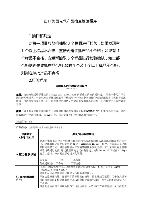
出口美国电气产品抽查检验程序
带有或不带有负载接口装置的并联连接季节性灯串产品应在火线上接 5A 保险丝
非极性串联连接季节性灯串产品,带有或不带有负载接口装置,应在火线和零线上同 时接 3A 保险丝。极性串联连接灯串产品如带负载接口应在未接地导线上接 5A 保险丝, 如不带负载接口应在未接地导线上接 3A 保险丝。
备注:
□合格 □不合格
B.通用电线组件 (2.10)
插头端: □合格
□不合格
负载适配端: □合格
□不合格
电线中的导体尺寸应与电线组件的额定电流相匹配,但是不能小于 18AWG
(1624cmil 或者 0.82mm2)
导体的面积由导线的直径决定(不接地和接地):
仔细去除导体绝缘,保证所有的导线没有损坏,数出导线的根数,用千分尺或等
或 14AWG 规线。
火线(黑):
平均直径:
截面积:
零线(白):
平均直径:
截面积:
接地线(绿):
平均直径:
截面积:
装有 14AWG(2.08 mm2)软线,带有 4 个到 6 个插座的移动式能量分配器(移
C.附加保护(13.1) 动式拖线板),以及带有7个或更多个插座的所有移动式能量分配器(移动式
拖线板),应提供过电流保护装置(OCP) □合格
电源延长线的检验评估程序
(2007 年 4 月)
范围:这些检验适用于连接到 15 或者 20A,120V,60Hz 的插座上的室内延长线, 即由一个两片平行 插片的两极插头、一定长度双导体组成的平行软线和一个带三个两极插座负载适配装置(也称导线连 接器)组成的室内延长线。对于包含其它结构特征的室内电线组件不在此列,比如带有三导体或者护 套线。
过电流保护应该是连接插头或电流分接头的完整部分,或者是直通软线结构(线上熔 丝座)的完整部分,连接插头或分接头的表面与熔丝座距连接插头或分接头最远侧面 之间距离不超过 6 英寸(152mm)。如采用直通软线结构,在连接插头或电流分接头与 熔丝座之间应使用最小规格为 20AWG(0.52mm2)的配线。
数据线出货检验作业指导书

数据线出货检验作业指导书-CAL-FENGHAI.-(YICAI)-Company One1五金头(TPC)尺寸符合图纸要求,电镀层光亮,不得有氧化、花斑、伤痕、锈蚀五金头(USB)尺寸符合图纸要求,表面应无划伤、流痕、毛刺、裂痕、无明显缩痕、拖花等成型缺陷及其它机械损伤。
线身印字清晰、无印字残缺(印字按客户要求),外观注塑完好,无批峰、无擦伤、线身无破皮、铜屑、裂纹、污点、条纹等。
注塑外形及尺寸符合图纸要求扎线扎线颜色及扎线方式符合图纸规格要求包装包装规格及数量依图纸要求检查图示电气性能导通1、按图纸线序摆位要求进行调试参数,依电性测试作业指导书进行抽检测试,并作好测试记录表。
2、用万用表进行线位点测确保线位准确性。
耐压测试将样品放置在温度为40±2℃,湿度为90-95%环境箱内48 小时后取出,在芯线与芯线之间、芯线与外被绝缘层之间,施加DC300V 的直流电压,漏电流设为0.5mA,测试时间为1 秒,导体电阻参照相应图纸。
判定标准:在规定时间内DC 输出线材应能经受高压测试而无飞弧或击穿等不良。
绝缘阻抗测试将样品放置在温度为40±2℃,湿度为90-95%环境箱内48 小时后取出,在芯线与芯线之间、芯线与外被绝缘层之间施加DC300V 的直流电压,时间保持1 分钟。
判定标准:其绝缘电阻应≥30 MΩ检验方法及判定标准机械性能摇摆试验线规测试部位及项目测试条件及判定标准1185SR 及DC/迈克线号24AWG22AWG20AWG18AWG16AWG 吊重200g 200g 250g 300g 400g/其它五金头摇摆试验摇摆角度±90°摇摆频率35 次来回/分钟判定标准摇摆3000 次后, 导通性良好,断线率≤30%2468SR 及DC/迈克/其它五金头摇摆试验线号24AWG22AWG20AWG18AWG16AWG吊重200g 200g 200g 300g 400g摇摆角度±60°摇摆频率30 次来回/分钟摇摆数次1000 1500 2000 2000 2000判定标准摇摆相应次数后, 导通性良好,断线率≤30%2464SR 及DC/迈克/其它五金头摇摆试验线号24AWG22AWG20AWG18AWG16AWG吊重200g250g300g400g500g摇摆角度±90°摇摆频率30 次来回/分钟判定标准摇摆2000 次后, 导通性良好,断线率≤30%非标线按图纸要求检验方法及判定标准机械性能摇摆试验插拔试验插头规格迈克头(安卓)迈克头(迷你)TPC(华为)DC头USB(A公)插拔次数5000 8000 10000 5000 1500插拔速度25次/分钟25次/分钟25次/分钟25次/分钟25次/分钟判定标准测试完后插拔力不少于初始插拔力的30%测试完后插拔力不少于初始插拔力的30%测试完后插拔力不少于初始插拔力的20%测试完后插拔力不少于初始插拔力的20%测试完后插拔力不少于初始插拔力的20% 试验设备插拢试验机检验方法及判定标准机械性能盐雾试验试验设备:盐雾试验机单条成型好的线材在无包装、非操作状态下,置于温度为 35-40℃盐雾试验箱内,持续喷雾规定时间,试验后取出样品,用清水冲洗、擦干,在室温下放置4 小时后,进行外观检查。
Lightning Tests Avionics Test System 产品说明书

AvionicsTest System ghtningTestsE s t a b l i s h e d19812Lightning Tests: Avionics Test SystemStudies by the Federal Aviation Administration (FAA) reveal that the average civil aircraft is struck by lightning every 1000 flight hours. It is therefore imperative that all aircraft should be tested to withstand the effects of lightning.Lightning events differ mainly in current amplitude, in the transferred charge and in the impulse shape of the lightning current. Two lightning events need to be simulated:− the direct strike (current and voltage) and− the induced currents and voltages within an aircraft resulting from a direct strike.Induced lightning current, voltage waveforms and impulse generator impedance values required to create these waveforms have been measured on avionic systems within aircraft subjected to direct strike events.Test standards including MIL-464 and DO-160 specify both direct and induced strike pulse sequences and levels. RTCA/DO-160 section 22 mandates that three sequences of pulses shall be used for induced lightning testing of avionics:- single stroke (SS),- multiple stroke (MS) and- multiple burst (MB).SS events are used for damage assessment on avionics subsystems and equipment. MS and MB events are applied to determine the electromagnetic compatibility of system, subsystems, and equipment. Multiple stroke and multiple burst events were specified for the first time in Revision 3 of DO-160 D; although they have been anticipated for a number of years and even recommended by the FAA Advisory Circular AC 20-136 and manufacturer specific testing protocols.In addition to the lightning induced transients, lower level transients caused by switching and other platform related phenomena are also a disturbance source within the avionic system. These phenomena are described in DO160 section 17, 19 and 25. For section 25 test equipment see our brochure “ESD Testers”.EMC PARTNER aircraft generators can replicate the following phenomena:- Multiple BurstThese pulses may result from lightning leader progression or branching. The pulses appear to be most intense at the time of initial leader attachment to the aircraft. Transient responses arising from the magnetic field of the external environment (component H) of the multiple burst waveform set will also occur in the induced multiple burst sequence. The predominant waveform responses are the damped sinusoidal waveform 3 in a frequency range between 1 to 10 MHz.- Multiple StrokeTypical lightning events include several high current strokes following the first re-turn stroke. These occur at intervals of several milliseconds as different pockets in the cloud feed their charge into the lightning channel. Another source is the swept channel process. If a fast moving aircraft experiences a direct strike, the points of arc attachment are likely to be swept backward along the aircraft since the lightning channel tends to remain stationary relative to the surrounding air.- Single StrokeSingle stroke events are used for damage assessment on avionic sub-systems and equipment. They can be divided into PIN injection and Cable bundle tests.PIN transients are applied directly to the system interface circuits and are used to assess the dielectric withstand voltage or damage tolerance of the interface com-ponents. Cable bundle tests are performed using an injection probe to couple tran-sients. Tests are performed on fully configured functioning equipment to determine equipment survivability.3Lightning Tests: Avionics Test System- Induced Signal SusceptibilityThese transients result from inductive switching and similar events within the installation, that are transmitted through interconnecting cables to an equipment interface.Such transients are mostly derived from the on-board power equipment and relate to the power supply frequencies and harmonics.- Voltage SpikeVoltage spikes can appear on the AC or DC power supply interfaces due to platform power supply switching transients. These are transmitted by interconnecting cables and appear at an equipment interface on the power supply pins. Disturbances on AC power lines could be synchronised to particular phase angles of the 400Hz supply.- Electrostatic DischargeThe low relative humidity and temperature in an aircraft together with extensive use of synthetic materials for floor and seat covering and plastic structures all contribute to the likelyhood of persons becoming electrostatically charged. Personnel can become charged to several tens of kilovolts. During normal operation or servicing, discharges from personnel could result in damage to electronic equipment.MIG0600SSMIG0600MS4Lightning Tests: Avionics Test System5Lightning Tests: Avionics Test SystemESD3000MIG2000-6MIG-OS-MB-EXTMIG-OS-MBMIG0618SS6Lightning Tests: Avionics Test System7Lightning Tests: Avionics Test System8Lightning Tests: Avionics Test System9Lightning Tests: Avionics Test System10Lightning Tests: Avionics Test System11Lightning Tests: Avionics Test SystemDN-LISN160-32NW-MS-LEVEL1I-PROBE-MSCN-GI-CICDN-BDBC13Lightning Tests: Avionics Test SystemCN-GI-CI-VCN-GI-CI-VCN-GI-CI-VCN-GI-CI-V2x CN-CI-V1 Array2x CN-CI-V1 + CN-CI-I114Lightning Tests: Avionics Test System15Lightning Tests: Avionics Test SystemCN-MIG-BTExample of a plug-inMIG-OS-MB-EXT16Lightning Tests: Avionics Test SystemAC-DC Decoupler Level 4 & 5I-PROBE-MB-P1CN-MIG-TTCN-MIG-BT3CN-MIG-BT117Lightning Tests: Avionics Test SystemRES10-400MRES20-400MCN-MIG-BT with three turned calibra-tion loopPredefined test routines for DO160For remote control of EMC PARTNER avionics generators, one of the following software packages is needed:- GENECS-MIG: This is a relatively simple program that reproduces generator front panel functions on a PC. In addition to remote programming and control of the gen-erators, test report information is available to word processing or other evaluation programs such as EXCEL.- TEMA Software: Comfortable control of EMC PARTNER generators from a PC.Enables several generator types to be included in the same test sequence. Gener-ates an enhanced level of test report.EMC PARTNER provide a FREE downloadable software which adds another dimension to testing. The DATABASE software is a high level program that provides hints and tips for users unfamiliar with avionics testing or the EMC PARTNER generators. Generator parameters are automatically downloaded into the corresponding instrument simply beselecting the test you wish to perfom.18Lightning Tests: Avionics Test System19Lightning Tests: Avionics Test System Hidden Heading to provoke a TOC entryLightning TestsA range of test equipment and accessories for aircraft, military and telecom applica-tions. Complete solutions including all hardware and software to meet the require-ments of RTCA / EUROCAE DO160 / ED14 for indirect lighting on aircraft systems,MIL-STD-461 tests CS106, CS115, CS116, for military vehicles, ITU-T .K44 basicrand enhanced tests for impulse, power contact and power induction, FCC part 68 fortelecom equipment testing.Component TestsModular impulse generat ors (MIG) for transient com ponent testing on: varistors, gasdischarge tubes (GDT), surge pro tective devices (SPD), X Y capacit ors, cir c uit breakers,watt-hour meters, protection relays, in sulation ma te rial, sup pressor di o des, connectors,chokes, fuses, resist ors, emc-gaskets, cables, etc. Manual or fully automated solutionsare available up to 100kA (8/20us) and 144kV (1.2/50us).Emission MeasurementsOne unit perf orms all measurements on the power sup plies of electronic equip m ent and r prod u cts for the CE-Mark. HAR1000 uses a novel techniques to deliver clean pow e r source for the EUT in a compact and lightweight form. The system includes all hardware A and software including line im p ed a nce net w orks, control and evaluation software. A basic 1-phase system can be easily extended to 3-phase by adding 2 further phases . HARCS Immunity soft w are further expands the system by addidng interharmonic tests, voltage variation and ripple on DC tests. Com p lies with IEC / EN 61000-3-2, -3 IEC / EN 61000-4-13, -14, Immunity TestsTransient Test System can be used to per f orms all EMC tests on elec t ron i c equip m ent. ESD, EFT, surge, AC dips, AC mag n et i c fi eld, surge mag n et i c fi eld, com m on mode, damped oscillatory and DC dips tests are available as stand-alone or combined test instruments. A large range of ac c es s o r ies for dif f er e nt ap p li c a t ions is avail a b le: three phase cou p lers up to 690V/100A, telecom and data line couplers, ver i fi c a t ion sets,magnetic fi eld coils. Immunity test systems fulfi lls IEC and EN 61000-4-2, -4, -5, -8, -9, -11, -12, -16, -18, -29.MIG2000-6 – a flexible solution for military andavionic applicationsMIG1212CAP – an automatic 8 bank capacitor test systemSystem AutomationAs addition to the basic generators, a range of accessories are available to enhance capability. Test cabinets, test pistols, adapters and software, simplify interfacing with the EUT.PS3 programmable source is an EMC hardened supply for frequencies form 16.7Hz to 400Hz. Frequency variation tests can be made using the PS3-SOFT-EXT. Complies with IEC / EN 61000-4-28HAR1000-3P and HARCS softwarea complete test systemPS3 - programmable source ideal for EMC applicationsTRA3000 and ESD3000 ideal for CE testing Easily extended to meet other applicationsFor further information please do not hesitate to contact EMC PARTNER’s representa-tive in your region. You will find a complete list of our representatives and a lot of otheruseful information on our website:The Headquarters in SwitzerlandEMC PARTNER AGBaselstrasse 160CH - 4242 LaufenSwitzerlandPhone: +41 61 775 20 30Fax: +41 61 775 20 59Email: sales@emc-partner.chWeb-Site: Your local representativeVersion 4. June 2010. Subject to change without notice.20Lightning Tests: Avionics Test System。
线缆测试流程英文版

线缆测试流程英文版Cable Testing Procedures.Introduction.Cable testing is a critical process in ensuring the reliability and performance of electrical systems. It involves verifying the electrical and physical characteristics of cables to ensure they meet the specified requirements and standards. This article provides a comprehensive overview of the cable testing procedures, including the different types of tests, equipment used, and interpretation of test results.Types of Cable Tests.There are several types of cable tests performed to evaluate different aspects of the cable:Continuity Test: Verifies the electrical continuity ofthe cable, ensuring that there are no breaks or interruptions in the conductor.Insulation Resistance Test: Measures the resistance between the conductor and the insulation, ensuring adequate electrical isolation and preventing current leakage.Hi-Pot Test (Dielectric Withstand Test): Applies a high voltage to the cable to test its dielectric strength and identify any weaknesses or insulation breakdowns.Time Domain Reflectometry (TDR): Uses a pulse generator to send a signal down the cable and analyze reflections to determine cable length, impedance, and any faults or discontinuities.Capacitance Test: Measures the capacitance of the cable to verify its ability to store electrical charge and ensure proper signal transmission.Inductance Test: Measures the inductance of the cable to determine its resistance to changes in current flow andits suitability for high-frequency applications.Attenuation Test: Assesses the signal loss over the length of the cable, ensuring that it meets the transmission requirements for the intended application.Return Loss Test: Evaluates the amount of signal reflected back from the cable, indicating impedance matching and minimizing signal distortion.Equipment for Cable Testing.Various equipment is used for cable testing, including:Multimeter: A versatile device that measures voltage, current, and resistance, used for continuity and insulation resistance tests.Megohmmeter: A specialized instrument that measures high resistance, used for insulation resistance tests.Hi-Pot Tester: A device that generates high voltagesfor dielectric withstand tests.Time Domain Reflectometer: A sophisticated instrument that uses pulse technology for TDR testing.Capacitance Meter: A device that measures the capacitance of cables.Inductance Meter: A device that measures the inductance of cables.Network Analyzer: A complex instrument that performs various cable tests, including attenuation and return loss measurements.Test Procedures.The specific test procedures vary depending on the type of test being performed. However, general guidelines for some common tests include:Continuity Test: Connect the multimeter to each end ofthe cable and measure the resistance. A low resistance reading indicates continuity.Insulation Resistance Test: Disconnect the cable from any power source and connect the megohmmeter between the conductor and the shield or ground. A high resistance reading indicates adequate insulation.Hi-Pot Test: Disconnect the cable from any power source and apply the specified voltage to the cable using the hi-pot tester. Monitor the leakage current and ensure it does not exceed the specified limits.TDR Test: Connect the TDR to one end of the cable and send a pulse down the cable. Analyze the reflected signal to determine cable length, impedance, and any faults.Capacitance Test: Connect the capacitance meter to the cable and measure the capacitance per unit length. Compare the measured value to the specified capacitance requirements.Inductance Test: Connect the inductance meter to the cable and measure the inductance per unit length. Comparethe measured value to the specified inductance requirements.Attenuation Test: Connect the network analyzer to the cable and transmit a signal at the desired frequency. Measure the signal loss over the length of the cable and compare it to the specified attenuation limits.Return Loss Test: Connect the network analyzer to the cable and measure the amount of signal reflected back from the cable. Compare the measured value to the specifiedreturn loss requirements.Interpretation of Test Results.The test results obtained from cable testing should be interpreted according to the relevant standards and specifications. Pass/fail criteria are typically definedfor each test, based on the intended application and safety requirements. Any deviations from the specified limits indicate potential issues with the cable and requirefurther investigation or corrective actions.Conclusion.Cable testing is a crucial aspect of electrical system maintenance and ensures the reliability, performance, and safety of electrical installations. By understanding the different types of cable tests, the equipment used, and the interpretation of test results, technicians and engineers can effectively evaluate the quality and integrity of cables, identify potential problems, and ensure the proper functioning of electrical systems.。
交直流电缆试验流程范本

交直流电缆试验流程范本英文回答:Testing procedures for AC/DC cable testing may vary depending on the specific requirements and standards set by the industry or organization conducting the test. However, I can provide a general outline of a typical testing process for AC/DC cables.1. Preparation: Before conducting the test, it is important to gather all the necessary equipment and ensure proper safety measures are in place. This includes wearing appropriate protective gear, such as gloves and goggles, and ensuring the testing area is clear of any potential hazards.2. Visual Inspection: The first step is to visually inspect the cable for any visible damage or defects. This includes checking for any signs of wear and tear, such as cracks or frayed wires. Any issues found during thisinspection should be noted and addressed before proceeding with the test.3. Insulation Resistance Test: The insulation resistance test is conducted to measure the resistance of the cable's insulation to electrical current. This test helps identify any potential insulation breakdown or leakage. It is typically performed using a megohmmeter or insulation resistance tester. The cable is disconnected from the power source and the tester is connected to the cable's conductors. The tester applies a high voltage to the cable and measures the resistance. A low resistance reading indicates a potential insulation problem.4. Dielectric Withstand Test: The dielectric withstand test is conducted to verify the cable's ability to withstand high voltage without breakdown or failure. This test is typically performed using a high voltage tester. The cable is connected to the tester and a high voltage is applied for a specified duration. The cable should be able to withstand the applied voltage without any issues.5. Partial Discharge Test: The partial discharge test is conducted to detect any partial discharges occurring within the cable's insulation. Partial discharges can be indicative of insulation defects or weaknesses. This test is typically performed using a partial discharge detector. The cable is connected to the detector and a high voltage is applied. The detector measures any partial discharges occurring within the cable.6. Voltage Withstand Test: The voltage withstand test is conducted to verify the cable's ability to withstand a specified voltage level without breakdown or failure. This test is typically performed using a high voltage tester. The cable is connected to the tester and a high voltage is applied for a specified duration. The cable should be able to withstand the applied voltage without any issues.7. Final Inspection: After completing the necessary tests, a final visual inspection is conducted to ensure the cable is in good condition and meets all the required standards. Any issues or defects found during this inspection should be addressed before the cable isconsidered safe for use.中文回答:交直流电缆试验的流程可能会因行业或组织的具体要求和标准而有所不同。
交直流电缆试验流程范本
交直流电缆试验流程范本英文回答:Testing Procedure for AC/DC Cable Testing.Testing electrical cables is an important process to ensure their safety and reliability. In this article, Iwill outline a sample testing procedure for AC/DC cables.1. Preparing for the Test.Before starting the test, it is essential to gather all the necessary equipment and materials. This includes the cable to be tested, a high voltage source, a ground connection, and appropriate measuring instruments such as a voltmeter and ammeter.2. Visual Inspection.Begin by visually inspecting the cable for any signs ofdamage, such as cuts, abrasions, or exposed wires. Also, check for proper insulation and ensure that all connectors are securely attached.3. Continuity Test.To test the continuity of the cable, connect one end of the cable to the ground and the other end to the high voltage source. Use a voltmeter to measure the voltage across the cable. If the voltage reading is zero or very low, it indicates good continuity.4. Insulation Resistance Test.Next, conduct an insulation resistance test to determine the integrity of the cable's insulation. Disconnect the cable from the ground and high voltage source. Connect one end of the cable to the ground and the other end to the voltmeter. Apply a high voltage to the cable and measure the insulation resistance. A high resistance reading indicates good insulation.5. Dielectric Withstand Test.The dielectric withstand test is performed to ensurethat the cable can withstand high voltage without breakdown. Connect one end of the cable to the ground and the otherend to the high voltage source. Gradually increase the voltage until it reaches the specified test value. Maintain the voltage for a predetermined time and monitor for any signs of breakdown or insulation failure.6. Current Leakage Test.To check for current leakage in the cable, connect one end of the cable to the ground and the other end to thehigh voltage source. Use an ammeter to measure the current flowing through the cable. A low or zero reading indicates no leakage, while a high reading suggests current leakage.7. Test Report.After completing the tests, record all the relevantdata and observations in a test report. Include detailssuch as the test date, cable specifications, test equipment used, test results, and any abnormalities observed during the testing process.中文回答:交直流电缆试验流程范本。
手持式链锯类产品开发测试流程

手持式链锯类产品开发测试流程下载温馨提示:该文档是我店铺精心编制而成,希望大家下载以后,能够帮助大家解决实际的问题。
文档下载后可定制随意修改,请根据实际需要进行相应的调整和使用,谢谢!并且,本店铺为大家提供各种各样类型的实用资料,如教育随笔、日记赏析、句子摘抄、古诗大全、经典美文、话题作文、工作总结、词语解析、文案摘录、其他资料等等,如想了解不同资料格式和写法,敬请关注!Download tips: This document is carefully compiled by theeditor. I hope that after you download them,they can help yousolve practical problems. The document can be customized andmodified after downloading,please adjust and use it according toactual needs, thank you!In addition, our shop provides you with various types ofpractical materials,such as educational essays, diaryappreciation,sentence excerpts,ancient poems,classic articles,topic composition,work summary,word parsing,copy excerpts,other materials and so on,want to know different data formats andwriting methods,please pay attention!1. 需求分析:确定产品的目标市场和用户群体。
收集用户需求和反馈,了解他们对链锯性能、功能、安全性等方面的期望。
引线组件检验规程
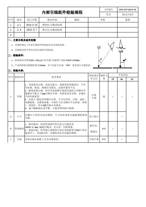
项目
抽样水平 不合格分类及合格质量水平
外观
II
尺寸/性能测试/实装
S-2
CR:0 MA:1.0 MI:2.5
四、执行方法:
IQC检验后对产品做好相应标识,并做好检验记录。
HYQ-SIP-Q003-05 第2页共2页 批准
不良判定
MA
MI
√
√
目视手感 S-2
√
内部引线组件检验规程
文件编号 页次
序号 版本 发行日期
修改内容
编制
审核
2 2.0 2023/3/7 修正拉力测试标准
序号 检验项目
技术要求
检验要求 抽样方
及方法 案
CR
端子铆压牢固度,必须通过拉力测试(测试前要将卡在线皮
上的扣子撬开):
a. 单根导线时,将端子固定,缓慢拉伸导线,在规定拉
16AWG(1.31mm2):133.5 N;
1.5mm2:150N;
b. 多根导线时,将最粗的导线固定,缓慢拉伸最细的导 拉力计
5 端子拉力 线,在规定拉力下保持1分钟。接着按照导线粗细从小到大
秒表
S-2
分别在规定拉力下保持1分钟。导线不脱开,断丝不超过5%
或有其他损伤。
端子拉力与线芯尺寸对应为:
2、产品和检验员眼睛距离为300mm,从产品前方以45°和90°角度进行目视检查。 三、检验内容:
序号 检验项目
技术要求
检验要求 抽样方
及方法 案
CR
1、导线使用正确,表面无脏污,热缩套管热缩到位,不许
有松散、脱落,绝缘层无破皮,金属外露等不良。
2、配线连接正确,氖灯同电阻铆压线段同线段之间铆压外
露铜丝不能大于2mm且铆压牢固,弯曲套管处导线,金属丝
线束组件测试要求
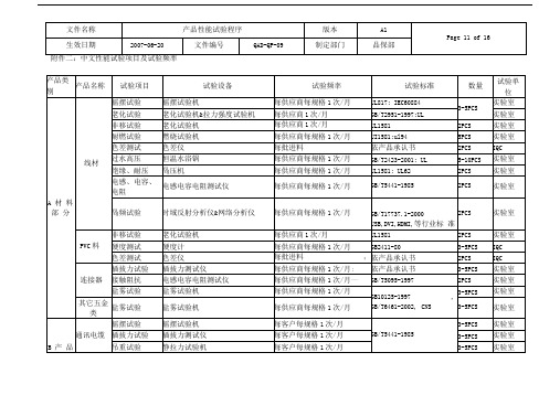
每客户每规格
1次/月
3-5PCS
实验室
铅珠试验
铅珠&高压机
每客户每规格
1次/月
3-5PCS
实验室
摇摆试验
摇摆试验机
每客户每规格
1次/月
3-5PCS
实验室
其它产品
插拔力试验
插拔力测试仪
每客户每规格
1次/月
依客户要求
3-5PCS
实验室
接触阻抗
电感电容电阻测试仪
每客户每规格
1次/月
3-5PCS
每供应商每规格1次/月:
依产品承认书
3-5PCS
实验室
接触阻抗
电感电容电阻测试仪
每供应商每规格1次/月—
GB/T5095-1997
2PCS
实验室
盐雾试验
盐雾试验机
每供应商每规格1次/月
GB10125-1997,
GB/T6461-2002,CNS
3-5PCS
实验室
其它五金 类
盐雾试验
盐雾试验机
每供应商每规格1次/月
A
Materia
l part
Cable
Bending test
Bending tester
On etime per month for each supplier and P/N
IUL817;
IEC60884
3-5PCS
Laboratory
Agi ng test
Aging tester&pull
inten sity tester
voltage
high voltage tester
On etime per month for each supplier and P/N
Cable 信赖性测试规范(XJ)
TITLE 標準書名稱旭基(麗)電子有限公司PAGE NO.頁碼2/9TITLE Cable reliability test standard INITIA TED DATE制定日期2007/04/05標準書名稱Cable 信賴性測試規范REVISED DA TE修定日期N/A5.1.4品質重點1) 測試的角度的120 度, 測試速度: 30次/分, 荷重: 300g2) 總測試次數為: 3000 次3) 測試時, cable 通0.1 A 的直流電流4)测试完毕,再进行高压、绝缘测试(测试标准请参考环测高压绝缘测试项目)4) 測試完畢, 剝開絕緣皮, 確認有多少根線開路5.2 Cable 插入及拔出力測試(Sample size: 2pcs)5.2.1測試前檢查項目: N/A5.2.2測試方法及步驟:1) 把Cable以12.5mm/min的速度,慢慢插入母座中,记录压力计读数2) 用拉力計以12.5mm/min的速度,慢慢把Cable 線拔出, 記錄這時拉力計的讀數.5.2.3 測試后檢查項目及判定標準:1:USB1) 插入力:小于3.5 Kg2)拔出力:大于1Kg2:PS21) 插入力:小于 4.5 Kg2)拔出力:大于0.9Kg5.2.4品質重點:1) 每项測試十次, 求平均值.5.3 Cable 插入壽命測試(Sample size: 1pcs)5.3.1測試前檢查項目:1) Cable接觸阻抗2) Cable 拔出力5.3.2測試方法及步驟:1) 固定Cable 線在測試治具上旭基(麗)電子有限公司PAGE NO.頁碼3/9TITLE Cable reliability test standard INITIA TED DATE制定日期2007/04/05標準書名稱Cable 信賴性測試規范REVISED DA TE修定日期N/A2) 設定測試次數3) 開啟電源5.3.3 測試后檢查項目及判定標準:1) Cable接觸阻抗: 變化率小於或等於35%2) Cable 拔出力: 變化率小於或等於35%5.3.4品質重點1) 測試次數: PS/2 線: 1000 次; USB 線: 1500次2) 測試速度: 200次/H,pull-out Max speed:12.5mm/min5.4 Cable 插頭強度測試(Sample size: 2pcs)(暂测USB cable)5.4.1 測試前檢查項目:1) Cable 導通及開路測試5.4.2 測試方法及步驟:1) 把Cable 插入母座中2) 用推力計壓Cable 頭處: 5Kg, 30 秒5.4.3測試后檢查項目及判定標準:1) Cable 導通及開路測試: 測試pass2) Cable 頭的外觀: 不允許有裂痕及插頭鬆動, 變形.5.4.4品質重點:1) 施力點: 在Cable 頭的未端5.5 Cable 拉力強度測試(Sample size: 2pcs)旭基(麗)電子有限公司PAGE NO.頁碼4/9TITLE Cable reliability test standard INITIA TED DATE制定日期2007/04/05標準書名稱Cable 信賴性測試規范REVISED DA TE修定日期N/A5.5.1 測試前檢查項目:1) Cable 導通及開路測試5.5.2 測試方法及步驟:1) 固定Cable2) 施加5Kg 力,00,+/-450,各1分鐘(如果客户有要求,这以客户spec为标准)5.5.3測試后檢查項目及判定標準:1) Cable 導通及開路測試: 測試pass2) Cable 外觀: 不允許有裂痕或絕緣皮損傷5.5.4品質重點: N/A5.6 Cable connect side pull test(Sample size: 2pcs)5.5.1 測試前檢查項目:1) Cable 導通及開路測試2)高压、绝缘测试5.5.2 測試方法及步驟:1) 将cable 插入固定的母座中2)于USB connentor 水平900方向,距connector 100mm的地方固定拉力计3) 用拉力计以2Kg拉力,水平保持30s的时间。
耳机线材出货检查标准书

各种规格的耳机线材检查顺序缺点区分6MAMA MI 10CR 11CR NO 实施日作成确认承认1.有效保护产品,便于运输和储藏检查是否使用完好的新纸箱,纸箱内有无围卡和隔层的平卡,有无颜料袋包装作成日期:2012-6-18改订内容检查标准书上规定检查的数量时 按标准书检测。
※工程提出资料:有( ● ), 无( )MODEL NOAQL■ 一般检查水准 (Ⅱ)※ 检查项目按检查水准来、Sampling 检查,测定data 10pcs 以上时 成绩书上记录 10pcs 品名线 材检 查 方 法个数 Sampling G-Ⅱ[改订履历] 长度7依据图面,在客户允许的公差范围之内依据图面,在客户允许的公差范围之内1>百分表测量外径2>内径用针规测量3>空管用针规测量之外,还需要试穿1>颜色需要比对客户承认的样品,不得有色差电阻MI电阻机精密线材综合测试仪MA 钢尺测量,结果记录于报表上;轴装的总长度与标示一致改订编号MA2>目视:有无鼓包,有无起颗粒,有无压痕刮伤,有无脏污等使用脱皮机, 脱皮后检查规格、颜色、数量1>半中空式线材,脱皮30-40mm,能轻松拽落外皮2>实芯押出线材,脱皮10-15mm,拽落外皮时手感不偏于太松或太紧MA 3>客户有特殊规定的依据客户要求实施MI核对胶料袋上的标识小刀切割后,观察横截面,芯线周围的外皮厚度均匀一致,必要时使用放大镜检查脱皮的松紧程度绝缘阻抗 1 Ω/m以内 DC 250V 1MIN, 10M Ω以上9MA 偏心检查偏心度10%以内1中心线2芯线构成,数量、颜色、绝缘胶料,导体表面完好程度TECHNORA/POLYESTER/KEVLAR,3种中心线,依据客户要求使用12包装外被料缠绕丝的规格、颜色、数量品番、规格型号、厂家信息、LOT号检查项目芯线导体MA CR目视,依据图面和比对样品.检查方法内容与基准目视:TECHNORA的颜色为暗黄色,POLYESTER的颜色为白色,KEVLAR为鲜黄色CR :0 MA :0.4 MI :0.65外观85脱皮检查3缠绕丝无外观不良外径/内径4线材出货检查标准书B唐文勇朴并林12.06.18作成确认承认。
Cable线材成品检验规范
文件制修订记录
1、目的:
规范Cable线材物料检验,保证产品质量。
2、适用范围
适用IQC所有来料Cable线材物料检验。
3、参照文件:
本作业规范参照本公司程序文件《进料检验管理办法》、《抽样计划作业办法》、《图面》以及相关可靠性试验技术标准、设计参数资料.
4、规范内容:
4.1测试工量具及仪表:卷尺、钢尺、OD表、千分尺、电测机、卡尺等。
4.2缺陷分类及定义:
致命缺陷(CR=0):单位产品的安全特性不符合规定, 有可能造成顾客生命财产安全之缺陷。
主要缺陷(MAJ=025):单位产品的重要质量特性不符合规定,或者单位产品的质量特性严重不符合规定。
轻微缺陷(MI=0.65):单位产品的一般质量特性不符合规定,或者单位产品的质量特性轻微不符合规定。
5、检验项目和技术要求:
具体抽样数量参考《抽样标准指引》。
《IQC进料检验记录表》《进料收货单》。
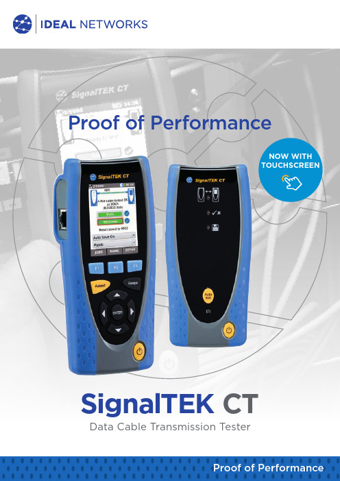
SignalTEK CT 数据电缆传输测试仪性能证明说明书
SignalTEK CT Data Cable Transmission TesterProof of PerformanceProof of PerformanceNOW WITH TOUCHSCREENSignalTEK CTData Cable T ransmission T esterProof of Performance If you install or maintain data cabling, SignalTEK CT allows you to generate PDF test reports that prove installed links run at Gigabit Ethernet transmission rates.For installers, this means having a cost-effective way to demonstrate that the copper cabling was installed correctly and is capable of supporting Ethernet applications. By proving real world performance, SignalTEK CT confirms a professional job - reducing the risk of call backs. SignalTEK CT also gives network owners the assurance that installed cabling will support bandwidth hungry services like VoIP, IP CCTV andvideo streaming following moves, adds and changes.Today’s challengeThe foundation of all Ethernet networks is the physical cabling. As networks become faster and more complex they become more susceptible to disruption from external interference as well as faulty cabling and or connectors. These physical layer problems can cause a high number of server re-transmissions resulting in network drop-out or slow connection speeds.If network performance issues are to be avoided, today’s installers and techniciansneed test equipment that not only verifies correct wiring but also confirms a link’s ability to transmit data at full rate.Tomorrow‘s solutionUniquely SignalTEK CT proves a link’s ability to support Gigabit applications by performing two primary tests; data transmission and wiremap testing . With a single press of the Autotest button, SignalTEK CT transmits 823,452 data frames between the two handsets and reports any transmission errors against performance criteria laid down by the IEEE 802.3ab Gigabit Ethernet Standard. It takes only 1 bit of data to get corrupted or lost to give rise to a transmission test failure.Autotest also measures cable length and checks for wiring faults such as crossedpairs, opens, shorts and split pairs.Simple pass/fail results are displayed once the Autotest is complete which can beautomatically saved for later review or download.Autotest from remote unitfor one person testing Replaceable RJ45 contacts• A utomatic generation of PDF format test reports makes documentation effortless • U ser-friendly menu structure for trouble-free operation and minimal training• S imple cable naming and job creation enhances on-site productivityDependable• T ests against IEEE802.3ab to assure cable performance against a recognisedinternational standard• F ield replaceable RJ45 contacts eliminate downtime from worn or damaged connectors • R ugged design provides protection against knocks in the field• N o requirement for annual calibration reducing cost of ownershipData test results screen Wiremap results screenOrdering InformationOptional AccessoriesBasic SpecificationsData Cable Transmission TesterProof of PerformanceSignalTEK CTIDEAL INDUSTRIES Networks Ltd.Stokenchurch House, Oxford Road, Stokenchurch,High Wycombe, Bucks, HP14 3SX, UK.Tel. +44 (0)1925 428 380 | Fax. +44 (0)1925 428 381******************** A subsidiary of IDEAL INDUSTRIES INC.Specification subject to change without notice. E&OE Printed in UK.© IDEAL Networks 2018Publication no. 156858 Rev For detailed specifications, please visit .SignalTEK-CT Test Report PASS Test ReportingSignalTEK CT automatically generates test reports in PDF or CSV format. The summary page of each report can be customised to include logo, company and operator details. Choose between 2 different reports that can show either passed, failed or all test reports in each report: • Summary• Full (see example on the right side)Apple and the Apple logo are trademarks of Apple Inc., registered in the U.S. and other countries. App Store is a service mark of Apple Inc.Android is a trademark of Google Inc.All Rights Reserved. IDEAL, IDEAL NETWORKS and the SignalTEK logos are trademarks or registered trademarks of IDEAL INDUSTRIES, INC.。
数据线测试项目及技术要求

测试方法:在所有接触脚之间及接触脚与塑料基座之间测量。
测试条件:电压350V(50/60Hz,截止电流2mA)时间1分钟
判定方法:无击穿或电火花现象发生,功能正常。
振动试验
试验方法:将数据线与手机及电脑连接好,手机及数据线固定在振动测试仪上,在通电状态下进行测试。
测试条件:频率10-55-10Hz/分钟振幅1.8mm方向X.Y.Z试验时间2小时x 3轴共6小时
数据线测试项目及技术要求
测试项目
技术要求
外观
数据线塑胶表面无划伤、脏污、缩水、流纹等;连接器PIN针无氧化、刮伤、变形;线材表面不能有刮伤、异色等缺陷。
工艺及装配
数据线配合手机及电脑接口后要求无错位、松动、接触不良等现象。
数据线引线要焊接可靠,预留一定的防拉伸距离。
各批量试用时的工程不良率不能超过5000 PPM规定值。
180cm跌落到置于水泥地面上的18mm-20mm厚的硬木板上(6面42次),4小时后测量电芯电压应正常,无漏液、冒烟、发热等现象。
30cm重复跌落到硬木板台面(6面60次),电池应能正常充放电。
正弦振动
10~55Hz扫频,XYZ每个面扫频10次,速率1oct/min;
10~30Hz:0.38mm,30~55Hz:0.19mm;
加工工艺
开壳测试
拆开外壳观察保护板焊接质量,不应有元件短路、虚焊、脱焊、极耳处点焊有无过深过浅等现象,电池内部布局应合理、电芯应有标明规格参数、PCB板整洁干净、版本号清晰、双面胶粘贴可靠、成“L”型分布或能够达到水平、竖直方向都有固定的分布方式。
金属镀层测试
PCB板镀层测试
对电池的五金端子进行24小时盐雾试验以及镀层厚度测试,端子应无氧化生锈现象。
- 1、下载文档前请自行甄别文档内容的完整性,平台不提供额外的编辑、内容补充、找答案等附加服务。
- 2、"仅部分预览"的文档,不可在线预览部分如存在完整性等问题,可反馈申请退款(可完整预览的文档不适用该条件!)。
- 3、如文档侵犯您的权益,请联系客服反馈,我们会尽快为您处理(人工客服工作时间:9:00-18:30)。
Power Supply
digital multimeter
MFI USB breakout VBUS MFI USB breakout board RCPT_P_IN
GND
GND
Power Supply
digital multimeter
MFI USB breakout VBUS MFI USB breakout board Rghtning (Cxx) Current Limit Test
Test setup : USB breakout : USB receptacle 的轉接板, MFi Lightning Breakout : 有Lightning Receptacle的轉接板 有USB type-A connector 的cable,接在MFI USB breakout之後再與電源供應器連接. 沒有USB type-A connector 的線材, 先將電源線焊接在MFI USB breakout board 上, 再連接到電源供 應器. 設定電源供應器最小電流值為20mA. Cable lightning plug 連接到 MFi Lightning Breakout, 電流表串接在RCPT_P_IN 上量測電流. 電源供應器5.0V 連接一個3.5V的電池負載, 在RCPT_P_IN and GND, 量測電流值. Current must be < 8mA. RCPT_P_IN and GND短路,Current must not exceed 15mA.
Lightning (Cxx) Over Voltage Protection Test
Test setup : USB breakout : USB 連接器的轉接板 有USB type‐A connector 的cable,接在MFI USB breakout之後再與電源供應器連接. 沒有USB type‐A connector 的線材, 先將電源線焊接在MFI USB breakout board 上, 再連接到電源供應器. Cable lightning plug 連接到 MFi Lightning Breakout, 電壓表在RCPT_P_IN and GND兩點量測電壓. 電源供應器先供給5.0V後, 再調高到9.0V 觀察輸出端VBUS的電壓在6.0V ~ 6.6V 期間內, P_IN的電壓值須保持為0V.
Power Supply digital multimeter
MFI USB breakout MFI USB breakout board VBUS RCPT_P_IN Load 3.5V
GND
GND
Lightning (Cxx) Quiescent Current Consumption Test
Test setup : USB breakout : USB 連接器的轉接板, MFi Lightning Breakout : 有Lightning Receptacle的轉接板 有USB type-A connector 的cable,接在MFI USB breakout之後再與電源供應器連接. 沒有USB type-A connector 的線材, 先將電源線焊接在MFI USB breakout board 上, 再連接到電源供應器. Cable lightning plug 連接到 MFi Lightning Breakout, 電流表串接在VBUS 上量測電流. 電源供應器設定電壓為 -1V, Current must not exceed 17mA 電源供應器設定電壓為 5V, Current must not exceed 1mA
