FAR-F5KA-881M50-D4DB-Z;中文规格书,Datasheet资料
FAR-G5CN-942M50-D296-Y中文资料

4
8
4
7
6
5 7 6 5
s PIN DESCRIPTIONS
• 1 in/2 out type Pin Pin name 1 2 3 4 5 6 7 8 IN GND GND GND OUT GND OUT GND Description Input Pin (Common) Ground Pin Ground Pin Ground Pin Filter 2 Output Pin Ground Pin Filter 1 Output Pin Ground Pin
2
元器件交易网
G5/G6 Series
s INTERNAL BLOCK DIAGRAM
1 in/2 out type 2 in/2 out type
1
BPF1
7
1
BPF1
7
BPF2
5
3ቤተ መጻሕፍቲ ባይዱ
BPF2
5
1
−
7 : Pin number
3
元器件交易网
15
5
FAR-G6CH-1G7475-L216
16
6
FAR-G6CH-1G8425-L217
17
7
FAR-G6CH-1G8425-L218
EGSM + PCN Rx 1805 MHz to 1880 MHz 925 MHz to 960 MHz 1805 MHz to 1880 MHz 925 MHz to 960 MHz 1805 MHz to 1880 MHz 925 MHz to 960 MHz 1930 MHz to 1990 MHz 1805 MHz to 1880 MHz 1930 MHz to 1990 MHz 1850 MHz to 1880 MHz 1880 MHz to 1910 MHz 1930 MHz to 1960 MHz 1960 MHz to 1990 MHz
FLD5F15CA-N9010中文资料

2
元器件交易网
Tunable LD Module with
Wavelength Locker
FLD5F15CA-N
Figure 1 Wavelength Table
Part Number
FLD5F15CA-N9090 FLD5F15CA-N9085 FLD5F15CA-N9050 FLD5F15CA-N9045 FLD5F15CA-N9010 FLD5F15CA-N9005 FLD5F15CA-N8970 FLD5F15CA-N8965 FLD5F15CA-N8930 FLD5F15CA-N8925 FLD5F15CA-N8890
IF
Photodiode Reverse Voltage
VDR
Photodiode Forward Current
IPF
Cooler Current
Ic
Cooler Voltage
Vc
Condition -
CW -
CW -
Ratings
Unit
-40 to +85
°C
0 to +70
°C
30
mW
2
V
PIN-PDs (InGaAs), Power Monitor PIN • Polarization preserving (PANDA) fiber
APPLICATIONS:
Long haul DWDM Metropolitan DWDM Optical Test Equipment
DESCRIPTION:
元器件交易网
Tunable LD Module with
Wavelength Locker
FLD5F15CA-N
FLUKE8808A说明书

?2007 年 7 月? 2007 Fluke Corporation,保留所有权利。
所有的产品名称均为相应所有人的商标。
.8808A 数字万用表 用户手册Байду номын сангаас
LIMITED WARRANTY AND LIMITATION OF LIABILITYEach Fluke product is warranted to be free from defects in material and workmanship under normal use and service. The warranty period is one year and begins on the date of shipment. Parts, product repairs, and services are warranted for 90 days. This warranty extends only to the original buyer or end-user customer of a Fluke authorized reseller, and does not apply to fuses, disposable batteries, or to any product which, in Fluke's opinion, has been misused, altered, neglected, contaminated, or damaged by accident or abnormal conditions of operation or handling. Fluke warrants that software will operate substantially in accordance with its functional specifications for 90 days and that it has been properly recorded on non-defective media. Fluke does not warrant that software will be error free or operate without interruption.Fluke authorized resellers shall extend this warranty on new and unused products to end-user customers only but have no authority to extend a greater or different warranty on behalf of Fluke. Warranty support is available only if product is purchased through a Fluke authorized sales outlet or Buyer has paid the applicable international price. Fluke reserves the right to invoice Buyer for importation costs of repair/replacement parts when product purchased in one country is submitted for repair in another country.Fluke's warranty obligation is limited, at Fluke's option, to refund of the purchase price, free of charge repair, or replacement of a defective product which is returned to a Fluke authorized service center within the warranty period.To obtain warranty service, contact your nearest Fluke authorized service center to obtain return authorization information, then send the product to that service center, with a description of the difficulty, postage and insurance prepaid (FOB Destination). Fluke assumes no risk for damage in transit. Following warranty repair, the product will be returned to Buyer, transportation prepaid (FOB Destination). If Fluke determines that failure was caused by neglect, misuse, contamination, alteration, accident, or abnormal condition of operation or handling, including overvoltage failures caused by use outside the product’s specified rating, or normal wear and tear of mechanical components, Fluke will provide an estimate of repair costs and obtain authorization before commencing the work. Following repair, the product will be returned to the Buyer transportation prepaid and the Buyer will be billed for the repair and return transportation charges (FOB Shipping Point).THIS WARRANTY IS BUYER'S SOLE AND EXCLUSIVE REMEDY AND IS IN LIEU OF ALL OTHER WARRANTIES, EXPRESS OR IMPLIED, INCLUDING BUT NOT LIMITED TO ANY IMPLIED WARRANTY OF MERCHANTABILITY OR FITNESS FOR A PARTICULAR PURPOSE. FLUKE SHALL NOT BE LIABLE FOR ANY SPECIAL, INDIRECT, INCIDENTAL, OR CONSEQUENTIAL DAMAGES OR LOSSES, INCLUDING LOSS OF DATA, ARISING FROM ANY CAUSE OR THEORY.Since some countries or states do not allow limitation of the term of an implied warranty, or exclusion or limitation of incidental or consequential damages, the limitations and exclusions of this warranty may not apply to every buyer. If any provision of this Warranty is held invalid or unenforceable by a court or other decision-maker of competent jurisdiction, such holding will not affect the validity or enforceability of any other provision.Fluke Corporation P.O. Box 9090 Everett, WA 98206-9090 U.S.A.Fluke Europe B.V. P.O. Box 1186 5602 BD Eindhoven The Netherlands11/99To register your product online, visit
法国尚飞RTS样本产品手册
Silver Lounge 银色
Black 黑色
02
Cherry 樱桃木色
Walnut 胡桃木色
兼容各种电动窗饰及门窗系统
垂直开启
卷帘,百叶窗,遮阳篷,室内帘,爬升式车库门
水平开启
开合帘,双开式庭院门
Somfy独有
上行 停止或运行到中间位置 下行
开启 停止或运行到中间位置 关闭
中间位置功能
上,下限位中的任意位置可被设定为中间位置。在电 动窗饰产品静止时,按“my”键,窗饰产品将直接运 行到预设的中间位置,该功能非常适合窗饰的齐平 管理系统
北京 (北区) 北京朝阳区东大桥路8号 SOHO尚都北塔A楼1105室 邮编:100020 电话:(86-10) 5900 2254 传真:(86-10) 5900 0274
成都 (西区) 四川省成都市鼓楼南街1 号 四川国际大厦C区6楼C-D座 邮编:610016 电话:(86-28) 8652 1434 传真:(86-28) 8652 1431
Smoove触控系统
Smoove 1 RTS -控制1个或1组RTS产品 -80X80mm外框
Pure Shine 亮白
Black Shine 亮黑
Silver Shine 亮银
无线技术
Red Light 亮红
Smoove 1 Open/Close -控制1个或1组水平开合RTS产品 -80X80mm外框
触控技术 Smoove将目前最先进、最 流行的触控技术,应用到 墙面开关的控制上
清晰的互动 当您触控开关进行任何一种操作 时,开关的LED指示灯会闪烁, 并发出“bi”的操作提示音
开关与外框组合搭配,适合各种装饰风格
Smoove 4种不同涂装的开关模块
KA5M0365RTU;KA5M0380RYDTU;KA5L0380RYDTU;KA5H0365RTU;KA5M0365RYDTU;中文规格书,Datasheet资料

Operating Junction Temperature. Operating Ambient Temperature. Storage Temperature Range.
Symbol
VDGR VGS IDM
ID ID EAS VCC,MAX VFB PD Derating TJ TA TSTG
VDGR VGS IDM
ID ID EAS VCC,MAX VFB PD Derating TJ TA TSTG
Note: 1. Repetitive rating: Pulse width limited by maximum junction temperature 2. L = 51mH, starting Tj = 25°C 3. L = 13μH, starting Tj = 25°C
Absolute Maximum Ratings
(Ta=25°C, unless otherwise specified)
Characteristic KA5H0365R, KA5M0365R, KA5L0365R Drain-Gate Voltage (RGS=1MΩ) Gate-Source (GND) Voltage Drain Current Pulsed (1) Continuous Drain Current (TC=25°C) Continuous Drain Current (TC=100°C) Single Pulsed Avalanche Energy (2) Maximum Supply Voltage Analog Input Voltage Range
KA5x03xx-SERIES
KA5H0365R, KA5M0365R, KA5L0365R KA5H0380R, KA5M0380R, KA5L0380R Fairchild Power Switch(FPS)
凯瑞兹GL4战术手电说明书
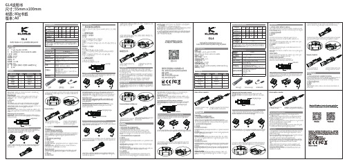
GL4说明书尺寸:55mm x100mm 材质:80g书纸Remote Switch深圳市龙岗区坂田街道龙景科技园E栋8楼518000 400-631-0169***********************深圳市凯瑞兹电子科技有限公司微信公众号静态电流战术鼠尾战术导轨夹战术灯Tactical rail clamp Tactical light ALLUMÉ/ÉTEINTb) ExtérieurOperación del interruptor remotoInterruptor principal: presione para encender y apagar (salida turbo)Interruptor de modo: mantén presionado para salida Turbo, suéltalo para apagar.Interruptor principalInterruptor de modoOpération:1) Commutateur de paramètres (la valeur par défaut est tactique)Depuis OFF, appuyez et maintenez enfoncé le commutateur MODE pendant 5 secondes. Appuyez sur le commutateur MAIN sans relâcher le commutateur MODE lorsque le voyant clignote en rouge/vert pour basculer entre les réglages2) Opération de paramétrage a) Tactique ALLUMÉ/ÉTEINTInterrupteur PRINCIPAL : appuyez pour allumer à HAUT, appuyez à nouveau pour éteindreCommutateur MODE : appuyez pour allumer le STROBED, maintenez-le enfoncé pendant 2 secondes pour LOCK STROBECommutateur MODE : appuyez pour changer la sortie Turbo->High->Medi-um->Low->Cycle. Appuyez et maintenez pendant 2 secondes pour entrer STROBEFernschalter:3.Um das Licht vom Adapter zu entfernen, drehen Sie den Verriegelungsknopf am Adapter leicht, um den Adapter zu lösen, und schieben Sie dann das Licht vom Adapter weg.1.Lösen und entfernen Sie dieEndkappe gegen den Uhrzeigersinn2.bringen Sie die Endkappe des Fernschalters an der Leuchte an und testen Sie die Funktion.1Método de instalación del producto1.Afloje los tornillos del adaptador de riel con la llave hexagonal incluida, alinee el adaptador con el riel del arma de fuego y apriete los tornillos para bloquear el adaptador en los rieles del arma de fuego.232.Inserte el conector de la luz en los rieles del adaptador hasta que se escuche un "clic", esto indica que la luz y el adaptador se han conectado de forma segura.3.Para quitar la luz del adaptador, gire ligeramente el botón de bloqueo en el adaptador para aflojar el adaptador, luego deslice la luz lejos del adaptador.Modes de sortie :。
淡水红外感应LED驱动器测试板说明书

and please deal with it after confirming such electric discharge.
4ch White LED Driver Built-in Current Driver
Boost DC/DC Converter for Automotive
BD83A24MUF-M Evaluation Board
REFLED005-EVK-002
Introduction
This user’s guide will provide the necessary steps to operate the Evaluation Board of ROHM’s BD83A24MUF-M LED Driver.
During Use
[5] Be careful to not allow conductive objects to come into contact with the board.
[6] Brief accidental contact or even bringing your hand close to the board may result in
should by handled only by qualified personnel familiar with all safety and operating
procedures.
We recommend carrying out operation in a safe environment that includes the use of high
科尔摩根AKM 同步伺服电机 选型指南说明书

K O L L M O R G E N | A K o l l m o r g e n C O M PA N Y欢迎来到科尔摩根官方微信科尔摩根3目录u AKM ™ 同步伺服电机4u AKD ™ 伺服驱动器8u AKM ™ 各种选件12u AKM ™ 防水型和食品级防水型电机13u AKM ™ 系统综述14u AKM ™ 图纸和性能数据AKM1x 16AKM2x 20AKM3x24AKM4x 28AKM5x 34AKM6x 40AKM7x 44AKM8x48u L 10 轴承疲劳寿命和轴负载53u 反馈选件56u 抱闸选件60u 伺服电机连接器选件61u 型号命名67u MOTIONEERING ® Online71科尔摩根A K M 同步伺服电机选型指南克服设计、采购和时间障碍科尔摩根明白:帮助原始设备制造商的工程师克服障碍,可以显著提高其工作成效。
因而,我们主要通过如下三种方式来提供帮助:集成标准和定制产品在很多情况下,理想方案都不是一成不变的。
我们拥有专业应用知识,可以根据全面的产品组合来修改标准产品或开发全定制解决方案,从而为设计奠定良好的基础。
提供运动控制解决方案而不仅仅是部件在各公司减少供应商数量和工程人力的过程中,他们需要一家能够提供多种集成解决方案的全系统供应商。
科尔摩根就采用了全面响应模式,为客户提供全套解决方案,这些方案将编程软件、工程服务以及同类优秀的运动控制部件结合起来。
覆盖全球我们在美洲、欧洲、中东和亚洲拥有众多直销、工程支持单位、生产工厂以及分销商,临近全球各地的原始设备制造商。
这种便利优势可以加速我们的供货过程,根据客户需要随时随地供货。
财务和运营稳定性科尔摩根隶属于Fortive 公司。
Fortive 业务系统是推动Fortive 各部门发展的一个关键力量。
该系统采用“不断改善”(Kaizen )原理。
由高素质人才构成的多学科团队使用世界级的工具对过程进行评估,并制定相关计划以达到卓越的性能。
聚英翱翔DAM0404继电器控制卡说明书

DAM0404D继电器控制卡说明书V1.1北京聚英翱翔电子有限责任公司2015年01月目录一、产品特点 (3)二、产品功能 (3)三、产品选型 (3)四、主要参数 (3)五、接口说明 (4)六、通讯接线说明 (5)1、RS485级联接线方式 (5)七、输入输出接线 (5)1、继电器接线说明 (5)2、有源开关量接线示意图 (6)3、无源开关量接线示意图 (6)八、测试软件说明 (6)1、软件下载 (6)2、软件界面 (7)3、通讯测试 (7)九、参数及工作模式设置 (8)1、设备地址............................................................................................错误!未定义书签。
2、工作模式 (10)3、闪开闪断功能及设置 (12)十、开发资料说明 (12)1、通讯协议说明 (12)2、Modbus寄存器说明 (12)3、指令生成说明 (13)4、指令列表 (14)5、指令详解 (15)十一、常见问题与解决方法 (17)十二、技术支持联系方式 (18)一、产品特点●DC7-30V;●继电器输出触点隔离;●通讯接口支持RS485或RS232;●通信波特率:2400,4800,9600,19200,38400(可以通过软件修改,默认9600);●通信协议:支持标准modbus RTU协议;●可以设置0-255个设备地址,5位地址拨码开关可以设置1-31地址码,大于31的可以通过软件设置;●具有闪开、闪断功能,可以在指令里边带参数、操作继电器开一段时间自动关闭;●具有频闪功能,可以控制器继电器周期性开关。
二、产品功能●四路继电器控制;●四路开关量输入;●支持电脑软件手动控制;●支持本机非锁联动模式;●支持本机自锁联动模式;●支持互锁模式;●双机非锁联动模式;●双机自锁联动模式。
三、产品选型型号modbus RS232RS485USB WiFi继电器输入DAM0404-RS485●●44四、主要参数参数说明触点容量10A/30VDC10A/250VAC耐久性10万次数据接口RS485额定电压DC7-30V电源指示1路红色LED指示输出指示4路红色LED指示温度范围工业级,-40℃~85℃尺寸115*95*41mm重量330g默认通讯格式9600,n,8,1波特率2400,4800,9600,19200,38400软件支持配套配置软件、控制软件、JYDAM监控系统;支持各家组态软件;支持Labviewd等五、接口说明引脚说明:序号引脚说明1+电源正极2-电源负极3VIN无源输入时VIN和COM短接用,具体查看输入接线图4COM+无源输入时VIN和COM短接用,具体查看输入接线图5IN1第一路开关量输入6IN2第二路开关量输入7IN3第三路开关量输入8IN4第四路开关量输入9COM-无源输入时使用,具体查看输入接线图10常开第一路继电器输出常开端11公共端第一路继电器输出公共端12常闭第一路继电器输出常闭端13常开第二路继电器输出常开端14公共端第二路继电器输出公共端15常闭第二路继电器输出常闭端16常开第三路继电器输出常开端17公共端第三路继电器输出公共端18常闭第三路继电器输出常闭端19常开第四路继电器输出常开端20公共端第四路继电器输出公共端21常闭第四路继电器输出常闭端六、通讯接线说明1、RS485级联接线方式电脑自带的串口一般是RS232,需要配232-485转换器(工业环境建议使用有源带隔离的转换器),转换后RS485为A、B两线,A接板上A端子,B接板上B端子,485屏蔽可以接GND。
FBR53-HW系列小型高功率电磁闸产品说明书
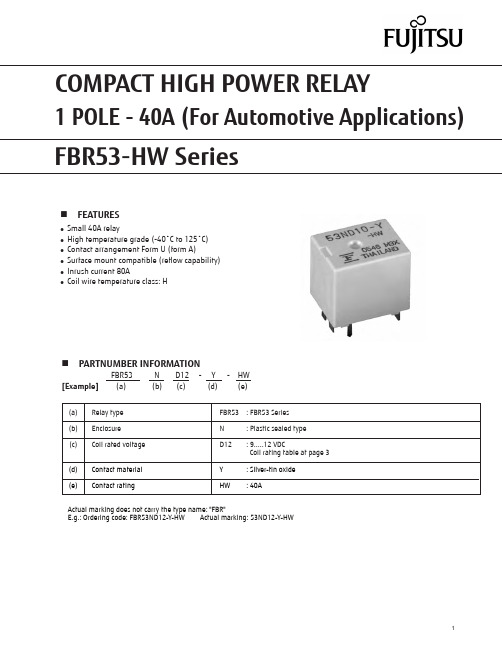
FTR-K1 SERIESn FEATURESlSmall 40A relay l High temperature grade (-40˚C to 125˚C)l Contact arrangement Form U (form A)l Surface mount compatible (reflow capability)l Inrush current 80A l Coil wire temperature class: HActual marking does not carry the type name: "FBR"E .g.: Ordering code: FBR53ND12-Y-HW Actual marking: 53ND12-Y-HW1 POLE - 40A (For Automotive Applications)n PARTNUMBER INFORMATIONFBR53 N D12 - Y - HW [Example] (a) (b) (c) (d) (e)(a) Relay type FBR53 : FBR53 Series (b) Enclosure N : Plastic sealed type (c) Coil rated voltage D12 : 9.....12 VDCCoil rating table at page 3 (d) Contact material Y : Silver-tin oxide (e)Contact ratingHW: 40A* Minimum switching loads mentioned above are reference values. Please perform the confirmation test with actual load before production since reference values may vary according to switching frequencies, environmental conditions and expected reliability levels.n SPECIFICATIONn COIL RATINGCoilCodeRated Coil Voltage (VDC)Coil Resistance +/- 10%(Ohm)Must Operate Voltage(VDC) *Must Release Voltage(VDC) *D09994 5.40.77.7 (at 125 °C)1.0 (at 125 °C)D1010117 6.30.89 (at 125 °C)1.2 (at 125 °C)D12121677.3 1.010.4 (at 125 °C)1.5 (at 125 °C)n CHARACTERISTIC DATANote: All values in the table are valid for 20°C and zero contact current, unless otherwise indicated.* Specified operate values are valid for pulse wave voltage.n DIMENSIONSUnit: mml Dimensionsl Schematics(BOTTOM VIEW) l PC board mountinghole layout (BOTTOM VIEW)l Tube carrier(pokayoke)1. General InformationlAll automotive relays produced by Fujitsu Components are compliant with RoHS directive 2002/95EC includingamendments.l Cadmium as used in electrical contacts is exempted from the RoHS directives on October 21st, 2005. (Amendment to Directive 2002/95/EC)l All of our automotive relays are lead-free.l Lead free solder plating on relay terminals is Sn-3.0Ag-0.5Cu, unless otherwise specified. This material has been verified to be compatible with PbSn assembly process.2. Recommended Lead Free Solder ProfilelRecommended solder Sn-3.0Ag-0.5Cu.RoHS Compliance and Lead Free Information3. Moisture SensitivitylMoisture Sensitivity Level standard is not applicable to electromechanical relays, unless otherwise indicated.4. Tin WhiskerslDipped SnAgCu solder is known as presenting a low risk to tin whisker development. No considerable length whisker was found by our in house test.We highly recommend that you confirm your actual solder conditionsFlow Solder condition:Pre-heating: maximum 120˚CSoldering: dip within 5 sec. at260˚C solder bathSolder by Soldering Iron:Soldering Iron Temperature: maximum 360˚C Duration:maximum 3 sec.Fujitsu Components International Headquarter OfficesJapanFujitsu Component LimitedGotanda-Chuo Building3-5, Higashigotanda 2-chome, Shinagawa-ku Tokyo 141, JapanTel: (81-3) 5449-7010Fax: (81-3) 5449-2626Email:**************Web: North and South AmericaFujitsu Components America, Inc.250 E. Caribbean DriveSunnyvale, CA 94089 U.S.A.Tel: (1-408) 745-4900Fax: (1-408) 745-4970Email:*********************.comWeb: /components EuropeFujitsu Components Europe B.V.Diamantlaan 252132 WV HoofddorpNetherlandsTel: (31-23) 5560910Fax: (31-23) 5560950Email:*****************.comWeb: /components/Asia PacificFujitsu Components Asia Ltd.102E Pasir Panjang Road#01-01 Citilink Warehouse ComplexSingapore 118529Tel: (65) 6375-8560Fax: (65) 6273-3021Email:*****************.comWeb: /sg/services/micro/components/©2013 Fujitsu Components Europe B.V. All rights reserved. All trademarks or registered trademarks are the property of their respective owners. The contents, data and information in this datasheet are provided by Fujitsu Component Ltd. as a service only to its user and only for general information purposes.The use of the contents, data and information provided in this datasheet is at the users’ own risk.Fujitsu has assembled this datasheet with care and will endeavor to keep the contents, data and information correct, accurate, comprehensive, complete and up to date.Fujitsu Components Europe B.V. and affiliated companies do however not accept any responsibility or liability on their behalf, nor on behalf of its employees, for any loss or damage, direct, indirect or consequential, with respect to this datasheet, its contents, data, and information and related graphics and the correctness, reliability, accuracy, comprehensiveness, usefulness, availability and completeness thereof.Nor do Fujitsu Components Europe B.V. and affiliated companies accept on their behalf, nor on behalf of its employees, any responsibility or liability for any representation or warrant of any kind, express or implied, including warranties of any kind for merchantability or fitness for particular use, with respect to these datasheets, its contents, data, information and related graphics and the correctness, reliability, accuracy, comprehensiveness, usefulness, availability and completeness thereof. Rev. July 26, 2013。
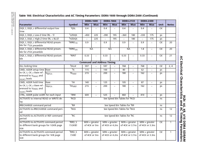
MEMORY存储芯片MT29F4G08ABADAH4-ITX D中文规格书
tWR1ck tWR2ck tWR_CRC_DM1c
k
MIN = tWR1ck + greater of (4CK
or 3.75ns)
MIN = 15ns MIN = 1CK + tWR1ck MIN = tWR1ck + greater of (5CK or 3.75ns)
tWR_CRC_DM2c
Delay from start of internal WRITE trans- tWTR_L_CRC_D
action to internal READ command – Same bank group when CRC and DM are both
M1ck
enabled
MIN = tWTR_L1ck + greater of (4CK
Parameter
Delay from start of internal WRITE transaction to internal READ command – Different bank group
Symbol tWTR_S1ck
tWTR_S2ck
DDR4-1600 Min Speed Bin Tables for tRP See Speed Bin Tables for tRAS
ns
ns
12
tRC
See Speed Bin Tables for tRC
ns
12
tRRD_S
MIN = greater MIN = greater MIN = greater MIN = greater CK
1, 5, 9 1, 5, 10 1, 6, 9 1, 6, 10 1, 5, 9 1, 5, 10 1, 6, 9
ATEQ-F520中文说明书

1. ATEQ F510 外观所以仪器能轻易而合身地装入壳内﹐随机附有电源供应器。
3. 仪器安装J1J324V0V 200 m AT3.3. 接头说明电子接头ATEQ F510 和F520 可应用下列方式﹐使用24V DC 电压来操作﹕✍使用本仪器所提供的24V DC 变压器﹔✍或当本仪器是从属端时透过网络线连接。
J1 接头(温度感应器/输出码/模拟输出)J2 接头电话插座﹐未使用J3从J3 输入接头激活程序欲从J3 输入接头激活程序﹐您必须选择接脚5 到9(一或多个)。
二位总加n+1。
J3 接头(I/O 输入/输出) 可程序化输入输入7可在环境/程序输入选单处予以参数化。
不同的可能性有﹕✍自动归零要求✍校准学习要求✍ATR 学习要求✍数量校准要求某些可能性只有在使用功能时才会出现。
J3 接头 (I/O 输入/输出)图标1 2 3 4 5 6 7 8 9 10 11 12 13 14 15 16J4 接头用来连接电源电压必须是24 V DC﹐最小电流为1.25 A本仪器可以由J3 接头继电器板的24 V DC 接脚供应J5 接头(遥控)14 3接脚1 网络接脚2 + 24V 电源接脚3 网络接脚4 0V 接地J6 输入接头(RS485)2 1保留给ATEQ 网络使用用来连接其它ATEQ 仪器(Lumberg 公接头)3 4接脚1 网络接脚2 + 24V 电源接脚3 网络接脚4 0V 接地J7 输出接头(RS485)1 2保留给ATEQ 网络使用用来连接其它ATEQ 仪器(Lumberg 母接头)4接脚1 网络接脚2 + 24V 电源接脚3 网络接脚4 0V 接地J8 接点(RS232)空气压力接头(以下简称为空压接头)空压接头可位于F520 仪器的前面或后面﹔如果是F510﹐则接头只能位于底部。
自动接头A用来连接自动气动接头自动接头B用来连接第二个自动气动接头空压输入/输出这些输出接头是用来连接零件的(测试件﹐标准件)。
瑞丰电子产品说明书

Features特征PLCC-2 Package. 垂直型表贴封装 Extremely wide viewing angle. 发光角度大Suitable for all SMT assembly and solder process. 适用于所有的SMT 组装和焊接工艺 Available on tape and reel. 适用于载带及卷轴 Moisture sensitivity level: 3. 防潮等级:3 Package:3000pcs/reel. 包装:3000颗/卷 RoHS compliant. RoHS 认证Description 描述The White LED which was fabricated using a blue chip and phosphors. 白光LED 由芯片激发荧光粉后,混光形成。
Applications 应用Optical indicator. 光学指示 Indoor display. 室内显示Landscape lighting,lamp belt. 景观照明,灯带等General use. 其他适合的应用Package Dimension 封装尺寸外形尺寸:3.0*2.0*1.27mmNOTES:备注1.All dimensions units are mm. (所有尺寸标注单位为毫米)2.All dimensions tolerances are ±0.2mm unless otherwise noted. (除特别标注外,所有尺寸允许公差为±0.2毫米)Electrical / Optical Characteristics at Ts=25°C 电性与光学特性Absolute Maximum Ratings at Ts=25°C最大极限参数值±10%.The Chromaticity Diagram色度图YTypical Optical Characteristics Curves典型光学特性曲线Fig.1-Forward Voltage Vs. Forward Current Fig.2-Forward Current Vs. Relative IntensityPackaging Specifications 包装规格⏹Carrier Tape Dimensions 载带尺寸Note:备注The t olerances unless mentioned ±0.1mm. Unit : mm 注:未注公差为±0.1毫米,尺寸单位:毫米。
6448H;中文规格书,Datasheet资料

ebm-papst St.Georgen GmbH&Co.KGHermann-Papst-Straße1D-78112St.GeorgenPhone+49772481-0Fax+49772481-1309info2@Nominal dataType6448HNominal voltage VDC48Nominal voltage range VDC28..60Speed min-14000Power input W26.0Min.ambient temperature°C-20Max.ambient temperature°C55Air flow m3/h480Sound power level B7.1Sound pressure level dB(A)63ml=max.load·me=max.efficiency·fa=running at free air·cs=customer specs·cu=customer unitSubject to alterationsTechnical featuresGeneral description Particular design features:Optional Vario-Pro:Highly flexible software configuration for the fan ensures an easily customisablesolution to meet the individual requirements of your application.General features:Housing made of aluminium,impeller made of fibreglass-reinforced PA;housing with grounding lugfor M4x8screw(Torx).48V version incl.screws.Electronic commutation completely integrated.Protected against reverse polarity and locking.Electrical connection to flat plugs,3x0.5mm.Air exhaust over bars.Direction of rotation counter-clockwise seen on rotor.Mass:760g.Mass0.760kgDimensions172x150x51mmMaterial of impeller Fiberglass-reinforced PA plasticHousing material Aluminum.Housing with grounding lug for screw M4x8(TORX).Direction of air flow Air exhaust over barsDirection of rotation Left,looking at rotorBearing Ball bearingsLifetime L10at40°C70000h50000hLifetime L10at maximumtemperatureConnection line Flat plugs3.0x0.5mm.Motor protection Protected against reverse polarity and locking.Locked-rotor protection Electronic blocking protection,with electronic motor current limit in the startup phase and when therotor is blocked.Approval VDE,CSA,UL,CEProduct drawing LuCharts:Air flow分销商库存信息: EBM-PAPST6448H。
FAIRCHILD FDMA8884 说明书

April 2012FDMA8884 N-Channel Power Trench®MOSFET FDMA8884Single N-Channel Power Trench®MOSFET30 V, 6.5 A, 23 mΩFeaturesMax r DS(on) = 23 mΩ at V GS = 10 V, I D = 6.5 AMax r DS(on) = 30 mΩ at V GS = 4.5 V, I D = 6.0 AHigh performance trench technology for extremely low r DS(on)Fast switching speedRoHS CompliantGeneral DescriptionThis N-Channel MOSFET is produced using FairchildSemiconductor‘s advanced Power Trench® process that hasbeen optimized for r DS(on) switching performance.ApplicationPrimary SwitchDD SGDDPin 1Drain SourceMicroFET 2X2 (Bottom View)Bottom Drain ContactDDDDSGMOSFET Maximum Ratings TA= 25 °C unless otherwise notedThermal CharacteristicsPackage Marking and Ordering InformationSymbol Parameter Ratings UnitsV DS Drain to Source Voltage30VV GS Gate to Source Voltage (Note 3)±20VI DDrain Current -Continuous (Package limited) T C = 25 °C8.0A6.5-Continuous T A = 25 °C (Note 1a)-Pulsed25P DPower Dissipation (Note 1a) 1.9W Power Dissipation (Note 1b)0.7T J, T STG Operating and Storage Junction Temperature Range-55 to +150°CRθJA Thermal Resistance, Junction to Ambient (Note 1a)65°C/WRθJA Thermal Resistance, Junction to Ambient (Note 1b)180Device Marking Device Package Reel Size Tape Width Quantity 884FDMA8884MicroFET 2x27 ’’12 mm3000 unitsFDMA8884 N-Channel Power Trench ® MOSFETElectrical Characteristics T J = 25 °C unless otherwise notedOff CharacteristicsOn CharacteristicsDynamic CharacteristicsSwitching CharacteristicsDrain-Source Diode CharacteristicsSymbolParameterTest ConditionsMinTypMaxUnitsBV DSS Drain to Source Breakdown Voltage I D = 250 μA, V GS = 0 V30 V ΔBV DSS ΔT J Breakdown Voltage Temperature CoefficientI D = 250 μA, referenced to 25 °C15mV/°C I DSS Zero Gate Voltage Drain CurrentV DS = 24 V, V GS = 0 V1μA I GSSGate to Source Leakage Current, Forward V GS = 20 V, V DS = 0 V100nAV GS(th)Gate to Source Threshold Voltage V GS = V DS , I D = 250 μA 1.2 1.8 3.0V ΔV GS(th) ΔT J Gate to Source Threshold Voltage Temperature CoefficientI D = 250 μA, referenced to 25 °C -5mV/°Cr DS(on)Static Drain to Source On Resistance V GS = 10 V, I D = 6.5 A1923m ΩV GS = 4.5 V, I D = 6.0 A2530V GS = 10 V, I D = 6.5 A, T J = 125 °C 2530g FSForward TransconductanceV DD = 5 V, I D = 6.5 A26S C iss Input Capacitance V DS = 15 V, V GS = 0 V,f = 1 MHz339450pF C oss Output Capacitance132175pF C rss Reverse Transfer Capacitance1828pF R gGate Resistance1.1Ωt d(on)Turn-On Delay Time V DD = 15 V, I D = 6.5 A,V GS = 10 V, R GEN = 6 Ω510ns t r Rise Time110ns t d(off)Turn-Off Delay Time 1120ns t f Fall Time110ns Q g(TOT)Total Gate Charge V GS = 0 V to 10 VV DD = 15 VI D = 6.5 A5.47.5nC Total Gate Charge V GS = 0 V to 4.5 V 2.7 3.7nC Q gs Total Gate Charge1.0nC Q gdGate to Drain “Miller” Charge0.9nCV SD Source to Drain Diode Forward Voltage V GS = 0 V, I S = 6.5 A (Note 2) 0.86 1.2V t rr Reverse Recovery Time I F = 6.5 A, di/dt = 100 A/μs1628ns Q rrReverse Recovery Charge410nCNOTES:1. R θJA is the sum of the junction-to-case and case-to-ambient thermal resistance where the case thermal reference is defined as the solder mounting surface of the drain pins. R θJC is guaranteed by design while R θCA is determined by the user's board design.2. Pulse Test: Pulse Width < 300 μs, Duty cycle < 2.0 %.3. As an N-ch device, the negative Vgs rating is for low duty cycle pulse occurrence only. No continuous rating is implied.a. 65 °C/W when mountedon a 1 in 2 pad of 2 oz copper.b. 180 °C/W when mounted on a minimum pad of 2 oz copper.®MOSFETMOSFETMOSFETFDMA8884 N-Channel Power Trench ® MOSFET*Trademarks of System General Corporation, used under license by Fairchild Semiconductor.DISCLAIMERFAIRCHILD SEMICONDUCTOR RESERVES THE RIGHT TO MAKE CHANGES WITHOUT FURTHER NOTICE TO ANY PRODUCTS HEREIN TO IMPROVE RELIABILITY, FUNCTION, OR DESIGN. FAIRCHILD DOES NOT ASSUME ANY LIABILITY ARISING OUT OF THE APPLICATION OR USE OF ANY PRODUCT OR CIRCUIT DESCRIBED HEREIN; NEITHER DOES IT CONVEY ANY LICENSE UNDER ITS PATENT RIGHTS, NOR THE RIGHTS OF OTHERS. THESE SPECIFICATIONS DO NOT EXPAND THE TERMS OF FAIRCHILD’S WORLDWIDE TERMS AND CONDITIONS, SPECIFICALLY THE WARRANTY THEREIN, WHICH COVERS THESE PRODUCTS.LIFE SUPPORT POLICYFAIRCHILD’S PRODUCTS ARE NOT AUTHORIZED FOR USE AS CRITICAL COMPONENTS IN LIFE SUPPORT DEVICES OR SYSTEMS WITHOUT THE EXPRESS WRITTEN APPROVAL OF FAIRCHILD SEMICONDUCTOR CORPORATION.As used here in:Life support devices or systems are devices or systems which, (a) areintended for surgical implant into the body or (b) support or sustain life, and (c) whose failure to perform when properly used in accordance with instructions for use provided in the labeling, can be reasonably expected to result in a significant injury of the user.2.A critical component in any component of a life support, device, or system whose failure to perform can be reasonably expected to cause the failure of the life support device or system, or to affect its safety or effectiveness.PRODUCT STATUS DEFINITIONS Definition of Terms2Cool™AccuPower™AX-CAP™*BitSiC ®Build it Now™CorePLUS™CorePOWER™CROSSVOLT ™CTL™Current Transfer Logic™DEUXPEED ®Dual Cool™EcoSPARK ®EfficentMax™ESBC™Fairchild®Fairchild Semiconductor®FACT Quiet Series™FACT®FAST ®FastvCore™FETBench™FlashWriter ® *FPS™F-PFS™FRFET®Global Power Resource SM Green Bridge™Green FPS™Green FPS™ e-Series™G max ™GTO™IntelliMAX™ISOPLANAR™Marking Small Speakers Sound Louder and Better™MegaBuck™MICROCOUPLER™MicroFET™MicroPak™MicroPak2™MillerDrive™MotionMax™Motion-SPM™mWSaver™OptoHiT™OPTOLOGIC ®OPTOPLANAR ®PowerTrench ®PowerXS™Programmable Active Droop™QFET ®QS™Quiet Series™RapidConfigure™Saving our world, 1mW/W/kW at a time™SignalWise™SmartMax™SMART START™Solutions for Your Success™SPM ®STEALTH™SuperFET ®SuperSOT™-3SuperSOT™-6SuperSOT™-8SupreMOS ®SyncFET™Sync-Lock™®*The Power Franchise ®®TinyBoost™TinyBuck™TinyCalc™TinyLogic ®TINYOPTO™TinyPower™TinyPWM™TinyWire™TranSiC ®TriFault Detect™TRUECURRENT ®*μSerDes™UHC ®Ultra FRFET™UniFET™VCX™VisualMax™VoltagePlus™XS™®™Datasheet Identification Product Status DefinitionANTI-COUNTERFEITING POLICYFairchild Semiconductor Corporation’s Anti-Counterfeiting Policy. Fairchild’s Anti-Counterfeiting Policy is also stated on our external website, , under Sales Support .Counterfeiting of semiconductor parts is a growing problem in the industry. All manufactures of semiconductor products are experiencing counterfeiting of their parts. Customers who inadvertently purchase counterfeit parts experience many problems such as loss of brand reputation, substandard performance, failed application, and increased cost of production and manufacturing delays. Fairchild is taking strong measures to protect ourselves and our customers from the proliferation of counterfeit parts. Fairchild strongly encourages customers to purchase Fairchild parts either directly from Fairchild or from Authorized Fairchild Distributors who are listed by country on our web page cited above. Products customers buy either from Fairchild directly or from Authorized Fairchild Distributors are genuine parts, have full traceability, meet Fairchild’s quality standards for handing and storage and provide access to Fairchild’s full range of up-to-date technical and product information. Fairchild and our Authorized Distributors will stand behind all warranties and will appropriately address and warranty issues that may arise. Fairchild will not provide any warranty coverage or other assistance for parts bought from Unauthorized Sources. Fairchild is committed to combat this global problem and encourage our customers to do their part in stopping this practice by buying direct or from authorized distributors.®。
FAFAFAFA规格书

Unit Max. –3.2 µA
V V
Output ON/OFF control circuit section (CS pin)
Item Source current (CS pin) ON/OFF control threshold voltage (CS pin)
Hysteresis voltage
Type
FA5510P FA5510N FA5511P FA5511N FA5514P FA5514N FA5515P FA5515N
Max. duty cycle (typ.) 46%
70%
46%
70%
Polarity of overcurrent Package detection
+
DIP-8
SOP-8
Symbol VCC1 VCC2 IOUT VFB VIS IREF ICS Pd
Ta Tj Tstg
Rating 30 Self limiting ±1.5 –0.3 to 5.0 –0.3 to 5.0 –10 +2.0 800 (DIP-8) 400 (SOP-8) –30 to +85 125 –40 to +150
SQ FF
GND (4)
5V Controlled block
RT(1)
IS-(3)
■ Dimensions, mm
SOP-8
8
5
3.9 6.0±0.2
1.8max
+0.1
0.20 –0.05
1
4
4.9
0.4±0.1 1.27
DIP-8
8
5
0~8°
ATEN 520M 4x4 6x4+2 8x8 16x16 HDMI 矩阵开关说明书
This symbol, a lightning flash with arrowhead, drawn withinan equilateral triangle, is intended to alert the user to thepresence of uninsulated dangerous voltage within theproduct’s enclosure that may be of sufficient magnitude toconstitute a risk of electric shock to persons.The exclamation point within an equilateral triangle isintended to alert the user to the presence of importantoperating and maintenance (servicing) instructions in the literature accompanying the appliance.To reduce the risk of fire or electric shock, read and follow all instructions and warnings in this manual. Keep this manual for future reference.1. Do not expose this apparatus to rain or moisture. Do not expose this equipment to dripping or splashing, andensure that no objects filled with liquids, such as vases, are placed on the equipment. Do not use this apparatus near water.2. Do not remove cover. No user serviceable parts inside.3. Clean only with a dry cloth.4. Do not block any ventilation openings. Install according to manufacturer’s instructions.5. Do not install near any heat sources such as radiators, heat registers, stoves or other apparatus (includingamplifiers) that produce heat.6. Do not override the safety purpose of the polarized or grounding plug. A polarized plug has two blades, oneof which is wider than the other. A grounding plug has two matching blades and a third grounding prong. The wide blade or the third prong is provided for your safety. If the provided plug does not fit into your outlet,consult an electrician for replacement of the obsolete outlet.7. Protect the power cord from being walked on or pinched, particularly at the plug end and where the powercord is attached to the apparatus.8. Only use attachments and accessories specified by the manufacturer.9. Refer all servicing to qualified service personnel. The apparatus requires service when it is damaged in any way(for example: when the power supply cord or plug is damaged, when liquids have been spilled onto or objects have fallen into the apparatus, the apparatus has been exposed to rain or moisture, does not operate normally, or has been dropped.)10. To completely disconnect this equipment from power, disconnect the power supply cord from the poweroutlet.1. Overview (4)2. Models (4)3. Package Contents (4)4. Downloading the utility (5)5. Utility File Location (5)5.1. B-520-MTRX-230-16x16 Files (5)6. Communicating with the B-520-MTRX-230 (5)6.1. Serial Connection (5)7. Installation & Setup (6)7.1. Basic Installation Diagram (6)7.2. COM Port Settings (6)7.3. Initializing Communication (6)7.4. Stopping Communication (6)8. EDID Configuration (7)8.1. Display EDID for Particular Input/Output (7)8.2. Display EDID for All Inputs / Outputs (8)8.3. Save Configuration for Inputs / Outputs (8)8.4. Learn EDID to Input (9)8.5. Auto EDID Learn (10)9. Advanced Setup Using the Configuration Utility (10)9.1 Output Control (10)10. Firmware Update (11)11. Network Configuration (11)12. Resetting Factory Defaults (12)13. Other Settings (12)13.1. IR Source Routing (12)13.2. Front Panel IR Enable (12)13.3. System IR Enable (12)13.4. Matrix Control from Room Enable (13)13.5. Front Panel Power Button Active (13)14. Input / Output Operation (13)14.1. Connection Status (13)14.2. Input/Output Control (14)15. Appendix: Configuration Utility Home Screens (14)15.1. B-520-MTRX-230-4x4 (14)15.2. B-520-MTRX-230-8x8/6x4+2 (15)15.3. B-520-MTRX-230-16x16 (15)16. Contacting Tech Support (16)17. Warranty (16)This manual outlines the operation and use of the B-520-MTRX-230 PC-based Configuration Utility software. Please read through the entire document before attempting to configure a B-520-MTRX-230. Should you have any questions after reading this document, please contact SnapAV Technical Support.The following models are covered in this manual. The functionality of the Configuration Utility is very similar for all models. Any significant differences are covered by model.• B-520-MTRX-230-4x4• B-520-MTRX-230-6x4+2• B-520-MTRX-230-8x8• B-520-MTRX-230-16x16Before you begin, make sure the following items are available and ready for use:• B-520-MTRX-230• B-520-MTRX-230 Installation Manual• PC running Windows XP or newer Windows OS• Serial Cable to connect the B-520-MTRX-230 to the PC• DB9 to USB adapter (if the PC does not have a serial port built-in)• List of the sources (Inputs) and displays (Outputs) used in the system (consult system chart in the B-520-MTRX-230 manual)• Knowledge of this document and the devices being used in the systemThe software utility is included on the CD provided with the B-520-MTRX-230 and can also be downloaded from the product page at . Check the site for periodic updates to ensure that the latest version of the utility is being used.The B-520-MTRX-230 software utility is a standalone program that does not require installation. Afterdownloading the utility, unzip the downloaded file to a location that is easy to remember and locate when needed, like the example below:• C:\My Documents\Binary\B-520-MTRX-230\ConfigurationUtility5.1. B-520-MTRX-230-16x16 FilesThere are 2 additional “.DLL” type files included with the utility “EXE” that must be placed in the same folder as the utility.6.1. Serial ConnectionThe B-520-MTRX-230 and PC communicate over DB9 straight-through serial cable. Before connecting, verify that the pin configuration of the cable matches the diagram below.Should the PC not have a built in DB9 connection, a USB to RS-232 adapter may be used, however it is strongly recommended that firmware updates are not performed using an adapter.Matrix DB9PC Serial DB9B-520-MTRX-230Pin 2 TxD (Data Transmit) Pin 3 RxD (Data Receive) Pin 5 GNDComputerPin 2 RxD (Data Receive)Pin 3 TxD (Data Transmit)Pin 5 GNDToToToFIGURE 17.1. Basic Installation DiagramComplete the basic installation section to set up the matrix switcher for media distribution before completing any other setup. Use this diagram for reference during basic installation of the matrix switcher, sources, displays and wiring.7.2. COM Port SettingsThe COM port on the PC should be set to 9600 Baud, 1 Stop Bit, No Parity.Select the COM port on the computer that is connected to the B-520-MTRX-230 from the list of available COM ports.If the connected COM port does not appear in the list, refer to the PC’s “Device Manager” to verify that COM ports have been installed and have the right communication settings. Find the Device Manager by searching from the Start menu search bar, or go to Control Panel > Devices and Printers > right-mouse-click and select “Device Manager.”7.3. Initializing CommunicationSelect the “Connect” button to initiate communication between the B-520-MTRX-230 and the computer.Once connected:• Button name will change to “Disconnect”• Status box will change to “Connected” and turn green.If this does not occur after a few moments, perform these steps:1. Verify that the correct COM port is selected;2. Verify communication settings on the PCs COM port;3. Verify that the cable has the correct PIN configuration and that it is functioning correctly.If communication cannot be established after performing these steps, please contact SnapAV tech support.7.4. Stopping CommunicationClick the “Disconnect” button to stop communication between the B-520-MTRX-230 and the computer.The purpose of EDID Configuration is to set the EDID for each input appropriately. This EDID will be passed to the connected source input. Unless the source has a fixed audio or video format, it will transmit content at the best audio and video formats that do not exceed the capabilities specified in the EDID. Note that all outputs on the B-520-MTRX-230 receive the same audio and video format.For example, assume you have two displays (Outputs) that will view the source connected to Input 1. One of the displays is capable of 7.1 multi-channel audio but the other is only capable of stereo audio. In this case, you will store an EDID in Input 1 that restricts the audio to stereo so that both display outputs will produce audio.Select “Configure EDID’s” to access EDID configurations.NOTE: If the PC is not communicating with the B-520-MTRX-230, a “NOT CONNECTED” window will appear.FIGURE 28.1. Display EDID for Particular Input/OutputRead EDID allows you to read the currently stored EDID for each Input and to read the EDID from display (if any) connected to each HDMI and HDBaseT output. Note that EDIDs for the Inputs are displayed in the upper left box while EDIDs for the outputs are displayed in the lower left box.1. Select an input or an output from the dropdown list:2. Select READ to display the information.3. The EDID values for the selected Input or Output will be displayed on the left side of the screen.8.2. Display EDID for All Inputs / Outputs1. READ ALL will read and display the currently assigned EDID for each Input and the EDID from each connecteddisplay.2. The EDID values for all Inputs and Outputs will be displayed on the left side of the screen.8.3. Save Configuration for Inputs / OutputsThis function allows you to save an EDID to disk for future use. A common use of this function is storing the EDIDs for commonly used TVs on disk. These can be recalled from disk (see EDID Learning below) and stored in the EDID Input locations even if the display is not currently connected.1. Select an input or an output from the dropdown list:1. Click “READ” to display the information.2. Click “SAVE” to save the file.3. Browse to the location of your choice to save the configuration file.Suggested Folder Location:C:\My Documents\Binary\B-520-MTRX-230\EDIDConfigurationsFIGURE 34. Create a name for the file that clearly describes the contents.8.4. Learn EDID to InputThe following examples are for the B-520-MTRX-230-8x8, but apply to all models.EDIDs are learned into the B-520-MTRX-230 via the HDMI and HDBaseT output connections.If you are learning from a connected display, the steps below can be followed to learn EDIDs from a display into the B-520-MTRX-230:1. Select the location of the device whose EDID you will learn from in the EDID Learning “From” dropdown list:Available ChoicesNOTE: When “From File” is selected, a window will open when you learn (Step 3 on next page) that allows you to navigate to the location where an EDID configuration file was saved. Select the desired file and select “Open”.1. Select an Input to learn to in the “EDID Learning TO” dropdown list:Available Choices2. Select the LEARN buttonThe selected EDID is stored in the selected Input locations.8.5. Auto EDID LearnThe B-520-MTRX-230 includes an automatic function that will determine the EDID with the best quality video that will work with all connected displays.If all sources (Inputs) are to be viewable on all Displays (HDMI and HDBaseT Outputs), this function provides an easy mechanism for determining the EDIDs to store in all Inputs.If some sources (such as a Blu-Ray player) are only viewed on some displays (Outputs), this method may provide a more restrictive EDID than desired for some displays (Outputs).To see the results of Auto Learn, Read EDID from Input 1. This EDID is stored in all Input EDID locations.NOTE: Auto EDID sets audio to 2ch for all inputs regardless of the capability of the connected displays. If multi-channel audio is desired, embedded EDIDs or Learned EDIDs will need to be used.9.1 Output ControlSelecting “View Outputs” opens a window that allows outputs to be turned on or off. This can be used fortroubleshooting the B-520-MTRX-230 and connections.FIGURE 4The process to update firmware varies slightly between the 4 models; however the types of files loaded are the same as listed below:1. Main- Firmware for the main processor in the matrix.2. DB Board- Firmware for processors that manage Inputs and Outputs.3. HDBaseT- Firmware for the HDBaseT Output Processors.Instructions for updating Firmware on a matrix are detailed on the Firmware Update Page for that product. Before beginning the Firmware Update process download and unzip the latest firmware update from theB-520-MTRX-230 product page for the matrix to be updated and store in a location you will remember on your PC. Be sure the firmware file from the downloaded folder is not compressed or in a compressed folder before updating. IMPORTANT: A hardware RS-232 serial port on a laptop or desktop PC may be more reliable for updating firmware than a USB to RS-232 Adapter. If you have trouble updating using an adapter, please use a PC with a built-in RS-232 port.Displays and sets the Network IP address for all B-520-MTRX-230-Matrix switchers.NOTE: Only Static IP address mode is available – DHCP is not supported.NOTE: The default IP Address for the matrix is 192.168.0.99. The IP Address and Subnet Mask are not reset during FIRMWARE UPDATE or RESET FACTORY DEFAULTS operations.When NETWORK CONFIGURATION is selected, the following window is shown. If you want to know what the current IP address and Subnet Mask are. press the READ FROM DEVICE button. If you have not reset, the IP Address in the matrix iwill be 192.168.0.99 as shown below.To change the values, enter the desired IP Address and Subnet Mask, and then press WRITE TO DEVICE. After changing the values, confirm the update worked correctly by clicking READ FROM DEVICE again.After changing the network configuration, the matrix should be turned off and on again in order to use the new settings.FIGURE 5Select to restore factory default settings for Inputs/Outputs Factory Values:EDIDs for all Inputs: 1080P60, 2 Channel AudioI/O: All Outputs set to Input 1During the installation of a matrix, there are settings that provide Advanced Configuration not available via the remote control. These allow for fine tuning the matrix when used under certain conditions and the settings listed below are not available from the remote.FIGURE 613.1. IR Source Routing:The 3.5mm IR Output to Source jacks on the back of the matrix may be used in two ways. In the default setting, IR coming from the room is routed to the IR Output corresponding to the selected Source (Input). Set IR Source Routing to Yes for this functionality (default). If set to No, the IR coming from a room is routed to the IR output corresponding to the Room (Output) number.13.2. Front Panel IR EnableUse this setting to Enable (default) and Disable the front panel IR receiver. This is useful if the matrix is placed in a location that causes IR flooding from sunlight or other source. This setting only affects the Front Panel IR Receivers.13.3. System IR EnableUse this setting to disable the System IR Input on the back of the matrix.13.4. Matrix Control from Room EnableWhen Set to Yes (default), IR coming from a Room can be used to control the matrix. When set to No, matrixcommands sent from a room will not control the matrix. This setting may be needed if IR flooding from sunlight or other source is sometimes present in one or more rooms.13.5. Front Panel Power Button ActiveUse this feature to Disable/Enable the front panel power button of the matrix when using an Automation System.This will prevent the matrix from being powered OFF which may disrupt matrix control from an automationsystem.The operating status is displayed and control of inputs and outputs is performed with the grid on the left side of the screen. It is provided so that the functionality of the system can be tested and controlled.Here you can perform the following:• View which inputs have sources connected and turned on• View which outputs are un-muted• View which input is assigned to an output• Assign inputs to outputs14.1. Connection StatusFIGURE 7Note that a green box does not indicate if a display is connected or OFF. Should no image be visible on the display, verify that it is connected and ON.14.2. Input / Output Control1. Assign a single Input to an Output2. Select a gray box under the input and next to the output. The box selected will turn green.3. Assign any Input to all Outputs4. Select the Input number in the top row. All boxes under that input will turn green.The home screen for each version of the utility is provided in this section for reference. 15.1. B-520-MTRX-230-4x4FIGURE 815.2. B-520-MTRX-230-8x8/6x4+2FIGURE 9 15.3. B-520-MTRX-230-16x16FIGURE 10If you need further clarification, please call tech support at 866.838.5052, or email******************. For other information, instructional videos, support documentation, or ideas, visit our website and view your item’s product page at .Phone: (866) 838-5052Email:**********************2 Year Limited WarrantyThis Binary product has a 2-Year limited warranty. This warranty includes parts and labor repairs on allcomponents found to be defective in material or workmanship under normal conditions of use. This warranty shall not apply to products that have been abused, modified or disassembled. Products to be repaired under this warranty must be returned to SnapAV or a designated service center with prior notification and an assigned return authorization number (RA)..®Rev: 151117-0930。
瑞昱 SZK、ZLMK 系列手动张力控制器(板) 使用说明书

SZK、ZLMK系列手动张力控制器(板)使用说明书感谢使用本厂SZK、ZLMK系列手动张力控制器(板)在安装本控制设备之前,请阅读本说明书ZLMK分体式手动张力控制板是SZK系列手动张力控制器内的主控调节板,属于散件类产品,可以和其他散件类产品(如指针式电流表或数显式电流表等)配套使用,满足了客户对特殊机器的配置,ZLMK分体式手动张力控制板性能和SZK系列手动张力控制器相同。
两者都有数字式和指针式两种可供选择。
前者更具有直观形象的读数指示。
主电路采用电源经变压器输出,整流滤波后,以调节脉宽占空比的方式调节电流的反馈型脉宽PWM控制输出,解决了以往大功率晶体管压降高、发热严重的问题,而且电路具有电流输出稳定,功率管发热低等特点,同时也使整机的结构紧凑。
由于电路设计时采用了单电源30V输入故使张力板工作,接线更简单,并带过流和短路保护使系统更稳定可靠。
二、参数参数SZK系列控制器参数:1、输入电压:AC220V±15%50/60HZ2、输出电流:DC0-2A/3A(适配负载阻抗8-12Ω)3、输出电压:DC0-24V4、电流波动:≤0.02A5、输出辅助电压:DC5V、12V、100mA6、适配变压器:63W、220V/30V,100W、220V/30V7、适配磁粉离合器:0.5-20/40KG8、外型尺寸:260×145×115(mm)(长×宽×高)ZLMK-2A控制板参数:1、工作电压:AC30V±15%2、输出电流:DC0-2A3、输出电压:DC0-24V4、电流波动:≤0.02A5、输出辅助电压:DC5V、12V、100mA6、适配变压器:63W、220V/30V7、适配磁粉离合器:0.5-20KG8、外型尺寸:95×75×40(mm)(长×宽×高)ZLM K-3A控制板参数:1、工作电压:AC30V±15%2、输出电流:DC0-3A3、输出电压:DC0-24V4、电流波动:≤0.02A5、输出辅助电压:DC5V、12V、100mA6、适配变压器:100W、220V/30V7、适配磁粉离合器:0.5KG-40KG8、外型尺寸:130×85×40(mm)(长×宽×高)1、调节板接线方法OUT-OUT+5V IN 0V AC30V +5V GNDZLMK-2A/3A 张力控制板接线图2、控制器接线方法SZK-2A/3A 手动张力控制器接线图四、安装须知安装须知1、用户在使用本产品之前,应仔细阅读说明书。
Infiniium54850系列

Infiniium54850系列
佚名
【期刊名称】《电子测试》
【年(卷),期】2003(000)001
【总页数】1页(P126)
【正文语种】中文
【中图分类】TM935.3
【相关文献】
1.系列连续剧:连续剧和系列剧的过渡与融合——从系列连续剧的叙事艺术谈起 [J], 王帆;邓彦
2.艾里逊变速箱公司发布1000系列和2000系列最新节油技术进一步提高此系列产品的燃油经济性 [J],
3.王蒙的"季节"系列对《红楼梦》技法上的继承--"季节"系列与《红楼梦》系列论文之二 [J], 李永建
4.OSG:A丝锥硬质合金系列——A-CSF/A-CHT、硬质合金钻头——AD/ADO系列、低阻力抗振铣刀——AE-VMS系列 [J],
5.Y系列、Y2系列和Y3系列(IP55、机座号355~450)标准制修订会议召开 [J],因版权原因,仅展示原文概要,查看原文内容请购买。
驱动主板规格及承认书

目录一、概述二、主要特性三、A/D驱动板外观图四、VGA预设支持模式表五、输入/输出接口定义及接口电气要求六、主板结构与尺寸七、运输,存储,使用要求一、功能概述JRY1A31液晶显示器控制板卡(支持1440*900及以下分辨率TFT Panel,主芯片用TSUM1PFR-LF或TSUM1PLR-LF。
)它完成从PC输出的VGA模拟信号到液晶模块能够支持的LVDS 信号的转换,该设计主要用于配接TFT LCD PANEL,该产品适用于1440*900及以下分辨率8-BIT和6-BIT屏,实现模拟R、G、B输入和输出,实现最高分辨率可达UXGA的模拟R、G、B输入信号的再现,色彩再现可支持到24bit,最高可达16.7百万像素,ADC 频率达165MHz,并具有去抖动,降躁,锐度增强等特殊功能,使色彩再现更逼真、更鲜艳、更生动。
可实现同步自动检测。
同步方式要求使用行场分离的同步信号;具有精美的OSD界面风格,7种可供选择的OSD语言。
软件支持16:10与4:3显示模式的切换功能,此功能为玩游戏的用户提供了很大的方便,主板上的软件支持在线更新,本产品支持VGA功能,最大输出分辨率支持1440*900。
非另有说明,产品所符合规范在本文档内描述。
二、主要特性控制板支持规格:输入信号:模拟RGB(0.7Vp-p),行场分离同步信号支持模式:DOS,VGA,SVGA,XGA,SXGA,WXGA, 色彩:18bit/24bit (根据屏参数可选择)行同步范围:31.5-80KHz场同步范围:60-75Hz输出信号:LVDS 标准控制按键:POWER、LEFT、RIGHT、AUTO、MENU、UP、DOWN、7键(可根据客户要求,通过软件更改成5键或6键)OSD 菜单:亮度,对比度,自动校正,相位,时钟,行场位置,功能设置,复位等目前国际流行标准功能OSD 语言:English,Espanlo,Francais,Deutsch,中文,韩语等多国语言程序升级: 支持VGA在线升级电源输入:此板配内置二合一电源板,5.0 VDC(+/-0.2V)电源操作:正常工作模式,低功耗模式待机功耗:<1.0WPCB尺寸:62mm(L)×62mm(W)×1.2mm(H)即插即用:支持配接 TFT LCD PANEL类型可支持AU,SAMSUNG,CPT,SHARP,CHIMEI,HUAMMSTAR,TOSHIBA ,LG-Philips 等等厂家的19英寸及其以下的大多数型号的数字TFT LCD,具体可能需要对 LCD接口电缆和软件做一定修改。