气体管路技术规格书
气体灭火系统技术规格书

气体灭火系统技术规格书一、管道要求1、输送气体灭火剂的管道采用内外热镀锌无缝钢管,其质量符合现行国家标准《输送流体用无缝钢管》GB/T8163《高压锅炉用无缝钢管》GB5310等的规定。
2、输送气体灭火剂管道的连接,当公称直径小于或等于80mm时,采用螺纹连接,大于80mm时,采用法兰连接。
无缝钢管及钢制管道附件的内外壁应采用热镀锌法镀锌,应做镀锌层的重量测定。
其平均值应不小于500g/m²。
其中任何一个试样不得小于480g/m².无缝钢管应做镀锌层均匀性试验。
钢管试样在硫酸铜液体中连续浸渍5次不得变红(镀铜色)。
无缝钢管的内外表面应有完整的镀锌层。
不得有未镀锌上锌的黑斑和气泡存在。
允许有不大的粗糙面和局部锌瘤存在。
无缝钢管表面应进行钝化处理或其他保护层。
二、施工要求1、气体灭火系统安装分为气体灭火系统主设备和喷嘴管路系统,增加弯头和延长管路等须经设计同意。
2、公称直径大于或等于50mm的主干管道,垂直方向和水平方向至少应各安装一个防晃支架。
当穿过建筑物楼层时,每层应设一个防晃支架。
当水平管道改变方向时,应增设防晃支架,防晃支架见03S402室内管道支架及吊架支、吊架之间的最大间距3、管道穿过墙壁、楼板处设置套管。
穿墙套管的长度与墙体厚度一致,,穿过楼板的套管长度高出版面50mm。
管道与套管之间的缝隙采用柔性防火封堵材料填塞紧密。
穿墙、穿楼板钢套管尺寸4、管道安装完成后应进行水压(气压)强度试验,水压试验压力为系统减压后管网最大工作压力的1.5倍,(气压试验压力为系统减压后管网最大工作压力的1倍),持续5分钟无明显泄露,且不变形。
5、分布管系的水平定向敷设坡度取顺向0.001-0.003。
6、管道系统安装完成后,应进行气密性试验,试验介质为氮气或压缩空气,试验压力为减压后管网最大工作压力,在无气源补充的条件下,持续3分钟,压力下降不得超过试验压力的10%。
7、管网部分的管件采用锻件,工作压力为18MPa。
川气东输管道技术规格书

-和管件连接管子的外径,mm。
6.4制造商可采用更高的试验压力,但应考虑高压下的安全性和适应性。
6.5设计时应考虑上述条款提及的性能要求,以及取决于管件形状的系数。
6.6管件应按提供的管件工作参数及相连接的接管尺寸进行设计,清管三通内径应不小于连接管公称内径的97%,档条选材需经业主或项目设计单位认可。
10.1.6原材料进厂后,管件制造商应按质量证明书等进行验收,并对钢管原材料的外观、尺寸和理化性能进行抽检。业主统一采购的原材料,其理化性能统一验收。
10.1.7原材料表面应无油污,在制造、搬运、装卸过程中不允许与低熔点金属(Cu、Zn、Sn、Pb等)接触,否则应采取适当的措施(如喷砂)清除。
10.2材料化学成分
b. V+Nb+Ti≤0.15
10.2..2为了满足表11.1要求的抗拉性能,用高强度低合金钢制作的管件,其合金元素的选用应由业主和制造商协商确定,并由制造商按所供管件强度级别分别作出适用性评价报告。
10.2..3根据下式计算碳当量(C.E.)和(Pcm),对WFHY-485(X70),C.E.不应超过0.44%,Pcm不应超过0.22%;对WFHY-415(X60)C.E.,不应超过0.43%,Pcm不应超过0.21%;对其它材料的管件,C.E.不应超过0.40%。
10.1.2管件材料应为各类锻制钢坯、锻制钢棒、钢板、无缝钢管及直缝焊管。
10.1.3管件用钢应为可焊性良好的碳钢和高强度低合金钢。
10.1.4当焊接需要预热时,制造商应说明规定的预热条件,并在管件上做出永久性标记。
10.1.5原材料应有质量证明书,其检验项目应符合相关标准的规定或订货要求,无标记、无批号、无质量证明书或质量证明书项目不全的钢材不得使用。不允许使用低价劣质材料,材料的来源应经业主审批,未得到书面认可,不得使用。
工业气体输送管道规格

工业气体输送管道规格工业气体输送管道规格一、引言工业气体输送管道是工业生产中必不可少的设备之一,其作用是将气体从一个地方输送到另一个地方,以满足工业生产的需要。
在实际应用中,为了确保安全、高效和经济,需要对工业气体输送管道进行规格化建设。
本文将从管道材料、管道直径、管道壁厚、管道接口、管道支架、管道防腐、管道安全等方面详细介绍工业气体输送管道的规格。
二、管道材料工业气体输送管道的材料应根据输送气体的性质、压力、温度等因素来选择。
常用的管道材料有碳钢、不锈钢、铜、铝等。
其中,碳钢管道适用于一般气体输送,不锈钢管道适用于对氧化性、腐蚀性较强的气体输送,铜管道适用于高温高压气体输送,铝管道适用于轻质气体输送。
管道直径应根据气体流量、输送距离、输送压力等因素来确定。
一般来说,管道直径越大,气体输送的能力越强,但也会增加成本。
因此,应根据实际需要和经济性来选择合适的管道直径。
四、管道壁厚管道壁厚应根据输送气体的压力和温度来确定。
一般来说,气体压力和温度越高,管道壁厚就需要越厚。
同时,应考虑管道材料的强度和耐腐蚀性等因素。
五、管道接口管道接口应采用标准的法兰连接,以确保连接紧密、牢固、易于维修。
法兰连接应符合相关标准,如GB/T9119-2000。
六、管道支架管道支架应采用耐腐蚀、耐高温材料制作,以确保管道的牢固、稳定、安全。
管道支架应设置在距离管道末端不超过1米的距离处,且支架间距不超过2米。
工业气体输送管道应进行防腐处理,以提高管道的耐腐蚀性和寿命。
常见的防腐方式有涂层防腐、镀锌、喷涂等。
应根据输送气体的性质和环境条件来选择合适的防腐方式。
八、管道安全工业气体输送管道应采取安全措施,以确保管道的安全运行。
管道应设置安全阀、压力表、温度计等监测装置,以及防火、防爆、防静电等安全设施。
同时,应对管道进行定期检查、维护和保养,及时发现和排除安全隐患。
九、结论综上所述,工业气体输送管道的规格应根据输送气体的性质、压力、温度等因素来确定,管道材料、直径、壁厚、接口、支架、防腐、安全等方面应进行规格化建设,以确保管道的安全、高效、经济运行。
GP-01-GI00-PL-SP-002输气管道工程感应加热弯管母管技术规格书26
9.2.2 按照 API Spec 5L:2007 标准要求执行。 9.2.3 按照 API Spec 5L:2007 标准要求执行。 CEPcm,计算公式:
CE Pcm = C + Si Mn + Cu + Cr Ni Mo V + + + + + 5B 30 20 60 15 10 .......... .......... (1)
A 薄 ≤2.5 厚 ≤2.5 薄 ≤2.5
非金属夹杂物级别限定
B 厚 ≤2.5 薄 ≤2.5 C 厚 ≤2.5 薄 ≤2.5 D 厚 ≤2.5
带状组织评定 钢材带状组织评定按 GB/T 13298 规定的方法进行,制造商应提供带状组织评定结果,带状组织
项目号:HGPE201103406
技术规格书
技术规格书
中国石油天然气管道工程有限公司
China Petroleum ine Engineering Corporation
项目号:HGPE201103406 文件号:GP-01-GI00-PL-SP-002 版 次:0 段:初步设计
1
山西燃气产业集团 煤层气管网工程
阶 第
工程设计综合甲级证书编号 A113000069 勘察证书编号 030005-kj
8 8.l
补充: 按本标准供货的感应加热弯管母管应采用直缝埋弧焊钢管(SAWL)或直缝高频电阻焊管(HFW) 按表 3 的要求制造。 8.3 材料
8.3.1 补充: L360/X52 强度级别及以上焊管管材须为吹氧转炉或电炉冶炼并经真空脱气、钙和微钛处理的钢 制成。 8.3.2 补充: 晶粒度要求 焊管用钢材须为纯净镇静钢, L415/X60~L360/X52 强度级别材料晶粒度须为 No.8 级或更细; 低于 L360/X52 强度级别材料晶粒度须为 No.6 级或更细。晶粒度评定按 GB/T 6394(ASTM E112) 、 GB/T 4335 或购方与制造商双方商定的其它方法进行。 夹杂物级别限定: 钢中 A、B、C、D 类非金属夹杂物级别限定如表 S1 所示(按 ASTM E45 A 方法检验) 。 表 S1
医用气体管道系统的设计说明书
医用气体管道系统的设计概述:医疗气体管线供给系统是一个现代化医院重要的且必不可少的组成局部,它包括医用氧气系统、负压吸引系统、压缩空气系统、笑气〔N2O〕、氮气系统及二氧化碳系统和中心工作站等。
通过医疗气体中心管道系统工程的合理设计,使医院能以较低的投资获得一个成效强大的供气系统,确保医院的医疗系统高效运行。
一、医用气体的根本种类及用途1.医用气体的根本种类为医用氧气、负压吸引、压缩空气、氮气、笑气〔N2O〕及二氧化碳等气体。
氧气主要用于一般病人吸氧,危急病人吸氧〔呼吸机〕及用于药物的雾化等;负压吸引主要吸痰、脓及血液之用;压缩空气用于口腔设备及作为呼吸机动力〔混合气体用〕;氮气作为手术气开工具的动力;笑气〔N2O〕用作为手术时的麻醉气体。
二氧化碳气用于腹腔充气及试验室培养细菌。
二、医用气体管道系统及中心工作站〔气源〕的设置医用气体管道系统是指医疗用的氧气,负压吸引、压缩空气、笑气、氮气、二氧化碳等气体的集中供给、排放和配管系统。
医用气体设置的区域为病房、手术室、监护病房〔1CU〕、抢救室、急诊、观察室、高压氧仓、妇科人流室、口腔科等医疗场所。
为保证医疗供气系统稳定、连续地供气,采用集中管理的中央配管系统设置中心工作站〔包括供氧站、真空泵房、空压机站等〕,通过管道连接医院每个气体终端。
2.中心供氧系统2.1医院中心供氧系统由中心供氧站、管道、阀门及终端送氧插头等组成。
氧气气源集中在中心供氧站,气源氧气通过减压装置和管道输送到手术室、抢救室、治疗室和各个病房的终端处,供医疗使用。
2.2中心供氧站中心供氧站供氧方式有:氧气瓶组供氧、液氧供氧和液氧与气瓶组联合供氧及制氧机供氧。
氧气瓶组供氧由高压氧气瓶、汇流排、减压装置、管道及报警装置组成。
氧气瓶组供氧汇流排,必须设两组〔或多组〕交替供氧,采用自动或手动切换。
氧气瓶可由散装或箱式瓶组供给。
采用汇流排气瓶组时气瓶总数不得超过20瓶。
瓶装汇流排间地坪应与运输工具高度相适应,一般宜高出室外地坪600MM以上。
气体管路 技术方案

一、气体管路系统概述实验室气体管路系统,包括:气体管道、控制阀、减压阀、低压报警器、阻火器、过滤器(自气瓶出口至分析仪器气体入口之间设备、管道、管件、辅助仪表)等。
卖方应提供满足本技术附件要求的高中心产品及其服务。
对国家有关安全、环保等强制性标准,必须满足其要求。
卖方负责气体管道系统的成套供应,并负责成套设备的性能保证;卖方确保供货完整,以能满足用户的安装运行要求为原则,若在安装中发现缺项(属卖方应该供货的),由卖方补足;所使用的标准如遇与卖方、国家标准发生矛盾时,按较高标准执行;二、供方对实施化验楼设计及安装技术原则如下:(1)设计及产品符合中华人民共和国国家中心标准、石化标准和烟台万华的工艺要求;(2)技术先进、可靠;(3)设计满足使用功能前提下充分考虑可操作性、后续维修方便;(4)各专业设计、安装符合规范及消防要求;(5)相关用材标准、环保,充分考虑后续管理;(6)设施布局合理、公共管网整洁、整体色调协调;(7)综合考虑整个楼宇未来预留接口,各专业共同讨论整体把关。
气体管路系统规范及执行标准(1)SH3501-2002《石油化工有毒、可燃介质管道工程施工及验收规范》;(2)GB 50231-98《机械设备安装工程施工验收通用规范》;(3)GB 50236-98《现场设备、工业管道焊接工程施工及验收规范》;(4)GBJ 93-86《工业自动化仪表工程施工及验收规范》;(5)GB50300-2001《建筑工程中心验收统一标准》;(6)GB 50252-94《工业安装工程中心检验评定统一标准》;(7)GB 50184-93《工业金属管道工程中心检验评定标准》;(8)GBJ 303-88《建筑电气安装工程中心检验评定标准》;(9)GBJ 131-90《自动化仪表安装工程中心检验评定标准》;备注:以现行最新标准为准。
三、气体管路安装工艺及要求1、工程概况及特点本工程位于烟台万华新建工业园内,综合为用于向色谱、质谱、原吸等化学分析仪器供气。
输气管道工程多管旋风分离器技术规格书
输气管道工程多管旋风分离器技术规格书
一、设备简介
多管旋风分离器是一种高效的气体除尘设备,适用于各种气体的净化处理。
该设备由多个小直径的旋风分离器组合而成,可广泛应用于输气管道工程中,对天然气、石油气等气体进行高效分离,去除其中的杂质和颗粒物,保证管道输送的清洁和安全。
二、技术规格
1. 设备型号:多管旋风分离器
2. 处理气体:天然气、石油气等
3. 处理流量:根据实际需求定制
4. 入口颗粒物浓度:≤100mg/m³
5. 出口颗粒物浓度:≤5mg/m³
6. 设备材质:碳钢、不锈钢等
7. 外形尺寸:根据实际需求定制
8. 工作温度:常温至150℃(根据实际需求定制)
9. 工作压力:≤(根据实际需求定制)
10. 电机功率:根据实际需求定制
11. 设备寿命:≥10年(根据实际使用情况而定)
三、工作原理
多管旋风分离器采用旋风分离技术,通过高速旋转产生离心力,使气体中的颗粒物和杂质被分离出来。
设备内部设有多个小直径的旋风分离器,可对气体进行多次分离,提高分离效率。
同时,采用耐磨、耐腐蚀的材质,可延长设备的使用寿命。
四、操作维护
1. 定期检查设备运行情况,确保正常工作。
2. 定期清理设备内部的积灰和杂质,保持清洁。
3. 定期检查设备的密封件和连接件,如有损坏及时更换。
4. 严格按照操作规程进行操作,避免出现安全事故。
5. 定期对设备进行维护保养,延长设备的使用寿命。
实验室纯净气体供应系统制造安装技术规格书
实验室纯净气体供应系统制造安装技术规格书1.总则:本技术规格书用于美国倍科电子实验室供气系统管路工程设计、供货、安装。
2.设计参数2.1设计规范:GB50235-1997《工业金属管道工程施工及验收规范》GB50016-2005《建筑设计防火规范》GB50236-1998《现场设备、工业管道焊接工程施工及验收规范》2.2 供气要求:使用钢瓶不间断供气系统,将气瓶间的高纯气体输送至燃烧室、HPLC室、GC/MS室等的分析室,引至仪器。
2.3安全要求:气瓶内气体用尽需要更换时有报警提示;钢瓶间内如产生安全泄漏,气体泄漏探测系统能够自动报警。
2.4气体品种和供货范围包含除钢瓶外,从钢瓶间到仪器间的所有管路和附属设备及净化装置,相应的净化系统及管路。
2.5使用要求燃烧室使用两台通风柜,每个通风柜两个用气点,使用4组丙烷。
HPLC室使用2种气体,每种气体一个用气点,分别是氮气和空气。
GC/MS室使用氦气,共6个使用点。
LC/MS室使用两种气体,氦气和液氮,每种气体一个使用点。
ICP室使用一种气体,氩气,共3个用气点。
前处理室使用一种气体氮气,一个用气点。
气体纯度等空气Air、氩气Ar、氦气He、氮气N2、液氩共5种气体。
其中:Air(,99.995%)、N2(99.999%)、He(99.995%)、Ar(99.995%)、具体气体管线敷设卖方必须绘制气体管线分布图,标明设施的安装位置等等。
该图纸必须经采购方确认后方可施工安装,按照需方要求布置和安装。
2.6压力要求: 气源---高压高纯瓶装气体,按国家标准充装;气源为0-15MPA的99.99%的气体,终端可以调节至0-1.6MPA3.供气流程3.1气源设置、一级减压:气源采用集中供气方式。
均采用手动切换装置,手动切换装置采用AMFLOW或其它进口品牌,每侧1个钢瓶,一侧钢瓶组内气体压力低于设定压力后,切换到由另一侧钢瓶组供气,其相关减压阀等应符合专用要求。
SPE-0000燃01-11聚乙烯(PE)管道技术规格书
设计证书编号:A251010700 地址:成都市九兴大道5号阳城县城镇管网建设项目日期:2015.05第1 页共23 页A版编制校对审核目录1 概述 (3)1.1适用范围 (3)1.2定义 (3)1.3使用条件 (3)1.4相关标准 (4)1.5供货商要求 (6)2 供货范围 (8)2.1概述 (8)2.2供货范围 (8)3 技术要求 (9)3.1概述 (9)3.2材料要求 (9)3.3几何尺寸 (10)3.4力学性能 (11)3.5物理性能 (12)4 检验和测试 (14)4.1检验 (14)4.2测试 (16)设计证书编号:A251010700 地址:成都市九兴大道5号阳城县城镇管网建设项目日期:2015.05第2 页共23 页A版5 铭牌/标志 (18)6 包装、贮存和运输 (19)7 技术文件提交要求 (20)8 技术服务 (21)9 验收 (22)10 售后服务 (23)设计证书编号:A251010700 地址:成都市九兴大道5号阳城县城镇管网建设项目日期:2015.05第3 页共23 页A版1 概述1.1 适用范围本技术规格书适用于阳城县城镇管网建设项目中埋地燃气用埋地聚乙烯(PE)管材订货用。
本规格书规定以聚乙烯混配料为主要原料,经挤出成型的燃气用埋地燃气用埋地聚乙烯(PE)管材在材料、外观、几何尺寸、力学性能、物理性能、标志、检验规则、包装、运输和验收等方面的最低要求。
本技术规格书是对所用标准的进一步明确和说明,未作说明的,按所选用标准执行,如制造厂在执行中与交货技术条件发生偏差,应事先通知订货方并得到书面同意后方可变更。
1.2 定义业主:项目投资人或其委托的管理方。
设计方:承担工程项目设计任务的设计公司或组织。
供货商:为业主设计、制造、提供成套材料的公司或厂家。
技术规格书:说明向业主提供的材料服务或工艺必须满足的要求,以及验证这些要求所需的程序的书面规定。
质保期:供货商承诺的对所供材料因质量问题而出现故障时提供免费维修及保养的时间段。
气体管道设计要求
气体管道设计要求第7章气体管道7.1一般规定第7.1.1条本章规定适用于压力不大于0.8MPa的氢气、氧气、氮气、煤气、压缩空气和真空等实验室内气体管道设计。
第7.1.2条气体管道设计除应按现行的《城镇燃气设计规范》、《工业企业煤气安全规程》、《氧气站设计规范》、《氢气使用安全技术规程》等的规定执行外,尚应符合本规范的规定。
第7.1.3条氢气、氧气和煤气管道以及引入实验室的各种气体管道支管宜明敷。
当管道井、管道技术层内敷设有氢气、氧气和煤气管道时,应有换气次数为每小时1~3次的通风措施。
第7.1.4条按标准单元组合设计的通用实验室,各种气体管道也应按标准单元组合设计。
第7.1.5条穿过实验室墙体或楼板的气体管道应敷在预埋套管内,套管内的管段不应有焊缝。
管道与套管之间应采用非燃烧材料严密封堵。
第7.1.6条氢气、氧气管道的末端和最高点宜设放空管。
放空管应高出层顶2m以上,并应设在防雷保护区内。
氢气管道上还应设取样口和吹扫口。
放空管、取样口和吹扫口的位置应能满足管道内气体吹扫置换的要求。
第7.1.7条氢气、氧气管道应有导除静电的接地装置。
有接地要求的气体管道其接地和跨接措施应按国家现行有关规定执行。
第7.1.8条管道敷设要求第7.1.8.1条输送干燥气体的管道宜水平安装,输送潮湿气体的管道应有不小于0.3%的坡度,坡向冷凝液体收集器。
第7.1.8.2条氧气管道与其它气体管道可同架敷设,其间距不得小于0.25m,氧气管道应处于除氢气管道外的其它气体管道之上。
第7.1.8.3条氢气管道与其它可燃气体管道平行敷设时,其间距不应小于0.50m;交叉敷设时,其间距不应小于0.25m。
分层敷设时,氢气管道应位于上方。
第7.1.8.4条室内氢气管道不应敷设在地沟内或直接埋地,不得穿过不使用氢气的房间。
第7.1.8.5条气体管道不得和电缆、导电线路同架敷设。
7.2管道、阀门和附件第7.2.1条气体管道宜采用无缝钢管。
09-01油气管道工程用DN350及以下管件技术规格书
图1井区水合物形成温压图7 技术要求及结构7.1管件设计管件设计由管道设计单位负责,管件供货商按照设计文件要求进行制造。
7.2管件规格7.2.1常用管件尺寸详见图7.1~7和表7.1~7,其它尺寸的管件规格详见数据单。
图7.1-1 长半径弯头表7.1-1 长半径弯头尺寸单位为毫米公称直径DN 坡口处外径D中心至端面尺寸A90°弯头B45°弯头15 21.3 38 16 20 26.9 38 19图7.1-2 短半径弯头表7.1-2 短半径弯头尺寸单位为毫米公称直径DN 坡口处外径D 中心至端面尺寸A25 33.4 2532 42.0 3240 48.3 3850 60.3 5165 76.1 6480 88.9 7690 102.0 89100 114.3 102125 139.7 127150 168.3 152200 219.1 203250 273.0 254300 323.9 305350 355.6 356400 406.4 406图7.1-3 等径三通表7.1-3 等径三通尺寸单位为毫米公称直径DN 坡口处外径D1、D2中心至端面尺寸管程C 出口M15 21.3 25 25 20 26.9 29 29 25 33.4 38 38 32 42.0 48 48 40 48.3 57 57 50 60.3 64 64 65 76.1 76 76 80 88.9 86 86 90 102.0 95 95 100 114.3 105 105 125 139.7 124 124 150 168.3 143 143 200 219.1 178 178 250 273.0 216 216 300 323.9 254 254 350 355.6 279 279 400 406.4 305 305第 11 页共 36页0版图7.1-4 异径三通三通表7.1-4 异径三通尺寸单位为毫米公称直径DN坡口处外径中心至端面尺寸D1 D2 管程C 出口M15×15×10 21.3 17.3 25 25 15×15×8 21.3 13.7 25 25 20×20×15 26.9 21.3 29 29 20×20×10 26.9 17.3 29 29 25×25×20 33.4 26.9 38 38 25×25×15 33.4 21.3 38 38 32×32×25 42.4 33.4 48 48 32×32×20 42.4 26.9 48 48 32×32×15 42.4 21.3 48 48 40×40×32 48.3 42.4 57 57 40×40×25 48.3 33.4 57 57 40×40×20 48.3 26.9 57 57 40×40×15 48.3 21.3 57 57 50×50×40 60.3 48.3 64 60 50×50×32 60.3 42.4 64 57 50×50×25 60.3 33.4 64 51 50×50×20 60.3 26.9 64 44 65×65×50 76.1 60.3 76 70 65×65×40 76.1 48.3 76 67 65×65×32 76.1 42.4 76 64 65×65×25 76.1 33.4 76 57 80×80×65 88.9 76.1 86 83 80×80×50 88.9 60.3 86 76 80×80×40 88.9 48.3 86 73 80×80×32 88.9 42.4 86 70 90×90×80 101.6 88.9 95 92 90×90×65 101.6 76.1 95 89 90×90×50 101.6 60.3 95 83 90×90×40 101.6 48.3 95 79 100×100×90 114.3 101.6 105 102图7.1-5 管帽表7.1-5 管帽尺寸a单位为毫米公称直径DN 坡口处外径D背面至端面尺寸E E1b15 21.3 25 2520 26.9 25 2525 33.4 38 3832 42.4 38 3840 48.3 38 3850 60.3 38 4465 76.1 38 5180 88.9 51 6490 101.6 64 76100 114.3 64 76125 139.7 76 89150 168.3 89 102200 219.1 102 127250 273.0 127 152300 323.9 152 178350 355.6 165 191400 406.4 178 203a 管帽应为椭圆形,椭圆内短半轴的长度不应小于管帽内径的1/4。
SPE-0000燃01-11 聚乙烯(PE) 管道技术规格书
设计证书编号:A251010700 地址:成都市九兴大道5号聚乙烯(PE)管道技术规格书项目号:SCSC-DD15XXX文件号:SPE-0000燃01-11CA D D号:S P E-0000燃01-11-00A .DO C 阳城县城镇管网建设项目设计阶段:初步设计日期:2015.05第1 页共21 页A版编制校对审核目录1 概述 (2)1.1适用范围 (2)1.2定义 (2)1.3使用条件 (2)1.4相关标准 (3)1.5供货商要求 (5)2 供货范围 (7)2.1概述 (7)2.2供货范围 (7)3 技术要求 (8)3.1概述 (8)3.2材料要求 (8)3.3几何尺寸 (9)3.4力学性能 (10)3.5物理性能 (11)4 检验和测试 (12)4.1检验 (12)4.2测试 (14)5 铭牌/标志 (16)6 包装、贮存和运输 (17)7 技术文件提交要求 (18)8 技术服务 (19)9 验收 (20)10 售后服务 (21)1 概述1.1 适用范围本技术规格书适用于阳城县城镇管网建设项目中埋地燃气用埋地聚乙烯(PE)管材订货用。
本规格书规定以聚乙烯混配料为主要原料,经挤出成型的燃气用埋地燃气用埋地聚乙烯(PE)管材在材料、外观、几何尺寸、力学性能、物理性能、标志、检验规则、包装、运输和验收等方面的最低要求。
本技术规格书是对所用标准的进一步明确和说明,未作说明的,按所选用标准执行,如制造厂在执行中与交货技术条件发生偏差,应事先通知订货方并得到书面同意后方可变更。
1.2 定义业主:项目投资人或其委托的管理方。
设计方:承担工程项目设计任务的设计公司或组织。
供货商:为业主设计、制造、提供成套材料的公司或厂家。
技术规格书:说明向业主提供的材料服务或工艺必须满足的要求,以及验证这些要求所需的程序的书面规定。
质保期:供货商承诺的对所供材料因质量问题而出现故障时提供免费维修及保养的时间段。
1.3 使用条件1.3.1 本工程气源主要来自晋煤2#集输站预留阀室,其天然气组分和物性参数见表1.3-1:天然气经过滤、脱水处理后应达到《天然气》GB 17820中规定的二类气标准,但不排除天然气在事故状态下含有杂质和凝液的可能。
Transair 高压气体管道系统规格说明书

Transair® Specification DocumentAluminium and Stainless Steel Pipeworksfor Compressed Air, Vacuum, Inert Gas, Industrial Water and Oil In compliance with PED 2014/68/EU2Transair ® System diameter 168mm (6")3Piping System Specifications Transair ® Aluminium RangePipe System Specifications - Specification Summary p.4Connection Technologies p.5Network/General p.6Supporting a Network p.6Energy Savings p.6Drops, Machines and Workstation Supplyp.7Quality of the Fluid p.7Maintenance and Technical Operationsp.8Technical Assistance p.8Contractors and Staff Trainingp.8Installation & Connection of the T echical Roomp.9 Piping System Specifications Transair ® Stainless Steel RangePipe System Specifications - Specification Summary p.10Connection Technologies p.10Network/General p.11Technical Assistance p.12Training of the Staffp.12Harsh Environments and FDA Compatibilityp.12Sensors System / Monitoring p.13Advanced Pipe Systems for Industrial Fluids p.14Tools & Services p.154Pipework shall be installed with Transair ® aluminium pipes and associated fittings.Pipework shall be painted blue (RAL 5012), grey (RAL 7001) or green (RAL 6029) forvisual identification of the networks.Markings on the pipe shall specify the brand, the maximum pressure according to thetemperature range, the internal and external dimensions as well as the batch number.For traceability reasons, batch numbers and country of origin (ex: Made in France) shallappear on the pipe.T o facilitate the installation of drops and indicate the drilling positions of quick-assemblybrackets, two marker lines at an angle of 0° and 90° shall be included throughout the totallength of the pipe with a maximum deviation of 3mm.T o protect against long-term exposure to the harshest environments, the pipes shallcomply with the Qualicoat and Qualimarine labels which guarantee the quality of thepainting process as well as the conformity for exterior installations and salty environments.The pipes could be bent, considering the bending dimensions recommended by themanufacturer.For optimum safety coefficient, all assembly shall be realized by respecting the manu-facturer’s guidelines. Additional greasing of joints will not be permitted due to potentialcontamination of the fluid (cf. Quality of the Fluid section).For safety reasons and to avoid any disconnection, all the fittings might be designedby the manufacturer to avoid any cause of galvanic corrosion between the environmenthumidity and the mechanical connection.Specification Summary This section lists all the essential requirements for ensuring safety, reliability, energy efficiency and durability on an alumininium industrial fluid network in accordance with the Pressure Equipment Directive 2014/68/EU.Scope of Work: Modular aluminium piping system for compressed air, industrial breathing air, industrial vacuum and inert gas (up to 99,995 % of purity nitrogen, argon, dry CO2 and their mixtures) networks.Working Pressures and Temperatures: The network should withstand a 16bar working pressure (13 bar for 168.3mm diameter) up to 45°C, 13 bar at 60°C and 7 bar at 85°C.The network should withstand a negative temperature of -20°C.The vacuum performance shall be 1 mbar in absolute pressure.5The pre-lugged pipes shall be assembled with a quick connection clamp made of treated steel or cast aluminium.To ensure a safe mechanical connection, the unions shall be made with a metallic clamp locking an engineering grade seal cartridge positioned between the two lugs at the extremity of the pipes.To ensure perfect sealing, the sealing cartridges should be equipped with NBR HD50 or NBR HD70 nitrile seals.2. On Ø 50mm (2’’) and 63mm (2’’ 1/2) fittings (external dimensions):The pre-drilled pipes shall be assembled with a quick-fit connectionfitting made of treated Aluminium.To ensure a safe mechanical connection, the fittings shall besecured by a one-piece «SnapRing» stirrup preventing anydisconnection of the pipe even under excessive pressure.To ensure perfect sealing, the fittings shall be equipped with nitrile sealsNBR HD50 or NBR HD70.To facilitate network modifications, all fittings shall be removable andlaterally dismountable.3. On Ø76mm (3’’), 101,8mm (4’’) and 168,3mm (6’’) fittings (external dimensions):6T o ensure good network stability, it will be recommended to use at least 2 clips per pipe, making sure that even a cut-off tube has 2 supports if it is at least 2.5 metres long.The fixing clip used should be that recommended by the manufacturer to the exclusion of any other material. It shall allow an axial movement of the pipe to consider expansion and contraction.According to the recommendation, the network could be fixed under the prefabricated electrical distribution system (Canalis) with the fixtures provided for this purpose by the manufacturer.The piping system shall comply with the Pressure Equipment Directive 2014/68/EU for Europe.The piping system shall be resistant to prolonged attack flames and manufacturer might be able to provide test reports certifying classification level “B-s2-d0” according to the European reaction to fire Classification system EN 13501-1 (Euro-Classes).If necessary, a specific firestop barrier solution installed in walls and floors shall be used to insulate fire. This system shall be classed “E120” according to the EN 13501-2 standard.The products shall be covered by a ten-year guarantee against any material defect from the date of installation.The network shall be designed to have low points to allow any possible condensate to be drained from the network.The use of a sheath or a flexible hose shall be recommended in the case of pipes going through a partition wall or through a deck.According to the manufacturer’s recommendations, the network shall include expansion loops allowing for movement due to expansion and contraction.Expansion loops positions shall be calculated according to temperature at which the network is used.T o limit pressure drops in the system, all fittings under Ø168mm shall be «full flow» meaning that their internal diameter shall be at least equal to that of the pipes.T o avoid any leakage when the system is gradually pressurised and in accordance with procedures, the system shall be fully guaranteed over a pressure range from atmospheric pressure (1 bar) to operating pressure.7To guarantee the quality of the fluid up to the point of use, the piping shall comply with ISO 8573-2010 Class 1.1.1. standard.Compliance with such standard will guarantee the constant quality of the fluid fromproduction to the point of use in terms of solid particulates, humidity and oil.The piping system shall be corrosion-resistant so as not contaminate the fluid with rust.The pipes and fittings shall be silicone-free and oil-free certified, so they do not transmitgrease or oily particles to the fluid conveyed.Quality of the Fluid8T echnical AssistanceThe manufacturer shall be able to provide its expertise regardingthe sizing of the networks to limit pressure drops as much aspossible and thus reduce energy consumption as much aspossible.The manufacturer shall be able to offer its CAD product libraryin 2D and 3D but also BIM (Building Information Modeling) inLOD (Level of Detail) 200 and 400.The manufacturer shall be able to provide a bill of material basedon the drawings or network layout provided by the contractingcompany.Contractors & Staff TrainingThe manufacturer shall provide the contractor , as well as the End User’smaintenance staff, a trained technician to give installers the best practicesfor assembling new installations.The manufacturer shall provide all necessary technical instructions anddocumentations for mounting and modifying the system to the contrac-tor and to the End User’s maintenance staff.The manufacturer shall be able to provide an installation kitincluding a pocket guide, a data sheet of the main dimensions,commissioning recommendations and a poster with the coreproducts and their associated references to facilitate on-site restocking.9The connection of the elements in the technical room (compressors, filters, dryers, etc.) should be made of aluminium pipe from the same manufacturer and should be sized according to the overall flow rate.It should be planned to install the necessary by-passes to keep the installation operational duringequipment maintenance periods, including the supply and installation of network isolation valves.10This document lists the essential requirements for ensuring safety, reliability, energy efficiency and durability on an industrial fluid network in accordance with the Pressure Equipment Directive 2014/68/EU.Scope of Work: Stainless steel networks for compressed air, vacuum and inert gas (up to 99,995 % of purity nitrogen, argon, dry CO 2 and their mixtures), industrial water and oil.Working Pressures and Temperatures: The network should withstand a 10-bar operating pressure up to 60°C and 7 bar at 90°C.The network should withstand a negative temperature of -20°C.The vacuum performance shall be 1 mbar in absolute pressure.Pipework shall be installed with Transair ® 304 or 316L calibrated stainless steelpipes and associated quick-connect fittings.The markings on the pipe shall indicate the casting number, the date of manufactureand the diameter in accordance with EN 10088-2 directive.For optimum safety coefficient, all assembly shall be realized by respecting themanufacturer’s guidelines (cf. Connection Technologies section) and greasing ofjoints will not be permitted due to potential contamination of the fluid.Specification Summary1. On Ø 22mm and 28mm (external dimensions):The pipes shall be delivered deburred and chamfered. They shall be assembled using quick-connect bronze couplings with a high-resistance polymer retaining cap.The gripping ring material shall be stainless steel.All these fittings shall have an FKM or EPDM type seal.2. On Ø 42mm and 60mm (external dimensions):The pipes shall be delivered with a shoulder at each end, deburred and chamfered. They shall be assembled using high-resistance polymer quick-connect couplings. For safety reason, the connection shall be reinforced by a double bracket making it impossible to disconnect the pipe, even in the event of excessive pressure connecting the nut and the pipe together.All these fittings shall have an FKM or EPDM type seal.11The pipes shall be delivered with a shoulder at each end, deburred and chamfered.They shall be assembled with steel treated fittings with a sealing cartridge.For safety reason, the connections of the fittings shall be made by contacting the clamp on the pipe lug.All these fittings shall have an FKM or EPDM type seal.3. On Ø76mm and 101mm (external dimensions):Network / GeneralThe system shall comply with the Pressure Equipment Directive 2014/68/EU for Europe.For safety reasons and to ensure a good connection with the fittings, the pipe shall be calibrated to precisely match the associated diameters.The products shall be covered by a ten-year guarantee against any material defect from the date of installation.12The manufacturer shall be able to provide its expertise regarding the sizing of the networks to limit pressure drops as much as possible and thus reduce energy consumption as much as possible.The manufacturer shall be able to provide a bill of material based on the drawings or network layout provided by the contracting company.The manufacturer shall provide the contractor, as well as the End User’s maintenance staff, a trained technician to give mounters the best practices for assembling new installations.The manufacturer shall provide all necessary technical instructions and documentations for mounting and modifying the system to the contractor and to the End User’s maintenance staff.In case of application in harsh environments or clean industry (food industry, pharmaceutical, or laboratories), the manufacturer should be able to offer modular drops with instant connection in 316L stainless steel.These should be easy to clean, resistant to aggressive chemical agents and comply with the require-ments of the FDA - CFR21 regulations to be installed in "food" or "splash" areas.13The manufacturer should be able to provide condition monitoring solutions with wireless sensors capable of measuring and alerting the end user, regardless of his location and at any time, according to the following data: • Pressure at a given point of the network • Temperature at a given point of the network • Dewpoint at a given point of the network • Flow at a given point of the network• Power at the compressor outlet14CertificationTransair ®Advanced Pipe Systems for Industrial Fluids• S tainless Steel Pipe AISI 304 or 316L• D iameters (in mm)22 - 28 - 42 - 60 - 76 - 100• M aximum Working Pressure* • 10 bar (-20°C to 60°C) for all diameters • 7 bar ( -20°C to 90°C) for all diameters • V acuum Level: 99.9% (1 mbar absolute pressure)• W orking Temperature -20°C to 90°C • E PDM or FKM Seals• C ompatibil ityCooling water , industrial water withadditives, lubricating oil, compressed air , vacuum, inert gas.*TÜV Certification• C alibrated Aluminium Pipe Qualicoat Painting• D iameters (in mm)16.5 - 25 - 40 - 50 - 63 - 76 - 100 - 168 • C ol oursAvailable in blue - grey - green Other colours upon request• M aximum Working Pressure* • 16 bar (-20°C to 45°C) up to 100 mm • 13 bar (-20°C to 60°C) for all diameters • 7 bar ( -20°C to 85°C) for all diameters • V acuum Level: 99.9% (1 mbar absolute pressure)• W orking T emperature -20°C to 85°C • N BR Seals• C ompatibil ityLubricated or oil-free compressed air , industrial vacuum, nitrogen (99.99% purity), inert gas. *TÜV Certification15Transair ®: Tools and ServicesTransair ® Website: Gives you access to extensive information about the Transair ® system, technical data, examples of existing networks and a download centre for catalogues, manuals, software and brochures.Transair ® Quotation Service: *****************************Gives you a budgeted or detailed quotation for your project and its implementation.Transair ® Available for BIMBIM - Building Information Modeling - is a collaborative e-platform of a construction project, gathering all the actors of this project, according to a common language. All Transair ® families are now available, in REVIT format, in LOD (Level Of Detail) 200 and 400.Transair ® Vacuum CalculatorHelps you to size and compare vacuum systems quickly and easily.Transair ® Energy Efficiency CalculatorEvaluates the energy cost of your system and return on investment of a Transair ® solution.Transair ® CAD DrawingsView or download Transair ® CAD drawings in real time in 2D or 3D.Transair ® General CatalogueGathers all information, regarding Transair ® aluminium and stainless steel product ranges.Available for download on www.parkertransair .comTransair ® Flow CalculatorDefines the recommended diameter for your project, estimates your pressure drops and gives the maximum flow rate by diameter.Low Pressure Connectors Europe Transair - Piping Systems Business Unit Parc Alycone - Bat. D1, rue André et Yvonne Meynier 35069 Rennes - Francephone : + 33 (0)2 99 25 55 00***********************BUL/T0048/EN 12/20© 2020 Parker Hannifin Corporation. All rights reserved.Europe, Middle East, AfricaAE – United Arab Emirates, DubaiTel: +971 4 8127100 ********************AT – Austria, St. Florian Tel: +43 (0)7224 66201 *************************AZ – Azerbaijan, Baku Tel: +994 50 2233 458****************************BE/NL/LU – Benelux, Hendrik Ido Ambacht Tel: +31 (0)541 585 000 ********************BG – Bulgaria , Sofia Tel: +359 2 980 1344**************************BY – Belarus, Minsk Tel: +48 (0)22 573 24 00 ************************CH – Switzerland, Etoy Tel: +41 (0)21 821 87 00*****************************CZ – Czech Republic, Klecany Tel: +420 284 083 111*******************************DE – Germany, Kaarst Tel: +49 (0)2131 4016 0*************************DK – Denmark, Ballerup Tel: +45 43 56 04 00*************************ES – Spain, Madrid Tel: +34 902 330 001 ***********************FI – Finland, Vantaa Tel: +358 (0)20 753 2500 *************************FR – France, Contamine s/Arve Tel: +33 (0)4 50 25 80 25 ************************GR – Greece, Piraeus Tel: +30 210 933 6450 ************************HU – Hungary, Budaörs Tel: +36 23 885 470*************************IE – Ireland, Dublin Tel: +353 (0)1 466 6370 *************************IL – IsraelTel: +39 02 45 19 21************************IT – Italy, Corsico (MI) Tel: +39 02 45 19 21 ***********************KZ – Kazakhstan, Almaty Tel: +7 7273 561 000****************************NO – Norway, Asker Tel: +47 66 75 34 00************************PL – Poland, Warsaw Tel: +48 (0)22 573 24 00 ************************PT – PortugalTel: +351 22 999 7360**************************RO – Romania, Bucharest Tel: +40 21 252 1382*************************RU – Russia, Moscow Tel: +7 495 645-2156************************SE – Sweden, Borås Tel: +46 (0)8 59 79 50 00 ************************SK – Slovakia, Banská Bystrica Tel: +421 484 162 252**************************SL – Slovenia, Novo Mesto Tel: +386 7 337 6650**************************TR – Turkey, Istanbul Tel: +90 216 4997081 ************************UA – Ukraine, Kiev Tel: +48 (0)22 573 24 00 ************************UK – United Kingdom, Warwick Tel: +44 (0)1926 317 878 ********************ZA – South Africa, Kempton Park Tel: +27 (0)11 961 0700*****************************North AmericaCA – Canada, Milton, Ontario Tel: +1 905 693 3000US – USA, Cleveland Tel: +1 216 896 3000Asia PacificAU – Australia, Castle Hill Tel: +61 (0)2-9634 7777CN – China, Shanghai Tel: +86 21 2899 5000HK – Hong Kong Tel: +852 2428 8008IN – India, MumbaiTel: +91 22 6513 7081-85JP – Japan, Tokyo Tel: +81 (0)3 6408 3901KR – South Korea, Seoul Tel: +82 2 559 0400MY – Malaysia, Shah Alam Tel: +60 3 7849 0800NZ – New Zealand, Mt Wellington Tel: +64 9 574 1744SG – Singapore Tel: +65 6887 6300TH – Thailand, Bangkok Tel: +662 186 7000TW – Taiwan, Taipei Tel: +886 2 2298 8987South AmericaAR – Argentina, Buenos Aires Tel: +54 3327 44 4129BR – Brazil, Sao Jose dos Campos Tel: +55 800 727 5374 CL – Chile, Santiago Tel: +56 2 623 1216MX – Mexico, Toluca Tel: +52 72 2275 4200Parker WorldwideEuropean Product Information Centre Free phone: 00 800 27 27 5374(from AT, BE, CH, CZ, DE, DK, EE, ES, FI, FR, IE, IL, IS, IT, LU, MT, NL, NO, PL, PT, RU, SE, SK, UK, ZA)。
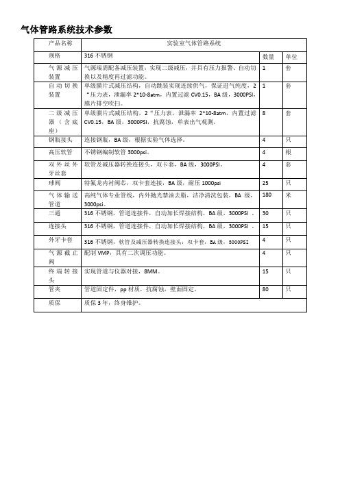
气体管路系统技术参数
15
只
管夹
管道固定件,pp材质,抗腐蚀,壁面固定。
80
只
质保
质保3年,终身维压结构,自动跳装实现连续供气,保证进气纯度,2“压力表,泄漏率2*10-8atm,内置过滤CV0.15,BA级,3000PSI,膜片排空吹扫。
1
套
二级减压器(含底座)
单级膜片式减压结构,2“压力表,泄漏率2*10-8atm,内置过滤CV0.15,BA级,3000PSI,抗腐蚀,单表出气观测。
180
米
三通
316不锈钢,管道连接件,自动加长焊接结构,BA级,3000PSI。
30
只
连接头
316不锈钢,管道连接件,自动加长焊接结构,BA级,3000PSI。
15
只
外牙卡套
316不锈钢,软管及减压器转换连接头,双卡套,BA级,3000PSI
4
只
气源截止阀
配制VMP,具有二次调压功能。
4
只
终端转接头
气体管路系统技术参数产品名称实验室气体管路系统规格316不锈钢数量单位气源减压装置气源端需配备减压装置实现二级减压并具有压力报警自动切换以及精度再过滤功能
气体管路系统技术参数
产品名称
实验室气体管路系统
规格
316不锈钢
数量
单位
气源减压装置
气源端需配备减压装置,实现二级减压,并具有压力报警、自动切换以及精度再过滤功能。
8
套
钢瓶接头
连接钢瓶,BA级,根据实验气体选择。
4
只
高压软管
不锈钢编制软管3000psi。
4
根
双外丝外牙丝套
软管及减压器转换连接头,双卡套,BA级,3000PSI。
气体管路方案书
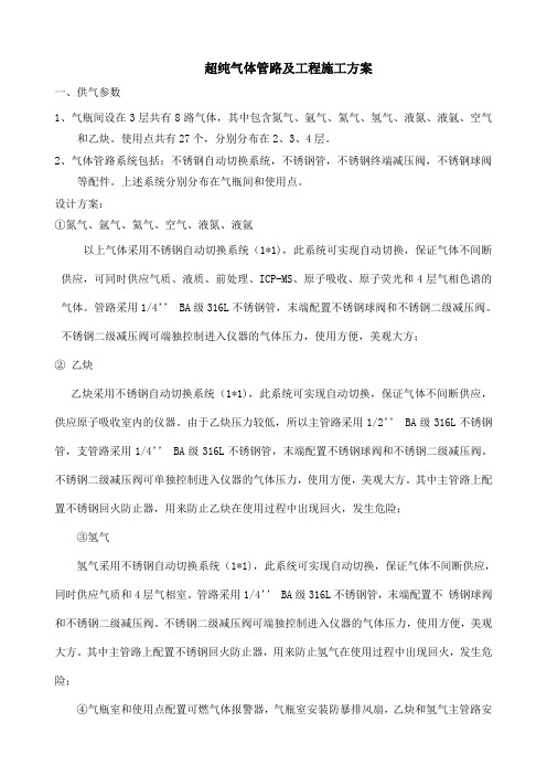
超纯气体管路及工程施工方案一、供气参数1、气瓶间设在3层共有8路气体,其中包含氮气、氩气、氦气、氢气、液氮、液氩、空气和乙炔。
使用点共有27个,分别分布在2、3、4层。
2、气体管路系统包括:不锈钢自动切换系统,不锈钢管,不锈钢终端减压阀,不锈钢球阀等配件。
上述系统分别分布在气瓶间和使用点。
设计方案:①氮气、氩气、氦气、空气、液氮、液氩以上气体采用不锈钢自动切换系统(1*1),此系统可实现自动切换,保证气体不间断供应,可同时供应气质、液质、前处理、ICP-MS、原子吸收、原子荧光和4层气相色谱的气体。
管路采用1/4’’ BA级316L不锈钢管,末端配置不锈钢球阀和不锈钢二级减压阀。
不锈钢二级减压阀可端独控制进入仪器的气体压力,使用方便,美观大方;②乙炔乙炔采用不锈钢自动切换系统(1*1),此系统可实现自动切换,保证气体不间断供应,供应原子吸收室内的仪器。
由于乙炔压力较低,所以主管路采用1/2’’ BA级316L不锈钢管,支管路采用1/4’’ BA级316L不锈钢管,末端配置不锈钢球阀和不锈钢二级减压阀。
不锈钢二级减压阀可单独控制进入仪器的气体压力,使用方便,美观大方。
其中主管路上配置不锈钢回火防止器,用来防止乙炔在使用过程中出现回火,发生危险;③氢气氢气采用不锈钢自动切换系统(1*1),此系统可实现自动切换,保证气体不间断供应,同时供应气质和4层气相室。
管路采用1/4’’ BA级316L不锈钢管,末端配置不锈钢球阀和不锈钢二级减压阀。
不锈钢二级减压阀可端独控制进入仪器的气体压力,使用方便,美观大方。
其中主管路上配置不锈钢回火防止器,用来防止氢气在使用过程中出现回火,发生危险;④气瓶室和使用点配置可燃气体报警器,气瓶室安装防暴排风扇,乙炔和氢气主管路安装防暴电磁阀。
当可燃气体出现泄漏时,可燃气体报警器进行声光报警,同时联动防暴排风扇和防暴电磁阀,防暴排风扇自动开启,防暴电磁阀关闭。
⑤气瓶室氮气、氩气、氦气、空气、乙炔、氢气六种气体分别安装低压报警装置。
气体管路施工技术要求及验收标准
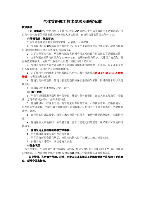
气体管路施工技术要求及验收标准技术要求(1)总体设计:管道采用1/4”外径,经过AP处理的专用高等级洁净不锈钢管道。
所有集中在气瓶柜的管路有适当的路径进入各实验桌,在使用仪器的附近接气体考克。
(2)管路设计、规划要点:气体管路系统应具有良好的气密性,可靠性,可维护性。
1、气瓶阀出口为GB标准的外螺纹形式,为了便于管路系统与气瓶连接,故从气瓶阀出口到管道系统应设有转换接头(气瓶接头)。
2、为了方便更换气瓶,从上述气瓶接头到调节阀之间应设有耐高压的不锈钢螺旋管。
3、由于气瓶内部的气体压力为150Bar左右,使用点的压力较小,气体压力有变化,而且数值差距较大,故应在气瓶出口处设置一级减压阀(双表头)。
4、气路系统中应设有在紧急情况下能够快速切断供气的装置—开关阀,为了开关系统的方便和快捷,本项目中开关阀采用球阀。
5、为了保持气体的纯度及管道系统的气密性,所有管道采用进口BA级316L不锈钢管道,内表面按规定处理。
6、管道与阀件的连接,管道与管道的连接应保证系统的气密性,同时要便于维修及更换阀件。
7、管道固定件要求坚固,轻巧,耐用。
(3) 施工要求:1、所有不锈钢管道两端用塑料盖密封,外部有塑料套密封,在进入施工现场后,安装前,方可将塑料套拆封,并除去塑料盖。
2、管道铺设时,应注意平直,弯管处采用专用弯管器,不得徒手弯曲,切断管道时,用专用切管器操作,严禁用锯子锯断管道。
管道切断后,应用专用工具处理断口,严禁用普通锉刀处理。
3、在管道的行进路线中,每隔l米应设置一组管夹,如遇特殊建筑物结构,应酌情考虑。
4、管道穿墙及穿地板时,应设置套管,套管与管道之间的空隙,应采用不可燃烧的材料填充。
5、管道采用全自动焊机焊接方式衔接。
6、所有螺纹连接处应采用密封带密封。
7、所有系统部件安装完毕后,应用高纯氮气进行三遍以上的大流量吹扫。
8、在整个施工过程中,应注意施工安全。
(4)验收说明施工结束后,用高纯氮气进行检漏保压测试,测试压力应为工作压力的1.25倍。
- 1、下载文档前请自行甄别文档内容的完整性,平台不提供额外的编辑、内容补充、找答案等附加服务。
- 2、"仅部分预览"的文档,不可在线预览部分如存在完整性等问题,可反馈申请退款(可完整预览的文档不适用该条件!)。
- 3、如文档侵犯您的权益,请联系客服反馈,我们会尽快为您处理(人工客服工作时间:9:00-18:30)。
1、概述
中央化验室气体管路技术规格书
本技术规格书所描述的使用范围为国电英力特煤基多联产工程中央实验室的气体管路。
包含所有用气房间气体管路的安装、技术指导、培训等一系列交钥匙外包工程。
2、供货范围
报价方必须提供但不限于涉及到本项目中央化验室所用到的一切与气路气体(不包括标准气)输送相关的管路、阀件及其配套和中央化验室的一切管道、净化器、过滤器等。
3、气体管路技术要求
3.1总体要求
气体管路总体要求布局简单合理,安全无泄露,易于操作,易于检查和维护。
3.2管路要求
材质:中央化验室可以采用无缝不锈钢管。
管径:主管线和支路管线管径必须根据用气量科学换算进行管径选择。
净化:气体管路必须经酸洗脱脂处理,管路上必须有气体净化处理装置。
3.3阀件要求
阀件材质应跟其安装位置的管道材质保持一致。
气瓶间主管道必须有止回阀、安全阀和开关阀。
3.4气瓶间管路要求
气瓶间气瓶供气必须采用多瓶并联供气系统供气。
氢气、乙炔气管路应符合相关规范;氮气管路要有工业氮气和钢瓶氮气切换装置;氩气管线要有工艺氩气和钢瓶氩气切换装置,每路气体管线必须有气体低压/高压报警装置。
3.5用气点要求
在每个用气点必须有截止阀,报价方必须负责用气点和仪器的连接管路和转换接头的供货。
每个通风柜均要接氮气作为保护气,报价方提供通风柜内气体管路、转换接头和气体考克的提供。
在必要的房间必须提供仪表空气接口,报价方提供吹扫管路和吹扫枪等。
由于色谱间用气点多,布局复杂,对气体压力和流量波动控制要求严格,报价方必须提供能够稳压稳流的布局方案和设备。
