日立变频器操作说明 SJ
日立SJ300-EL系列变频器中文操作手册
日立SJ300-EL系列变频器中文操作手册日立SJ300-EL系列变频器中文操作手册1.简介1.1 变频器概述1.2 主要特性2.安装与连接2.1 安装环境要求2.2 变频器接线2.3 外部设备连接3.参数设置3.1 参数概述3.2 参数调整方法4.运行与操作4.1 变频器启停4.2 运行状态监控4.3 故障报警与处理5.编程与调试5.1 编程概述5.2 编程步骤5.3 调试方法6.远程控制与通信6.1 远程控制方法6.2 通信设置7.维护与保养7.1 维护要求7.2 保养措施7.3 故障排除与维修8.附件8.1 SJ300-EL系列变频器安装图纸8.2 SJ300-EL系列变频器技术参数表9.法律名词及注释9.1 变频器:一种能够通过调整输送电力频率实现电动机转速控制的设备。
9.2 接线:将变频器与电动机及信号源进行正确的电气连接。
9.3 故障报警:变频器检测到异常情况后发出的警报信号。
9.4 编程:根据需要设置与控制变频器的参数。
9.5 通信设置:通过网络或其他通信方式连接变频器与外部设备,并进行相应的设置。
本文档涉及附件:1.SJ300-EL系列变频器安装图纸2.SJ300-EL系列变频器技术参数表本文所涉及的法律名词及注释:1.变频器:一种能够通过调整输送电力频率实现电动机转速控制的设备。
2.接线:将变频器与电动机及信号源进行正确的电气连接。
3.故障报警:变频器检测到异常情况后发出的警报信号。
4.编程:根据需要设置与控制变频器的参数。
5.通信设置:通过网络或其他通信方式连接变频器与外部设备,并进行相应的设置。
变频器操作说明

变频器操作说明操作说明:变频器一、概述变频器是一种用于改变电机工作频率和电压的设备,以实现电机的调速控制。
本文将详细介绍变频器的操作步骤和注意事项。
二、操作步骤1. 连接电源:将变频器的电源线与电源连接,确保电源接线正确牢固。
2. 连接电机:将电机的线缆与变频器的电机输出端相连,确保电机与变频器连接稳固可靠。
3. 设置参数:通过变频器的控制面板或者外部控制器,设置合适的电机工作频率和电压。
4. 启动变频器:按下变频器的启动按钮,观察变频器面板上的指示灯是否变亮,确认变频器已启动。
5. 调节速度:通过变频器面板上的旋转按钮或者按键,调节电机的运行速度。
一般来说,旋转按钮向右转动会增加速度,向左转动会减小速度。
6. 停止变频器:按下变频器的停止按钮,等待电机完全停止后,断开电源连接。
三、注意事项1. 安全操作:在使用变频器时,确保已按照电器安全规范进行安装和接线。
在操作变频器过程中,避免触摸带电部件,以免发生电击事故。
2. 工作环境:变频器应放置在通风良好、干燥无尘的环境中,避免暴露于高温、潮湿或有腐蚀性气体的场所。
3. 参数设置:根据实际需求,正确设置变频器的参数。
不同的工作负载和运行环境需要调整不同的参数,以达到最佳运行效果。
4. 过载保护:如果变频器负载过大或出现故障,变频器会通过内置的过载保护功能自动停止工作,避免损坏设备和危险事故的发生。
5. 维护保养:定期检查变频器的散热器是否清洁,如有灰尘应及时清理。
同时,注意防护装置是否完好,必要时进行维修和更换。
四、应用范围变频器广泛应用于工业生产中的电机控制系统,特别是对于需要频繁调速的设备,如电梯、风机、水泵等。
通过灵活的调速控制,可以提高设备的运行效率和能源利用率,降低设备维护成本。
五、总结本文介绍了变频器的操作步骤和注意事项,希望能够帮助读者正确、安全地使用变频器。
在操作过程中,务必遵循相关的操作规范和安全要求,以确保设备的正常运行和人身安全。
日立SJ100系列变频器快速参考手册说明书
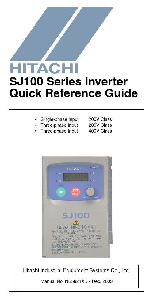
•Single-phase Input 200V Class •Three-phase Input 200V Class •Three-phase Input400V ClassManual No. NB5821XD • Dec. 2003Hitachi Industrial Equipment Systems Co., Ltd.HITACHISJ100 Series Inverter Quick Reference GuideCaution: Be sure to read the SJ100 Inverter Manual andfollow its Cautions and Warnings for the initial productinstallation. This Quick Reference Guide is intended forreference use by experienced users in servicing existinginstallations.Power Circuit Terminals–002NFE/NFU, –004NFE/NFU, –005NFEJumper+1L1L2N/L3U/T1V/T2W/T3ChassisGround–007 to 022NFE/NFU, –037LFU, 004 to 040HFE/HFUJumper+1L1L2N/L3U/T1V/T2W/T3ChassisGround–055LFU, –075LFU, 055HFE/HFU, 075HFE/HFU Jumper+1L1L2N/L3U/T1V/T2W/T3ChassisGroundControl Circuit TerminalsTerminalName Description Ratings and NotesP24+24V for logic inputs24VDC supply, 30 mA max.(Notes: Do not use for network powerDo not short to terminal L)1, 2, 3, 4, 5, 6Intelligent (program-mable) discrete logicinputs 27VDC max. (use P24 or an external supply referenced to terminal L), 4.7k Ω input impedanceL (top row)GND for logic inputs Sum of input 1 to 6 currents (Note: Do not ground)11, 12Discrete logic outputs 50 mA max. ON current,27 VDC max. OFF voltage CM2Common for logic outputs 100 mA max for sum of terminals 11 and 12 currents FMPWM output0 to 10VDC, 1 mA max., 50% duty cycle L (bottom row)Common for analog inputs Sum of OI, O, and H currents (return)OIAnalog input, current4 to 19.6 mA range, 20 mA nominalH O OI FM P24L Analog inputsAnalog outputsAlarm relayLogic outputsLogic inputsL 654321CM21211AL0AL1AL2OAnalog input, voltage0 to 9.6 VDC range, 10VDC nominal, 12VDC max., input impedance 10 k ΩH +10V analog reference 10VDC nominal, 10 mAmax.AL0Relay common contact Contact rating Max resistive load = 250V AC, 2.5A; 30VDC 3A;Max inductive load = 250V AC, 0.2A; 30VDC 0.7AMinimum load = 5VDC 100mA,100V AC 10mAAL1Relay contact, normally closed during RUN AL2Relay contact,normally open during RUNTerminal NameDescription Ratings and NotesBasic Wiring DiagramThe following wiring diagram shows the power and motor connec-tions for basic operation. The optional signal input wiring supports external Fwd and Rev Run command, and a speed potentiometer.(L1)R (L2)S (N/L3)T(T2)V(T3)W(T1)U MotorForwardLOHReverseAlarm contacts, 1 Form CRun signalFrequency arrival signal Open collector outputs:External speed reference pot.SJ100From 3-phase power input source (See specifications label on inverter for details)Logic output commonLoadLoadAnalog common Analog referenceP2421CM21211AL0AL1AL2Inputs:Inverter Keypad Operation•Run/Stop LED – ON when the inverter output is ON and the motor is developing torque, and OFF when the inverter output is OFF (Stop Mode).•Program/Monitor LED – ON when the inverter is ready for parameter editing (Program Mode). It is OFF when the parameter display is monitoring data (Monitor Mode).•Run Key Enable LED – ON when the inverter is ready to respond to the Run key, OFF when the Run key is disabled.•Run Key – Press this key to run the motor (the Run Enable LED must be ON first). Parameter F_04, Keypad Run Key Routing, determines whether the Run key generates a Run FWD or Run REV command.•Stop/Reset Key – Press this key to stop the motor when it is running (uses the programmed deceleration rate). This key will also reset an alarm which has tripped.(continued, next page...)Hz POWER ARUN PRGMINMAXHITACHIFUNC.STR1250.0Parameter Display Run/Stop LEDProgram/Monitor LEDRun Key Enable LEDRun Key Power LEDDisplay Units LEDs Hertz AmperesPotentiometer Enable LED Potentiometer Stop/Reset KeyFunction KeyUp/Down Keys Store Key•Potentiometer – Allows an operator to directly set the motor speed when the potentiometer is enabled for output frequency control.•Potentiometer Enable LED – ON when the potentiometer is enabled for value entry.•Parameter Display – A 4-digit, 7-segment display for parame-ters and function codes.•Display Units: Hertz/Amperes – One of these LEDs will be ON to indicate the units associated with the parameter display.•Power LED – ON when the power input to the inverter is ON.•Function Key – This key is used to navigate through the lists of parameters and functions for setting and monitoring parameter values.•Up/Down Keys – Use these keys alternately to move up or down the lists of parameter and functions shown in the display, and to increment/decrement values.•Store Key – When the unit is in Program Mode and the operator has edited a parameter value, press the Store key to write the new value to the EEPROM.Keypad Navigation Maph 34h 0112c 91c 0112b 92b 0112A 98A 0112121212H ––12C ––12b ––12A ––F 04F 0112d 09d 0112o.0123.4Edit12Increment/decrement valueWrite datato EEPROMDisplay dataMonitor Mode Program Mode12FUNC.STRFUNC.FUNC.12Return to parameter listFUNC.FUNC.Select ParameterEdit ParameterStore as powerup defaultpowerdownPowerup TestThe Powerup Test procedure uses minimal parameter settings to run the motor. The procedure describes two alternative methods for commanding the inverter: via the inverter keypad, or via the logic terminals.•Check power input and motor output wiring (see page4 diagram).•If using logic terminals for testing, verify correct wiring on [P24], [FW], [H], [O], and [L] (bottom row) per the diagram on page4.•Reverse [RV] input wiring (defaults to terminal [2]) is optional.Step Description Via Keypad Via LogicTerminals1Set speed command source setting A_01 = 00(keypad pot.)A_01 = 01,[H–O–L] input2Set Run FW command source A_02 = 02(Run key)A_02 = 01,[FW] input3Set Run REV command source —C_02 = 01,[RV] input4Set motor base freq.A_03 = 605Set motor poles(2 / 4 / 6 / 8)H_04 = 4 (default), change only if your motor is different6Set keypad display to monitor freq.Access D_01, press Func key, display will show 0.0Perform safety check Disconnect load from motor7Turn keypad pot.to MIN position Ensure voltage on [O]—[L] termi-nals= 0V8Run Forward command Press Run key Turn ON the[FW] terminal9Increase speed Rotate keypadpot. CW dir.Increase voltage at [O]10Decrease speed Rotate keypadpot. CCW dir.Decrease voltage at [O]11Stop motor Press Stop key Turn OFF the[FW] terminal12Run Reverse command (optional)—Turn ON the [RV]terminal13Stop motor—Turn OFF the[RV] terminalError CodesThe SJ100 series inverters will trip on over-current, over-voltage, and under-voltage to protect the inverter. The motor output turns OFF, allowing the motor to free-run to a stop. Press the Stop/Reset key to reset the inverter and clear the error.Basic Error CodesErrorCode Name Probable Cause(s)E01Over current event whileat constant speed •Inverter output was short-circuited •Motor shaft is locked•Load is too heavy•A dual-voltage motor is wired incorrectlyNote: The SJ100 will over current trip at nominally 200% of rated currentE02Over current event duringdecelerationE03Over current event duringaccelerationE04Over current event forother conditions •DC braking power(A_54) set too high•Current transformer / noise errorE05Overload protection•Motor overload is detected by theelectronic thermal functionE06Braking resistor overload•Regenerative braking resistorexceeds the usage time or usage ratio E07Over voltage protection•DC bus voltage exceeds a threshold,due to regenerative energy from motor E08EEPROM error•Built-in EEPROM memory experi-enced noise, high temperature, etc. E09Under-voltage error•DC bus voltage decreased enough tocause a control circuit faultE10CT error(current transformer)•High electrical noise near inverter •A fault occurred in the built-in CTE11E22CPU error•Built-in CPU had internal error E12External trip•[EXT] input signal detectedE13USP (Unattended StartProtection)•When (USP) was enabled, an error occurred when power was applied while a Run signal was presentE14Ground fault•A ground fault was detectedbetween the inverter output and themotor. This feature protects theinverter, and does not protect humans.Error Trip ConditionsUse function code D_08 to access the error trip conditions for the current error as shown in the table below. Use the Up and Down arrow keys to scroll through the trip condition parameters.E15Input over-voltage •Input voltage was higher than the specified value, 60 sec. after powerup E21Inverter thermal trip •Inverter internal temperature is above the thresholdE35Thermistor•Thermistor input, [THM] and [L], is over the temp. threshold---Under-voltage (brown-out) with output shutoff•Low input voltage caused theinverter to turn OFF the motor output and try to restart. If unsuccessful, a trip occurs.StepDisplay1. Access D_08d 082. Press Function KeyIf no error:_ _ _If error exists:Exx(error code)3. Press Up/Dn key (if error exists)Output frequency at trip point:10.0Motor current at trip point:0.025DC bus voltage at trip point:189.8Error CodeNameProbable Cause(s)12Restoring Factory Default SettingsActionDisplayFunction/ParameterPress ,or as needed.b --“B” Group selectedPress .b 01First “B” Group parame-terPress/holduntil...b 85Country code forinitialization selected Press . If setting iscorrect, then skip next step.0200 = Japan 01 = Europe02 = United StatesTo change country code, press or to set; to store.Press .b 85Country code forinitialization selected Press .b 84Initialization function selectedPress .000 = disable initialization, clear trip history only Press .011 = enable initialization Press .b 84Initialization now enabled to restore all defaultsPress/hold , ,and . Do not release yet.b 84First part of key sequencePress/hold (STOP)for 3 seconds, then release.d 00Final part of special sequence, “D_00” is flashingNow release the all keys together, only after “D_00” display begins blinking.EU USA JP Default parameter country code shown during initializationInitialization is complete.d 01Function code for output frequency monitor shownFUNC.12FUNC.1FUNC.12STR FUNC.2FUNC.1STR FUNC.12Note: After initializing the inverter, use the Powerup Test on page 8 to get the motor running again.Parameter Tables“D” Group: Monitoring FunctionsFunc. Code Name / DescriptionUnits D_01Output frequency monitor Hz D_02Output current monitor A D_03Rotation direction monitor—D_04Process variable (PV), PID feedback monitor %D_05Intelligent input terminal status—D_06Intelligent output terminal status—D_07Scaled output frequency monitor(output frequency x B_86 scale factor)User-defined D_08Trip event monitor —D_09Trip history monitor—DirectionForward Stop Reverse214365Terminal NumbersON OFF1211AL Terminal NumbersON OFFTrip History Navigation MapE 0760.0124.00270.01212d 0812o.0Display dataMonitor Mode12FUNC.FUNC.d 09____NoError code Output frequency at trip point Motor current at trip point DC bus voltage at trip pointFUNC.Y esNo errorError (n-1) exists?NoY esE 03E 05____No historyFUNC.Error (n-2) exists?NoY esFUNC.____FUNC.FUNC.12FUNC.No historyError exists?Parameter tables for user-settable functions follow these conven-tions:•Some parameters have 2nd motor equivalents, indicated by the x2xx parameter codes in the left-most column.•Some parameters specify an option code. Where applicable, the options codes will be in a bulleted list in the Name/Description column.•The default values apply to all models unless otherwise noted for each parameter... –FE (Europe) / – FU (U.S.) / –FR (Japan).•Some parameters cannot be edited during Run Mode, and certain Software Lock settings (B_31) can prohibit all edits. If in doubt, place the inverter in Stop Mode or consult the inverter manual for details.“F” Group: Main Profile Parameters“A” Group: Standard FunctionsFunc. Code Name / DescriptionDefaultValue Set ValueF_01Output frequency setting 0.0F_02Acceleration (1) time setting10.0F202Acceleration (1) time setting, 2nd motor 10.0F_03Deceleration (1) time setting10.0F203Deceleration (1) time setting, 2nd motor 10.0F_04Keypad Run key routing •00Forward •01Reverse00Func. Code Name / DescriptionDefault Value –FE / –FU /–FR Set ValueA_01Frequency source setting •00Keypad potentiometer •01Control terminal•02Function F_01 setting01 / 01 / 00A_02Run command source setting•01Input terminal FW or RV (assign-able)•02Run key on keypad, or digitaloperator01 / 01 / 02A_03/ A203Base frequency setting50.0 / 60.0 /60.0A_04/ A204Maximum frequency setting50.0 / 60.0 /60.0A_11O/OI–L input active range startfrequency0 A_12O/OI–L input active range end frequency0 A_13O/OI–L input active range start voltage0 A_14O/OI–L input active range end voltage100 A_15O/OI–L input start frequency enable•00Use A_11 starting value)•01Use 0 Hz01A_16External frequency filter time constant8 A_20/A220Multi-speed frequency setting0A_21 A_22 A_23 A_24 A_25 A_26 A_27 A_28 A_29.. ..A_35Multi-speed frequency settings(for both motors)0 / 0 / 50 / 0 / 100 / 0 / 150 / 0 / 200 / 0 / 300 / 0 / 400 / 0 / 500 / 0 / 600 / 0 / 00 / 0 / 0A_38Jog frequency setting 1.0 A_39Jog stop mode•00Free-run stop, jogging disabledduring motor run•01Controlled deceleration, joggingdisabled during motor run•02DC braking to stop, joggingdisabled during motor run00A_41/ A241Torque boost method selection•00Manual torque boost•01Automatic torque boost00A_42/A242Manual torque boost value11A_43/ A243Manual torque boost frequency adjust-ment10.0A_44/ A244V/f characteristic curve selection•00V/f constant torque•01V/f variable torque•02Sensorless vector control02A_45V/f gain setting100 A_51DC braking enable•00Disable•01Enable00 A_52DC braking frequency setting0.5 A_53DC braking wait time0.0 A_54DC braking force during deceleration0 A_55DC braking time for deceleration0.0 A_61Frequency upper limit setting0.0 A_62Frequency lower limit setting0.0 A_63A_65A_67Jump (center) frequency setting0.0A_64 A_66 A_68Jump (hysteresis) frequency widthsetting0.5A_71PID Enable•00PID operation OFF•01PID operation ON00A_72PID proportional gain 1.0A_73PID integral time constant 1.0A_74PID derivative time constant0.0A_75PV scale conversion 1.00A_76PV source setting•00[OI] terminal (current input)•01[O] terminal (voltage input)00A_81A VR function select•00A VR enabled•01A VR disabled•02A VR enabled except during decel02 / 00 / 02A_82A VR voltage select230/230/200400/460/400 A_92/A292Acceleration (2) time setting15.0“B” Group: Fine-tuning FunctionsA_93/A293Deceleration (2) time setting15.0A_94/A294Select method to switch to Acc2/Dec2 profile•002CH input from terminal •01transition frequency00A_95/A295Acc1 to Acc2 frequency transition point 0.0A_96/A296Dec1 to Dec2 frequency transition point 0.0A_97Acceleration curve selection •00Linear •01S-curve •02U-shape •03Reverse U-shape 00A_98Deceleration curve selection •00Linear •01S-curve •02U-shape••03ReverseU-shape00Func. Code Name / DescriptionDefault Value –FE / –FU /–FRSet ValueB_01Selection of automatic restart mode •00Alarm output after trip, automatic restart disabled •01Restart at 0Hz•02Resume operation after frequency matching•03Resume previous freq. after freq. matching, then decelerate to stop and display trip info00B_02Allowable under-voltage power failure time1.0B_03Retry wait time before motor restart1.0B_12/ B212Level of electronic thermal setting Ratedcurrent ofeach inverterB_13/ B213Electronic thermal characteristic•00Reduced torque•01Const. torque01 / 01 / 00B_21Overload restriction operation mode•00Disabled•01Enabled for accel and constantspeed•02Enabled for constant speed only01B_22Overload restriction setting Ratedcurrentx 1.25 B_23Deceleration rate at overload restriction 1.0B_31Software lock mode selection•00Low-level access, [SFT] blocksedits•01Low-level access, [SFT] blocksedits (except F_01 and Multi-speedparameters)•02No access to edits•03No access to edits except F_01 andMulti-speed parameters01B_81[FM] terminal analog meter adjustment80B_82Start frequency adjustment0.5B_83Carrier frequency setting 5.0 / 5.0 /12.0B_84Initialization mode (parameters or triphistory)•00Trip history clear•01Parameter initialization00B_85Country code for initialization•00Japan version•01Europeversion•02US version01 / 02 / 00B_86Frequency scaling conversion factor 1.0B_87STOP key enable•00Enable•01Disable00B_88Restart mode after FRS•00Restart from 0Hz•01Restart from frequency detectedfrom actual speed of motor00“C” Group: Intelligent Terminal FunctionsB_89Data select for digital operator OPE-J •01Output frequency (D_01)•02Output current (D_02)•03Motor direction (D_03)•04PID PV feedback (D_04)•05Input states for input terminals (D_05)•06Output states for output terminals (D_06)•07Scaled output frequency (D_07)01B_90Dynamic braking usage ratio 0.0B_91Stop mode selection00B_92Cooling fan control •00Fan always ON•01Fan ON during Run, OFF during Stop00Func. Code Name / DescriptionDefault Value –FE / –FU /–FRSet ValueC_01Terminal [1] function Nineteen option codes available (see page 22)00C_02Terminal [2] function 01C_03Terminal [3] function 02 / 16 / 02C_04Terminal [4] function 03 / 13 / 03C_05Terminal [5] function 18 / 09 / 09C_06Terminal [6] function 09 / 18 / 18C_11Terminal [1] active state•00Normally open [NO]•01Normally closed [NC]00C_12Terminal [2] active state00C_13Terminal [3] active state00C_14Terminal [4] active state•00Normally open [NO]01Normally closed [NC]00 / 01 / 00C_15Terminal [5] active state00C_16Terminal [6] active state00C_21Terminal [11] function Six option codes available (see page 22)01C_22Terminal [12] function 00C_24Alarm relay terminal function05C_23[FM] signal selectionThree option codes available (see page 23)00C_31Terminal [11] active state (–FU)•00Normally open (NO)•01Normally closed (NC)— / 00 / —Reserved (–FE / –FR)00 / — / 00C_32Terminal [12] active state (–FU)— / 00 / —Terminal [11] active state (–FE / –FR)00 / — / 00C_33Alarm relay terminal active state01C_41Overload level settingRated current of inverter C_42Frequency arrival setting for accel 0.0C_43Arrival frequency setting for decel 0.0C_44PID deviation level setting 3.0C_81O input span calibration Factory calibrated C_82OI input span calibrationC_91Debug mode enable •00Display •01No display 00C_92Core monitor address (reserved)0000C_93Core monitor date (reserved)—C_94Core set address (reserved)D001C_95Core set date (reserved)00Func. Code Name / DescriptionDefault Value –FE / –FU /–FR Set Value“H” Group: Motor Constants FunctionsFunc.Code Name / DescriptionDefaultValue–FE / –FU /–FRSetValueH_01Auto-tuning Setting•00Auto-tuning OFF•01Auto-tune (measure motor resis-tance and inductance, without rotating)•02Auto-tune (rotate motor)00H_02/ H202Motor data selection•00Standard motor data•01Auto-tuning data•02Adaptive tuning data00H_03/H203Motor capacity Factory setH_04/ H204Motor poles setting•2 poles•4 poles•6 poles•8 poles4H_05/H205Motor speed constant20H_06/H206Motor stabilization constant100H_20/ H220Motor constant R1InverterratingH_21/ H221Motor constant R2InverterratingH_22/ H222Motor constant L InverterratingH_23/ H223Motor constant I0InverterratingH_24/ H224Motor Constant J InverterratingH_30/ H230Auto-tuned motor constant R1InverterratingH_31/ H231Auto-tuned motor constant R2InverterratingH032/ H232Auto-tuned motor constant L InverterratingH_33/ H233Auto-tuned motor constant I0InverterratingH_34/ H234Auto-tuned motor constant J InverterratingIntelligent Input Terminal ListingSymbol Code Input Terminal NameFW00Forward Run/StopRV01Reverse Run/StopCF102Multi-speed select, Bit 0 (LSB)CF203Multi-speed select, Bit 1CF304Multi-speed select, Bit 2CF405Multi-speed select, Bit 3 (LSB)JG06JoggingDB07External DC brakingSET08Set (select) second motor data2CH092-stage accel and decelFRS11Free-run stopEXT12External tripUSP13Unattended start protectionSFT15Software lockAT16Analog input voltage/current sel.RS18Reset inverterPTC19PTC thermistor thermal protectionUP27Remote control Up func.DWN28Remote control Down func.Intelligent Output Terminal ListingSymbol Code Input Terminal NameRUN00Run signalFA101Freq. arrival type 1 – constant speedFA202Freq. arrival type 2 – over-frequencyOL03Overload advance notice signalOD04Output deviation for PID controlAL05Alarm signalAnalog Input ConfigurationThe following tables show the parameter settings required for vari-ous analog input signal types.Analog Output Function ListingThe following table shows all three functions available for assign-ment to the analog output terminal:•Terminal [FM], option set by C_23Auto-tuning ProcedureThe SJ100 auto-tuning feature calibrates the inverter to the parame-ters of a specific motor such as winding resistance and reactance. For optimum sensorless vector control, it is important to auto-tune during the initial installation, and after replacing either the motor or the inverter.Auto-tuning requires that you configure the inverter for SLV control (set A_44 = 02). Then you can perform the auto-tuning procedure, which is detailed in the SJ100 Inverter Instruction Manual.[AT]External Frequency Command InputOFF [O] — [L]ON[OI] — [L](not assigned to any inputterminal)Summation of [O] — [L] and [OI] — [L]Option Code Function Name Description Corresponding Signal Range 00Output frequency Actual motor speed, represented by PWM signal0 to max. freq. in Hz01Output currentMotor current (% of maximum rated output current), represented by PWM signal0 to 200%02Digital output frequencyOutput frequency 0 to max. freq. in Hz。
变频器操作说明
引言概述:正文内容:一、变频器的基本操作步骤1.1供电和连接:将变频器与电源连接,并确保供电电源稳定。
注意接线的正确性,以避免电路短路或其他安全问题。
1.2开机和复位:按下变频器的开关按钮,启动变频器。
同时,进行系统的复位,将所有参数恢复到出厂设置。
1.3设定运行模式:根据实际需求,选择适当的运行模式。
常见的运行模式包括手动、自动和外部控制模式等。
1.4设置运行参数:根据设备的特点和工作要求,调整变频器的运行参数。
包括频率、电流、转速等参数的设置。
1.5监控和调试:启动运行后,定期监控变频器的运行状态,及时发现和解决问题。
同时,进行必要的调试,以保证系统的正常运行。
二、变频器参数的设置和调整方法2.1频率设置:根据实际工况,合理设置变频器的输出频率。
同时,需要考虑电机类型、负载特性等因素。
2.2电压和电流设置:根据电机的额定电压和电流参数,设置变频器的输出电压和电流。
确保电机的正常运行。
2.3加速和减速曲线设置:调整变频器的加速和减速曲线,使电机在启动和停止过程中能够平稳运行,避免冲击和损坏。
2.4制动设置:对于某些需要快速制动的设备,需要设置制动模式和制动电阻,确保设备能够快速停止。
2.5通信设置:对于需要与其他设备进行通信的系统,需要设置通信参数,以实现设备之间的数据交互和控制。
三、变频器的故障排除和维护3.1常见故障类型:介绍常见的变频器故障类型,包括过载、短路、过热等,并分析故障原因。
3.2故障排除步骤:提供一般性的故障排除步骤,包括排查故障现象、分析故障原因、采取合适的措施解决故障。
3.3维护和保养:介绍变频器的定期维护和保养措施,包括清洁、检查连接线路、定期更换电解电容等。
四、变频器在不同应用场景的操作说明4.1电梯变频器的操作:详细介绍电梯变频器的操作步骤和注意事项,确保电梯的安全和正常运行。
4.2水泵变频器的操作:阐述水泵变频器的操作方法,包括自动控制、远程控制等功能,以及应对突发故障的措施。
日立变频器SJ 系列彩 手册
!"#$%&'(
!"#$
!"
!" !"#$%&'()*(+,-
!"#
!"#$
!"#$%&
•
!"#$%&'
!"#$%&
!"# SJ300
!"#$%&'()*
!"#$
!"#$%&'(
!"#$ !"#
!"#SRW
SJ300
!"#$%
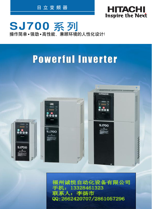
SJ700
!"#$%&'()
•
!"#$%&'()*
!"12
!""#$
!
!"
通用 模拟量输入
XA(0): 0~10V(O端子) XA(1): 4~20mA(OI端子) XA(2): 0~10V(O2端子)
通用输出端子 最大6点<Y(00)~Y(05)>
通用 模拟量输出
YA(0):可分配到FM端子 YA(1):可分配到AM端子 YA(2):可分配到AMI端子
程序控制命令(循环、无条件分支、条件分支、时间控制、子程序、其他)
(SJ700-
)
007HFEF2 015HFEF2 022HFEF2 040HFEF2 055HFEF2 075HFEF2 110HFEF2 150HFEF2 185HFEF2 220HFEF2 300HFEF2 370HFEF2 450HFEF2 550HFEF2
007HFUF2 015HFUF2 022HFUF2 037HFUF2 055HFUF2 075HFUF2 110HFUF2 150HFUF2 185HFUF2 220HFUF2 300HFUF2 370HFUF2 450HFUF2 550HFUF2
日立 SJ100系列 变频器 说明书
输入
%值
A14
10V 20mA
A11
A15=01
0 Hz
0V 4mA
A13
输入
A14
10V 20mA
%值
DOP,DRW,DOP+ EU/ US
3-12
A US
DOP,DRW,DOP+ EU/
A
DOP,DRW,DOP+
EU/
US
V/F
3-13
V 100%
A42=11
11.8%
A
0 6.0Hz 30.0Hz A43=10%
PRG
POWER Hz A
RUN
STOP RESET
MIN
MAX
/
2-26
10 10. 10
/
/
STOP RESET
RUN
FUNC
3
3-2
3-3
HITACHI
RUN
PRG
POWER Hz A
RUN
STOP RESET
MIN
MAX
FUNC 1
2 STR
/ LED / LED
LED /
LED /
B90
3-25
3-26
B
DOP,DRW,DOP+ EU/ US
B US
3-27
DOP,DRW,DOP+ EU/
3-28
C
C
DOP,DRW,DOP+
EU/
US
3-29
C
DOP,DRW,DOP+
EU/
US
3-30
3-31
3-32
B
DOP,DRW,DOP+ EU/ US
东方日立高压变频用户使用手册
东方日立(成都)电控设备有限公司高压大功率变频器HI系列用户使用说明书( Ver.A )目录1.简述 (3)2.变频装置和外部的接口信号列表 (4)3.变频操作 (7)3.1 互锁 (7)3.2 电机速度控制 (7)3.3 启/停变频器的操作流程 (8)4.显示界面 (11)4.1 条形图 (11)4.2 故障显示 (13)4.3 互锁纪录显示 (17)4.4 DIO(输入和输出接触点显示)界面 (18)附:常见故障及处理 (19)1、简述日本日立公司生产的High V oltage Inverter产品是一种交流电机的速度调节控制装置。
变频器的控制方式采用多级PWM叠加技术,结构采用多个变频器单元串联叠加输出的方式。
日立公司的6KV(10KV)系列变频器每相5(8)级单元,变频器输出电压由所有单元输出叠加而成,波形非常接近于正弦波,谐波含量很低,极大的减小了对交流电机的谐波污染。
整套变频装置由旁通柜,变压器柜,功率单元柜和控制柜四部分组成。
在旁通柜内,装有高压断路器和隔离刀闸等,可实现变频和工频的切换,当变频器在运行中发生重故障时,变频器发出变频切换到工频的指令,也可根据需要,人为的切换到工频。
在变压器柜内,装有多重移相变压器,原边绕组采用星形接法,副边绕组采用延边三角形接法和星形接法,可有效的抵消电网中的偶次谐波,并可有效的滤除某些奇次谐波,尽量减少变频器电源的谐波污染,变压器能承受系统过电压和变频装置产生的共模电压以及谐波的影响。
在功率单元柜内装有功率单元,变频器的输出电压为每个单元输出的PWM波形叠加后的输出。
在控制柜内,装有控制各个回路启停的开关和控制各个功率单元协调工作的控制板,以及整套变频装置同外部系统的接口等。
对变频器的启停操作,通过切换开关,既可以通过就地的按钮控制,又可通过远方的DCS控制来完成。
变频装置根据DCS给出的速度调节信号自动的控制电机的转速,并且在就地和远方都可以监视变频装置的状态。
日立可变速驱动器 SJ700B 系列 说明书
日立可变速驱动器日立变频器SJ700B系列阅读完本[使用说明书]后,请妥善保存。
NT907AZ南京日立产机有限公司请求◯请求非常感谢您惠顾“日立变频器”。
本使用说明书记载了日立变频器SJ700B系列本体的使用、维护等内容。
在使用之前,请熟读本使用说明书,并将本使用说明书交于操作或维护人员妥善保管。
请在安装、运行、检查、维护前仔细阅读本使用说明书,并请严格按照说明书中所记载的机器常识、安全信息和注意事项、操作・使用方法等指示内容进行正确操作。
请务必在本使用说明书记载的各种规格范围内使用。
另外,请进行正确的检查和维护,以防患于未然。
使用与本变频器相关的选件产品时,也请仔细阅读相关产品的使用说明书。
另外,请务必将本使用说明书和各选件说明书送至最终用户处。
◯关于本书的使用·本使用说明书所记载的内容有可能不经通知而有变更,敬请谅解。
·由于本使用说明书不再二次提供,因此请予以妥善保存以防丢失。
·请勿擅自转载本使用说明书部分或全部内容。
·本使用说明书是我公司精心制作而成,若发现本使用说明书中有错误,或存在不清楚的地方敬请垂询。
修订履历表No. 修订内容 实施日期 版本号1 中文版初版 2009/09 NT907AZ・此栏之外,单纯的错字・漏字、误记的订正、说明的追加等不进行预先通知。
安全上的注意事项・请安装在金属等不可燃物体上。
否则有火灾危险。
・请勿在附近放置易燃物品。
否则有火灾危险。
・搬运时请勿提其表面盖板或端子台盖板。
否则有掉落和致伤的危险。
・请勿让电线头、焊渣、铁屑、金属丝、垃圾等异物进入。
否则有火灾危险。
・请安装在能够承受本体重量的地方。
否则有掉落和致伤的危险。
・请安装在无振动的垂直壁面上。
否则有掉落和致伤的危险。
・请勿安装和运行有损伤或部件缺损的变频器。
否则有致伤危险。
・请安装在通风良好的房间内,避免阳光直射,避开高温、潮湿、易结露的环境和有灰尘、腐蚀性气体、 爆炸性气体、易燃性气体、切削液的雾气和盐腐蚀等场所。
东方日立高压变频用户使用手册
东方日立(成都)电控设备有限公司高压大功率变频器HI系列用户使用说明书( Ver.A )目录1.简述 (3)2.变频装置和外部的接口信号列表 (4)3.变频操作 (7)3.1 互锁 (7)3.2 电机速度控制 (7)3.3 启/停变频器的操作流程 (8)4.显示界面 (11)4.1 条形图 (11)4.2 故障显示 (13)4.3 互锁纪录显示 (17)4.4 DIO(输入和输出接触点显示)界面 (18)附:常见故障及处理 (19)1、简述日本日立公司生产的High V oltage Inverter产品是一种交流电机的速度调节控制装置。
变频器的控制方式采用多级PWM叠加技术,结构采用多个变频器单元串联叠加输出的方式。
日立公司的6KV(10KV)系列变频器每相5(8)级单元,变频器输出电压由所有单元输出叠加而成,波形非常接近于正弦波,谐波含量很低,极大的减小了对交流电机的谐波污染。
整套变频装置由旁通柜,变压器柜,功率单元柜和控制柜四部分组成。
在旁通柜内,装有高压断路器和隔离刀闸等,可实现变频和工频的切换,当变频器在运行中发生重故障时,变频器发出变频切换到工频的指令,也可根据需要,人为的切换到工频。
在变压器柜内,装有多重移相变压器,原边绕组采用星形接法,副边绕组采用延边三角形接法和星形接法,可有效的抵消电网中的偶次谐波,并可有效的滤除某些奇次谐波,尽量减少变频器电源的谐波污染,变压器能承受系统过电压和变频装置产生的共模电压以及谐波的影响。
在功率单元柜内装有功率单元,变频器的输出电压为每个单元输出的PWM波形叠加后的输出。
在控制柜内,装有控制各个回路启停的开关和控制各个功率单元协调工作的控制板,以及整套变频装置同外部系统的接口等。
对变频器的启停操作,通过切换开关,既可以通过就地的按钮控制,又可通过远方的DCS控制来完成。
变频装置根据DCS给出的速度调节信号自动的控制电机的转速,并且在就地和远方都可以监视变频装置的状态。
日立变频器系列说明书
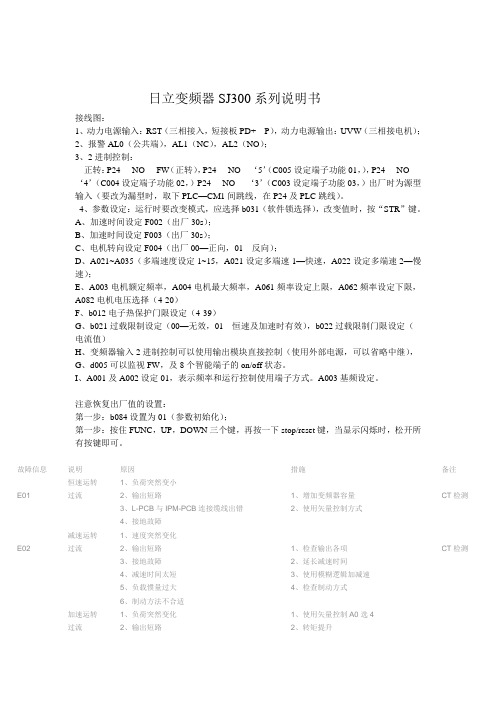
日立变频器SJ300系列说明书接线图:1、动力电源输入:RST(三相接入,短接板PD+---P),动力电源输出:UVW(三相接电机);2、报警AL0(公共端),AL1(NC),AL2(NO);3、2进制控制:正转:P24----NO----FW(正转),P24----NO----‘5’(C005设定端子功能01,),P24----NO----‘4’(C004设定端子功能02,)P24----NO----‘3’(C003设定端子功能03,)出厂时为源型输入(要改为漏型时,取下PLC—CM1间跳线,在P24及PLC跳线)。
4、参数设定:运行时要改变模式,应选择b031(软件锁选择),改变值时,按“STR”键。
A、加速时间设定F002(出厂30s);B、加速时间设定F003(出厂30s);C、电机转向设定F004(出厂00—正向,01---反向);D、A021~A035(多端速度设定1~15,A021设定多端速1—快速,A022设定多端速2—慢速);E、A003电机额定频率,A004电机最大频率,A061频率设定上限,A062频率设定下限,A082电机电压选择(4-20)F、b012电子热保护门限设定(4-39)G、b021过载限制设定(00—无效,01---恒速及加速时有效),b022过载限制门限设定(电流值)H、变频器输入2进制控制可以使用输出模块直接控制(使用外部电源,可以省略中继),G、d005可以监视FW,及8个智能端子的on/off状态。
I、A001及A002设定01,表示频率和运行控制使用端子方式。
A003基频设定。
注意恢复出厂值的设置:第一步:b084设置为01(参数初始化);第一步:按住FUNC,UP,DOWN三个键,再按一下stop/reset键,当显示闪烁时,松开所有按键即可。
故障信息说明原因措施备注恒速运转1、负荷突然变小E01 过流2、输出短路1、增加变频器容量CT检测3、L-PCB与IPM-PCB连接缆线出错2、使用矢量控制方式4、接地故障减速运转1、速度突然变化E02 过流2、输出短路1、检查输出各项CT检测3、接地故障2、延长减速时间4、减速时间太短3、使用模糊逻辑加减速5、负载惯量过大4、检查制动方式6、制动方法不合适加速运转1、负荷突然变化1、使用矢量控制A0选4过流2、输出短路2、转矩提升3、接地故障3、延长加速时间E03 4、启动频率调整太高4、增大变频器的容量CT检测5、转矩提升太高5、使用模糊逻辑加减速控制功能6、电机被卡住6、缩短变频器与电机之间距离7、加速时间过短8、变频器与电机之间连接电缆过长E04 停止时1、CT损坏CT检测过流2、功率模块损坏过载1、负荷太重1、减轻负荷E05 2、电子热继电器门限设置过小2、增大变频器的容量3、增大电子热继电器门限值制动电阻1、再生制动时间过长1、减速时间延长E06 过载保护2、L-PCB与IPM-PCB连接缆线出错2、增大变频器的容量3、A38设定为004、提高制动使用率1、速度突然减小1、延长减速时间2、负荷突然脱落2、增大变频器的容量E07 过压3、接地故障3、外加制动单元4、减速时间太短5、负荷惯性过大6、制动方法有问题1、周围噪声过大1、移去噪声源2、机体周围环境温度过高2、机体周围应便于散热、空气E08 EEPROM 3、L-PCB损坏流动良好故障4、L-PCB与IPM—PCB连接线松动3、更换制冷风扇或损坏4、更换相应元气件5、变频器制冷风扇损坏5、重新设顶一遍参数1、电源电压过低1、改变供电电源质量2、接触器或空开触点不良2、更换接触器或空开E09 欠压3、10分钟内瞬间掉电次数过多3、将F11设为380V4、启动频率调整太高4、将主线各节点接牢5、F11选择过高5、增加变压器容量6、电源主线端子松动7、同一电源系统有大的负载启动8、电源变压器容量不够1、CT损坏更换E10 CT出错2、CT与IPM—PCB上J51连线松了3、逻辑控制板上OP1损坏大部分问题是OP1损坏4、可能84与RS、DM、ZNR损坏1、周围噪声过大1、重新设置参数E11 CPU出错2、误操作2、移去噪声源3、CPU损坏3、更换CPUE12 外部跳闸1、外部控制线路有故障1、检测外部控制线路1、当选择此功能时,一旦INV处于1、变频器停止运行操作时E13 USP出错运行状态时,突然来电会发生此应该将运行开关关闭后再故障信息拉掉电源、不能直接拉电1、周围环境过于潮湿,电缆绝缘1、断开INV的输出端子,用摇性下降或电机绝缘性下降表检查电机的绝缘性,2、变频器输出接地不好2、换线缆,或烘干电机3、电机接地不好3、更换其它零部件E14 INV输出4、加、减速时间过短4、有时IPM-PCB是好的,但接地故障5、CT故障、L-PCB故障DM损坏6、IPM损坏7、L-PCB与IPM—PCB连接线松动、或损坏8、如果使用电控柜,可能输出输入电缆磨损与电控柜连接一体带电9、变频器输出电缆断线10、输出端子松动11、电机线圈断线12、电机功率太小13、由于噪声引起的误动作1、电源电压过高1、能否降低电源电压E15 电源电压2、F11设置过低2、根据实际情况选择F11值过高3、AVR功能没有起作用3、输入侧安装AC电抗器E16 瞬间电源1、电源电压过低故障2、接触器或空开触点不良E17~E20 选件板故障E21 变频器内部1、制冷风扇不转/变频器内部温度过高SJ300 温度过高2、散热片堵塞SJ200 E23 CPU与闸阵列连接复杂SJ300故障1、三相电源缺相1、检查供电电源E24 缺相保护2、接触器或空开触点不良2、更换接触器或空开3、L-PCB与IPM-PCB连线不良3、换一块L-PCB仍旧不好、再4、IPM与DM连线换连线仍旧不好,则IPM—(仅限30KW以上)PCB损坏E30 IGBT故障1、暂态过流(SJ300无E31、E32、E33等)1、负荷突然改变2、变频机体温升过高3、周围环境过于潮湿,电缆绝缘E31、E32、E33、E34主要是E31 恒速过流性下降或电机绝缘性下降输出侧的原因4、变频器输出接地不好解决办法使用模糊控制5、电机接地不好即A59:26、IPM损坏1、减速时间设置不当2、速度突然变化E32 减速过流3、输出短路4、接地故障5、IPM损坏1、速度突然增加2、负荷突然变化3、输出短路E33 加速过流4、接地故障5、启动频率调整太高6、转矩提升太高7、电机被卡住8、IPM损坏9、载波频率过高10、IPM-PCB损坏(仅限J300-750HFE4以上型号)11、PM与底座的散热硅胶涂抹的不均匀1、变频器震动过大2、IPM损坏E34 停止时3、变频器没有垂直安装过流4、环境温度过高5、内部电源损坏6、制冷风扇不转E35 电机过热热敏电阻与变频器智能端子连接后如果电机温度过高,变频器跳闸E60 通信故障通信网络看门狗超时1、复位信号被保持1、按下(1键或2键)键即能恢复ˉˉˉˉ上面四横杠2、面板和变频器之间出现错误2、再一次接通电源————中间四横杠1、关断电源时显示__U 1、输入电压不足时____下面四横杠无任何跳闸历史时显示————闪烁1、逻辑控制板损坏2、开关电源损。
东方日立变频器操作规程

DHVECTOL系列高压大功率变频器操作规程赵松变频器控制柜内开关说明:一、安全信息,请先阅读对于任何设备,正常的操作和使用以及必要的维护是保证其安全运行的一个十分重要的环节,变频器的运行及维护人员必须详细了解和严格遵守“本注意事项”中的相关内容。
厂家应根据自身工艺要求,结合本“操作注意事项”制定出相应的操作规程,以确保变频器的安全稳定运行。
1.1变频器操作注意事项1.1.1变频器为高压危险装置,任何操作人员必须严格遵守操作规程;1.1.2严禁无关人员任意指点触摸屏,以防产生误操作,影响生产;1.1.3使用触摸屏时,只需用手指轻触即可,严禁使劲敲击或用硬物点击;1.1.4变频器运行时不要随便打开柜门,否则有安全隐患,系统将进行声音报警;1.1.5变频器出现轻故障时,虽然不会立即停机,但必须及时处理,否则会演变成重故障,导致停机;1.1.6严格保证变频器运行的环境温度不超过40℃,否则变频器的寿命及运行可靠不能保证;1.1.7变频器所有参数在设备交付运行前都已进行合理设置,用户不得随意更改。
如果确需更改,请经东方日立(成都)电控设备有限公司用户服务中心人员许可后方可更改,否则将会产生严重后果。
1.1.8严禁随意按下“紧急停机”按钮。
1.1.9严禁在运行过程中对变频器做复位动作。
1.2.0严禁在运行过程中对变频器修改参数。
1.2变频器启动注意事项1.2.1高压合闸后,确定变频器冷却风机运行正常;1.2.2变频器6kV电源开关的合闸必须由变频器自身信号发出,严禁人为合变频器输入输出的6kV高压开关。
操作时只需要将高压开关推至工作位置即可;1.2.3如果变频器始终没有提供“高压合闸允许”信号,请确认变频器是否有故障信号,变频器本身是否处于故障状态;变频器就绪条件:控制电源开关QF1(220V电源)是否在合的位置,紧急跳闸是否按下,主板重故障(PLC的输入点I0.1不亮),主板轻故障(PLC的输入点I0.5不亮)。
日立变频器操作说明SJ完整版

日立变频器操作说明S JHEN system office room 【HEN16H-HENS2AHENS8Q8-HENH1688】SJ300型日立变频器操作说明该变频器采用“标准数字操作器OPE--S”,内部参数我厂已经设定,出厂时设定为“就地”操作,但只需简单调试就能实现“就地/集控”的操作转换。
一.就地操作按“功能键”显示“d001”,按“向下键”直至显示“A- - -”, 按“功能键”显示“A001”,再按“功能键”显示“01”,按“向上键”显示“02”频率由操作器设定,按“存储键”确认。
按“向上键”显示“A002”,按“功能键”显示“01”,再按“向上键”显示“02”运行指令由操作器控制,按“存储键”运行键指示灯亮。
输出频率由F001设定,出厂时设定为50Hz。
按“功能键”显示“A- - -”, 按“向上键”直至显示“d001”输出频率监视,再按“功能键”显示“”即为输出频率,“就地操作”设定完毕。
按“运行键”电动机运行,按“停止/重置键”电动机停止。
二.集控操作按“功能键”显示“d001”,按“向下键”直至显示“A- - -”, 按“功能键”显示“A001”,再按“功能键”显示“02”,按“向下键”显示“01”频率设定由控制端子操作,按“存储键”存储参数。
按“向上键”显示“A002”,按“功能键”显示“02”,再按“向下键”显示“01”运行指令由控制端子操作,按“存储键”确认。
4-20mA控制频率时设定:A101=0、A102=50、A103=20、A104=100。
按“功能键”显示“A- - -”, 按“向上键”直至显示“d001”输出频率监视,再按“功能键”显示“”即为输出频率,现在“频率”的高低由DCS系统4-20mA信号控制,“集控操作”设定完毕。
合上Q3(控制柜内C45单极空气开关)变频器即为“集控”运行,这时电动机的“起动/停止”及“转速”均由DCS系统控制。
*说明:电机正反转以集控为准,就地控制的转向可通过F004设定,“00”为正转;“01”为反转。
日立变频空调操作手册说明书
IOD-40249/2016OPERATION MANUALMODELSAir Handling UnitFXTQ09TAVJUA FXTQ09TAVJUD FXTQ12TAVJUA FXTQ12TAVJUD FXTQ18TAVJUA FXTQ18TAVJUD FXTQ24TAVJUA FXTQ24TAVJUD FXTQ30TAVJUA FXTQ30TAVJUD FXTQ36TAVJUA FXTQ36TAVJUD FXTQ42TAVJUA FXTQ42TAVJUD FXTQ48TAVJUA FXTQ48TAVJUD FXTQ54TAVJUA FXTQ54TAVJUD FXTQ60TAVJUAFXTQ60TAVJUDSYSTEM Inverter Air ConditionersRead these instructions carefully before installation. Keep this manual in a handy place for future reference. This manual should be left with the equipment owner.Lire soigneusement ces instructions avant l’installation.Conserver ce manuel à portée de main pour référence ultérieure. Ce manuel doit être donnéau propriétaire de l’équipement.Lea cuidadosamente estas instrucciones antes de instalar.Guarde este manual en un lugar a mano para leer en caso de tener alguna duda. Este manual debe permanecer con el propietario del equipo.•Do not allow children to play on or around the unit to prevent injury.•The heat exchanger fins are sharp enough to cut. To avoid injury, wear gloves or cover the fins while work-ing around them.•Do not put a finger or other objects into the air inlet or air outlet. The fan is rotating at high speed and will cause injury.•Check the unit foundation for damage on a continu-ous basis, especially if it has been in use for a long time. If left in a damaged condition the unit may cause injury.•Placing a flower vase or other containers with water or other liquids on the unit could cause a shock or fire if a spill occurs.•Never touch the internal parts of the controller. Do not remove the front panel because some parts in-side are dangerous to touch. To check and adjustinternal parts, contact your dealer.•Do not use the heat pump for any other purposes other than comfort cooling or heating. Do not use the unit for cooling precision instruments, food, plants, animals or works of art.•Do not place items under the indoor unit as they may be damaged by condensates that may form if the humidity is above 80% or if the drain outlet gets blocked.•Before cleaning, stop the operation of the unit by turning the power off or by pulling the supply cord out from its receptacle. Otherwise, an electric shock and injury may result.•Do not wash the heat pump with excessive water. An electric shock or fire may result.•Avoid placing the controller in a spot splashed with water. Water entering the controller may cause an electric shock or damage the internal electronic parts.•Do not operate the heat pump when using a room fumigation type of insecticide. Failure to observe this could cause the chemicals to be deposited in the unit and can endanger the health of those who are hyper-sensitive to chemicals.•The appliance is not intended for use by young chil-dren or infirm persons without supervision.•The remote controller should be kept away from chil-dren so they cannot play with it.•Consult with the installation contractor for cleaning.•Incorrect cleaning of the inside of the heat pump could make the plastic parts break and cause water leakage or electric shock.•Do not touch the air inlet or aluminum fin of the heat pump as they can cut and cause injury.•Do not place objects in direct proximity of the out-side unit. Do not let leaves and other debris accumu-late around the unit. Leaves are a hotbed for small animals which can enter the unit. Once inside the unit, animals can cause the unit to malfunction and cause smoke or fire when they make contact withelectrical parts.•Never press the button of the remote controller with a hard, pointed object. The remote controller may be damaged.•Never pull or twist the electric wire of the remote con-troller. It may cause the unit to malfunction.•Do not place appliances that produce open flames in places that are exposed to the air flow of the unit or under the indoor unit. It may cause incomplete com-bustion or deformation of the unit due to the heat.•Do not expose the controller to direct sunlight. The LCD display can become discolored and may fail to display the data.•Do not wipe the controller operation panel with ben-zene, thinner, chemical dust cloth, etc. The panel may get discolored or the coating can peel off. If it is heavily dirty, soak a cloth in water-diluted neutral detergent, squeeze it well and wipe the panel clean.Then wipe it with another dry cloth.•Dismantling of the unit, disposal of the refrigerant, oil, and additional parts, should be done in accor-dance with the relevant local, state, and national regu-lations.•Operate the heat pump in a sufficiently ventilated area and not surrounded by obstacles. Do not use the heat pump in the following places.a.Places with a mist of mineral oil, such as cuttingoil.b.Locations such as coastal areas where there is alot of salt in the air.c.Locations such as hot springs where there is a lotof sulfur in the air.d.Locations such as factories where the power volt-age varies a lot.e.In cars, boats, and other vehicles.f.Locations such as kitchens where oil may splat-ter or where there is steam in the air.g.Locations where equipment produces electromag-netic waves.h.Places with an acid or alkaline mist.i.Places where fallen leaves can accumulate orwhere weeds can grow.•Do not attempt to do electrical work or grounding work, unless you are licensed to do so. Consult with your dealer for electrical work and grounding work.•Pay attention to operating sound. Be sure to use the following places:a.Places that can sufficiently withstand the weightof the heat pump yet can suppress the operat-ing sound and vibration of the heat pump.b.Places where warm air from the air outlet of theoutside unit or the operating sound of the out-side unit does not annoy neighbors.•Consult your dealer if the heat pump in operation gen-erates unusual noise.•Make sure that the drainpipe is installed properly to drain water. If no water is discharged from the drain-pipe while the heat pump is in the cooling mode, the drainpipe may be clogged with dust or dirt and water leakage from the indoor unit may occur. Stop oper-ating the heat pump and contact your dealer.2.3.MAINTENANCE•Only a qualified person is allowed to perform mainte-nance without daily maintenance.•Before touching any of the connection wirings, be sure to turn off all power supply switches.•For installation of optional parts, only a qualifited person is allowed to do so.Be sure to use optional parts specified by the manufac-turer. Installation in your own manner may result in wa-ter leakage, electric shock or fire.•Do not use flammable material (e.g. hair-spray or insec-ticide) near the product.•Only proceed with the unit cleaning after stopping the operation and turning the power supply off.Failure to do so may result in electric shocks or injury.•Do not wash the heat pump or air handler with water.Failure to do so may result in an electric shock.•Consult with installation contractor for cleaning the inside of the air handler.Wrong cleaning procedures may break plastic parts or cause water leakage or electric shock.•Use a stable prep stand.Pay extra attention when cleaning the air handler. (Maintenance and inspection)•Clean the drain pan periodically. The drain pipes clogged with dust will cause water leakage.•For cleaning, consult with your Daikin dealer. (Before each season when cooling or heating is required, clean the air handler.)•If the area around the indoor unit is very dusty, use a dust proof cover (local procurement).(Cleaning the inside of the indoor unit)•It is necessary to clean the inside of the indoor unit peri-odically.Since the cleaning requires special technologies, requesta Daikin dealer to clean them.(Electric heater replacement interval)•The electric heater should be replaced every ten years.This replacement interval is a guideline for ensuring safe and trouble-free operation of the product for many years. (Cleaning the air filter)•The air filter is an optional accessory.EXPLANATION:•Removing the air filter except when cleaning the air han-dler may result in accidents.•Replace the filter when one of the following messages displayed on the bottom of remote controller screen.- Time to clean filter & element- Time to clean filter•If using the air handler under very dusty environment, increase the frequency of air filter cleaning.•Reset the filter sign on main menu of remote controller.Refer an operation manual of remote controller for de-tail.•Consult dealer to change filter setting time to display fil-ter change alarm on remote controller screen. (The de-fault factory setting is 2500 hours.)•There are the following time, display pattern: 1250, 2500, 5000, 10000.•Do not allow the indoor unit to get wet as it may cause an electric shock or fire._______________________________________________ 4. PRECAUTIONSIf the following phenomenon occurs, contact your dealer.•Any abnormalities in the operation of the heat pump or air handler such as smoke or fire could result in severe injury or death.Turn off the power and contact your dealer immediately for instructions._______________________________________________ Phenomenon•The unit may operate with the airflow rate at high speed even though the airflow rate was set to low speed using the remote controller during ELECTRIC HEATER opera-tion.Take the following actions before contact.Check to see if an optional electric heater is installed.The unit operates with the airflow rate at high speed dur-ing ELECTRIC HEATER operation regardless of the re-mote controller airflow rate setting or display.Phenomenon•The safety devices such as fuse, breaker, ground fault interrupter, etc. often operate or operations of the opera-tion switch are unstable.Take the following actions before contact.Turn off the switch.•If the ON/OFF switch does not properly work, Take the following actions before contact.Turn off the main power switch.Phenomenon•Water leaks out from the air handle r.Take the following actions before contact.Stop the operation.Phenomenon•Error message is displayed. See the remote controller operation manual for details.Inform the dealer of the details being displayed on the remote controller.。
- 1、下载文档前请自行甄别文档内容的完整性,平台不提供额外的编辑、内容补充、找答案等附加服务。
- 2、"仅部分预览"的文档,不可在线预览部分如存在完整性等问题,可反馈申请退款(可完整预览的文档不适用该条件!)。
- 3、如文档侵犯您的权益,请联系客服反馈,我们会尽快为您处理(人工客服工作时间:9:00-18:30)。
SJ300型日立变频器操作说明该变频器采用“标准数字操作器OPE--S”,内部参数我厂已经设定,出厂时设定为“就地”操作,但只需简单调试就能实现“就地/集控”的操作转换。
一.就地操作
按“功能键”显示“d001”,按“向下键”直至显示“A- - -”, 按“功能键”显示“A001”,再按“功能键”显示“01”,按“向上键”显示“02”频率由操作器设定,按“存储键”确认。
按“向上键”显示“A002”,按“功能键”显示“01”,再按“向上键”显示“02”运行指令由操作器控制,按“存储键”运行键指示灯亮。
输出频率由F001设定,出厂时设定为50Hz。
按“功能键”显示“A- - -”, 按“向上键”直至显示“d001”输出频率监视,再按“功能键”显示“”即为输出频率,“就地操作”设定完毕。
按“运行键”电动机运行,按“停止/重置键”电动机停止。
二.集控操作
按“功能键”显示“d001”,按“向下键”直至显示“A- - -”, 按“功能键”显示“A001”,再按“功能键”显示“02”,按“向下键”显示“01”频率设定由控制端子操作,按“存储键”存储参数。
按“向上键”显示“A002”,按“功能键”显示“02”,再按“向下键”显示“01”运行指令由控制端子操作,按“存储键”确认。
4-20mA控制频率时设定:A101=0、A102=50、A103=20、A104=100。
按“功能键”显示“A- - -”, 按“向上键”直至显示“d001”输出频率监视,
再按“功能键”显示“”即为输出频率,现在“频率”的高低由DCS系统4-20mA 信号控制,“集控操作”设定完毕。
合上Q3(控制柜内C45单极空气开关)变频器即为“集控”运行,这时电动机的“起动/停止”及“转速”均由DCS系统控制。
*说明:电机正反转以集控为准,就地控制的转向可通过F004设定,“00”为正转;“01”为反转。
采用默认值时为正转。
靖江市合金钢机械厂
2004年5月8日。