04 TP12701 technical presentation
Okuma THINC Startup Service Installation and User
Okuma America Corporation Okuma THINC Startup ServiceInstallation and User ManualDocument No. S5085-130-04Product Version: 5.2.0.0Revision HistoryDate Version Description Author 2017-05-26 S5085-130-00 Product Version 4.4.0.0 Casey M. Croussore 2018-06-04 S5085-130-01 Product Version 4.6.0.0 Casey M. Croussore 2022-01-22 S5085-130-02 Product Version 5.0.0.1; 5.0.0.2 Casey M. Croussore 2022-03-12 S5085-130-04 Product Version 5.2.0.0 Casey M. CroussoreTable of Contents1.Introduction 42.Definitions 43.Version Information E rror! Bookmark not defined.4.Installation 45.Operation 86.Event and Error Logging 207.Settings 208.Uninstallation 201. IntroductionThe purpose of the Okuma THINC Startup Service (hereafter TSS) is to launch customer applicationswhen, and only when, the Okuma OSP System (NC Control) software has fully booted and the OkumaTHINC API is available.Applications which rely on the THINC API should be registered with the TSS to be launched by it, rather than performing independent checks to determine THINC API status.2. Definitions2.1.1Startup Item: Any Application, Windows Service, or file which is registered with the THINC Startup Service to be run when the control starts.2.1.2TSS: THINC Startup Service3. Version Information•As of this time, v5.0.0.1 is the latest version that will support Windows XP•Version 5.2.0.0 supersedes v5.0.0.2 in the US market, and supports only:o THINC API v1.19.0.0 and highero Windows 7o Windows 10•At a later date, a single unified version, supporting Windows XP, Windows 7 and Windows 10 will be releasedNote: Windows XP is also supported in versions 4.4 and 4.6.4. Installation4.1 Installation Prerequisites4.1.1Software which is installed during installation of the TSS•THINC API v1.19.0.0 or higher•Microsoft .NET Framework v4.0 (full)•Windows 7 or Windows 10 (Windows XP is not supported in this release)4.2 Product Installation4.2.1Installation of Prerequisite Software4.2.1.1“Windows Only Mode”: It is not necessary to install the TSS in Windows Only Mode. However,if installation is done with the OSP System software running, a shortcut to the “Startup Settings” will not appear on the Vertical Function Key Menu until the control is re-started.4.2.1.2Locate “Setup_Okuma THINC Startup Service*.exe”4.2.1.3Double-click “Setup_Okuma THINC Startup Service*.exe” to begin installation.4.2.1.4The following will be displayed. Click “Next” to proceed.4.2.1.5Confirm the installation path and confirm installation:displayed. Click “Close” to exit the installer.5. Operation5.1 Launching the TSSThe TSS runs automatically when the machine starts. It will launch any Startup Items under its control without user intervention.To access the user interface and settings, locate the shortcut on the Vertical Function Key menu:5.2 Startup Item SettingsThere are several settings which can be applied to any Startup Item:NAME User-defined identifier for the Startup Item. NAME must be unique.If it is not, the TSS will assign a unique name. Example: If “Notepad” is added morethan one time, the new entries will be incremented: “Notepad_(1)”; “Notepad_(2)”; etc. PATH Full path to the file or executable file to be launched.This setting is not used if the Startup Item is a Service.ARGUMENTS Command line arguments to be applied when the Startup Item is launched. DELAY When all other startup conditions are met, the DELAY represents the numberof additional milliseconds that the TSS will wait before starting the Item. SEQUENCE Process name which must exist before the Startup Item will be launched.USER NAME User name under which to run the Process, file or ServicePASSWORD Password associated with the USER NAMELAUNCH TYPE Choose from “ONCE” or “MONITOR”ONCE: The Startup Item is launched one time when the machine is started.If the user closes the file or process, the TSS does not attempt to re-launch it.MONITOR: The Startup Item is launched when the machine is started.If the user closes it, the TSS will attempt to re-launch it.TYPE Indicates whether the Startup Item is a Windows Process or a Windows Service WAIT FOR API If checked the Startup Item will not be launched until the THINC API is available.If un-checked, the Startup Item will be launched immediately after the TSS itself starts. ENABLED Indicates whether the Startup Item being edited is enabled or disabled.Require Machine Restart After Settings Saved The user will not be prompted to re-start the Startup Item after saving settings. The Startup Item will only re-start when the machine isre-started.Identification Indicator: This shows the ID of the Startup Item. This value cannot be changed by the user, and is only used in the internal functions of the TSS:5.3 Startup Items’ StatusBelow is a description of each Status that may be seen on the Status line of the TSS, reflecting the actual Status of the selected Startup Item.COMPLETE All startup actions are completeDELAY_DONE Item has completed any DELAY waitDELETING Item is in the process of being deletedDISABLED Item is disabled; will not start at machine startFAILED Item has encountered a critical errorLOCK_WAITING_SERVICE Item is waiting for its Service to start or stopMONITORING Item has started, and is monitoring its processREADY Item has not yet started, but is enabledRESTART_REQUESTED Restart of Item is pendingSTARTING Item is starting, but has not entered any waiting period yet STOPPED Item is stopped forciblySTOPPING Item is stopping due to user requestWAITING_API_DONE Waiting for THINC API availability is finishedWAITING_API_OK Item is waiting for THINC API availabilityWAITING_DELAY Item is waiting its specified DELAY valueWAITING_SEQUENCE Item is waiting for its SEQUENCE process to startWAITING_SEQUENCE_DONE Item has completed waiting for its SEQUENCE process (if any) to start 5.4 Adding a Startup Item5.4.1Click the Add Item button (Alternatively, the user can ‘drag and drop’ the executable or other file to themain form and the new Startup Item’s information will be populated).5.4.2The following dialog is displayed. Choose the Startup Item type from “Process (or file)” or “Service. “If using “Process (or file)”, any process (.exe) or file on the computer can be chosen. Choosing “Service” will allow the user to select a Windows Service.5.5 Adding a Process or File5.5.1Choose “Process (or File)”5.5.2Browse to the file (executable process or other) that is to be started.5.5.3Once selected, the settings for the new Startup Item will be displayed5.5.4When editing is finished, click the Save button. The new Startup Item is not added to the Startup Item List until it is saved.5.5.5If the Startup Item is Enabled, the user will see the following question:Click ‘Yes’ to start the Item immediately, or ‘No’ to wait until the next time the machine is started.5.5.6To cancel edits, click the Cancel buttonNote: After changes are saved, they cannot be cancelled using this button.5.6 Adding a Service5.6.1Select Service5.6.2 A list of Windows Services will be displayed.Note: Only Services which are set to start manually will be displayed.5.6.3The Settings for the Service will be displayed.5.6.4Once editing is complete, click the Save button, and the Service will be added to the Startup Item list.5.7 Editing a Startup Item5.7.1Click the Item to be edited in the list on the left, and its information will be displayed on the main form.5.7.2Make any desired changes. Below, as an example, the NAME is changed, and the Item is set to Disabled.5.7.3Use the Cancel button to undo changes, or save the Item5.8 Deleting a Startup Item5.8.1Click the Startup Item to be deleted in the list on the left5.8.2Click the Delete button5.9 Stopping a Startup Item5.9.1Click the Stop button and the currently-selected Startup Item will stop, but will not be Disabled.5.10 Minimizing the TSS to the System Tray5.10.1Click the Minimize button5.11 Closing the TSS5.11.1Click the Close button6. Event and Error LoggingEvents and errors are logged to a csv file in the \Logging directory under the Application’s installationdirectory. One log file is generated for each time the TSS starts. By default, the five most recent log files are retained; older log files are deleted.Important system events may be viewed on the System Events tab.Errors are also displayed to the user in a message box.A detailed Trace Log can be written for troubleshooting. To enable this, run the TSS main executable(THINCStartupProcess.exe) with a –trace command line switch:THINCStartupProcess.exe -trace7. SettingsApplication settings are stored in the installation directory in settings.xml. This file may be copied fromone machine to another, if desired. However, it should never be edited directly in a text editor, as any error in the XML can cause the Application to fail to start.8. UninstallationTo fully remove the TSS application, perform the following:Start the control in Windows Only mode.Navigate to Add and Remove Programs or Programs and Features (depending on your Windows version, and find “Okuma THINC Startup Service” in the list of installed programs.Double-click to uninstall.When the progress dialog closes, the THINC Startup Service will have been uninstalled from the targetmachine.。
DP1Users_Manual_cs

基本操作 曝光模式选择
37 37
自动模式 ...............................................................................37 P 程序式自动曝光 .....................................................................39 A 光圈先决自动曝光 .................................................................40 S 快门先决自动曝光 .................................................................41 M 手动控制曝光 ........................................................................42
• SD
记忆卡是不包含在标准包装配件内。阁下可自行选购所需品牌、 容量、型号 。
2
目
录
随机包装 / 配件内容 ......................................................................2 目 录 ..........................................................................................3 安全注意事项 ................................................................................6 相机保护及留意事项 ......................................................................9 相机各部件说明 .......................................................................... 11 彩色 LCD 显示屏提示 ..................................................................13 基本操作和快速参考 ....................................................................14
SCALANCE X201-3P IRT Managed IE IRT 交换机 6GK5201-3J

compact 90 mm 125 mm 124 mm 1 kg
Yes Yes Yes No
Product properties, functions, components / general
Cascading in the case of a redundant ring / at
50
reconfiguration time of <\~0.3\~s
Product extension / optional / C-PLUG
Yes
Further Information / Internet Links Internet-Link ● to website: Selector SIMATIC NET SELECTION TOOL ● to website: Industrial communication ● to website: Industry Mall ● to website: Information and Download Center ● to website: Image database ● to website: CAx Download Manager ● to website: Industry Online Support
● SICLOCK support
Yes
Protocol / is supported
● NTP
No
● SNTP
Yes
Standards, specifications, approvals Standard ● for FM
● for hazardous zone
● for safety / from CSA and UL ● for hazardous zone / from CSA and UL
PS2701普通光耦
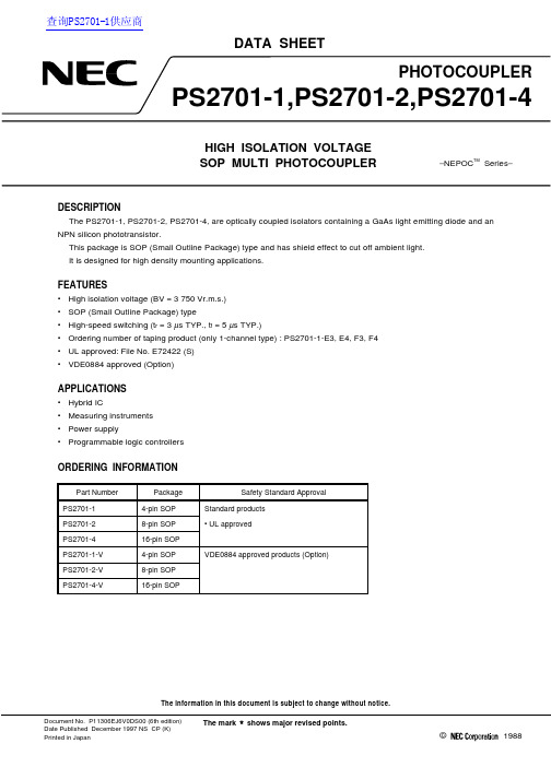
DATA SHEETThe information in this document is subject to change without notice.©1988Document No. P11306EJ6V0DS00 (6th edition)Date Published December 1997 NS CP (K)Printed in JapanPHOTOCOUPLERPS2701-1,PS2701-2,PS2701-4HIGH ISOLATION VOLTAGE SOP MULTI PHOTOCOUPLERThe mark shows major revised points.−NEPOC TMSeries −DESCRIPTIONThe PS2701-1, PS2701-2, PS2701-4, are optically coupled isolators containing a GaAs light emitting diode and an NPN silicon phototransistor.This package is SOP (Small Outline Package) type and has shield effect to cut off ambient light.It is designed for high density mounting applications.FEATURES•High isolation voltage (BV = 3 750 Vr.m.s.)•SOP (Small Outline Package) type•High-speed switching (t r = 3 µs TYP., t f = 5 µs TYP.)•Ordering number of taping product (only 1-channel type) : PS2701-1-E3, E4, F3, F4•UL approved: File No. E72422 (S)•VDE0884 approved (Option)APPLICATIONS•Hybrid IC•Measuring instruments •Power supply•Programmable logic controllersORDERING INFORMATIONPart Number Package Safety Standard ApprovalPS2701-14-pin SOP Standard products PS2701-28-pin SOP • UL approvedPS2701-416-pin SOP PS2701-1-V 4-pin SOP VDE0884 approved products (Option)PS2701-2-V 8-pin SOP PS2701-4-V16-pin SOP查询PS2701-1供应商2PACKAGE DIMENSIONS (in millimeters)PS2701-14.5 MAX.7.0±0.34.41.30.5±0.30.15+0.10–0.05TOP VIEW1. Anode2. Cathode3. Emitter4. Collector43122.00.1±0.12.3 M A X .2.54 1.2 MAX.0.4+0.10–0.050.25 MPS2701-29.3 MAX.2.00.1±0.12.3 M A X .2.541.2 MAX.0.4+0.10–0.050.25 MTOP VIEW123487651. 3. Anode2. 4. Cathode 5. 7. Emitter 6. 8. Collector7.0±0.34.41.30.5±0.30.15+0.10–0.05PS2701-419.46 MAX.TOP VIEW1. 3. 5. 7. Anode2. 4. 6. 8. Cathode 9. 11. 13. 15. Emitter 10. 12. 14. 16. Collector161514131211109123456782.00.1±0.12.3 M A X .2.541.2 MAX.0.4+0.10–0.050.25 M7.0±0.34.41.30.5±0.30.15+0.10–0.053ABSOLUTE MAXIMUM RATINGS (T A = 25 °C, unless otherwise specified)ParameterSymbolRatingsUnitPS2701-1PS2701-2,PS2701-4DiodeForward Current (DC)I F 50mA Reverse VoltageV R6V Power Dissipation Derating ∆P D /°C 0.8mW/°C Power Dissipation P D 80mW/ch Peak Forward Current*1I FP 1A TransistorCollector to Emitter Voltage V CEO 40V Emitter to Collector Voltage V ECO 6V Collector CurrentI C80mA/chPower Dissipation Derating ∆P C /°C 1.5 1.2mW/°C Power DissipationP C 150120mW/ch Isolation Voltage*2BV 3 750Vr.m.s.Operating Ambient Temperature T A –55 to +100°C Storage TemperatureT stg–55 to +150°C*1PW = 100 µs, Duty Cycle = 1 %*2AC voltage for 1 minute at T A = 25 °C, RH = 60 % between input and output4ELECTRICAL CHARACTERISTICS (T A = 25 °C)ParameterSymbol Conditions MIN.TYP.MAX.Unit DiodeForward Voltage V F I F = 5 mA 1.11.4VReverse Current I R V R = 5 V5µA Terminal CapacitanceC t V = 0 V, f = 1 MHz 30pFTransistor Collector to Emitter CurrentI CEO I F = 0 mA, V CE = 40 V 100nA CoupledCurrent Transfer Ratio *1CTR I F = 5 mA, V CE = 5 V 50100300%Collector Saturation VoltageV CE (sat)I F = 10 mA, I C = 2 mA 0.3V Isolation Resistance R I-O V I-O = 1 kV DC1011ΩIsolation Capacitance C I-O V = 0 V, f = 1 MHz0.4pFRise Time *2t r V CC = 5 V, I C = 2 mA, R L = 100 Ω3µsFall Time*2t f5*1CTR rank (only PS2701-1)P: 150 to 300 (%)L: 100 to 300 (%)M: 50 to 150 (%)*2Test circuit for switching timePW = 100 s,Duty cycle = 1/10µPulse inputV CCV OUTR L = 100 Ω50 ΩI F5TYPICAL CHARACTERISTICS (T A = 25 °C, unless otherwise specified)1005025075255075100Ambient Temperature T A (˚C)D i o d e P o w e r D i s s i p a t i o n P D (m W )DIODE POWER DISSIPATION vs.AMBIENT TEMPERATURE20015010050025*******Ambient Temperature T A (˚C)T r a n s i s t o r P o w e r D i s s i p a t i o n P C (m W )TRANSISTOR POWER DISSIPATION vs.AMBIENT TEMPERATUREPS2701-11.5 mW/˚CPS2701-2,PS2701-41.2 mW/˚C50200403010610248Collector to Emitter Voltage V CE (V)C o l l e c t o r C u r r e n t I C (m A )COLLECTOR CURRENT vs.COLLECTOR TO EMITTER VOLTAGEI F = 30 mA20 mA10 mA15 mA5 mA1000.110.01100.61.0 1.4 1.60.8 1.2Forward Voltage V F (V)F o r w a r d C u r r e n t I F (m A )FORWARD CURRENT vs.FORWARD VOLTAGE+25 ˚C 0 ˚C –25 ˚C –55 ˚CT A = +100 ˚C+75 ˚C +50 ˚C10 0000.11001 000101–6004080–40–202060100Ambient Temperature T A (˚C)COLLECTOR TO EMITTER DARKCURRENT vs. AMBIENT TEMPERATUREC o l l e c t o r t o E m i t t e rD a r k C u r r e n t I CE O (n A )V CE = 40 V24 V 10 V5050.1100.50.220210.20.6 1.00.00.40.8Collector Saturation Voltage V CE (sat) (V)C o l l e c t o r C u r r e n t I C (m A )COLLECTOR CURRENT vs.COLLECTOR SATURATION VOLTAGEI F = 25 mA10 mA 5 mA 2 mA 1 mA61.20.60.00.81.00.40.202550100–50–2575Ambient Temperature T A (˚C)NORMALIZED CURRENT TRANSFERRATIO vs. AMBIENT TEMPERATURENormalizedCurrentTransferRatioCTRNormalized to 1.0at T A = 25 ˚C,I F = 5 mA, V CE = 5 V300250150502001000.050.55500.1110Forward Current I F (mA)CurrentTransferRatioCTR(%)CURRENT TRANSFER RATIO vs.FORWARD CURRENTV CE = 5 V Load Resistance R L (Ω)SWITCHING TIME vs.LOAD RESISTANCESwitchingTimet(s)µV CC = 5 V,I C = 2 mA1000.50.150105150200 1 k 2 k100500Load Resistance R L (Ω)SWITCHING TIME vs.LOAD RESISTANCESwitchingTimet(s)µt ont offt dt s1.20.40.00.80.60.21.020500510200250100Frequency f (kHz)NormalizedGainGVFREQUENCY RESPONSER L = 1 kΩ510 Ω300 Ω100 Ω1.21.00.00.40.20.80.61021031104105106Time (Hr)LONG TERM CTR DEGRADATIONCTR(RelativeValue)I F = 1 mA, T A = 25 ˚CI F = 5 mA, T A = 25 ˚CI F = 20 mA, T A = 25 ˚CI F = 20 mA, T A = 60 ˚CI F = 5 mA, V CC = 5 V,CTR = 169 %1 0000.51005001015050.1100 1 k10 k50 k500 5 k100 kt ft st rt dRemark The measurement of TYPICAL CHARACTERISTICS are only for reference, not guaranteed.7TAPING SPECIFICATIONS (in millimeters)Outline and Dimensions (Tape)1.55±0.12.0±0.14.0±0.11.55±0.11.75±0.15.5±0.112.0±0.24.6±0.12.4±0.17.4±0.10.38.0±0.1Tape DirectionPS2701-1-E3PS2701-1-F3PS2701-1-E4PS2701-1-F4Outline and Dimensions (Reel)Packing: PS2701-1-E3, E4 900 pcs/reelPS2701-1-F3, F4 3 500 pcs/reel1.5±0.5120˚2.0±0.56.0±121.0±0.8φ60˚12.4+2.0–0.018.4 MAX.1.5±0.11.5±0.166φ13.0±0.5φP S 2701-1-E 3, E 4: 178P S 2701-1-F 3, F 4: 330φφ8RECOMMENDED SOLDERING CONDITIONS(1) Infrared reflow soldering •Peak reflow temperature235 °C (package surface temperature)•Time of temperature higher than 210 °C 30 seconds or less •Number of reflows Three•FluxRosin flux containing small amount of chlorine (The flux with a maximum chlorine content of 0.2 Wt % is recommended.)60 to 90 s (preheating)210 ˚C120 to 160 ˚CP a c k a g e S u r f a c e T e m p e r a t u r e T (˚C )Time (s)(heating)to 10 sto 30 s235 ˚C (peak temperature)Recommended Temperature Profile of Infrared ReflowPeak temperature 235 ˚C or belowCaution Please avoid to removed the residual flux by water after the first reflow processes.(2) Dip soldering •Temperature 260 °C or below (molten solder temperature)•Time10 seconds or less •Number of times One•FluxRosin flux containing small amount of chlorine (The flux with a maximum chlorine content of 0.2 Wt % is recommended.)9SPECIFICATION OF VDE MARKS LICENSE DOCUMENT (VDE0884)ParameterSymbolSpeckUnitApplication classification (DIN VDE 0109)for rated line voltages ≤ 300 Vr.m.s.IV for rated line voltages ≤ 600 Vr.m.s.III Climatic test class (DIN IEC 68 Teil 1/09.80)55/100/21Dielectric strengthMaximum operating isolation voltageU IORM 710V peak Test voltage (partial discharge test, procedure a for type test and random test)U pr850V peakU pr = 1.2 × U IORM , P d < 5 pCTest voltage (partial discharge test, procedure b for random test)U pr = 1.6 × U IORM , P d < 5 pC U pr1 140V peakHighest permissible overvoltage U TR 6 000V peakDegree of pollution (DIN VDE 0109)2Clearance distance > 5mm Creepage distance> 5mmComparative tracking index (DIN IEC 112/VDE 0303 part 1)CTI 175Material group (DIN VDE 0109)III a Storage temperature range T stg –55 to +150°C Operating temperature range T A –55 to +100°CIsolation resistance, minimum value V IO = 500 V dc at T A = 25 °CRis MIN.1012ΩV IO = 500 V dc at T A MAX. at least 100 °CRis MIN.1011ΩSafety maximum ratings(maximum permissible in case of fault, see thermal derating curve)Package temperatureTsi 150°C Current (input current I F , Psi = 0)Isi 200mA Power (output or total power dissipation)Psi300mWIsolation resistanceV IO = 500 V dc at T A = 175 °C (Tsi)Ris MIN.109Ω[MEMO] 10[MEMO]11CAUTIONWithin this device there exists GaAs (Gallium Arsenide) material which is aharmful substance if ingested. Please do not under any circumstances break thehermetic seal.NEPOC is a trademark of NEC Corporation.No part of this document may be copied or reproduced in any form or by any means without the prior written consent of NEC Corporation. NEC Corporation assumes no responsibility for any errors which may appear in this document.NEC Corporation does not assume any liability for infringement of patents, copyrights or other intellectual property rights of third parties by or arising from use of a device described herein or any other liability arising from use of such device. No license, either express, implied or otherwise, is granted under any patents, copyrights or other intellectual property rights of NEC Corporation or others.While NEC Corporation has been making continuous effort to enhance the reliability of its semiconductor devices, the possibility of defects cannot be eliminated entirely. To minimize risks of damage or injury to persons or property arising from a defect in an NEC semiconductor device, customers must incorporate sufficient safety measures in its design, such as redundancy, fire-containment, and anti-failure features.NEC devices are classified into the following three quality grades:"Standard", "Special", and "Specific". The Specific quality grade applies only to devices developed based on a customer designated "quality assurance program" for a specific application. The recommended applications of a device depend on its quality grade, as indicated below. Customers must check the quality grade of each device before using it in a particular application.Standard: Computers, office equipment, communications equipment, test and measurement equipment, audio and visual equipment, home electronic appliances, machine tools, personal electronicequipment and industrial robotsSpecial: Transportation equipment (automobiles, trains, ships, etc.), traffic control systems, anti-disaster systems, anti-crime systems, safety equipment and medical equipment (not specifically designedfor life support)Specific: Aircrafts, aerospace equipment, submersible repeaters, nuclear reactor control systems, life support systems or medical equipment for life support, etc.The quality grade of NEC devices is "Standard" unless otherwise specified in NEC's Data Sheets or Data Books. If customers intend to use NEC devices for applications other than those specified for Standard quality grade, they should contact an NEC sales representative in advance.Anti-radioactive design is not implemented in this product.M4 96. 5。
密封产品及材料手册 苏州优泰科

密封产品及材料手册SEALS AND SEALING MATERIALSPRODUCT CATALOGUE2011液压支架立柱缸液压支架护帮千斤顶订货所需尺寸为:ΦD..........outside diam. L..........groove heightΦd..........inside diam.H..........total wiper height外径内径沟槽高度防尘封总高度订货示例名称W01订货所需尺寸为:ΦD..........outside diam. L..........groove height Φd..........inside diam. H..........total wiper height外径内径沟槽高度防尘封总高度订货示例名称下列为标准沟槽尺寸Φd 6-49.9W05W02订货所需尺寸为:ΦD..........outside diam. L..........groove height Φd..........inside diam. H..........total wiper height外径内径沟槽高度防尘封总高度订货示例名称沟槽尺寸(d*D*L*H)下列为标准沟槽尺寸W03下列为标准沟槽尺寸ΦdW25下列为标准沟槽尺寸ΦdΦDW28下列为标准沟槽尺寸ΦdR1012活塞用密封沟槽Piston seals housing recommendations订货所需尺寸为:ΦD..........outside diam. L..........groove height Φd..........inside diam.外径内径沟槽高度P01,P02,P03,P04,P05,P06,P07,P20,P21主要应用适合于液压缸和气缸优点嵌入沟槽稳定,密封效果良好,温度范围广材料聚氨酯类,橡胶类订货所需尺寸为:ΦD..........outside diam. L..........groove heightΦd..........inside diam.外径内径沟槽高度P08主要应用标准液压缸以及行走液压机械优点摩擦力低,抗挤压,无爬行材料四氟乙烯类+丁腈橡胶或氟胶,超高硬度聚氨酯+丁腈橡胶不适合P08-DP下列为标准沟槽尺寸下列为标准沟槽尺寸下列为标准沟槽尺寸ΦDRT12<2525-45.946-124.9。
杜邦STOP-1 面谈技术
1.Reactions of People人员的反应●Can you stop for a minute and tell me about the job you’re doing?可不可以耽误你一分钟的时间?请告诉我你正在进行的工作是什么?●What personal protective equipment is required for the job? Is italways available? Is it in good condition? Have you received training in using this personal protective equipment?在你的工作上需要哪些个人防护装备?是不是每次都有个人防护装备供你使用?装备的状况良好吗?你是否接受过使用个人防护装备的训练?●What other position could you be in that would make this job safer? 你是否可以换到其它的工作位置,使得这项工作能进行得更安全?●How could you or someone else get hurt under these circumstances? 在这些状况下,你或其他人可能会如何地受到伤害?●What could happen if…?如果一旦……可能会发生什么事?●How can this job be done more safely?你如何能使这项工作更安全?2.Persona Protective Equipment个人防护设备●What are some potential safety risks on this job?在这个工作上有哪些安全上潜在的危险?●What are you wearing to protect yourself from possible hazards?你穿了哪些可以保护你不受潜在危险伤害的衣物?●What personal protective equipment is available to protect you fromthese hazards?公司备有哪些个人防护装备可以保护你不受到这些伤害?●What is the difference between the clothing you wear off the job (forexample, your own shoes) and the required personal protective equipment for this job (safely shoes)?在你不上工时穿着的衣物(例如自己的鞋子)和在上工时穿着的个人防护装备(如安全鞋)有何不同?●What some of the common causes are of injures on this type of job? 在这一类型的工作上有哪些常见原因会导致伤害?●How can you keep from injuring yourself on this job?如何能避免在工作上受到伤害?●What parts of your body do you think need protection against the risksinvolved in you job?你认为,要避免在工作上受到伤害,你身体的哪些部位需要采取防护措施?●What types of personal protective equipment are required for your job? 在你工作时,需要哪些种类的个人防护装备?●What training did you receive in the care and use of the personalprotective equipment required for your job?关于你工作上规定的个人防护装备,你曾接受哪些维护与使用上的训练?●Is the required personal protective equipment correct for the job? 规定的个人防护装备是否适用于你的工作?●How do you know the personal protective equipment is in good condition? 你如何知道个人防护装备处于良好的状况?●Is the personal protective equipment used properly? What training isrequired?个人防护装备使用的方法是否正确?需要哪些训练?●Does the personal protective equipment fit properly? How often do youfit-test?个人防护装备是否合身?你多久会试穿一次?●How do you feel about wearing personal protective equipment now thatwe’ve talked?关于我们现在讨论的个人防护装备,你对于它的穿戴有何看法?●What other jobs do you do that require personal protective equipment? 你还有哪些工作需要穿着个人防护装备?3.Position of people人员的位置●What are the most serious potential injury causes in your area ofresponsibility?在你的责任区中,有哪些最严重的潜在伤害原因?●What ergonomic risk factors exist in your area?在你的责任区中,有哪些人体工学方面的危险?●What changes have been made in your area to reduce the risk ofcumulative trauma disorders?在你的责任区里,曾采取哪些修正措施以减少累积伤害症状的奉献?●What do you need to remember about talking with people?在与人交谈时,你应该记住哪些事项?●What should you do when you observe a person in a position that cancause an injury? (Talk with the person until he or she understands why the unsafe act is hazardous; listen; giving the person a chance to tell you what the hazards are.)当你观察到某人的姿势可能导致伤害时,你应该采取什么行动?(与该员工交谈,知道他或她了解为什么不安全的行为有危险为止;聆听,让他或她有机会告诉你有哪些危险)●What are the best ways to prevent the unsafe acts that cause injuriesin you area?要避免在你的责任区中发生会导致伤害的不安全行为,最好的办法是什么?●Could anything unexpected happen that might injure you or someone else?What?是否有意外的事发生,可能导致你或他人受伤?例如什么事?●What motions do you repeat over and over in your job?你在工作上有哪些会一直使用重复的动作?●How could you do this job more safely?如何能使工作更安全?●How often do you stand or sit in one position for a long time?你保持相同的坐姿或站姿多久?●What other position could you be in to do your job?你在工作时还可能有哪些姿势?●What is potentially unsafe about the position you are in?你的姿势有哪些潜在的危险?●What equipment could you use to make your job safer? Is it available?Do you know how to use it?你可以用哪些设备来使工作更安全?公司是否有提供这种设备?你是否知道如何使用这种设备?●How might someone else have been injured as a result of the positionyou were in?你的姿势如何可能导致他人受伤?●How often must you do your work in places that are awkward, hazardous,elevated, and congested and so on?你是否常在不自然、危险、高处、拥挤等等地方工作?●What can you do to protect yourself and others from injury under theseconditions?在这些状况下,你如何保护自己与他人不至受伤?4.Tools and Equipment工具和设备●How could using these tools or this equipment have the potential tobe hazardous?使用这些工具或这种设备为什么会导致危险?●How often do you use this piece of equipment?你多常使用这种设备?●Is the equipment right for the job? Is it in safe condition? Are youusing it correctly?这种设备是否适合这项工作?它是否处于良好的状况?你的使用方法是否正确?●What do you check before you use this equipment?你在使用这种设备前是否会检查它?●What equipment would enable you to perform this job more safely? Isit available? Do you know how to use it?哪一种设备可以使安全执行这项工作?是否有提供这种设备?你是否知道如何使用这种设备?●When you are doing a job, do you check above you to be sure there isnothing that could cause harm to you or others?当你在做一件工作使,你是否会检查你的头顶,以确定没有东西会伤害到你或其他人?●What precautions could you take to protect people below you?你可以采取什么措施来保护位于你下方的人?●Is there anything inside this equipment or place that unexpectedlyhurt you or others?这种设备里面是否有什么东西可能会突然地伤害到你或他人?●Could anything behind you unexpectedly injure you?你的后方是否有东西可能突然地伤害到你?●Do you listen for unusual sounds? Do you smell for unfamiliar orunusual odors?你是否会听听看有没有不寻常的声响?你是否会闻闻是否有不熟悉或不寻常的气味?●Did you touch something that was unusually hot, cold, or wet?你是否有碰到特别冷、热、或湿的东西?●Do people in my area see the same problem I see?你责任区里的员工是否有看到我所观察到的问题?●Do they reinforce safe work practices among one another?他们是否彼此相互加强安全作业事务?5.Procedures and Orderliness程序和整理●What serious unsafe act could be committed in your area because ofinadequate procedures?在你的责任区中,因为不适合的程序可能会造成什么样的不安全行为?●What skills can you use to determine whether procedures are adequate,known and understood, and follower?Decide to pay attention to how employees are following procedures. Stop near enough to observe them as they do the job paying special attention to job and safety procedures. Act to talk with them about procedures, especially with regard to whether they are known and understood. Report using a Safety Observation Card.你可以使用哪些技巧来确认作业程序是否适合,且被员工知道、了解并遵守?决定——要注意员工如何遵守程序。
Technical Guide

Plastics piping systems for hot and cold water under pressureConstitution of the Technical Application Documentsor Technical Assessment request filesThis document cancels and replaces the previous Guide, published in the CSTB Books no. 257-2 of March 1985.e-Cahiers of CSTB 3597CHAPTER 1 – PURPOSE OF THE GUIDE AND FIELD OF APPLICATION 1.1 PurposeThe purpose of this Guide is to define the elements that will be useful when examining requests for Technical Assessments or for Technical Application Documents concerning “Piping Systems” composed of synthetic material based tubes and fittings of metal or of synthetic materials, the tubes being homogeneous or multi-layer.In the following part of this Guide, the term “Technical Assessment” can be replaced by “DTA”.By “Piping System” we mean the association of tubes and fittings and possible tooling enabling their assembly, all these elements being clearly identified, along with the specific design and implementation rules for water networks.The three following families are some of the “Piping systems”:- Family A: Technical Assessment formulated for a type of tube associated with fittings holding Technical Assessments, or Technical Assessment formulated for a type of fitting associated with tubes covered by Technical Assessments;- Family B: Technical Assessment formulated for piping systems consisting of a type of tube, associated only with one or more specific types of fittings, defined in the same Assessment (association with other fittings or tubes, covered by Technical Assessments or not, is not covered).- Family C: Technical Assessment formulated for a type of tube, associated with specific fittings, defined in that same Assessment as well as other fittings covered by Technical Assessments.The specifications of the main products are set down in the following standards:- Piping systems of polypropylene (PP): NF EN ISO 15874;- Piping systems of cross-linked polyethylene (PEX): NF EN ISO 15875;- Piping systems of polybutadiene (PB): NF EN ISO 15876;- Piping systems of chlorinated polyvinyl chloride (PVC-C): NF EN ISO 15877.The evaluation elements checked during the examination comprise, in particular, the description and identification of the products, the performances provided and the descriptionof the proof elements for verifying those performances.1.2 Field of applicationThis Guide covers the applications defined in the Table below. These applications are takenfrom Standard ISO 10508. ClassService conditionsMaximal service conditions Accidental service conditions Standard applicationFormer designationsof the classes Class 2 70°C49 years80°C 1 year95°C100 hoursHot and colddomestic water supplyClass ECFS Class 4 20°C – 2.5 yearsand 40°C – 20 years and 60°C - 25 years 70°C 2.5 years 100°C 100 hours Low temperature radiators, in-floor heatingClass 2 Class 5 20°C - 14 years and 60°C - 25 years and 80°C - 10 years90°C 1 year100°C 100 hoursHigh temperature radiatorsClass 0The application classes 2, 4 and 5 comply with Standard ISO 10508. According to that standard, it needs to be remembered that, whatever the application class assigned, the system must also be suitable for carrying cold water at 20°C during 50 years at a dynamic pressure of 10 bars.It also covers the “Chilled water” application class that corresponds to installations of air-conditioning and cooling, the minimal temperature of which is 5°C.CHAPTER 2 - DESCRIPTION OF THE SYSTEM 2.1 – General description2.1.1 Identity – Field of application (see General Directives, Art 2.1)• Name and address of the requester;• Name and address of the manufacturer: registered office and factory(ies); • Trade name of the product and of associated products;• Definition of the field of application: corresponding classes and dynamic pressures (p D ).2.1.2 ReferencesApproximate overall number of systems already installed on the day of the request using the products and the list of earlier applications (see General Directives, Art 2.3).2.1.3 ProductionAverage annual production of the factories for the products considered.2.2 Definition of the constituent materials (see General Directives, Art. 2.2)The nature and the percentage in weight, as well as their tolerances of all the product’s constituents are to be communicated, confidentially or not, to the Rapporteur of the Specialised Group.2.3 Definition of the productThe product definition includes, in particular:- Range of products produced (diameters, thicknesses, tolerances) (see Appendix B);- Various colours that might be proposed for the tubes;- Delivery state of the tubes (straight and/or coiled bars);- List of tubes or associated fittings and other accessories;- List of various equipment items/components for assembling tubes and fittings;- List of main physical, physical-chemical and mechanical characteristics;- Inspections (procedures, frequencies, specifications) carried out in acceptance inspection, during production and in the factory’s laboratory;- Marking of the products;- Description of the production process from the acceptance of the raw materials to the finished products;- Packaging method and storage conditions in preparation for transportation.2.4 Application limitsAny application limits in the fields considered shall be specified.2.5 Installation descriptionThe complete description of the rules for installing the system shall be supplied for each application class planned.Any use precautions shall be clearly indicated.2.6 Product marketing methodThe requester shall specify the following elements that may be useful for the evaluation:- Diagrammatic note explaining the product distribution circuit in detail;- Guarantees granted, as the case may be, as well as their conditions.CHAPTER 3 – TECHICAL SUB-FILEThis sub-file shall include all the test reports, interpretations or deductions by which the requester expects to provide proof of the properties announced for those that are demonstrable, and the deciding elements for those which are subject to evaluation.The test methods and the specifications used to examine the file are indicated respectively in Appendix A and in Appendix B.3.1 General characteristics• Nature of the materials of the range of tubes, fittings and accessories, as well as their trade names;• Density;• Melt index (for the polyolefines);• Vicat softening point (for non-crystalline products);• Frost fragility index for the cross-linked polyethylenes (PEX);• Shrinkage when hot (tubes);• Impact strength (tubes);• Heat resistance in the oven (fittings);• Tensile strength (tubes);• Pressure resistance;• Regression curves of materials in tubular form (tubes and fittings);• Resistance to oxidation;• Behaviour of the product when subjected to the main chemicals;• Opacity;• Expansion coefficient;• Heat transfer rate;• Any other characteristic, specific to the product proposed;• Attestation of Sanitary Compliance: Ordinance of May 29, 1997 and its modifications relative to materials and objects used in fixed installations of production, of treatment and of distribution of water intended for human consumption;• Fire reaction rating (Ordinance of November 21, 2002, as modified).3.2 Evaluation of the service life - durability3.2.1 Factors to consider concerning service lifeThe application classes that might be considered are those defined in Paragraph 1.2.The dynamic pressures (p D) to be considered are:- 4, 6 and 10 bars for classes 4 and 5;- 6 and 10 bars for class 2;- 10 bars for the “Chilled water” class.Other than water hammer, the pressure variations are, for these applications, considered as negligible influences on ageing.The other factors to be considered are those related to the ambience. This would include radiation and, in particular, UV radiation, the presence of air and of the oxygen which it contains (oxidation phenomena).And furthermore, the manufacturer must take certain precautions in the use of these products with relation to contact with coating materials and paints.3.2.2 Tests to be performed with relation to these factors3.2.2.1 Resistance to long duration pressureFor the synthetic materials, the regression curves shall be established by the manufacturer according to Standard NF EN ISO 9080 with effective minimal test durations of one year. These curves are to be verified by an accredited laboratory.3.2.2.2 Other factorsData relative to oxidation shall be supplied by the requester. Such data shall indicate the efficiency and the non-migration of the antioxidant system. In particular, they may include tests after accelerated ageing in the air or in the water at high temperature. These data are to be verified by an independent laboratory and in particular by tensile strength tests and/or by differential thermal analysis after ageing.3.3 Suitability for the applicationThe suitability for the application is evaluated with regard to the regulations in force, current usages and practices of installations in France, in particular those specifying the minimal range allowing for the implementation of an installation and the corresponding experimental verifications of the system.3.3.1 Constitution of the rangeSo that the network’s installation in a building will be effectively possible, a range will include: - at least 3 diameters from among the DN 12, 16, 20 and 25 in the case of the PEX and of the PB;- at least 3 diameters within the range of 12 to 28 mm in the case of multi-layer tubes with metal core;- at least the DN 16, 20, 25, 32, 40 and 50 in the case of the PP-R and of the PVC-C. Remark: In the case of a tube, the use of which is limited to in-floor heating, the range can be limited to a single diameter.For all the diameters mentioned above, the range shall mandatorily include fittings making it possible to connect to the network (fitting threaded or tapped at gas pitch).In the case of tubes in straight bars, the range proposed shall also include, for each diameter, elbows, tees, sleeves, reducers and plugs.3.3.2 Experimental circuitsThe experimental circuits are to consist of tubes and fittings of various diameters, representative of the range proposed by the requester.3.3.3 Fittings and assembliesAs a complement to the experimental circuit tests that will have made it possible to verify the suitability for the application, pressure resistance tests of about 1000 hours are to be carried out as well as tensile strength tests on assemblies and tests of resistance to alternating pressures.Appendix A – Test methods1) Standardised test methodsThe table below specifies the main standardised test methods used. In particular, they come from European Standards 15874 to 15877 on the PP, PEX, PB and PVC-C.Referencestandard Nature of the testNF EN 579 Plastics piping systems - Crosslinked polyethylene (PE-X) pipes -Determination of degree of crosslinking by solvent extractionNF EN 712 Thermoplastics piping systems; end-load bearing mechanical joints between pressure pipes and fittings; test method for resistance to pull-out underconstant longitudinal force.NF EN 713 Plastics piping systems. Mechanical joints between fittings and polyolefinpressure pipes. Test method for leaktightness under internal pressure ofassemblies subjected to bending.NF EN 727 Plastics piping and ducting systems - Thermoplastics pipes and fittings -Determination of Vicat softening temperature (VST)NF EN 728 Plastics piping and ducting systems. Polyolefin pipes and fittings.Determination of oxidation induction time.NF EN 744 Plastics piping and ducting systems. Thermoplastics pipes. Test method for resistance to external blows by the round-the-clock method.NF EN 763 Plastics piping and ducting systems. Injection-moulded thermoplastics fitting.Test method for visually assessing effects of heatingNF EN 921 Plastics piping systems. Thermoplastics pipes. Determination of resistance to internal pressure at constant temperatureNF EN ISO 1133 Plastics - Determination of the melt mass-flow rate (MFR) and the meltvolume-flow rate (MVR) of thermoplastics.NF EN ISO 2505 Thermoplastics pipes - Longitudinal reversion - Test method andparameters.NF EN ISO 3126 Plastics piping systems - Plastics components - Measurement of dimensions NF EN ISO 6259 Thermoplastics pipes - Determination of tensile propertiesISO 7686 Tubes et raccords en plastiques - Détermination de l’opacitéNF EN ISO 9080 Plastics piping and ducting systems - Determination of the long-termhydrostatic strength of thermoplastics materials in pipe form byextrapolation.NF EN 12293 Plastics piping systems. Thermoplastics pipes and fittings for hot and coldwater. Test method for the resistance of mounted assemblies to tempetarurecycling.NF EN 12294 Plastics piping systems - Systems for hot and cold water - Test method for leaktightness under vacuum.NF EN 12295 Plastics piping systems - Thermoplastics pipes and associated fittings for hot and cold water - Test method for resistance of joints to pressure cycling. ISO 17454 Plastics piping systems - Multilayer pipes - Test method for the adhesion of the different layers using a pulling rig.T 54-094 Plastics piping systems made of unplasticized poly(vinyl chloride) (PVC-U) and chlorinated poly(vinyl chloride) (PVC-C) for conveyance under pressureof non gaseous fluids - Fittings - Determination of resistance to alternatepressure stress.2) Complements to the test methods2.1 Sudden bursting test (taken from cancelled Standard T 54-091)The test specimens are prepared as described in Standard NF EN 921.The procedure is as follows:- Increase the pressure continuously to obtain a failure of the test specimen after a duration of from 60 to 70 seconds;- Note the pressure recorded and calculate, as the case may be, the corresponding maximal strain.2.2 Test to determine the transmittanceThis test is carried out as described in Standard ISO 7686 and mandatorily using an integration sphere.Appendix B - SpecificationsThe specifications are set down in Standards NF EN ISO 15874 to 15877 for the PP, PEX, PB and PVC-C.They are supplemented by the following characteristics, inherent in the uses and practices current today in France, as specified in particular by the application procedures described in the national prefaces to the European Standards.1 – Dimensional characteristics of the tubes – Choice of series according to ISO 4065Material Application class Dynamic pressure Tube dimensions2, 4, 5 6 bars Series S = 5 PEXChilled water 10 bars Series S = 52, 4, 5 6 bars Series S = 5 PBChilled water 10 bars Series S = 54 10 bars Series S = 2.5 Chilled water10 bars Series S = 5 PP-R26 bars Series S = 2.5 PPB 4 4 bars Series S = 5 10 bars Series S = 4 26 barsSeries S = 6.3 10 bars Series S = 4 PVC-C46 barsSeries S = 6.3Remarks:The dimensional characteristics of the multi-layer tubes including a metal layer are not standardised and remain the choice of the manufacturer. The manufacturer will need to supply corroborating data as to the sizing of the tubes on the basis of the drafts in ISO Standard 21003 and 17456. 2 - Tension (tubes)Under the conditions of the tests in Standard NF EN ISO 6259, the tubes are to comply with the following specifications:Material Rse (MPa) Rr (MPa) A (%) PEX > 20 or > 20> 200 PB > 15 > 25 > 125 PP-B > 23> 23> 600 PP-R > 20 or > 20 > 500 PVC-C> 50 or > 50> 403 – Differential Thermal AnalysisUnder the test conditions of Standard NF EN 728, according to the isothermal method (for a product weight of 15 ± 2 mg and an oxygen flow of 50 linear meters/min), the Induction Time at Oxidation (ITO) shall conform to the manufacturer’s declarations with the following minimal values:- on PEX tube: ITO > 30 min at 200 °C; - on PB tube: ITO > 20 min at 210 °C; - on PP-R tube: ITO > 20 min at 200 °C. 4 – Oxidation resistance of PEX tubesUnder the test conditions of Standard NF EN ISO 6259, the tubes shall comply with the following specifications:- Elongation to break on new test specimen > 50% of the elongation to break after remaining C. 5 – Resistance to alternating pressures of PVC-C fittingsUnder the test conditions of Standard T 54-094, the fittings shall comply with the following specifications:- DN < 110: minimal resistance to 5000 cycles of 20/60 bars at 1 Hz; - DN > 110: minimal resistance to 2500 cycles of 20/60 bars at 0.4 Hz. 6 – Resistance to alternating pressures of assemblies by mechanical fittingsUnder the test conditions of Standard T 54-094, at ambient temperature, the assemblies shall comply with the following specification: - Minimal resistance at 20 °C to 20 000 cycles of 1 to 3 times the dynamic pressure p D at 1 Hz.7 – Experimental heating circuitA circuit composed of tubes and fittings, representative of the product range proposed, shall be subjected to a continuous water circulation at 110 °C, at the dynamic pressure, for a minimal duration of 1000 hours without failure. 8 – Tension on assembliesAn assembly consisting of a tube section fitted at its extremities with mechanical fittings and subjected to a tensile strength test at a jaw spreading speed of 100 mm/min shall not fail at assembly.9 - Opacity - TransmittanceThe tubes’ transmittance shall be less than 14% when they are tested under the test conditions set down in Paragraph 2.2 of Appendix A. 10 – Heat shrinkageFor the materials mentioned below, the heat shrinkage is evaluated according to Standard NF EN ISO 2505, under the following conditions: Minimal duration (minutes) Material Shrinkage(%)Temperature(°C)Liquid bathHot air ovenPEX 3 120 PB 2 110 PP-B 2 150 PP-R 2 135 PVC-C 515015 for thickness 8 30 for 8 < thickness 1660 for thickness 8120 for 8 < thickness16。
TLK2701中文资料

Copyright 2002, Texas Instruments Incorporated
POST OFFICE BOX 655303
• DALLAS, TEXAS 75265
1
元器件交易网
TLK2701 1.6 TO 2.7 GBPS TRANSCEIVER
description (continued)
元器件交易网
TLK2701 1.6 TO 2.7 GBPS TRANSCEIVER
SLLS429B – AUGUST 2000 – REVISED MAY 2002
D D D D D D D
1.6 to 2.7 Gigabits Per Second (Gbps) Serializer/Deserializer Hot-Plug Protection High-Performance 64-Pin VQFP Thermally Enhanced Package (PowerPAD) 2.5-V Power Supply for Low Power Operation Programmable Voltage Output Swing on Serial Output Interfaces to Backplane, Copper Cables, or Optical Converters On-Chip 8-Bit/10-Bit Encoding/Decoding, Comma Detect
description
The TLK2701 is a member of the transceiver family of multigigabit transceivers, intended for use in ultrahigh-speed bidirectional point-to-point data transmission systems. The TLK2701 supports an effective serial interface speed of 1.6 Gbps to 2.7 Gbps, providing up to 2.16 Gbps of data bandwidth. The primary application of this chip is to provide very high-speed I/O data channels for point-to-point baseband data transmission over controlled impedance media of approximately 50 Ω. The transmission media can be printed-circuit board, copper cables, or fiber-optic cable. The maximum rate and distance of data transfer is dependent upon the attenuation characteristics of the media and the noise coupling to the environment. This device can also be used to replace parallel data transmission architectures by providing a reduction in the number of traces, connector terminals, and transmit/receive terminals. Parallel data loaded into the transmitter is delivered to the receiver over a serial channel, which can be a coaxial copper cable, a controlled impedance backplane, or an optical link. It is then reconstructed into its original parallel format. It offers significant power and cost savings over current solutions, as well as scalability for higher data rate in the future. The TLK2701 performs data conversion parallel-to-serial and serial-to-parallel. The clock extraction functions as a physical layer interface device. The serial transceiver interface operates at a maximum speed of 2.7 Gbps. The transmitter latches 16-bit parallel data at a rate based on the supplied reference clock (GTX_CLK). The 16-bit parallel data is internally encoded into 20 bits using an 8-bit/10-bit (8B/10B) encoding format. The resulting 20-bit word is then transmitted differentially at 20 times the reference clock (GTX_CLK) rate. The receiver section performs the serial-to-parallel conversion on the input data, synchronizing the resulting 20-bit wide parallel data to the extracted reference clock (RX_CLK). It then decodes the 20 bit wide data using 8-bit/10-bit decoding format resulting in 16 bits of parallel data at the receive data terminals (RXD0-15). The outcome is an effective data payload of 1.28 Gbps to 2.16 Gbps (16 bits data x the GTX_CLK frequency). The TLK2701 is housed in a high performance, thermally enhanced, 64-pin VQFP PowerPAD package. Use of the PowerPAD package does not require any special considerations except to note that the PowerPAD, which is an exposed die pad on the bottom of the device, is a metallic thermal and electrical conductor. It is recommended that the TLK2701 PowerPAD be soldered to the thermal land on the board. All ac performance specifications in this data sheet are measured with the PowerPAD soldered to the test board. The TLK2701 provides an internal loopback capability for self-test purposes. Serial data from the serializer is passed directly to the deserializer, allowing the protocol device a functional self-check of the physical interface.
OVATION操作员培训htc

Ovation 操作员站. . .课程目标
*
美国西屋 OVATION 控制系统培训…第一讲---操作员站
*
Ovation 操作员站. . . 功能
操作员事件
过程画面
趋势图
报警信息
点信息细目
点信息一览
美国西屋 OVATION 控制系统培训…第一讲---操作员站
美国西屋 OVATION 控制系统培训…第一讲
*
使用菜单系统 使用Point menu 使用打印选项窗口 使用点信息系统 使用基本报警系统 使用过程画面系统 使用趋势系统 显示系统状态图 使用Put Highway Online操作 使用点浏览功能 使用日志记录功能 浏览General Message窗
*
美国西屋 OVATION 控制系统培训…第一讲操作员站---菜单系统
*
美国西屋 OVATION 控制系统培训…第一讲操作员站---菜单系统
*
美国西屋 OVATION 控制系统培训…第一讲操作员站---菜单系统
*
美国西屋 OVATION 控制系统培训…第一讲操作员站---菜单系统
*
美国西屋 OVATION 控制系统培训…第一讲操作员站---菜单系统
操作员站 过程图形显示 全面的控制和报警 操作事件记录 点信息及趋势
计算服务器 性能计算 特殊应用
美国西屋 OVATION 控制系统培训…第一讲
*
Ovation 网络 . . . 连接统一的企业化管理
开放式数据基本连接 (ODBC) 动态数据交换 目标链接及嵌入 (OLE) 结构查询语言 (SQL) X-Window Java 程序服务器 过程控制(OPC)的目标链接与嵌入 - 未来的
TPI PRESENTATION CHI REV3.1

TPI PRESENTATION CHI REV3.1 October 15, 2008
13
引言
定义的价值流图析
VSM的定义
VSM(Value Stream Mapping)是使产品或服务通过主材料 和信息流所需的所有创造价值 和不创造价值行动的快照
重要特征
VSM的组成部分
VSM是一种使用常用制图语言的形象展示 VSM提供识别改进机会的基础和方向 力量存在于该计划中!
TPI PRESENTATION CHI REV3.1 October 15, 2008
17
引言
价值流图析与战略的联系
关键 业务 必做事宜
识别 和图析
价值流
做出 改进 消灭 浪费
识别战略性 目标和主要 业务改进 机会
目前状态价值流图 目前状态 价值流图标记
未来状态价值流图
价值流计划
© Lean Horizons, LLC 2008. All Rights Reserved. For the exclusive use of LHC with no reproduction or distribution permitted.
TPI PRESENTATION CHI REV3.1 October 15, 2008
10
引言
查看提前准备的文件
目标 和团队一起查看提前准备的文件. 指导
过程名称: 过程界限:
任务 完成时间
10 分钟.
团队组长或者小组长:
数量/产量 (例如每班次产量) 目标
审查完成
任务
© Lean Horizons, LLC 2008. All Rights Reserved. For the exclusive use of LHC with no reproduction or distribution permitted. TPI PRESENTATION CHI REV3.1 October 15, 2008
PS2701A-1中文资料
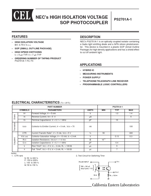
PART NUMBER PS2701A-1 SYMBOLS PARAMETERS UNITS MIN TYP MAX V F Forward Voltage, I F = 5 mA V 1.2 1.4I R Reverse Current, V R = 5 V µA 5 C t Terminal Capacitance, V = 0, f = 1 MHz pF 10I CEO Collector to Emitter Current, I F = 0 mA , V CE = 70 nA 100CTR Current Transfer Ratio 1, I F = 5 mA, V CE = 5 V % 50300 V CE (sat) Collector Saturation Voltage, I F = 10 mA, IC = 2 mA V 0.13 0.3 R I-O Isolation Resistance, V IN-OUT = 1 k V DC Ω 1011C I-O Isolation Capacitance, V = 0, f = 1 MH Z pF 0.4 t r Rise Time 2, V CC = 5 V, I C = 2 mA, R L = 100 Ω µs 5 t f Fall Time 2, V CC = 5 V, I C = 2 mA, R L = 100 Ω µs 7 Notes:1. CTR rank2. Test Circuit for Switching Time N: 50 to 300 % P: 150 to 300%L: 100 to 300 % M: 50 to 150 %NEC's HIGH ISOLATION VOLTAGESOP PHOTOCOUPLERFEATURES• HIGH ISOLATION VOLTAGE BV: 3.75 k V r.m.s.• SOP (SMALL OUT-LINE PACKAGE)• HIGH SPEED SWITCHING t r = 5 µs TYP , t f = 7 µs TYP• ORDERING NUMBER OF TAPING PRODUCTPS2701A-1-F3, F4DESCRIPTIONNEC's PS2701A-1 is an optically coupled isolator con t ain i ng a GaAs light emitting diode and a NPN silicon phototransis-tor. This device is mounted in a plastic SOP (Small Outline Package) for high density applications and has a shield effect to cut off ambient light.PS2701A-1ELECTRICAL CHARACTERISTICS (T A = 25°C)D i o d eT r a n s i s t o r C o u p l e d APPLICATIONS• HYBRID IC• MEASURING INSTRUMENTS • POWER SUPPLY• TELEPHONE/TELEGRAPH LINE RECEIVER • PROGRAMMABLE LOGIC CONTROLLERSCalifornia Eastern Laboratories元器件交易网PS2701A-1ANotes:1.Operation in excess of any one of these parameters may result in permanent damage.2.AC voltage for 1 minute at T A = 25 °C, RH = 60 % between input and ouput.ABSOLUTE MAXIMUM RATINGS 1 (T A = 25°C)TYPICAL PERFORMANCE CURVES (T A = 25 °C)DIODE POWER DISSIPATION vs.AMBIENT TEMPERATURED i o d e P o w e r D i s s i p a t i o n , P D (m W )Ambient Temperature, T A (°C) TRANSISTOR POWER DISSIPATION vs. AMBIENT TEMPERATURET r a n s i s t o r P o w e r D i s s i p a t i o n , P C (m W )Ambient Temperature , T A (°C) COLLECTOR CURRENT vs.COLLETOR TO EMITTER VOLTAGEF o r w a r d C u r r e n t , I F (m A )Collector to Emitter Voltage, V CE (V) C o l l e c t o r C u r r e n t , I C (m A )Collector Saturation Voltage, V CE (sat ) (V)COLLECTOR CURRENT vs.COLLECTOR SATURATION VOLTAGESYMBOLS PARAMETERSUNITS RATINGS PS2701A-1DiodeI F Forward Current (DC)mA 30V R Reverse VoltageV 6∆P D/ ºC Power Dissipation Derating mW/Ch 0.8P D Power Dissipation mW 80I F P Peak Forward Current(PW = 100 µs, Duty Cycle 1%)A0.5TransistorV CEOCollector to Emitter Voltage (I C = 1mA, I B = 0)V 70V ECO Emitter to Collector Voltage (I E = 100µA, I B = 0)V 5I C Collector CurrentmA 30∆P C/ºC Power Dissipation Derating mW/ºC 1.5P C Power Dissipation mW 150CoupledBV Isolation Voltage 2V r.m.s.3750T STG Storage Temperature °C -55 to +150T AOperating Ambient°C-55 to +1000.8 mW/ º C100806040200025507510012500501001502001.5mW ºC255075100125246810510152025301010.1元器件交易网COLLECTOR TO EMITTER DARK CURRENT vs. AMBIENT TEMPERATUREC o l l e c t o r t o E m i t t e rD a r k C u r r e n t , I CE O (n A )Ambient Temperature, T A (°C)CURRENT TRANSFER RATIO vs. FORWARD CURRENTC u r r e n t T r a n s f e r R a t i o , C T R (%)Forward Current, I F (mA)N o r m a l i z e d O u t p u t C u r r e n t , C T RAmbient Temperature, T A ( °C)NORMALIZED CURRENT TRANSFER RATIOvs. AMBIENT TEMPERATURESWITCHING TIME vs.LOAD RESISTANCES w i t c h i n g T i m e ,t (µs )Load Resistance, R L (Ω) SWITCHING TIME vs.LOAD RESISTANCES w i t c h i n g T i m e ,t (µs )Load Resistance, R L (Ω) FORWARD CURRENT vs. FORWARD VOLTAGEF o r w a r d C u r r e n t , I F (m A )Forward Voltage, V F (V)TYPICAL PERFORMANCE CURVES (T A = 25 °C)PS2701A-110000100010010102550751003002502001501005000.010.11101001.210.80.60.40-75-50-2502550751000.2100.111010010010001000010001001011101001.51.41.31.21.11.00.90.80.7元器件交易网PS2701A-1TYPICAL PERFORMANCE CURVES (T A = 25 °C)Frequency f, (KHz)N o r m a l i z e d G a i n , G vTime, HrC T R , (R e l a t i v e V a l u e )FREQUENCY RESPONSELONG TERM CTR DEGRADATIONOUTLINE DIMENSIONS(Units in mm)A Business Partner of NEC Compound Semiconductor Devices, Ltd.10/13/2003Life Support ApplicationsThese NEC products are not intended for use in life support devices, appliances, or systems where the malfunction of these products can reasonably be expected to result in personal injury. The customers of CEL using or selling these products for use in such applications do so at their own risk and agree to fully indemnify CEL for all damages resulting from such improper use or sale.PS2701A-1TOP VIEW1. Anode2. Cathode3. Emitter4. Collector10101010ORDERING INFORMATIONPART NUMBER PACKAGEPACKAGE STYLE PS2701A-1Magazine case 100 pcsPS2701A-1PS2701A-1-F3Embossed Tape 3500 pcs/reel PS2701A-1-F4PS2701A-1-V Magazine case 100 pcsPS2701A-1PS2701A-1-V-F3Embossed Tape 3500 pcs/reelPS2701A-1-V-F4元器件交易网。
07Ms201 (2)

07Ms201IntroductionIn this document, we will discuss the features, advantages, and applications of 07Ms201. We will explore the characteristics that make this product unique and valuable.Features1. High PerformanceOne of the key features of 07Ms201 is its high performance. It is designed to deliver exceptional results, particularly in demanding applications where superior performance is crucial. Whether it is processing complex calculations or handling data-intensive tasks, this product offers outstanding performance to meet the needs of various industries.2. Advanced Technology07Ms201 incorporates advanced technology to ensure optimal functionality. It is equipped with state-of-the-art components and cutting-edge software, enabling it to provide accurate and reliable results. The incorporation of advanced technology also translates into faster processing speeds and improved efficiency, making it a top choice for users seeking advanced solutions.3. User-Friendly InterfaceThis product prioritizes user experience by offering a user-friendly interface. The intuitive design and easy-to-navigate layout make it suitable for both beginner and experienced users. The user-friendly interface ensures that users can quickly learn to operate the product, maximizing productivity and reducing the learning curve.4. Versatility07Ms201 is a versatile product that can be used in various industries and applications. Whether it is data analysis, simulations, or complex calculations, this product can handle a wide range of tasks effectively. Its versatility makes it a reliable and flexible tool for professionals from different fields.Advantages1. Increased EfficiencyThe high performance and advanced technology of 07Ms201 contribute to increased efficiency. The product enables users to process and analyze large datasets quickly, reducing the time required for various tasks. By streamlining processes and eliminating bottlenecks, users can maximize productivity and achieve efficient workflows.2. Accuracy and ReliabilityAnother significant advantage of 07Ms201 is its accuracy and reliability. The incorporation of advanced technology ensures precise calculations and reliableresults, allowing users to make informed decisions based on accurate data. This advantage is particularly crucial in industries where precision is vital for success.3. Cost-Effective SolutionDespite its advanced features and high performance, 07Ms201 is a cost-effective solution. Its competitive pricing and value for money make it an attractive option for organizations and professionals looking for a reliable tool without breaking the bank. The cost-effectiveness of this product makes it accessible to a wide range of users and businesses.4. Seamless Integration07Ms201 seamlessly integrates with various systems and software, ensuring compatibility and ease of use. This advantageous feature allows users to incorporate the product into their existing workflow without major disruptions or additional expenses. The seamless integration contributes to the pr oduct’s versatility and adaptability.Applications1. Scientific Research07Ms201 finds extensive use in scientific research, where accurate calculations and data analysis are pivotal. Researchers can rely on the product’s high performance and advanced technology to process complex data sets and derive meaningful insights. The product’s versatility makes it suitable for various fields within scientific research, including physics, chemistry, and biology.2. Financial AnalysisIn the financial industry, 07Ms201 serves as a valuable tool for data analysis, risk assessment, and decision-making. Financial analysts can leverage the product’s accuracy and reliability to perform complex calculations and simulations, aiding in investment strategies, risk management, and forecasting. The user-friendly interface ensures that professionals without advanced technical skills can benefit from this powerful tool.3. Engineering and SimulationEngineers and designers can utilize 07Ms201 for simulations, modeling, and opti mization tasks. The product’s high performance and versatility enable engineers to analyze and test different scenarios, ensuring optimal designs and efficient processes. The accuracy and speed of calculations provided by 07Ms201 make it an ideal choice for engineering professionals.4. Data AnalyticsIn the era of big data, 07Ms201 plays a crucial role in data analytics. The product’s ability to handle large datasets and provide accurate results makes it a valuable asset for data scientists and analysts. With its advanced technology and high performance, users can extract meaningful insights and patterns from complex data, leading to informed decision-making and business growth.Conclusion07Ms201 is a powerful and versatile product that offers high performance, advanced technology, and a user-friendly interface. Its advantages, including increased efficiency, accuracy, cost-effectiveness, and seamless integration, make it an excellent choice for various applications. Whether it is scientific research,financial analysis, engineering, or data analytics, this product can significantly enhance productivity and deliver reliable results.。
- 1、下载文档前请自行甄别文档内容的完整性,平台不提供额外的编辑、内容补充、找答案等附加服务。
- 2、"仅部分预览"的文档,不可在线预览部分如存在完整性等问题,可反馈申请退款(可完整预览的文档不适用该条件!)。
- 3、如文档侵犯您的权益,请联系客服反馈,我们会尽快为您处理(人工客服工作时间:9:00-18:30)。
23
> Title of presentation - Date - References
23
MiCOM P12y 零序功率/ IeCosPHI保护
二段为定时限跳闸延时 最大灵敏角 c
Pe= Ve x Ie x Cos ( – c)
对 1/5A Ien自适应
K=1 (1A), K=5 (5A) IeCos( – c ) = Ve^Ie
5 °
25
> Title of presentation - Date - References
25
MiCOM P12y
电压保护
交流电压接线方式:
3 相相电压 2 相相电压+开口三角零序电压 2 相线电压 +开口三角零序电压
零序过电压保护 (59N)
一段门槛值 (Ue>>>>)
定时限 t_Ue>>>>
31
> Title of presentation - Date - References
31
MiCOM P12y
保持功能
32
> Title of presentation - Date - References
32
MiCOM P12y
闭锁逻辑原理
A
Lx 上游保护的动作时间可以被闭锁
B
闭锁信号是由下游的 继电器输出上游继电 器的输入来启动闭锁 逻辑 : •B 闭锁 A •C 闭锁 B
UA
/ AB
三相过/低电压保护(59) (27)
两段门槛 定时限 动作方式可选择 三相电压或任意一相电压
> ..> >
> = 1
U B/ BC
> ..> >
TRIP D ELA Y
U C/ CA
> ..> >
AN D / O R
Trip co m m a n d
&
A la rm
26
> Title of presentation - Date - References
26
MiCOM P12y
其他保护
低电流保护 (37)
一段 (I<) 门槛值 定时限
负序过流 (46)
三段门槛值 一段可设定反时限 IEC, ANSI/IEEE and RI curves are available 二、三段定时限
断线监测 (46 BC)
I2/I1 检测断线
t I2/I1 定时限
MiCOM P12y
自动化功能
MiCOM P127
功能
ANSI 代码 86
MiCOM P125
MiCOM P126
输出接点保持 选择逻辑 闭锁逻辑 断路器失灵保护 断路器监视及控制 自动重合闸 (4次)
50BF
79
35
MiCOM P12y
自动重合闸
外部闭锁 开关状态闭锁 外部闭锁 命令
过流保护, 零流保护 外部开关量输入
3 三相 4次 重合闸
AR 进行中 AR CB 合 AR 最后跳闸
36
> Title of presentation - Date - References
36
MiCOM P12y
自动重合闸
11
11
> Title of presentation - Date - References
MiCOM P12y
辅助功能
MiCOM P127
功能
ANSI 代码
MiCOM P125
MiCOM P126
测量 (实时有效值) 峰值和均值测量 瞬动记录 事件记录
方向/无方向过流馈线保护
MiCOM P12y
Jessie LI
Trainng Engineer
Shanghai,PRC. 22th,12,2005
2
> Title of presentation - Date - References
2
Overview
概述
MiCOM Protection
40 Range ...
MiCOM P12y
保护功能
功能
低电流保护
ANSI 代码
37
MiCOM P125
MiCOM P126
MiCOM P127
一次导线断线检测
46BC
负序过流保护
低电压
46
27
9
过电压 零序过电压
59 32N
9
> Title of presentation - Date - References
27
> Title of presentation - Date - References
27
MiCOM P12y
冷负荷起动
电流 上电期间的动作特性 正常负荷的特性 优点: 不需切换定值组 可靠只在上电期间起作用 应用: 给电动机供电的馈线 HV 变压器的零序接地保护 空调 电阻性加热器
上电时的 电流波形
18
MiCOM P12y
相间过流保护
正方向、反方向动作区域
动作条件:
Iphase 大于门槛值 Iphase在动作区
Trip ±定值:85° (以图示为例)
19
> Title of presentation - Date - References
19
MiCOM P12y
接地故障保护
极化电压Ue=U0 如果接线为3Vph,零序电压为算出值 如果接线为2Vpp+Vr或2Vph+Vr,零序电压为直接测量值 推荐RCA的整定值
V- V+ RLx 继电器A,B,C可以由相同的定值和时间
C
33
> Title of presentation - Date - References
33
MiCOM P12y
闭锁逻辑原理
关联此开入的功能
34 > Title of presentation - Date - References 34
Va Ie
Va
中性点接地系统示例
Ve
Vc
RCA
Vb
20
> Title of presentation - Date - References
20
MiCOM P12y
接地故障保护
正方向、反方向动作区域
动作条件:
Ie 大于门槛值 Ie在动作区
21
> Title of presentation - Date - References
MiCOM P127
三相过流保护(带方向) 接地故障保护(带方向)
67 50N/51N/ 67N 32N
8
零序功率/ I cosF 热过负荷 冷负荷起动
49
8
> Title of presentation - Date - References
跳闸区域固定为RCA 85°
24
> Title of presentation - Date - References
24
MiCOM P12y 零序功率/ IeCosPHI保护
P/Iecos
最大灵敏角 (RCA)
极化电压
Icos 1 C
5 °
1 Icos 2 2
正向区域
Q/Iesin 反向区域
10
10
> Title of presentation - Date - References
MiCOM P12y
辅助功能
MiCOM P127
功能
ANSI 代码
MiCOM P125
MiCOM P126
跳闸回路断线检测 复压闭锁过流 与逻辑方程 定值组 2
51V
2 2
诊断/ 装置自检 MiCOM S1 支持
P126: 三相及方向/无方向接地故障保护 P127: 全面的三相以及接地故障保护
7
> Title of presentation - Date - References
7
MiCOM P12y
保护功能
功能 三相过流保护(无方向)
ANSI 代码 50/51
MiCOM P125
MiCOM P126
17
MiCOM P12y
相间过流保护
极化电压的门槛
0.6V(PT额定57-130V) 3V (PT额定220-480V)
出口故障,极化电压小
单相和两相相间故障: 交叉极化 三相故障:极化量记忆(同步极化) 极化电压连续低于门槛5s,闭锁方向过流
18
> Title of presentation - Date - References
5
MiCOM Px20
设置简单
特点
1A/5A 双额定CT输入
LED指示灯 可编程
灵活的通讯
全面的记录功能
输入/输出 可编程
可抽出式装置
MiCOM40-6 6 > Title of presentation - Date - References
6
MiCOM P12y
型号列表
P125: 方向/无方向单相及接地故障保护
tBF
Trip order
29
> Title of presentation - Date - References