挡土墙外文文献
土木工程专业毕业设计外文文献及翻译
土木工程专业毕业设计外文文献及翻译Here are two examples of foreign literature related to graduation design in the field of civil engineering, along with their Chinese translations:1. Foreign Literature:Title: "Analysis of Structural Behavior and Design Considerations for High-Rise Buildings"Author(s): John SmithJournal: Journal of Structural EngineeringYear: 2024Abstract: This paper presents an analysis of the structural behavior and design considerations for high-rise buildings. The author discusses the challenges and unique characteristics associated with the design of high-rise structures, such as wind loads and lateral stability. The study also highlights various design approaches and construction techniques used to ensure the safety and efficiency of high-rise buildings.Chinese Translation:标题:《高层建筑的结构行为分析与设计考虑因素》期刊:结构工程学报年份:2024年2. Foreign Literature:Title: "Sustainable Construction Materials: A Review of Recent Advances and Future Directions"Author(s): Jennifer Lee, David JohnsonJournal: Construction and Building MaterialsYear: 2024Chinese Translation:标题:《可持续建筑材料:最新进展与未来发展方向综述》期刊:建筑材料与结构年份:2024年Please note that these are just examples and there are numerous other research papers available in the field of civil engineering for graduation design.。
建筑 土木工程 外文翻译 外文文献 英文文献及译文 土工织物加筋垫层加固软土地基

Geotextile reinforced by soft soil1. IntroductionGeotextile known, it has high tensile strength, durability, corrosion resistance, texture, flexibility, combined with good sand, to form reinforced composite foundation, effectively increase the shear strength , tensile properties, and enhance the integrity and continuity of soil. Strengthening mechanism for the early 60's in the 20th century, Henri Vidal on the use of triaxial tests found a small amount of fiber in the sand, the soil shear strength can improve the image of more than 4 times in recent years, China's rock Laboratory workers also proved in the reinforced sand can effectively improve the soil's bearing capacity, reduce the vertical ground settlement, effectively overcome the poor soil and continuity of overall poor performance. As with the above properties of reinforced soil and the characteristics of its low price, so the project has broad application prospects.2.1 Project OverviewThe proposed retaining wall using rubble retaining wall of gravity, the wall is 6 meters high, the bearing capacity of foundation soil required to 250kPa, while the basement geology from the top down as follows: ①clay to a thickness of 0.7 to 2 meters saturated, soft plastic; ② muddy soil, about 22 - 24 meters thick, saturated, mainly plastic flow, local soft plastic; ③ sand layer to a thickness of 5 to 10 meters, containing silty soil and organic matter, saturated, slightly wet; ④ gravel layer, the thickness of the uneven distribution points, about 0 to 2.2 meters, slightly dense; ⑤ weathered sandstone. Including clay and silty soil bearing capacity is 70kPa, obviously do foundation reinforcement.2.2 Enhanced Treatment of reinforced foundation cushion Reinforcement replacement method can be used for sand and gravel used forsoil treatment, but due to loose bedding, based on past experience, witha gravel mat to treat a large settlement of the foundation always exist, even the characteristics of poor, often resulting in cracks in the superstructure, differential settlement of the image, this works for6-meter-high rubble retaining walls, height and large, and because the walls are 3 meters high wall, if there is differential settlement of retaining walls, cracks, will result in more serious consequences and thus should be used on the cushion reinforcement through economic and technical analysis, decide on the sand and gravel stratum were reinforced hardening. Reinforcement treatment method: first the design elevation and the basement excavation to 200mm thick layer of gravel bedding, and then capped with a layer of geotextile, and then in the thick sand and gravel on the 200, after leveling with the yellow sand using roller compaction; second with loaded bags of sand and gravel laying of geotextile, the gap filled with slag, geotextile bags capped 100 thick gravel, roller compaction. Its on repeat laying geotextile → → compacted gravel, until the design thickness of the cushion, the bridge is 1 m thick cushion, a total of 4 layers of geotextile, two bags of sand.This method works fast, simple machine, investment, after years of use, that reinforce good effect, building and construction units are satisfied.3 ExperienceTo achieve the reinforced soil reinforcement effect, must be reinforced earth construction technology, construction strict quality control: 1, geotextile should increase the initial pre-stress, and its end should be a reliable anchor to play the tensile strength of geotextile, anchoring more firmly, more capacity to improve, the foundation of the stress distribution more uniform, geotextile side Ministry of fixed length by laying end to ensure the fold, the folded end wrapped sand to increase its bond strength to ensure that the use will not be pulled out duringthe period.Second, the construction process have a significant effect on the reinforcement effect, the construction should be as soon as possible so that geotextile in tension, tensile strength geotextile can be played only when the deformation, so do not allow construction of geotextile crease occurs, the earth Fabric tension leveling as much as possible. Geotextile in order to have enough by the early Dutch strain, according to the following procedure works: ① laying geotextile; ② leveled the tension at both ends; both ends of the folded package gravel and sand filling at both ends; ③ center fill sand; ④ 2 higher end of sand; ⑤ Finally, the center of sand filling. Click here to enable the construction method of forming corrugated geotextile being stretched as soon as possible, to play a role in the early loaded.Third, the construction of geotextile-reinforced cushion should the level of shop using geotextile geotextile and laying of gravel bags cushion the turn to play bag cushion integrated turn out good, flexural rigidity, and dispersion of good and peace bedding layer of the overall continuity of good advantages.4 ConclusionGeotextile reinforced by soft soil is an effective, economical, safe, reliable, simple method, but the literature describes only qualitative, experience more components, yet the lack of rigorous The theoretical formula, reliable test data to be adequate, these are yet to be theoretical workers and the general engineering and technical personnel continue to explore.土工织物加筋垫层加固软土地基1. 引言土工织物又称土工聚合物,它具有高抗拉强度,耐久性、耐腐蚀性,质地柔韧,能与砂土很好地结合,组合成加筋土复合地基,有效地提高土的抗剪强度、抗拉性能,增强土体的整体性和连续性。
土木工程英文文献

土木工程英文文献Civil engineering is a branch of engineering that deals with the design, construction, and maintenance of infrastructure such as buildings, roads, bridges, airports, tunnels, and water supply systems. It is considered one of the oldest branches of engineering and has a strong influence on the development of society.The focus of civil engineering is to create safe and efficient infrastructure for human use. Civil engineers use a variety of techniques and tools to analyze the requirementsof a project, design the infrastructure, and oversee the construction process. This involves taking into account a variety of factors such as environmental conditions, materials availability, and cost.The field of civil engineering is constantly evolving as new techniques and tools are developed. Many civil engineers today use computer software to aid in the design process, allowing for more accurate and efficient designs. Additionally, new materials and construction methods are being developed that offer greater strength and durability.One area of civil engineering that has seen significant growth in recent years is sustainable design. With concerns about climate change and resource depletion, there has been an increased focus on creating infrastructure that is environmentally friendly and resource efficient. Civil engineers are working to develop designs that reduce energy consumption, minimize waste, and utilize renewable resources.Despite the challenges and complexities of civilengineering, it remains a highly rewarding and important field. Civil engineers play a vital role in shaping the world we live in and improving the quality of life for people around the globe. Whether designing a new building or developing a water supply system, civil engineers work tirelessly to ensure that infrastructure is safe, efficient, and sustainable.。
土力学挡土墙英文教材
Geotechnics 3: Retaining wall design
3
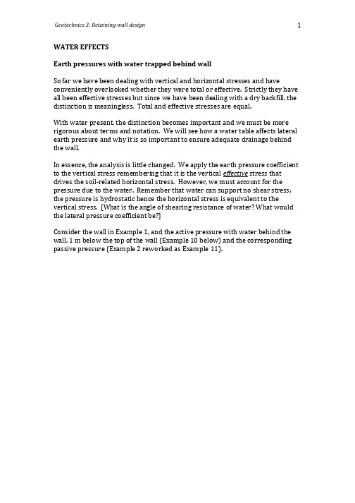
Example 11: Passive earth pressure calculation with water table A 6 m high smooth vertical retaining wall with horizontal backfill and water behind to a level 1 m below top of the wall is shown. Determine the equivalent force (per metre run) in the passive state and the lines of action if the soil properties are: = 16 kN/m3 above water table; 18 kN/m3 below water table; c = 0 kN/m2; = 36
Geotechnics 3: Retaining wall design
1
WATER EFFECTS Earth pressures with water trapped behind wall So far we have been dealing with vertical and horizontal stresses and have conveniently overlooked whether they were total or effective. Strictly they have all been effective stresses but since we have been dealing with a dry backfill, the distinction is meaningless. Total and effective stresses are equal. With water present, the distinction becomes important and we must be more rigorous about terms and notation. We will see how a water table affects lateral earth pressure and why it is so important to ensure adequate drainage behind the wall. In essence, the analysis is little changed. We apply the earth pressure coefficient to the vertical stress remembering that it is the vertical effective stress that drives the soil-related horizontal stress. However, we must account for the pressure due to the water. Remember that water can support no shear stress; the pressure is hydrostatic hence the horizontal stress is equivalent to the vertical stress. [What is the angle of shearing resistance of water? What would the lateral pressure coefficient be?] Consider the wall in Example 1, and the active pressure with water behind the wall, 1 m below the top of the wall (Example 10 below) and the corresponding passive pressure (Example 2 reworked as Example 11).
双面加筋土挡土墙外文文献翻译

Mechanical performance of a double—face reinforced retaining wall in an area disturbed by mining Abstract: The application of a double—face reinforced retaining wall during road construction can reduce engineering costs, speed road paving and have a good influence on environment。
An ABAQUS numerical model of a double-face reinforced retaining wall was built. The influence of surface subsidence induced by mining was considered. A physical model test was also performed in the laboratory on a reinforced retaining wall。
The influence' of subsidence induced by mining was observed。
The numerical results match measurements in the laboratory very well。
The vertical pressure on the base of the retaining wall, the horizontal displacement of the wall and the horizontal soil pressure acting on the wall were analyzed。
土木工程英文参考文献

Introduction to Civil Engineering PapersCivil Engineering for the development of a key role, first as a material foundation for the civil engineering construction materials, followed by the subsequent development of the design theory and construction technology. Every time a new quality of building materials, civil engineering will be a leap-style development.People can only rely on the early earth, wood and other natural materials in the construction activities, and later appeared in brick and tile that artificial materials, so that the first human to break the shackles of natural building materials. China in the eleventh century BC in the early Western Zhou Dynasty created the tile. The first brick in the fifth century BC to the third century BC, when the tomb of the Warring States Period. Brick and tile better than the mechanical properties of soil, materials, and easy to manufacture. The brick and tile so that people began to appear widely, to a large number of housing construction and urban flood control project, and so on. This civil engineering technology has been rapid development. Up to 18 to the 19th century, as long as two thousand years, brick and tile has been a major civil engineering construction materials, human civilization has made a great contribution to the even was also widely used in the present.The application of a large number of steel products is the second leap in civil engineering. Seventeen 1970s the use of pig iron, the early nineteenth century, the use of wrought iron bridges and the construction of housing, which is a prelude to the emergence of steel. From the beginning of the mid-nineteenth century, metallurgical industry, smelting and rolling out high tensile and compressive strength, ductility, uniformity of the quality of construction steel and then produce high-strength steel wire, steel cables. As a result of the need to adapt to the development of the steel structure have been flourishing. In addition to the application of the original beam, arch structure, the new truss, a framework, the structure of network, cable structures to promote the gradual emergence of the structure of Yan in the form of flowers.From the brick building long-span structures, stone structures, a few meters of wood, steel structure to the development of tens of meters, a few hundred meters, until modern km above. So in the river, cross the bridge from shelves, on the ground since the construction of skyscrapers and high-rise tower, even in the laying of underground railway, to create an unprecedented miracle.In order to meet the needs of the development of steel works, on the basis of Newton's mechanics, material mechanics, structural mechanics, structural engineering design theory came into being, and so on. Construction machinery, construction technology and construction organization design theory also development, civil engineering from the experience of rising to become science, engineering practice and theoretical basis for both is a different place, which led to more rapid development of civil engineering. During the nineteenth century, 20, made of Portland cement, concrete has come out. Concrete can aggregate materials, easy-to-concrete structures forming, but the tensile strength of concrete is very small, limited use. By the middle of the nineteenth century, the surge in steel production, with the emergence of this new type of reinforced concrete composite construction materials, which bear the tension steel, concrete bear the pressure and play their own advantages. Since the beginning of the 20th century,reinforced concrete is widely used in various fields of civil engineering.From the beginning of the 1930s, there have been pre-stressed concrete. Pre-stressed concrete structure of the crack resistance, rigidity and carrying capacity, much higher than the reinforced concrete structure, which uses an even wider area. Civil Engineering into the reinforced concrete and prestressed concrete dominant historical period. Concrete buildings to bring about the emergence of new economic, aesthetic structure in the form of engineering, civil engineering so that a new construction technology and engineering design of the structure of the theory. This is another leap in the development of civil engineering.A project to build the facilities in general to go through the investigation, design and construction in three stages, require the use of geological prospecting projects, hydro-geological survey, engineering survey, soil mechanics, mechanical engineering, engineering design, building materials, construction equipment, engineering machinery, building the economy , And other disciplines and construction technology, construction and other fields of knowledge, as well as computer and mechanical testing techniques. Civil engineering is therefore a broad range of integrated disciplines. With the progress in science and technology development and engineering practice, the civil engineering disciplines have also been developed into a broad connotation, the number of categories, the structure of complex integrated system.Civil Engineering is accompanied by the development of human society developed. It works in the construction of facilities reflect the various historical periods of socio-economic, cultural, scientific, technological development outlook, which civil society has become one of the historical development of the witness.In ancient times, people began to build simple houses, roads, bridges and still water channel to meet the simple life and production. Later, in order to adapt to the war, production and dissemination of religious life, as well as the needs of the construction of the city, canals, palaces, temples and other buildings.Many well-known works shown in this historical period of human creativity. For example, the Great Wall of China, Dujiangyan, the Grand Canal, Zhaozhou Bridge, Yingxian Wooden Tower, the pyramids of Egypt, Greece's Parthenon, Rome's water supply project, colosseum amphitheater (Rome large animal fighting Field), as well as many other well-known churches, palaces and so on.After the industrial revolution, especially in the 20th century, on the one hand, civil society to put forward a new demand; On the other hand, all areas of society for the advancement of civil engineering to create good conditions. Thus this period of civil engineering has been advanced by leaps and bounds. All over the world there have been large-scale modernization of industrial plants, skyscrapers, nuclear power plants, highways and railways, long-span bridges, and large-diameter pipelines long tunnel, the Grand Canal, the big dams, airports, port and marine engineering, etc. . For civil engineering continually modern human society to create a new physical environment, human society, modern civilization has become an important part.Civil Engineering is a very practical subjects. In the early days, through the civil engineering practice, summing up successful experience, in particular, to draw lessons from the failure of developed. From the beginning of the 17th century, with Galileo andNewton as a pilot with the mechanics of the modern civil engineering practice, gradually formed the mechanical, structural mechanics, fluid mechanics, rock mechanics, civil engineering as the basis of theoretical subjects. This experience in civil engineering from the gradually developed into a science.In the course of the development of civil engineering, engineering practice often first experience in theory, engineering accidents often show a new unforeseen factors, triggering a new theory of the research and development. So far a number of projects dealing with the problem, is still very much rely on practical experience.Civil Engineering Technology with the main reason for the development of engineering practice and not by virtue of scientific experiments and theoretical studies, for two reasons: First, some of the objective situation is too complicated and difficult to faithfully carry out laboratory or field testing and analysis. For example, the foundation, tunnel and underground engineering and deformation of the state and its changes over time, still need to refer to an analysis of engineering experience to judge. Second, only a new engineering practice in order to reveal new problems. For example, the construction of a high-rise buildings, high-rise tower and mast-span bridges, wind and earthquake engineering problems highlighted in order to develop this new theory and technology.In the long-term civil engineering practice, it is not only building great attention to the arts, has made outstanding achievements; and other works, but also through the choice of different materials, such as the use of stone, steel and reinforced concrete, with natural Environmental art in the construction of a number of very beautiful, very functional and good works. Ancient Great Wall of China, the modern world, many of the television tower and the bridge ramp Zhang, are cases in point.A building is closely bound up with people,for it provides with the necessary space to work and live in .As classified by their use ,buildings are mainly of two types :industrial buildings and civil buildings .industrial buildings are used by various factories or industrial production while civil buildings are those that are used by people for dwelling ,employment ,education and other social activities .Industrial buildings are factory buildings that are available for processing and manufacturing of various kinds ,in such fields as the mining industry ,the metallurgical industry ,machine building ,the chemical industry and the textile industry . factory buildings can be classified into two types single-story ones and multi-story ones .the construction of industrial buildings is the same as that of civil buildings .however ,industrial and civil buildings differ in the materials used and in the way they are used .Civil buildings are divided into two broad categories: residential buildings and public buildings .residential buildings should suit family life .each flat should consist of at least three necessary rooms : a living room ,a kitchen and a toilet .public buildings can be used in politics ,cultural activities ,administration work and other services ,such as schools, office buildings, parks ,hospitals ,shops ,stations ,theatres ,gymnasiums ,hotels ,exhibition halls ,bath pools ,and so on .all of them have different functions ,which in turn require different design types as well.Housing is the living quarters for human beings .the basic function of housing is to provide shelter from the elements ,but people today require much more that of theirhousing .a family moving into a new neighborhood will to know if the available housing meets its standards of safety ,health ,and comfort .a family will also ask how near the housing is to grain shops ,food markets ,schools ,stores ,the library ,a movie theater ,and the community center .In the mid-1960’s a most important value in housing was sufficient space both inside and out .a majority of families preferred single-family homes on about half an acre of land ,which would provide space for spare-time activities .in highly industrialized countries ,many families preferred to live as far out as possible from the center of a metropolitan area ,even if the wage earners had to travel some distance to their work .quite a large number of families preferred country housing to suburban housing because their chief aim was to get far away from noise ,crowding ,and confusion .the accessibility of public transportation had ceased to be a decisive factor in housing because most workers drove their cars to work .people we’re chiefly interested in the arrangement and size of rooms and the number of bedrooms .Before any of the building can begin ,plans have to be drawn to show what the building will be like ,the exact place in which it is to go and how everything is to be done.An important point in building design is the layout of rooms ,which should provide the greatest possible convenience in relation to the purposes for which they are intended .in a dwelling house ,the layout may be considered under three categories : “day”, “night” ,and “services” .attention must be paid to the provision of easy communication between these areas .the “day “rooms generally include a dining-room ,sitting-room and kitchen ,but other rooms ,such as a study ,may be added ,and there may be a hall .the living-room ,which is generally the largest ,often serves as a dining-room ,too ,or the kitchen may have a dining alcove .the “night “rooms consist of the bedrooms .the “services “comprise the kitchen ,bathrooms ,larder ,and water-closets .the kitchen and larder connect the services with the day rooms .It is also essential to consider the question of outlook from the various rooms ,and those most in use should preferably face south as possible .it is ,however ,often very difficult to meet the optimum requirements ,both on account of the surroundings and the location of the roads .in resolving these complex problems ,it is also necessary to follow the local town-planning regulations which are concerned with public amenities ,density of population ,height of buildings ,proportion of green space to dwellings ,building lines ,the general appearance of new properties in relation to the neighbourhood ,and so on . There is little standardization in industrial buildings although such buildings still need to comply with local town-planning regulations .the modern trend is towards light ,airy factory buildings .generally of reinforced concrete or metal construction ,a factory can be given a “shed ”type ridge roof ,incorporating windows facing north so as to give evenly distributed natural lighting without sun-glare .。
science derect重力式挡土墙

Technical NoteSeismic stability analysis of gravity retaining wallsXinpo Li a,b ,Yong Wu b ,Siming He a,b,Ãa Key Laboratory of Mountain Hazards and Surface Process,CAS,Chengdu 610041,China bInstitute of Mountain Hazards and Environment,CAS,Chengdu 610041,Chinaa r t i c l e i n f oArticle history:Received 22September 2009Received in revised form 1February 2010Accepted 3April 2010Keywords:Seismic stability Limit analysisGravity retaining walls Yield accelerationa b s t r a c tA new approach based on the category of upper bound theorem of limit analysis is presented in this study to consider the seismic stability of gravity retaining walls.The retaining wall and the backfill soil were taken as a whole system.For a translational failure mechanism assumed,formulas are provided to calculate directly the yield acceleration and the inclination of the failure surface.An example is shown to illustrate the parisons are made with limit equilibrium method,and the results are found consistent.Based on a limited parametric study,it is shown that the wall roughness has remarkable influence on the yield acceleration.&2010Elsevier Ltd.All rights reserved.1.IntroductionGravity walls are widely used as earth retaining systems supporting fill slopes adjacent to roads and residential areas,also in regions prone to earthquake.Many researchers have developed design methods for retaining walls during earthquakes by using different approaches.Though the quest for rational design methods of retaining structures has been pursued for several decades,deformations ranging from slight displacement to catastrophic failure have been observed in many earth retaining structures during the recent major earthquakes,including the 1999Ji-Ji earthquake [1],the 2004Chuetsu earthquake [2],and the 2008Wenchuan earthquake [3].To date,the theoretical approach is the most widely used method to analyze seismic stability of earth retaining structures.The majority of the methods used by practitioners usually require estimating the earth pressure behind the wall and expressing the stability of soil structure by a factor of safety.The effect of earthquake is represented pseudo-statically by an approximate static force acting in the horizontal direction.To compute the active earth thrust acting against retaining walls in seismic conditions,the Mononobe–Okabe method or its extensions are most widely used [4–6].The Mononobe–Okabe solution treats earthquake loads as pseudo-dynamic,generated by uniform acceleration in the backfill.The retained soil is considered as perfect plastic material,which fails along a planar surface,thereby exerting a limit thrust on the wall.The method has prevailed mainlydue to its simplicity and the familiarity of engineers with the Coulomb method.However,the Mononobe–Okabe method presents a basic shortcoming:the solution is based on the limit equilibrium of the soil wedge without taking into account the presence of the wall.Caltabiano et al.[7]suggested a new solution based on the pseudo-static equilibrium of the soil–wall system and applied it to soil–wall systems with surcharged backfills.More recently,Mylonakis et al.[8]presented a stress plasticity solution for determining gravitational and earthquake-induced earth pressures on gravity walls retaining cohesionless soil.The solution is essentially an approximate slip line approach,based on the theory of discontinuous stress fields,and takes into account the following parameters:(1)weight and friction angle of the soil material,(2)wall inclination,(3)backfill inclination,(4)wall roughness,(5)surcharge at soil surface,and (6)horizontal and vertical seismic acceleration.The finite element method is certainly the most comprehen-sive approach to analyze the performance of soil structures subjected to seismic loading.Psarropoulos et al.[9]utilized the finite-element method to study the dynamic earth pressures developed on rigid or flexible non-sliding retaining walls.And more recently,a two-dimensional,effective-stress finite element procedure in conjunction with a generalized elasto-plastic constitutive model,with slight modifications,was conducted by Alyami et al.[10].Certainly,the finite element method has some advantages in considering the natural failure mechanisms and the interaction of structure–soil system,however,its use usually requires high numerical costs and accurate measurements of the properties of the component materials,which are often difficult to achieve.This makes the use of finite element method not very attractive for current applications.Contents lists available at ScienceDirectjournal homepage:/locate/soildynSoil Dynamics and Earthquake Engineering0267-7261/$-see front matter &2010Elsevier Ltd.All rights reserved.doi:10.1016/j.soildyn.2010.04.005ÃCorresponding author.E-mail address:hsm112003@ (S.He).Soil Dynamics and Earthquake Engineering 30(2010)875–878As well known,design based on pseudo-static approach is generally considered conservative,since even when the safety factor drops below one the soil structure could experience only a finite displacement rather than a complete failure[11,12].Over the past several decades,analytical methods have been developed to estimate the displacement of retaining walls under earthquake loading for specific applications.Richards and Elms[4]formerly employed the Newmark procedure in evaluations of earthquake-induced displacements of gravity retaining walls.A design procedure based on a tolerable displacement against sliding was proposed by Ling et al.[13].They employed the Newmark’s sliding block method to evaluate permanent displacement of reinforced slopes during earthquakes.And the same approach has been extended by Ling and Leshchinsky[14]to include the vertical component of ground acceleration.More recently, Trandafir et al.[2]conducted a displacement approach for the seismic stability of gravity retaining walls based on the sliding block concept.In order to solve a limit state problem,limit analysis is also an effective methodology.The upper bound approach of limit analysis was used by Chen[15],ˇSkrabl and Macuh[16],and Yang [17]to consider the problem of earth pressures.And more recently,a method based on limit analysis for calculations of yield acceleration and seismic displacements of multi-block structures (including retaining wall)was suggested by Michalowski[18].In the present study,the upper bound approach of limit analysis is applied to calculate the yield acceleration for gravity retaining walls undergoing direct sliding failure.The retaining wall and the backfill soil were taken as a whole system.In the framework of limit analysis,a simple block approach was used to solve the seismic stability of the system.The computed results of yield acceleration are compared with that of limit equilibrium method.The closed-form solution may be found useful by engineers in the displacement-based seismic design of retaining walls.2.Theoretical model of analysisThe analysis of the seismic stability of walls retaining backfill soil is based on the following assumptions:(1)the wall–soil system is long enough for the end effects to be ignored(plane strain condition);(2)the soil is homogeneous,dry,and cohesion-less;(3)the retaining wall can be subjected only to horizontal displacements;(4)the seismic action is uniform horizontally distributed in the whole mass of the system;and(5)the failure wedge is a plain.Furthermore,the upper bound limit analysis is based on the assumption that soil will be deformed according to the associatedflow rule and the convexity of the soil yield condition.In the following analysis,we assumed that these conditions are met.The possible failure modes considered in this work is direct sliding mechanism which is illustrated in Fig.1(a).In this failure mechanism,the gravity wall slides over the bottom layer once the ground acceleration threshold for slide is exceeded.It should be noted that the retaining wall herein is idealized as constructing directly on the ground surface,but in reality,massive retaining walls always have some embedment depth.The upper bound theorem of limit analysis states that the soil–wall system will start to slide under its own weight plus inertia force induced by earthquake and any other loads,if the rate of work done by the external forces exceed the rate of internal energy dissipation for any assumed kinematically admissible failure mechanism.So,the yield acceleration factor k c can be given by equating the rate of external work to the rate of energy dissipation.The failure mode shown in Fig.1(a)consists of two wedges,the soil wedge and the retaining wall wedge.This failure mechanism is geometrically specified by wall height H,backfill soil slope a, and the angle that planar failure surface makes with the horizontal b.The rate of work done by the gravity forces is the vertical component of the velocities multiplied by the weight of the wedges_Wg¼W s V0sinðbÀjÞÀW w V1sin d bð1Þwhere W s and W w indicate the weight of soil wedge and retaining wall,respectively,and d b is friction angle between retaining wall and the base.Once the system is subjected to horizontal seismic loading,the rate of the inertial force needs to be accounted for in the energy balance equation.It can be calculated analogously to the rate of work of the soil weight,and be written as_Ws¼k h W s V0cosðbÀjÞþk h W w V1cos d bð2Þwhere k h is seismic coefficient representing horizontal accelera-tion as a fraction of the gravity acceleration.Since there is no cohesion along the slip surface and the retaining wall base,energy dissipation is zero,the energy balance equation yieldsW s V0sinðbÀjÞþk y W s V0cosðbÀjÞÀW w V1sin d bþk y W w V1cos d b¼0ð3Þwhere k y is the yield acceleration coefficient of the failure mechanism with respect to angle b.For a kinematically admissible failure mechanism,some relationship should be satisfied between the velocities V0and the V1.Let us observe the two adjoining wedges as shown in Fig.1(b).The left and right wedges move with the absolute velocities V1and V0which incline at angles d b and j to their bases,respectively.The relative velocity of the left wedge with respect to the right one along the interface is represented as V01, which inclines at an angle d.To allow the velocities assigned to the wedge failure mechanism to be kinematically compatible,the two adjoining wedges must not move to cause overlap or indentation.This implies that the velocity hodograph must be closed,i.e.,V0þV01¼V1ð4ÞFrom Eq.(4)and Fig.1(b),we obtainV0¼V1cosðd bþdÞcosðjþdÀbÞð5Þwhere d is friction angle between retaining wall and backfill soil.Substituting Eq.(5)into Eq.(3)and rearranging the terms leads to the following expression for k y:k y¼W w sin d bÀW sðcosðd bþdÞ=cosðjþdÀbÞÞsinðbÀjÞwd b s d b d j d b b jð6ÞThe critical seismic coefficient is obtained by minimising k y, with respect to b.This means that taking thefirst derivatives of k y and equating them to zero,i.e.(q k y/q b)¼0.Solving this equation and substituting the value of b,the least upper bound value of yield acceleration factor is calculated.This critical value of k y is indicated in the following text as k c.parable models in literaturesIt is instructive to compare the values of k c calculated by means of the expressions derived in the previous sections to those obtained from other solutions publishing in the literature in order to show the possible differences.Several plots have been recently published to illustrate the effect of seismic forces on the stability of gravity retaining walls.A pseudostatic type of the rotating block method was developed by Zeng and Steedman[6]to calculate the permanent rotational displacement of gravity retaining walls under earth-quake loading.The model is similar to the sliding block method of Newmark,which defines a threshold acceleration in rotation,and each time this threshold acceleration is exceeded,permanent rotation is accumulated.And the model was validated by comparison with data from centrifuge model tests.At the same time,they also gave a method to calculate the critical acceleration coefficient for lateral sliding.For the wall shown in Fig.2(a),at the instant when sliding starts,equilibrium of forces in the horizontal direction givesk y W wþP AE cos d¼ðW wþP AE sin dÞtan d bð7Þwhere P AE is the dynamic earth pressure acting on the retaining wall.P AE and its acting point can be determined by the Mononobe–Okabe solution.Caltabiano et al.[7]presented a new solution based on the pseudostatic equilibrium analysis of the soil–wall system with surcharge backfills.The soil–wall system considered in their analysis is as shown in Fig.2(b).At failure,the equilibrium between resisting and driving forces is given by the expression: W w tan d bÀk y W w¼W s½k yþtanðbÀjÞ ð8ÞThe critical seismic coefficient k c is obtained similarly by minimising k y,with respect to b.4.Illustrative examples and discussions4.1.Illustrative exampleA gravity wall made of concrete and supporting dry backfill is shown in Fig.3.The wall is constrained to horizontal slide only.The yield acceleration factors for slide can be determined Using Eqs.(7) and(8),and the approach of this study are0.236,0.112,and0.236, respectively.It is noted that limit analysis gives the same valueofyield acceleration factor with Eq.(7)in which the dynamic earth pressure was calculated by Mononobe–Okabe’s solution. Actually,the results of Eq.(7)equal to that of limit analysis using a translational failure mechanism.Though,in this case,the upper-bound theorem of limit analysis yields the same results as the limit equilibrium method,the two methods are very different.The equivalence of the results for limit load problems obtained using the upper-bound theorem of limit analysis and the limit equilibrium method has been mentioned in the literature on a few occasions [15,19,20],and was discussed in detail by Michalowski in one of his studies[20].4.2.Effect of friction angle between retaining wall and backfill soilFig.4shows the influence of the friction angle between retaining wall and backfill soil on the critical seismic coefficient k c and failure surface in the cases of a¼01,d b¼j¼251,301,351,and 401.In thefigure,k c is calculated using Eq.(6)and plotted against the dimensionless abscissa l which is defined asl¼djð9Þwhere0p l p1.That is to say,the friction of wall back is limited to a range between0and j.As can be expected,k c increases with increasing l,and b decreases with increasing l.It can be seen that the roughness of wall back has a remarkable effect on the yield acceleration factors of the gravity retaining wall.As the case of j¼301,k c increases dramatically from0.112 for smooth wall with l¼0to0.236for rough wall with l¼1.0.So in the design of retaining wall under earthquake loading,wall roughness should be taken into account properly.5.ConclusionsThis work attempts to develop a method to analyze the seismic stability of gravity retaining walls with backfill under the category of upper bound theorem of limit analysis.For a translational failure mechanism assumed,closed-form solutions are derived that are based on the soil–wall system analysis.The expressions derived in this paper can be conveniently used to calculate the critical acceleration factor,k c,which is a key parameter to evaluate the seismic stability of gravity retaining walls.The conducted illustrative example calculation showed coincidence between the proposed method and that from classical Mono-nobe–Okabe solutions.Ultimately,the influence of wall roughness on the critical acceleration factor was analyzed.It is expected that this limit analysis method can be useful in current applications because of its simplicity and reasonability.AcknowledgementsThis research has receivedfinancial supports from the973 Program of China(Grant no.2008CB425802),and the West Light Foundation of The CAS(Grant no.09R2200200).These supports are greatly appreciated.References[1]Ling HI,Leshchinsky D,Chou NNS.Post-earthquake investigation on severalgeosynthetic-reinforced soil retaining walls and slopes during the Ji-Ji earthquake of Taiwan.Soil Dynamics and Earthquake Engineering2001;21: 297–313.[2]Trandafir AC,Kamai T,Sidle RC.Earthquake-induced displacements of gravityretaining walls and anchor-reinforced slopes.Soil Dynamics and Earthquake Engineering2009;29:428–37.[3]Han Q,Du X,Liu J,Li Z,Li L,Zhao J.Seismic damage of highway bridges duringthe2008Wenchuan earthquake.Earthquake Engineering and Engineering Vibration2009;8(2):263–73.[4]Richards R,Elms DG.Seismic behavior of gravity retaining walls.Journal ofthe Geotechnical Engineering Division1979;105(GT4):449–64.[5]Nadim F,Whitman RV.Seismically induced displacement of retaining walls.Journal of Geotechnical Engineering1983;109(7):915–31.[6]Zeng X,Steedman RS.Rotating block method for seismic displacement ofgravity walls.Journal of Geotechnical and Geoenvironmental Engineering 2000;126(8):709–17.[7]Caltabiano S,Cascone E,Maugeri M.Seismic stability of retaining walls withsurcharge.Soil Dynamics and Earthquake Engineering2000;20:469–76. [8]Mylonakis G,Kloukinas P,Papantonopoulos C.An alternative to theMononobe–Okabe equations for seismic earth pressures.Soil Dynamics and Earthquake Engineering2007;27:957–69.[9]Psarropoulos PN,Klonaris G,Gazetas G.Seismic earth pressures on rigid andflexible retaining walls.Soil Dynamics and Earthquake Engineering2005;25: 795–805.[10]Alyami M,Rouainia M,Wilkinson SM.Numerical analysis of deformationbehaviour of quay walls under earthquake loading.Soil Dynamics and Earthquake Engineering2009;29:525–36.[11]Newmark NM.Effects of earthquake on dams and embankments.Geotechni-que1965;15:139–60.[12]Ausilio E,Conte E,Dente G.Seismic stability analysis of reinforced slopes.SoilDynamics and Earthquake Engineering2000;19:159–72.[13]Ling HI,Leshchinsky D,Perry EB.Seismic design and performance ofgeosynthetic-reinforced soil structures.Geotechnique1997;47(5):933–52.[14]Ling HI,Leshchinsky D.Effects of vertical acceleration on seismic design ofgeosynthetic-reinforced soil structures.Geotechnique1998;48(3):347–73.[15]Chen WF.Limit analysis and soil plasticity.Amsterdam(The Netherlands):Elsevier Science;1975.[16]ˇSkrabl S,Macuh B.Upper-bound solutions of three-dimensional passive earthpressures.Canadian Geotechnical Journal2005;42:1449–60.[17]Yang XL.Upper bound limit analysis of active earth pressure with differentfracture surface and nonlinear yield criterion.Theoretical and Applied Fracture Mechanics2007;47:46–56.[18]Michalowski RL.Displacements of multiblock geotechnical structures sub-jected to seismic excitation.Journal of Geotechnical and Geoenvironmental Engineering ASCE2007;133(11):1432–9.[19]Yu HS.Plasticity and geotechnics.New York:Springer;2006.[20]Michalowski RL.Three-dimensional analysis of locally loaded slopes.Geotechnique1989;39(1):27–38.。
(完整版)土木工程毕业设计外文文献翻译
外文文献翻译Reinforced ConcreteConcrete and reinforced concrete are used as building materials in every country. In many, including the United States and Canada, reinforced concrete is a dominant structural material in engineered construction. The universal nature of reinforced concrete construction stems from the wide availability of reinforcing bars and the constituents of concrete, gravel, sand, and cement, the relatively simple skills required in concrete construction, and the economy of reinforced concrete compared to other forms of construction. Concrete and reinforced concrete are used in bridges, buildings of all sorts underground structures, water tanks, television towers, offshore oil exploration and production structures, dams, and even in ships.Reinforced concrete structures may be cast-in-place concrete, constructed in their final location, or they may be precast concrete produced in a factory and erected at the construction site. Concrete structures may be severe and functional in design, or the shape and layout and be whimsical and artistic. Few other building materials off the architect and engineer such versatility and scope.Concrete is strong in compression but weak in tension. As a result, cracks develop whenever loads, or restrained shrinkage of temperature changes, give rise to tensile stresses in excess of the tensile strength of the concrete. In a plain concrete beam, the moments about the neutral axis due to applied loads are resisted by an internal tension-compression couple involving tension in the concrete. Such a beam fails very suddenly and completely when the first crack forms. In a reinforced concrete beam, steel bars are embedded in the concrete in such a way that the tension forces needed for moment equilibrium after the concrete cracks can be developed in the bars.The construction of a reinforced concrete member involves building a from of mold in the shape of the member being built. The form must be strong enough to support both the weight and hydrostatic pressure of the wet concrete, and any forces applied to it by workers, concrete buggies, wind, and so on. The reinforcement is placed in this form and held in placeduring the concreting operation. After the concrete has hardened, the forms are removed. As the forms are removed, props of shores are installed to support the weight of the concrete until it has reached sufficient strength to support the loads by itself.The designer must proportion a concrete member for adequate strength to resist the loads and adequate stiffness to prevent excessive deflections. In beam must be proportioned so that it can be constructed. For example, the reinforcement must be detailed so that it can be assembled in the field, and since the concrete is placed in the form after the reinforcement is in place, the concrete must be able to flow around, between, and past the reinforcement to fill all parts of the form completely.The choice of whether a structure should be built of concrete, steel, masonry, or timber depends on the availability of materials and on a number of value decisions. The choice of structural system is made by the architect of engineer early in the design, based on the following considerations:1. Economy. Frequently, the foremost consideration is the overall const of the structure. This is, of course, a function of the costs of the materials and the labor necessary to erect them. Frequently, however, the overall cost is affected as much or more by the overall construction time since the contractor and owner must borrow or otherwise allocate money to carry out the construction and will not receive a return on this investment until the building is ready for occupancy. In a typical large apartment of commercial project, the cost of construction financing will be a significant fraction of the total cost. As a result, financial savings due to rapid construction may more than offset increased material costs. For this reason, any measures the designer can take to standardize the design and forming will generally pay off in reduced overall costs.In many cases the long-term economy of the structure may be more important than the first cost. As a result, maintenance and durability are important consideration.2. Suitability of material for architectural and structural function.A reinforced concrete system frequently allows the designer to combine the architectural and structural functions. Concrete has the advantage that it is placed in a plastic condition and is given the desired shapeand texture by means of the forms and the finishing techniques. This allows such elements ad flat plates or other types of slabs to serve as load-bearing elements while providing the finished floor and / or ceiling surfaces. Similarly, reinforced concrete walls can provide architecturally attractive surfaces in addition to having the ability to resist gravity, wind, or seismic loads. Finally, the choice of size of shape is governed by the designer and not by the availability of standard manufactured members.3. Fire resistance. The structure in a building must withstand the effects of a fire and remain standing while the building is evacuated and the fire is extinguished. A concrete building inherently has a 1- to 3-hour fire rating without special fireproofing or other details. Structural steel or timber buildings must be fireproofed to attain similar fire ratings.4. Low maintenance.Concrete members inherently require less maintenance than do structural steel or timber members. This is particularly true if dense, air-entrained concrete has been used for surfaces exposed to the atmosphere, and if care has been taken in the design to provide adequate drainage off and away from the structure. Special precautions must be taken for concrete exposed to salts such as deicing chemicals.5. Availability of materials. Sand, gravel, cement, and concrete mixing facilities are very widely available, and reinforcing steel can be transported to most job sites more easily than can structural steel. As a result, reinforced concrete is frequently used in remote areas.On the other hand, there are a number of factors that may cause one to select a material other than reinforced concrete. These include:1. Low tensile strength.The tensile strength concrete is much lower than its compressive strength ( about 1/10 ), and hence concrete is subject to cracking. In structural uses this is overcome by using reinforcement to carry tensile forces and limit crack widths to within acceptable values. Unless care is taken in design and construction, however, these cracks may be unsightly or may allow penetration of water. When this occurs, water or chemicals such as road deicing salts may cause deterioration or staining of the concrete. Special design details are required in such cases. In the case of water-retaining structures, special details and /of prestressing are required to prevent leakage.2. Forms and shoring. The construction of a cast-in-place structure involves three steps not encountered in the construction of steel or timber structures. These are ( a ) the construction of the forms, ( b ) the removal of these forms, and (c) propping or shoring the new concrete to support its weight until its strength is adequate. Each of these steps involves labor and / or materials, which are not necessary with other forms of construction.3. Relatively low strength per unit of weight for volume.The compressive strength of concrete is roughly 5 to 10% that of steel, while its unit density is roughly 30% that of steel. As a result, a concrete structure requires a larger volume and a greater weight of material than does a comparable steel structure. As a result, long-span structures are often built from steel.4. Time-dependent volume changes. Both concrete and steel undergo-approximately the same amount of thermal expansion and contraction. Because there is less mass of steel to be heated or cooled, and because steel is a better concrete, a steel structure is generally affected by temperature changes to a greater extent than is a concrete structure. On the other hand, concrete undergoes frying shrinkage, which, if restrained, may cause deflections or cracking. Furthermore, deflections will tend to increase with time, possibly doubling, due to creep of the concrete under sustained loads.In almost every branch of civil engineering and architecture extensive use is made of reinforced concrete for structures and foundations. Engineers and architects requires basic knowledge of reinforced concrete design throughout their professional careers. Much of this text is directly concerned with the behavior and proportioning of components that make up typical reinforced concrete structures-beams, columns, and slabs. Once the behavior of these individual elements is understood, the designer will have the background to analyze and design a wide range of complex structures, such as foundations, buildings, and bridges, composed of these elements.Since reinforced concrete is a no homogeneous material that creeps, shrinks, and cracks, its stresses cannot be accurately predicted by the traditional equations derived in a course in strength of materials forhomogeneous elastic materials. Much of reinforced concrete design in therefore empirical, i.e., design equations and design methods are based on experimental and time-proved results instead of being derived exclusively from theoretical formulations.A thorough understanding of the behavior of reinforced concrete will allow the designer to convert an otherwise brittle material into tough ductile structural elements and thereby take advantage of concrete’s desirable characteristics, its high compressive strength, its fire resistance, and its durability.Concrete, a stone like material, is made by mixing cement, water, fine aggregate ( often sand ), coarse aggregate, and frequently other additives ( that modify properties ) into a workable mixture. In its unhardened or plastic state, concrete can be placed in forms to produce a large variety of structural elements. Although the hardened concrete by itself, i.e., without any reinforcement, is strong in compression, it lacks tensile strength and therefore cracks easily. Because unreinforced concrete is brittle, it cannot undergo large deformations under load and fails suddenly-without warning. The addition fo steel reinforcement to the concrete reduces the negative effects of its two principal inherent weaknesses, its susceptibility to cracking and its brittleness. When the reinforcement is strongly bonded to the concrete, a strong, stiff, and ductile construction material is produced. This material, called reinforced concrete, is used extensively to construct foundations, structural frames, storage takes, shell roofs, highways, walls, dams, canals, and innumerable other structures and building products. Two other characteristics of concrete that are present even when concrete is reinforced are shrinkage and creep, but the negative effects of these properties can be mitigated by careful design.A code is a set technical specifications and standards that control important details of design and construction. The purpose of codes it produce structures so that the public will be protected from poor of inadequate and construction.Two types f coeds exist. One type, called a structural code, is originated and controlled by specialists who are concerned with the proper use of a specific material or who are involved with the safe design of a particular class of structures.The second type of code, called a building code, is established to cover construction in a given region, often a city or a state. The objective of a building code is also to protect the public by accounting for the influence of the local environmental conditions on construction. For example, local authorities may specify additional provisions to account for such regional conditions as earthquake, heavy snow, or tornados. National structural codes genrally are incorporated into local building codes.The American Concrete Institute ( ACI ) Building Code covering the design of reinforced concrete buildings. It contains provisions covering all aspects of reinforced concrete manufacture, design, and construction. It includes specifications on quality of materials, details on mixing and placing concrete, design assumptions for the analysis of continuous structures, and equations for proportioning members for design forces.All structures must be proportioned so they will not fail or deform excessively under any possible condition of service. Therefore it is important that an engineer use great care in anticipating all the probable loads to which a structure will be subjected during its lifetime.Although the design of most members is controlled typically by dead and live load acting simultaneously, consideration must also be given to the forces produced by wind, impact, shrinkage, temperature change, creep and support settlements, earthquake, and so forth.The load associated with the weight of the structure itself and its permanent components is called the dead load. The dead load of concrete members, which is substantial, should never be neglected in design computations. The exact magnitude of the dead load is not known accurately until members have been sized. Since some figure for the dead load must be used in computations to size the members, its magnitude must be estimated at first. After a structure has been analyzed, the members sized, and architectural details completed, the dead load can be computed more accurately. If the computed dead load is approximately equal to the initial estimate of its value ( or slightly less ), the design is complete, but if a significant difference exists between the computed and estimated values of dead weight, the computations should be revised using an improved value of dead load. An accurate estimate of dead load is particularly important when spans are long, say over 75 ft ( 22.9 m ),because dead load constitutes a major portion of the design load.Live loads associated with building use are specific items of equipment and occupants in a certain area of a building, building codes specify values of uniform live for which members are to be designed.After the structure has been sized for vertical load, it is checked for wind in combination with dead and live load as specified in the code. Wind loads do not usually control the size of members in building less than 16 to 18 stories, but for tall buildings wind loads become significant and cause large forces to develop in the structures. Under these conditions economy can be achieved only by selecting a structural system that is able to transfer horizontal loads into the ground efficiently.钢筋混凝土在每一个国家,混凝土及钢筋混凝土都被用来作为建筑材料。
挡土墙外文文献

挡土墙外文文献挡土墙是一种常见的土木工程结构,用于支撑填土或山坡土体,防止其坍塌或滑移,以保持土体的稳定性和安全性。
在国际土木工程领域,关于挡土墙的研究和应用有着丰富的外文文献。
在早期的研究中,许多学者致力于探索挡土墙的力学原理和设计方法。
其中,库仑(Coulomb)和朗肯(Rankine)的土压力理论为挡土墙的设计提供了重要的基础。
库仑土压力理论考虑了墙后土体的滑动楔体平衡,通过分析土体的摩擦力和粘聚力来计算土压力的大小和分布。
朗肯土压力理论则基于半无限土体中的应力状态,推导出了主动土压力和被动土压力的计算公式。
随着工程实践的不断发展,对于挡土墙的性能和稳定性要求也越来越高。
一些外文文献开始关注挡土墙与土体之间的相互作用,以及复杂地质条件下挡土墙的设计和施工。
例如,在软土地基上建造挡土墙时,需要考虑地基的沉降和变形对挡土墙稳定性的影响。
为了提高挡土墙的稳定性和抗震性能,研究者们还提出了各种新型的挡土墙结构形式,如加筋土挡土墙、桩板式挡土墙等。
加筋土挡土墙是通过在填土中铺设水平和竖向的加筋材料,如土工格栅、土工织物等,来增加土体的抗拉强度和整体性,从而提高挡土墙的稳定性。
许多外文文献对加筋土挡土墙的加筋机理、设计方法和工程应用进行了深入研究。
通过现场试验和数值模拟等手段,分析了加筋材料的布置方式、间距和强度对挡土墙性能的影响,为工程设计提供了可靠的依据。
桩板式挡土墙则是由桩柱和挡板组成的结构,通过桩柱的嵌固作用和挡板的挡土作用来抵抗土压力。
在相关的外文文献中,重点探讨了桩柱的受力特性、桩间距的确定以及挡板的设计等问题。
同时,还研究了桩板式挡土墙在地震作用下的动力响应和抗震设计方法,以确保其在地震等自然灾害中的安全性。
除了结构形式的创新,外文文献还关注挡土墙的施工技术和质量控制。
施工过程中的不当操作可能会导致挡土墙的质量缺陷和安全隐患,因此严格的施工管理和质量控制至关重要。
文献中介绍了各种施工方法的优缺点,如重力式挡土墙的砌筑工艺、悬臂式挡土墙的混凝土浇筑方法等,并提出了相应的质量检验标准和验收程序。
均布荷载作用下挡土墙上的土压力 英文文献翻译_之_中文翻译

译文学院:土建学院专业:土木工程学号:064&&&&&&&姓名:&&&&&&指导教师:&&&&&&教授2010年03 月28 日均布荷载作用下挡土墙上的土压力G. I. Shvetsov UDC 624.131.531.2在前一篇文章中,我们确定了在只考虑填土自重的试验条件下,作用在挡土墙上的压力。
这篇文章是第一篇文章的延续,致力于探索填土在外界均布荷载作用下,在挡土墙上产生的荷载问题,当在使用到先前得到的岩土平衡微分方程时,我们仅仅只改变边界条件,因为在这种情况下我们使用了与初始解决方案相同的原理。
我们只提取那些与附加土压力有关的新成果,以及仅定义那些第一次出现的新符号。
在设计中,我们通常把作用在挡土墙上的土压力看作是呈三角形分布的,应力也被假设为是沿着墙体均匀连续分布的,但是实验结果并没有证实这一理论,试验表明表面的附加应力随墙的高度变化并不均匀,而是从回填土顶部的最大值开始一直减小到其底部的最小值。
因而,在M.C.瓦尔跟实验图的纵坐标的最大值超出理论计算值近两倍,最小值达到理论计算值的0.65倍,因为土压力的增加主要是在墙的上部,由此所得出的作用点比计算所得出的要高很多。
F.M.shikhiev 的理论里包含了关于挡土墙均布荷载作用下的二维应力折减问题,但是, 附加应力的分布对挡土墙受超荷载作用的效果问题的影响,并没有经过合适的理论研究。
虽然,不同研究人员所做的无数次试验已经确定,侧壁的扭曲效应更大,随着表面的粗糙程度而变大,随挡土墙的宽度和高度之比。
在这篇文章里,我们将尽可能的填补这方面的空白。
在边界条件0q 0,y x ==的基础上,我们可以确定试验中作用在有侧向限制的填土上没有超荷的垂直应力。
如果一个外附加应力作用在楔块表面上的强度为x σ,则在这种情况下,我们可以从已知条件得出,当y=0时,x q = x σ,既可以得出方程()()111/2/kx x w w h y h A q f m h A λσξ+-=+ (1)其中 ,荷载分配的不均匀系数A 1和土的深度有关:()()111/1/kkA y h y h -=--- (2)方程一是通用的,因为对于任意一种荷载分布x σ它都可以计算出任意土层中某一点的应力,因此便足以表明应力在X 轴方向的分布规律。
国外建筑幕墙参考文献

国外建筑幕墙参考文献国外建筑幕墙是指在建筑外立面上所安装的一种结构系统,用于保护建筑物内部免受外部恶劣环境的影响,并提供美观的外观。
幕墙的设计需要考虑多个因素,如建筑的功能、气候条件、可持续性要求和建筑物的结构等。
在国外,有许多研究与幕墙相关的文献以及经典案例可供参考。
以下是一些国外建筑幕墙的参考文献,这些文献提供了深入了解幕墙设计和实施的理论和实践方法。
1. 'Modern Construction Envelopes' by Andrew Watts: 这本书提供了对现代幕墙材料、技术和设计原则的全面介绍。
它涵盖了不同类型的幕墙,包括玻璃、金属和复合材料等。
2. 'Building Skins: Concepts, Layers, Materials' by Christian Schittich: 这本书从多个角度探讨了建筑幕墙的设计和实施。
它详细介绍了幕墙的构造、材料和技术,同时也提供了一些典型案例的分析。
3. 'Facade Construction Manual' by Thomas Herzog: 这本手册以详细的细节和插图介绍了幕墙的设计和构造。
它提供了关于幕墙材料、安装和维护的实用信息,适用于建筑师和工程师。
4. 'Building Facades: Principles of Construction' by Ulrich Knaack: 这本书提供了关于幕墙原则和实践的全面概述。
它介绍了幕墙的不同类型、构造方法和技术,同时还讨论了设计和可持续性问题。
5. 'The Glass Construction Manual' by Christian Schittich: 这本手册专注于玻璃幕墙的设计和施工。
它提供了关于玻璃材料、系统和技术的详细信息,同时还包括一些实际案例的分析。
这些参考文献提供了了解国外建筑幕墙设计和实施的重要信息。
国外建筑幕墙参考文献

国外建筑幕墙参考文献建筑幕墙是指外墙的外立面构筑物,可以包括玻璃幕墙、石材幕墙、金属幕墙等。
以下是一些关于国外建筑幕墙的相关参考内容:1. 现代建筑幕墙设计手册这本手册由Herausgegeber Florian Musso 编写,收集了来自全球著名建筑师事务所的案例研究和建议,包括设计理念、技术细节和施工方法。
该手册涵盖了各种材料和技术,包括玻璃、石材、金属和复合材料。
2. "The Skins of Architecture: Rethinking the Study of Architectural Enclosure"这本书由 Jonathan Solomon 、Jacques Herzog和Pierre De Meuron 编写。
该书探讨了幕墙与建筑之间的关系,包括幕墙作为外部表皮的功能、幕墙与建筑内部的互动以及幕墙如何影响建筑的形式和氛围。
3. "Facade Construction Manual"这本手册由 Thomas Herzog 编写,收集了关于幕墙设计和建造的详细信息。
该手册包括幕墙设计的基本原理、施工方法和材料选择,以及案例研究和技术细节。
4. "Enclosure in Buildings"这本书由 Paul Sharratt 编写,提供了关于建筑幕墙的综合介绍。
该书涵盖了幕墙的历史、设计原理、技术细节和维护等方面的内容。
5. "Architectural Glass: Types, Performance and Legislation"这本书由 Richard Hopper 和 John Barlow 编写,介绍了建筑玻璃的不同种类、性能和法规。
该书还探讨了玻璃幕墙的设计和安装,包括隔热和隔声性能、太阳能控制以及防火和安全要求等方面。
这些参考文献提供了关于国外建筑幕墙设计和建造的详细信息,涵盖了不同材料和技术的使用。
土木工程外文文献及翻译---精品模板

本科毕业设计外文文献及译文文献、资料题目:Designing Against Fire Of Building 文献、资料来源:国道数据库文献、资料发表(出版)日期:2008。
3。
25院(部):土木工程学院专业: 土木工程班级:土木辅修091姓名:武建伟学号:2008121008指导教师:周学军、李相云翻译日期: 20012.6.1外文文献:Designing Against Fire Of BulidingJohn LynchABSTRACT:This paper considers the design of buildings for fire safety. It is found that fire and the associ—ated effects on buildings is significantly different to other forms of loading such as gravity live loads,wind and earthquakes and their respective effects on the building structure. Fire events are derived from the human activities within buildings or from the malfunction of mechanical and electrical equipment provided within buildings to achieve a serviceable environment。
It is therefore possible to directly influence the rate of fire starts within buildings by changing human behaviour, improved maintenance and improved design of mechanical and electrical systems. Furthermore, should a fire develops,it is possible to directly influence the resulting fire severity by the incorporation of fire safety systems such as sprinklers and to provide measures within the building to enable safer egress from the building. The ability to influence the rate of fire starts and the resulting fire severity is unique to the consideration of fire within buildings since other loads such as wind and earthquakes are directly a function of nature. The possible approaches for designing a building for fire safety are presented using an example of a multi—storey building constructed over a railway line. The design of both the transfer structure supporting the building over the railway and the levels above the transfer structure are considered in the context of current regulatory requirements. The principles and assumptions associ- ated with various approaches are discussed.1 INTRODUCTIONOther papers presented in this series consider the design of buildings for gravity loads, wind and earthquakes.The design of buildings against such load effects is to a large extent covered by engineering based standards referenced by the building regulations. This is not the case,to nearly the same extent,in the case of fire. Rather,it is building regulations such as the Building Code of Australia (BCA) that directly specify most of the requirements for fire safety of buildings with reference being made to Standards such as AS3600 or AS4100 for methods for determining the fire resistance of structural elements.The purpose of this paper is to consider the design of buildings for fire safety from an engineering perspective (as is currently done for other loads such as wind or earthquakes), whilst at the same time,putting such approaches in the context of the current regulatoryrequirements.At the outset,it needs to be noted that designing a building for fire safety is far more than simply considering the building structure and whether it has sufficient structural adequacy。
土木工程英语文献原文

Civil engineering introduction papersAbstract: the civil engineering is a huge discipline, but the main one is building, building whether in China or abroad, has a long history, long-term development process. The world is changing every day, but the building also along with the progress of science and development. Mechanics findings, material of update, ever more scientific technology into the building.But before a room with a tile to cover the top of the house, now for comfort, different ideas, different scientific, promoted the development of civil engineering, making it more perfect.[key words] : civil engineering; Architecture; Mechanics, Materials.Civil engineering is build various projects collectively. It was meant to be and "military project" corresponding. In English the history of Civil Engineering, mechanical Engineering, electrical Engineering, chemical Engineering belong to to Engineering, because they all have MinYongXing. Later, as the project development of science and technology, mechanical, electrical, chemical has gradually formed independent scientific, to Engineering became Civil Engineering of specialized nouns. So far, in English, to Engineering include water conservancy project, port Engineering, While in our country, water conservancy projects and port projects also become very close and civil engineering relatively independent branch. Civil engineering construction of object, both refers to that built on the ground, underground water engineering facilities, also refers to applied materials equipment and conduct of the investigation, design and construction, maintenance, repair and other professional technology.Civil engineering is a kind of with people's food, clothing, shelter and transportation has close relation of the project. Among them with "live" relationship is directly. Because, to solve the "live" problem must build various types of buildings. To solve the "line, food and clothes" problem both direct side, but also a indirect side. "Line", must build railways, roads, Bridges, "Feed", must be well drilling water, water conservancy, farm irrigation, drainage water supply for the city, that is direct relation. Indirectly relationship is no matter what you do, manufacturing cars, ships, or spinning and weaving, clothing, or even production steel, launch satellites, conducting scientific research activities are inseparable from build various buildings, structures and build all kinds of project facilities.Civil engineering with the progress of human society and development, yet has evolved into large-scale comprehensive discipline, it has out many branch, such as: architectural engineering, the railway engineering, road engineering, bridge engineering, special engineering structure, waterand wastewater engineering, port engineering, hydraulic engineering, environment engineering disciplines. [1]Civil engineering as an important basic disciplines, and has its important attributes of: integrated, sociality, practicality, unity. Civil engineering for the development of national economy and the improvement of people's life provides an important material and technical basis, for many industrial invigoration played a role in promoting, engineering construction is the formation of a fixed asset basic production process, therefore, construction and real estate become in many countries and regions, economic powerhouses.Construction project is housing planning, survey, design, construction of the floorboard. Purpose is for human life and production provide places.Houses will be like a man, it's like a man's life planning environment is responsible by the planners, Its layout and artistic processing, corresponding to the body shape looks and temperament, is responsible by the architect, Its structure is like a person's bones and life expectancy, the structural engineer is responsible, Its water, heating ventilation and electrical facilities such as the human organ and the nerve, is by the equipment engineer is responsible for. Also like nature intact shaped like people, in the city I district planning based on build houses, and is the construction unit, reconnaissance unit, design unit of various design engineers and construction units comprehensive coordination and cooperation process.After all, but is structural stress body reaction force and the internal stress and how external force balance. Building to tackle, also must solve the problem is mechanical problems. We have to solve the problem of discipline called architectural mechanics. Architectural mechanics have can be divided into: statics, material mechanics and structural mechanics three mechanical system. Architectural mechanics is discussion and research building structure and component in load and other factors affecting the working condition of, also is the building of intensity, stiffness and stability. In load, bear load and load of structure and component can cause the surrounding objects in their function, and the object itself by the load effect and deformation, and there is the possibility of damage, but the structure itself has certain resistance to deformation and destruction of competence, and the bearing capacity of the structure size is and component of materials, cross section, and the structural properties of geometry size, working conditions and structure circumstance relevant. While these relationships can be improved by mechanics formula solved through calculation.Building materials in building and has a pivotal role. Building material is with human society productivity and science and technologyimproves gradually developed. In ancient times, the human lives, the line USES is the rocks andTrees. The 4th century BC, 12 ~ has created a tile and brick, humans are only useful synthetic materials made of housing. The 17th century had cast iron and ShouTie later, until the eighteenth century had Portland cement, just make later reinforced concrete engineering get vigorous development. Now all sorts of high-strength structural materials, new decoration materials and waterproof material development, criterion and 20th century since mid organic polymer materials in civil engineering are closely related to the widely application. In all materials, the most main and most popular is steel, concrete, lumber, masonry. In recent years, by using two kinds of material advantage, will make them together, the combination of structure was developed. Now, architecture, engineering quality fit and unfit quality usually adopted materials quality, performance and using reasonable or not have direct connection, in meet the same technical indicators and quality requirements, under the precondition of choice of different material is different, use method of engineering cost has direct impact.In construction process, building construction is and architectural mechanics, building materials also important links. Construction is to the mind of the designer, intention and idea into realistic process, from the ancient holeJuChao place to now skyscrapers, from rural to urban country road elevated road all need through "construction" means. A construction project, including many jobs such as dredging engineering, deep foundation pit bracing engineering, foundation engineering, reinforced concrete structure engineering, structural lifting project, waterproofing, decorate projects, each type of project has its own rules, all need according to different construction object and construction environment conditions using relevant construction technology, in work-site.whenever while, need and the relevant hydropower and other equipment composition of a whole, each project between reasonable organizing and coordination, better play investment benefit. Civil engineering construction in the benefit, while also issued by the state in strict accordance with the relevant construction technology standard, thus further enhance China's construction level to ensure construction quality, reduce the cost for the project.Reference:[1] LuoFuWu editor. Civil engineering (professional). Introduction to wuhan. Wuhan university of technology press. 2007[2] WangFuChuan, palace rice expensive editor. Construction engineering materials. Beijing. Science and technology literature press. 2002[3] jiang see whales, zhiming editor. Civil engineering introduction of higher education press. Beijing.. 1992。
挡土墙英文文献

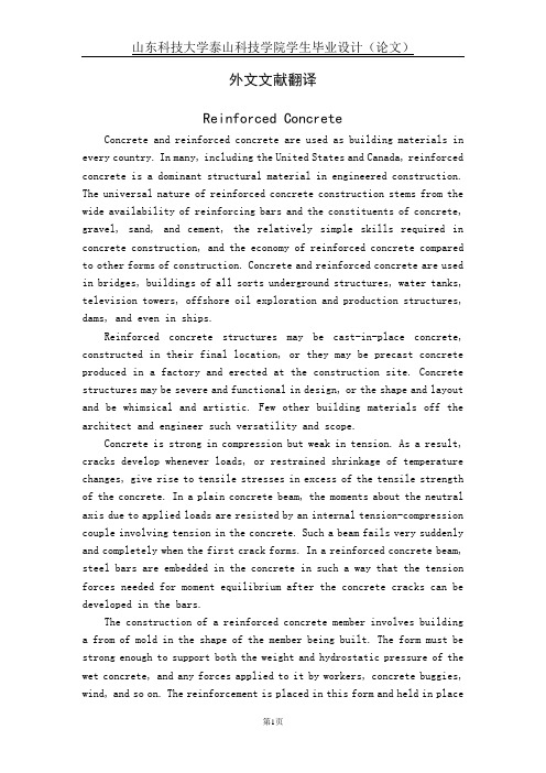
FIG. 1a. Analytical model
FIG. 1b. Free body diagram
Uniform seismic accelerations khg and kvg are assumed in the horizontal and vertical directions respectively in the domain under consideration. As a first step, only planar rupture surfaces have been considered and to keep this assumption valid, wall friction angle δ has been restricted to less than or equal to φ/3 as shown by Terzaghi (1943). In Fig.1b, the freebody diagram of an elemental slice shows the action of different forces. The thickness of the slice is dy, at a depth of y from the top ground surface. The vertical pressure py is acting on the top of the element and (py+ dpy) on the bottom of the element. The reaction px normal to the wall and the shear force pxtan δ are acting on the interface between the retaining wall and the backfill material. The normal force r and the shear force rtan φ act on the sliding surface. The other forces are, the weight dW of the element, the seismic forces dWkh in the horizontal direction and dWkv in the vertical direction. The critical directions of these seismic forces are as shown in Fig.1b. The horizontal slip planes are assumed as principal planes. Resolving all the forces in the vertical and horizontal directions, from the boundary condition py = 0 at y = 0, and ignoring higher order differential terms and upon simplification, the expression for the seismic passive earth pressure at any depth y is obtained as, n px = K 2 + a K