教育一体机TL182-V2.0 板卡规格书
SCT Board V2.0
打开链接文件:当有链接文件的时候这图标才会显示,点击可打开链接的文件
菜 全选:选中全部图形 深圳中电数码显示有限公司
中电数码电子白板应用软件 V2.0
8
单 删除:删除选中图形 复制:复制选中图形 剪切:剪切选中图形 粘贴:粘贴被剪切或复制的图形 置于顶层:将选中的图形置于最顶层 上移一层:将选中的图形上移一层 下移一层:将选中的图形下移一层 置于底层:将选中的图形置于最底层 锁定:将选中的图形锁定,锁定后将不能编辑,可解除锁定编辑 添加到资源库:可以将图形添加到指定的资源库,选中您需要添加到资 源库的对象后选择”组合”按键,点击此菜单会弹出资源保存的对话 框,输入资源名称,点击”确定”即可 打开链接文件:如果图形存在链接,即会出现此菜单,点击即可打开链 接文件 链接管理:点击此菜单,可弹出链接路径的设置框
屏幕键盘:调出屏幕键盘 自定义工具:可实现此白板软件和第三方应用软件的无缝链接,在此处可添加
第三方软件的快捷方式,点击 快捷方式
图标可添加快捷方式,点击
图标可删除
新建页面 新建一个空白的页面
选 变换角度:当选中的图形是多边开的时候,点击此图标可以变换角度
择 旋转图形:把对象任意旋转
图形缩放:放大和缩小对象
字体属性:设置字体的属性
深圳中电数码显示有限公司
中电数码电子白板应用软件 V2.0
10
屏幕键盘:点击调出屏幕键盘
输入文字:点击图标后,在白板处点击时会出现一个文字输入光标
填充颜色:点击选择改变填充颜色
填充
填充类型:设置图形的填充类型 边框线条粗细:边框的粗细可通过滑动条来调节
图形分割:把图形沿分割线分成两份
设置白板为英文点击可弹出菜单选择隐藏还原取可恢更新提示u显示新版软件的更新内容在线升级v在网络连通时升级为最新版本白板注册w关于x帮助y退出z未注册的版本会显示此菜单试用版的软件只能运行30天过期未注册时白板软件将无法使用显示软件版本的相关信息运行软件的帮助文档退出白板应用程序退出程序退出白板应用程序打开文件打开白板格式office文档和其它格式文档
安卓四核TLA18.C V2.1板卡规格书
产品特点
1、采用的 Four CORTEX A7 内核主芯片,主频高达 1.2GHz,GPU 为 mali400X4, 内存 1G,板载 4G 存储空间; 2、采用 Android4.2 操作系统,可支持 APP 扩展; 3、可支持无线鼠标, 4、RJ45 接口可进行有线网络连接; 5、支持 H.264 视频播放; 6、支持 LVDS BYPass HDMI 4K 30P 信号; 7、USB 接口,可连接大容量移动硬盘,同时可连接鼠标与键盘进行操作; 8、支持音乐播放,图片浏览,享受更多家庭娱乐; 9、支持 SD 卡扩展容量 UP to 32G。
VGA 输 入/NC
触摸框 内置电脑
预留 无线 MIC
VG
VGA Audio 输入
RS232
AV1 输入
AV 色 2差 输输 入入
耳 AV
光纤 机 输
输出 输 出
出
TV 输入
USB3. 外置
0
电脑
TECON
A 扩展板
T-VGA-3
深圳泰科晶显有限公司
TLA18.C-规格书
前置 VGA 扩展
VGA 扩展控制(接主板)
深圳泰科晶显有限公司
TECON
TLA18.C-规格书
目录
版本记录.................................................................................................................................... 3 概述............................................................................................................................................ 4
M218控制器

• •
第一章 产品简介-编程软件 产品简介M218控制器的可编程开发软件: M218控制器的可编程开发软件:SoMachine V2.0 控制器的可编程开发软件 SoMachine是一个专业的 高效的,开放的OEM解决方案软件, 是一个专业的, OEM解决方案软件 SoMachine是一个专业的,高效的,开放的OEM解决方案软件,可 以在单个环境中组态和调试整个机器. 以在单个环境中组态和调试整个机器. – HMI控制器 HMI控制器 • HMI控制器 控制器; Magelis XBT GC HMI控制器; • 控制器; XBT GT/GK CANopen HMI 控制器; – 逻辑控制器 • 逻辑控制器; Modicon M218 逻辑控制器; • 逻辑控制器; Modicon M238 逻辑控制器; • 逻辑控制器; Modicon M258 逻辑控制器; – 运动控制器 • LMC058 – 传动控制器 • ATV IMC
技术参数-继电器输出特征 第二章 技术参数-继电器输出特征
输出供电 额定电流值
额定电压 供电范围
24VDC 5V~ 5V~30VDC 2A/通道 2A/通道 4A 0.1Hz 5Hz 否 继电器线圈 20,000,000次 20,000,000次 非屏蔽30m 非屏蔽30m
220VAC 100VAC~ 100VAC~250VAC
电流/ (4通道) 电流/组(4通道) 通道 最大输出频率 防短路 输出类型 机械寿命 电缆长度 最大负载 无负载
技术参数-模拟量输入特征 第二章 技术参数-模拟量输入特征
输入类型 最大输入通道数 输入类型 输入范围 输入阻抗 I/O端子类型 I/O端子类型 采样时间 总输入传输时间 输入误差 输入精度 允许的过载电压 保护类型 极性接反 电缆长度 电缆类型 -10VDC~10VDC 10VDC~ 0~10VDC >1MΩ 可插拔端子 10ms/通道+1扫描周期 10ms/通道+1扫描周期 通道+1 20ms+1扫描周期 20ms+1扫描周期 +1% 12位 12位,包含符号位 +30VDC 输入和内部电路之间的光耦隔离 保护 最大屏蔽电缆3 最大屏蔽电缆3米 屏蔽电缆 电压输入 2 单端输入 0~20mA 4~20mA <250Ω 电流输入
21.5寸电子班牌规格书-触屏版
语言
OSD
简中/英语
附件
电源线
×1
壁挂支架
×1
合格证
×1
说明书
×1
保修卡
×1
第二章
2.
触摸参数
触摸类型
投射式电容屏
触摸点数
10点
触控压力
<10g
透光率
>92%
连接方式
FPC
响应速度
≤10ms
最小识别点大小
5mm×5mm
最小触点移动检测
1mm
抗光性
具有抗光性
寿命
60000小时
R/L 178 (Min.), U/D 178 (Min.)
寿命
50,000 hrs(min.)
可视面积
476.6mm×268.1mm
帧频率
60Hz
电压供应
5V
安卓配置
CPU
RK3288四核1.8GHzCortex-A17
内部缓存容量(RAM)
2GB
内部存储容量(ROM)
8GB
系统版本
Android5.1
RTC实时时钟
支持 Support
系统升级
支持本地SD,USB升级
外设
摄像头
内置200万高清摄像头支持人脸识别
ARM CortexA7
拾音器
内置高音质麦克风
读卡器
内置IC/ID双频读卡器
电源
电压
100V~240V,50-60Hz
额定功耗
≤35W
待机功率
≤1W
环境
工作温度
0℃~50℃
储藏温度
-20℃~60℃
输入接口
广勤电子负载KP182说明书中文版2017

菜单和功能
A.SYS(T)
系统设置
1.ADD(R)
设置通讯地址,设置范围 1-250。
3.H(A)载次池电LF低输后压输低于出电出终于电止压放再电压电次会压终低小时止于电,幅终上 仍压止后升然电, 以,半压设电半电。定电池流流放的放放电电电量电电。流功仍电能的有池一少即测在半部试值分放时继没电,续到有一拉电放般完池载在,,电放关直压电到第闭电拉一到
ON 打开半电流放电功能。
OFF
关闭半电流放电功能。
KP182系列产品具有的特殊功能和优点:
●具有 CC、CV、CW、CR 四种基本负载模式; ●输入正负反接保护并报警; ●优化的散热结构实现高功率密度; ●数字化的操控方式,精度高稳定性好; ●具备过电压,过电流,过功率,过温度保护; ●电压远端测量的功能; ● 试功 带 自动测 能, 有外部 I/O 触发信号、PASS、FAIL 示指 信号; ●10KHz 动态测试功能; ●电池容量测试功能; ●电池内阻测试功能; ●过流保护点/保护时间测试功能; ●风扇 PWM 温控; ●供电 110VAC/220VAC 切换使用; ●RS485、232 通讯接口,MODBUS 协议(仅 4) KP18 ; ●具有多台负载联机同步操作功能(仅 4) KP18 ; ●功能强大界面友好的上位机软件支持(仅 4) KP18 ;
进入菜单设置 Shift + Mode(Battery):
调用设定值第 组 Shift + (Recall):
AM182_产品手册_v1.0
℃
Tstg
-40
+85
℃
发射机
发射频率
f
24.000 24.125 24.250
GHz
输出功率(EIRP)
Pout
12
接收机
dBm
IF输出电压 I/Q幅度平衡 I/Q相位平衡
UIF
-200
+200
mV
∆UIF
3
dB
∆φ
80
90
100
º
天线
水平方向-3dB波束宽度
WE
80
º
垂直方向-3dB波束宽度
WH
34
º
垂直方向旁瓣抵制比
DH
13
dB
注:在操作、组装、测试雷达收发器时,须注意静电防护,静电易造成雷达收发器损伤。
v1.0
第 2 页 2018-03
产品尺寸
AM182
产品接口
引脚 序号
1 2 3 4 5
AM182-I
引脚名称
说明
IFI
中频同相信号I
IFQ
中频正交信号Q
GND
地
VCC
电源
NC
空
AM182-R
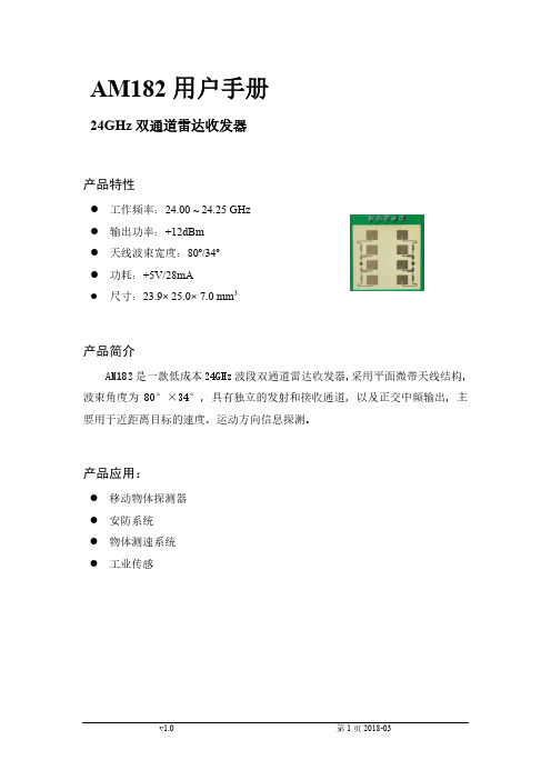
产品应用:
移动物体探测器 安防系统 物体测速系统 工业传感
v1.0
第 1 页 2018-03
产品拓扑
TX
RX
I
90°
Q
AM182
产品参数
参数名称
符号
最小
数值 典型
最大
单位
工作条件
工作电压 工作电流 工作温度 存储温度
Vcc
4.75
5.0
5.25
九龙坡区华岩小学班班通系统参数配置
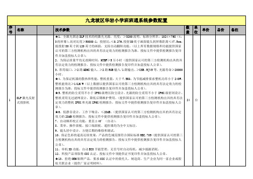
7.使用环境:工作温度:温度:-5℃~40℃,相对湿度:30%~80%;存放温度:温度:-20℃~55℃,相对湿度:10%~90%。
24
台
2
电子白板一体机
(一)整体设计要求:
白板一体机模块:
1.白板一体机模块设计要求:整机采用一体化壁挂式安装,红外电子白板、智能中控、电脑主机、功放、音箱、高拍仪/展台等功能模块,集成在整个框架内;无外露连接线,非单侧或双侧箱体连接式结构,整机安装无需白板触摸线、展台数据线、中控等布线施工;一体化的设计使得各模块间有更好的兼容性。
2.产品尺寸:外观尺寸≥90英寸,显示比例:4:3。
3.板体材质:面板采用纳米烤漆涂层钢板,背板采用铝蜂窝板,边框采用铝合金材料,坚固耐用,不易变形。
4.内置音箱:功率≥30W,喇叭口朝向正面。(提供国家认可的第三方检测机构出具的具有法定效力的检测报告,复印件加盖投标人鲜章)
★5.一键锁屏:前置面板有锁定键,按下后锁住屏幕触摸和按键面板按键和展台锁,通过刷卡或组合按键解锁,防止课间学生操作白板一体机。(提供国家认可的第三方检测机构出具的具有法定效力的检测报告,复印件加盖投标人鲜章)
13.为保证产品质量要求提供平均无故障时间(MTBF)不低于100000小时。(提供国家认可的第三方检测机构出具的具有法定效力的检测报告为准,投标文件中提供检测报告复印件并加盖投标人公章)
24
套
红外白板模块
一体机中内嵌红外白板模块
1.触摸技术:红外线感应技术;触摸有效识别高度低于3mm,书写延迟<80ms,光标速度180点/秒,触摸屏单点触摸响应时间≦7ms,定位精度±0.1mm。
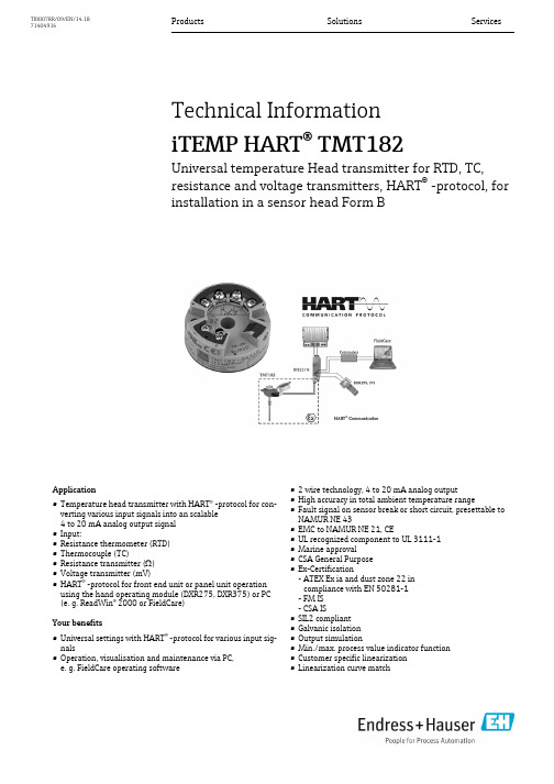
TMT182
10 K 10 K 10 K
·接 线模 式 :2线 ,3线 ,4线连 接 ·2线 连 接 时 , 通 过 软 件 对 电 缆 电阻 可 进行 补偿( 0~30Ω) ·3线 和4线 连 接 时 , 传 感器 电 缆电 阻ma x. 2 0Ω / 每 芯 ·传 感器 电流 :≤0.2 mA
电阻组态 热电偶(TC)
输入
测 量变 量 测 量范 围 输 入类 型
温 度(温 度线 性 传 输),电 阻和 电 压 变送器测量 范围 的变 化取决于传感器 连接模式 和输入信号
型号
Pt100 Pt500 Pt1000 符合IEC 751
测量范围
最小测量范围
-2 00~8 5 0℃ -2 00~2 5 0℃ -2 00~2 5 0℃
特点
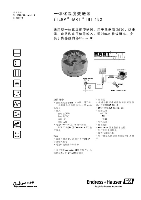
·通 用可 组态型,适 用于 各种HAR T 协议 输入 信号 ·通 过PC进行 操 作 和 维 护
·高 精度 ·传 感器损 坏或 短路故 障信 号可预 设, 符合NAMUR NE 43 ·E M C符 合N A M UR NE 2 1,C E ·防 爆认 证
—A T EX —F M —- C SA ·电 气隔 离 ·输 出模 拟 ·m i n. / m ax.测量 值指 示 功 能 ·用 户自 定义 线性化 ·线 性化 曲线 匹配 ·用 户自 定义测量范 围设 定和扩展设 定
技术 资料 TI 078R/09/zh/v1.0 51 0 0 20 7 3
一体化温度变送器 iTEMP HART TMT 182
通 用 型 一 体 化 温度 变 送器 , 用 于 热 电 阻( RT D )、热 电 偶 、 电 阻 和 电 压信 号 输入 , 通 过H A R T协 议组 态 ,安 装 于 传 感 器 内 部( F o r m B )
SCT Board2.0(电子白板)教学用一体机使用详细教程
1
常用教学工具介绍——系统菜单、书写、字体、擦除、撤销、 重绘、页面移动、新建界面、翻页、绘制图形、填充、直线 工具、 对象选择
2
辅助教学工具介绍——屏幕工具、导入资源、背景、 资源库、结合PPT使用、保存
『软件工作模式』
『软件功能介绍』
『软件功能介绍』
『软件功能介绍』
『软件功能介绍』
『软件功能介绍』
『软件功能介绍』
『软件功能介绍』
『软件功能介绍』
『软件功能介绍』
『软件功能介绍』
『软件功能介绍』
『软件功能介绍』
『软件功能介绍』
『软件功能介绍』
『资源库介绍』
『在线资源库』
*提供自主品牌的教育资源网站,可为用户终身免费提供教学资源浏览和下载功能, 并保证资源定期更新和升级;
*教育资源网站的教学素材库覆盖国内包括人教版、北师大版、苏教版、华师大 版等至少8种或以上主流的小学到高中的教材版本
多媒体电视互动一体机
使用培训
目录
硬件及操作规范
软件功能介绍
『硬件操作规范』
1
开关机顺序— 开机:先开显示器,后开电脑主机; 关机:先关主机后关显示器
2
按键、端口的认识——(附图)
3
故障排查
『按键功能介绍』
1
2 电 脑 主 机 开 关
示图
电 源 指 示 灯
显 示 器 开 关
信 号 源
பைடு நூலகம்端口介绍』
*教育资源网站提供的在线实验系统,要求每个实验至少包括实验目的、实验器材、 实验步骤、注意事项等栏目
再见
RS232
VGA
电 源 开 关
电 源 线 接 口
音 频 输 出 路
M185-V2.0_八核_技术规格书
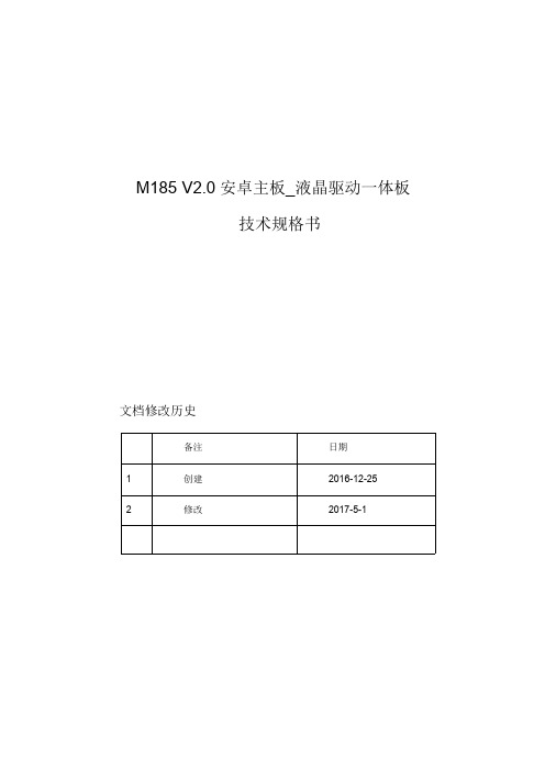
M185V2.0安卓主板_液晶驱动一体板技术规格书文档修改历史备注日期1创建2016-12-252修改2017-5-1M185是一款基于全志A83T主芯片开发的多媒体液晶驱动一体板。
本款主板搭载1G DDR3+8G eMMC,可以支持LVDS点屏和HDMI高清输出。
其主控IC采用台积电28nm HPC制造工艺,基于ARM Cortex-A7架构,八个核心,主频最高可达2GHz。
采用全志新一代SmartColor技术,有助于在高分辨率下显示出色的图像质量,为您的整机提供赏心悦目的视觉效果。
基本硬件规格:CPU全志A83T,八核ARM Cortex A72.0GHzGPU PowerVR SGX544内存DDR31G(Up to2G)内置存储容量EMMC8GB/16G/32G可选(标贴8GB)显示屏接口LVDS接口(单路,6位双路,8位双路)。
支持最大分辨率1920×1080,支持7"-100"显示屏屏电压选择支持3.3V/5V/12V可选网络RJ45标准接口,百兆以太网接口。
具备蓝牙+wifi模块,支持Wi-Fi802.11b/g/n协议。
支持蓝牙4.0协议。
可外挂3G\4G小板,支持3G数据/4G数据功能,支持WCDMA、EVDO、CDMA、GSM,2G/3G全频段支持850/900/1800/1900MHz/2100MHz(3G\4G小板请联系我司采购)屏幕旋转支持0度,90度,180度,270度手动旋转实时时钟内置实时时钟供电电池、支持定时开关机接口设备支持USB摄像头支持HDMI1.4输出1080P6个USB HOST、2个板载、4个外接扩展3个TTL,其中2个可兼容RS232接口。
支持外接串口设备模块(扩展传感器或一维码,二维码扫描,打印机,刷卡器模块等等)TF卡扩展,最大支持64GB1路标准I2C接口支持耳机输出,内置功放,支持2W*28欧喇叭音频输入支持MIC,1个麦克风接口锂电池接口支持单节锂电池充放电,系统掉电保护,防止重要数据丢失(在V1.2版本基础上增加了该功能)触摸屏支持红外、电阻、电容触摸屏电源输入:DC12V或DC12V5VSTB(开关电源)基本软件规格:操作系统Google Android4.4.4系统语言支持多国语言视频格式Support Video playback up to1080P@60fpsSupport Multi-Format video playback,including Mpeg1、Mpeg2、Mpeg4SP/ASP GMC、H.263including sorenson spark、H.264BP/MP/HP、VP8、WMV9/VC1、JPEG/MJPEG、etcHEVC/H.2651080P@30fps音频格式支持MP3,WMA,MP2,OGG,AAC,M4A,MA4,FLAC,APE,3GP,WAV格式音频播放,支持歌曲列表功能图片浏览支持JPG、BMP、PNG、GIF等各种图片格式浏览并支持旋转/幻灯片播放,最高支持到4096*4096分辨率文书处理WORD,EXCEL,POWERPOINT,PDF,TXT输入法标准Andriod键盘,可选第三方输入法(中文、韩文、日文等)扩展性Google市场多达2万多种优秀软件免费下载系统管理文件管理器原生态Android系统,开放root权限,可进行产品定制开发定时开关机支持OTA远程升级(需定制)3主要接口3.1接口分布图3.2主要接口介绍◆JP9(4PIN/2.0)电源输入扩展口◆◆JP4(6PIN/2.0)背光逆变器控制序号定义属性描述112V 电源输出背光电源输出,+12V 序号定义属性描述112V 电源输入+12V 电源输入212V 电源输入+12V 电源输入3GND 地线地线4GND 地线地线55VSB 输入待机电源,+5V 6STB 输出待机电源控制23BL_EN输出背光板开关控制脚4BL_ADJ输出背光板亮度控制脚5GND地线地线6◆JP21(6PIN/2.0)按键接口◆JP13(6PIN/2.0)CTP/I2C电容触摸屏接口◆JP1(2X15PIN/2.0)LVDS信号输出◆JP6(2X3PIN/2.0)液晶屏屏压选择接口◆JP12(4PIN/2.0)扬声器输出11RXO2-输出Pixel2Negative Data (Odd)12RXO2+输出Pixel2Positive Data (Odd)13GND 地线电源地1415RXOC-输出Negative Sampling Clock (Odd)16RXOC+输出Positive Sampling Clock (Odd)17RXO3-输出Pixel3Negative Data (Odd)18RXO3+输出Pixel3Positive Data (Odd)19RXE0-输出Pixel0Negative Data (Even )20RXE0+输出Pixel0Positive Data (Even )21RXE1-输出Pixel1Negative Data (Even )21RXE1+输出Pixel1Positive Data (Even )23RXE2-输出Pixel2Negative Data (Even )24RXE2+输出Pixel2Positive Data(Even )25GND 地线电源地2627RXEC-输出Negative Sampling Clock (Even )28RXEC+输出Positive Sampling Clock (Even )29RXE3-输出Pixel3Negative Data (Even )30RXE3+输出Pixel3Positive Data (Even )◆JP18(4PIN/2.0)UART4串口◆J23(4PIN/2.0)UART2串口◆J17(4PIN/2.0)UART1串口◆J9(4PIN/2.0)USB3扩展接口◆J11(4PIN/2.0)USB4扩展接口◆J7(4PIN/2.0)USB6扩展接口◆J8(4PIN/2.0)USB7扩展接口◆JP22(5PIN/2.0)遥控接收、工作指示灯◆JP3(2PIN/2.0)MIC麦克风接口◆J4 3.5mm耳机孔,音频输出◆J5Micro SD卡座◆HCON1HDMI信号输出,最高支持1080P◆U210RJ45,100M网口◆SW3UBOOT按键,配合系统升级使用◆JD14USB0_OTG接口,可用于系统升级或者调试◆JD13USB2-HOST接口,可接外部USB设备ANT1WIFI天线外接座子2.4G BT4.04寸4.1板卡尺寸PCB长:123.9mm PCB宽:87.8mm板总体高度约16mm,详细结构图请咨询业务员。
STM6M182VGABNC 工业液晶监视器驱动板卡规格书

地 地 HDMI 5V
地 地
6/14
20
I2CSDA
CON3(6PIN/2.0) INVERTER 接口
脚序号
定义
1
GND
2
GND
3
ADJ
4
BL_ON
5
12V
6
12V
CON4(4PIN/2.0) 烧录接口
脚序号
定义
1
NC
2
GND
3
RXD
0
22
RXE1+
0
23
RXE2-
0
24
RXE2+
0
25
GND
Ground
26
GND
Ground
27
RXEC-
0
28
RXEC+
0
TEL:0755-61566082 FAX:0755-61566083
工业监视器驱动板规格书 LVDS ODD 0 - Signal LVDS ODD 0 + Signal LVDS ODD 1 - Signal LVDS ODD 1 + Signal LVDS ODD 2 - Signal LVDS ODD 2 + Signal
VGA
15 针 D-Sub
输入
S-Video
接
CVBS
口 YPbPr
音频
输出
PANEL 接口 音频
输入电源
可选
BNC 端子
BNC 端子 CVBS, YPbPr 共用一路音频输入
PC 单独一路音频输入 LVDS30/34/40 Pin/2.0 直式金针插座
HART TMT182多功能温度头传感器说明书
Products SolutionsServicesTechnical Information iTEMP HART ® TMT182Universal temperature Head transmitter for RTD, TC, resistance and voltage transmitters, HART ® -protocol, for installation in a sensor head Form BApplication•Temperature head transmitter with HART ® -protocol for con-verting various input signals into an scalable 4 to 20 mA analog output signal •Input:•Resistance thermometer (RTD)•Thermocouple (TC)•Resistance transmitter ( )•Voltage transmitter (mV)•HART ® -protocol for front end unit or panel unit operation using the hand operating module (DXR275, DXR375) or PC (e. g. ReadWin ® 2000 or FieldCare)Your benefits•Universal settings with HART ® -protocol for various input sig-nals•Operation, visualisation and maintenance via PC, e. g. FieldCare operating software •2 wire technology, 4 to 20 mA analog output•High accuracy in total ambient temperature range•Fault signal on sensor break or short circuit, presettable to NAMUR NE 43•EMC to NAMUR NE 21, CE•UL recognized component to UL 3111-1 •Marine approval •CSA General Purpose •Ex-Certification- ATEX Ex ia and dust zone 22 in compliance with EN 50281-1- FM IS - CSA IS•SIL2 compliant •Galvanic isolation •Output simulation•Min./max. process value indicator function •Customer specific linearization •Linearization curve matchTI00078R/09/EN/14.1871404916TMT1822Endress+HauserFunction and system designMeasuring principle Electronic monitoring and conversion of input signals in industrial temperature measurement.Measuring systemThe iTEMP HART ® TMT182 temperature head transmitter is a 2-wire transmitter with analog output. It has measurement input for resistance thermometers (RTD) in 2-, 3- or 4-wire connection,thermocouples and voltage transmitters. Setting up of the TMT182 is done using the HART ® -Protocol with hand operating module (DXR275, DXR375) or PC (e.g. configuration software ReadWin ® 2000 or FieldCare).InputMeasured variable Temperature (temperature linear transmission behaviour), resistance and voltageMeasuring rangeDepending upon the sensor connection and input signal. The transmitter evaluates a number of different measurement ranges.Type of inputResistance thermometer (RTD)TypeMeasurement rangesMin. measurement rangePt100Pt500Pt1000acc. to IEC 60751 (α = 0.00385)Pt100to JIS C1604-81 (α = 0.003916)-200 to 850 °C (-328 to1562 °F)-200 to 250 °C (-328 to 482 °F)-200 to 250 °C (-238 to 482 °F)-200 to 649 °C (-328 to 1200 °F)10 K (18 °F)10 K (18 °F)10 K (18 °F)10 K (18 °F)Ni100Ni500Ni1000acc. to DIN 43760 (α = 0.006180)-60 to 250 °C (-76 to 482 °F)-60 to 150 °C (-76 to 302 °F)-60 to 150 °C (-76 to 302 °F)10 K (18 °F)10 K (18 °F)10 K (18 °F)•Connection type: 2-, 3- or 4-wire connection•Software compensation of cable resistance possible in the 2 wire system (0 to 30 Ω)•Sensor cable resistance max. 20 Ω per cable in the 3 and 4 wire system •Sensor current: ≤ 0.2 mA•Corrosion detection as per NAMUR NE 89 for Pt100 4-wire connection (optional for 'A dvanced Diagnostic' version, see 'P roduct structure'). If corrosion detection is active, the response time is 2 s.Resistance transmitter Resistance Ω10 to 400 Ω10 to 2000 Ω10 Ω100 ΩThermocouple (TC)B (PtRh30-PtRh6)C (W5Re-W26Re)1)D (W3Re-W25Re)1E (NiCr-CuNi)J (Fe-CuNi)K (NiCr-Ni)L (Fe-CuNi)2)N (NiCrSi-NiSi)R (PtRh13-Pt)S (PtRh10-Pt)T (Cu-CuNi)U (Cu-CuNi)2acc. to IEC 584 Part 10 to +1820 °C (32 to 3308 °F)0 to +2320 °C (32 to 4208 °F)0 to +2495 °C (32 to 4523 °F)-270 to +1000 °C (-454 to 1832 °F)-210 to +1200 °C (-346 to 2192 °F)-270 to +1372 °C (-454 to 2501 °F)-200 to +900 °C (-328 to 1652 °F)-270 to +1300 °C (-454 to 2372 °F)-50 to +1768 °C (-58 to 3214 °F)-50 to +1768 °C (-58 to 3214 °F)-270 to +400 °C (-454 to 752 °F)-200 to +600 °C (-328 to 1112 °F)500 K (900 °F)500 K (900 °F)500 K (900 °F) 50 K (90 °F) 50 K (90 °F) 50 K (90 °F) 50 K (90 °F) 50 K (90 °F)500 K (900 °F)500 K (900 °F)50 K (90 °F)50 K (90 °F)•Cold junction: internal (Pt100)•Cold junction accuracy: ± 1 KVoltage transmitters Millivolt transmitter -10 to 75 mV 5 mV1) acc. to ASTM E9882) acc. to DIN 43710TMT182Endress+Hauser 3OutputOutput signal Analog 4 to 20 mA, 20 to 4 mASignal on alarm•Underranging: linear drop to 3.8 mA •Overranging: linear rise to 20.5 mA•Sensor break; sensor short-circuit (not for thermocouples TC): ≤ 3.6 mA or ≥ 21.0 mALoadmax. (V Power supply - 11.5 V) / 0.022 A (Current output)Linearization/transmission behaviour Temperature linear, resistance linear, voltage linearFilter1st order digital filter: 0 to 100 s Galvanic isolation U = 2 kV AC (input/output)Min. current consumption ≤ 3.5 mA Current limit ≤ 23 mASwitch on delay4 s (during power up I a = 3.8 mA)Power supplyElectrical connectionHead transmitter terminal connectionsFor the unit operation via HART ® protocol (terminals 1 and 2) a minimum load resistance of 250 Ω is necessary in the signal circuit!Supply voltage U b = 11.5 to 35 V, polarity protectionUndervoltage detectionOptional for 'A dvanced Diagnostic' version.If the supply voltage is not sufficient to output the output signal corresponding to the measuredtemperature, a signal on alarm ≤ 3.6 mA is generated. After approx. 2 to 3 s, the system makes another attempt to output the signal corresponding to the temperature.Guaranteed values for setting "high alarm" (≥ 21 mA):•Standard model: > 21.5 mA•Advanced diagnostic model: ≥ 22.5 mATMT1824Endress+HauserResidual rippleAllowable ripple U ss ≤ 3 V at U b ≥ 13 V, f max. = 1 kHzPerformance characteristicsResponse time 1 s (TC), 1.5 s (RTD)Reference operating conditionsCalibration temperature: +25 °C (77 °F) ± 5 K (9 °F)Maximum measured errorInfluence of supply voltage≤ ± 0.01%/V deviation from 24 VPercentages refer to the full scale value.Influence of ambienttemperature (temperature drift)Total temperature drift = input temperature drift + output temperature driftThe accuracy data are typical values and correspond to a standard deviation of ± 3σ (normal distribution), i.e. 99.8% of all the measured values achieve the given values or better values.TypeMeasurement accuracy 1Resistancethermometer RTDPt100, Ni100Pt500, Ni500Pt1000, Ni10000.2 K or 0.08%0.5 K or 0.20%0.3 K or 0.12%Thermocouple TCK, J, T, E, L, U N, C, D R, S Btyp. 0.5 K or 0.08%typ. 1.0 K or 0.08%typ. 1.4 K or 0.08%typ. 2.0 K or 0.08%Measurement rangeMeasurement accuracy 1)1) % is related to the adjusted measurement range. The value to be applied is the greater.Resistance transmitter (Ω)10 to 400 Ω10 to 2000 Ω± 0.1 Ω or 0.08%± 1.5 Ω or 0.12%Voltage transmitters (mV)-10 to 75 mV± 20 μV or 0.08%Physical input range of the sensors 10 to 400 ΩPolynom RTD, Pt100, Ni10010 to 2000 ΩPt500, Pt1000, Ni1000-10 to 75 mV Thermocouple type: C, D, E, J, K, L, N, U -10 to 35 mVThermocouple type: B, R, S, TEffect on the accuracy when ambient temperature changes by 1 K (1.8 °F):Input 10 to 400 Ωtyp. 0.0015% of measured value, min. 4 m ΩInput 10 to 2000 Ωtyp. 0.0015% of measured value, min. 20 m ΩInput -10 to 75 mV typ. 0.005% of measured value, min. 1.2 μV Input -10 to 35 mV typ. 0.005% of measured value, min. 0.6 μV Output 4 to 20 mAtyp. 0.005% of spanTMT182Endress+Hauser 5Example for calculating measured error for ambient temperature drift:Input temperature drift ∆T = 10 K (18 °F), Pt100, measuring range 0 to 100 °C (32 to 212 °F)Maximum process temperature: 100 °C (212 °F)Measured resistance value: 138.5 Ω (IEC 60751) at maximum process temperature Typical temperature drift in Ω: (0.0015% of 138.5 Ω) * 10 = 0.02078 ΩConversion to Kelvin: 0.02078 Ω / 0.385 Ω/K = 0.05 K (0.09 °F)Influence of load± 0.02%/100 ΩValues refer to the full scale valueLong-term stability≤ 0.1 K/year or ≤ 0.05%/yearValues under reference operating conditions. % refer to the set span. The highest value is valid.Influence of cold junctionPt100 DIN IEC 60751 Cl. B (internal cold junction with thermocouples TC)Installation conditionsInstallation instructions•Installation angle:no limit•Installation area:Terminal head accord. to DIN 43 729 Form B; TAF10 field housingEnvironment conditionsAmbient temperature limits-40 to +85 °C (-40 to 185 °F) for Ex-area, see Ex-certificateStorage temperature -40 to +100 °C (-40 to 212 °F)Climate class According to IEC 60 654-1, class C Condensation PermittedDegree of protection IP 00, IP 66 installedShock and vibration resistance4g / 2 to 150 Hz as per IEC 60 068-2-6Typical sensitivity of resistance thermometers:Pt: 0.00385 * R nominal /KNi: 0.00617 * R nominal /KExample Pt100: 0.00385 x 100 Ω/K = 0.385 Ω/KTypical sensitivity of thermocouples:B: 10 μV/K C: 20 μV/K D: 20 μV/K E: 75 μV/K J: 55 μV/K K: 40 μV/K L: 55 μV/KN: 35 μV/KR: 12 μV/KS: 12 μV/KT: 50 μV/KU: 60 μV/KTMT1826Endress+HauserElectromagnetic compatibility (EMC)CE conformityEMC to all relevant requirements of the IEC/EN 61326 - series and NAMUR Recommendation EMC (NE21). For details, refer to the Declaration of Conformity.Maximum fluctuations during EMC- tests: < 1% of measuring span.Interference immunity to IEC/EN 61326 - series, requirements for industrial areas Interference emission to IEC/EN 61326 - series, electrical equipment Class BMechanical constructionDesign, dimensionsDimensions of the head transmitter in mm (in)Weight approx. 40 g (1.4 oz)Material•Housing: PC •Potting: PURTerminals•Cable up to max. 1.75 mm 2 (secure screws)•or 1.5 mm 2 with wire end ferrules•eyelets for easy connection of a HART ®-handheld terminal with alligator clipsHuman interfaceDisplay elementsNo display elements are present directly on the temperature transmitter.The measured value display can be called up using the ReadWin ® 2000 or FieldCare PC software.Operating elementsAt the temperature transmitter no operating elements are available directly. The temperaturetransmitter will be configured by remote operation with the PC software ReadWin ® 2000 or FieldCare.Remote operationConfigurationHand operating module DXR275, DXR375 or PC with Commubox FXA191/FXA195 and operating software (ReadWin ® 2000 or FieldCare).InterfacePC interface Commubox FXA191 (RS232) or FXA195 (USB)Configurable parametersSensor type and connection type, engineering units (°C/°F), measurement range, internal/external cold junction, compensation of wire resistance with 2-wire connection, failure mode, output signal (4 to 20/20 to 4 mA), digital filter (damping), offset, TAG + descriptor (8 + 16 characters), output simulation, customer specific linearization, min./max. process value indicator functionTMT182Endress+Hauser 7Certificates and approvalsCE-MarkThe device meets the legal requirements of the EC directives. Endress+Hauser confirms that the device has been successfully tested by applying the CE mark.Hazardous area approvalsFor further details on the available Ex versions (ATEX, CSA, FM, etc.), please contact your nearest Endress+Hauser sales organisation. All relevant data for hazardous areas can be found in separate Ex documentation. If required, please request copies from us or your Endress+Hauser sales organisation.Marine approvalFor further details on the available "Type Approval Certificiates" (DNVGL, BV, etc.), please contact your nearest Endress+Hauser sales organisation. All relevant data for marine approval can be found in separate "Type Approval Certificiates". If required, please request copies from us or your Endress+Hauser sales organisation.Other standards and guidelines•IEC 60529:Degree of protection provided by housing (IP-Code)•IEC 61010:Safety requirements for electrical measurement, control and laboratory use.•IEC 61326:Electromagnetic compatibility (EMC requirements)•NAMURStandards working group for measurement and control technology in the chemical industry. (www.namur.de)UL approval UL recognized component (see /database, search for Keyword "E225237")CSA GPCSA General PurposeExamination certificateIn compliance with WELMEC 8.8, valid only for the SIL-Mode: "Guide on the General andAdministrative Aspects of the Voluntary System of Modular Evaluation of Measuring Instruments.Ordering informationDetailed ordering information is available from the following sources:•In the Product Configurator on the Endress+Hauser website: -> Click "Corporate" -> Select your country -> Click "Products" -> Select the product using the filters and search field -> Open product page -> The "Configure" button to the right of the product image opens the Product Configurator.•From your Endress+Hauser Sales Center: Product Configurator - the tool for individual product configuration •Up-to-the configuration•Depending on the device: Direct input of measuring point-specific information such as measuring range or operating language •Automatic verification of exclusion criteria•Automatic creation of the order code and its breakdown in PDF or Excel output format •Ability to order directly in the Endress+Hauser Online ShopTMT182Accessories•Commubox FXA191 (RS232) or FXA195 (USB)Order code: FXA191-... or FXA195-...•PC-operating software: ReadWin ® 2000 or FieldCareReadWin ® 2000 can be downloaded free of charge from the internet from the following address: /readwin•Hand operating module ’HART ® Communicator DXR375’Order code: DXR375-...•DIN rail clip according to IEC 60715 (TH35) for head transmitter mounting Order code: 51000856•Field housing TAF10 for Endress+Hauser head transmitter, aluminum, IP 66,dimensions W x H x D: 100 x 100 x 60 mm (3.94" x 3.94" x 2.36")Order code: TAF10-...Documentation•Operating short manual iTEMP HART ® TMT182 (KA142R/09/a3)•Additional documentation for use in explosion-hazardous areas:ATEX II1G: XA006R/09/a3ATEX II3G: XA011R/09/a3ATEX II3D: XA027R/09/a3•Operating short manual TAF10 Field housing (KA093R/09/a2)•SIL: Functional safety manual TMT182 (SD006R/09/en)。
TLP182_datasheet_en_20170511

6. Absolute Maximum Ratings (Note) (Unless otherwise specified, Ta = 25 )
Characteristics LED R.M.S. forward current Input forward current derating Input forward current (pulsed) Input power dissipation Input power dissipation derating Junction temperature Detector Collector-emitter voltage Emitter-collector voltage Collector current Collector power dissipation Collector power dissipation derating Junction temperature Common Operating temperature Storage temperature Lead soldering temperature Total power dissipation Total power dissipation derating Isolation voltage (Ta ≥ 25 ) AC, 60 s, R.H. ≤ 60 % (10 s) (Ta ≥ 25 ) (Ta ≥ 90 ) (Ta ≥ 90 ) Symbol IF(RMS) ∆IF/∆Ta IFP PD ∆PD/∆Ta Tj VCEO VECO IC PC ∆PC/∆Ta Tj Topr Tstg Tsol PT ∆PT/∆Ta BVS (Note 2) (Note 1) Note Rating ±50 -1.5 ±1 100 -2.9 125 80 7 50 150 -1.5 125 -55 to 125 -55 to 125 260 200 -2.0 3750 Unit mA mA/ A mW mW/ V V mA mW mW/ mW mW/ Vrms
E18系列产品规格书说明书
E18系列产品规格书CC25302.4GHz ZigBee3.0无线模块目录第一章产品概述 (3)1.1产品简介 (3)1.2特点功能 (4)1.3应用场景 (5)第二章规格参数 (6)2.1射频参数 (6)2.2电气参数 (6)2.3硬件参数 (6)2.4网络系统参数 (7)第三章机械尺寸与引脚定义 (8)第四章硬件设计 (11)第五章软件设计 (11)第六章常见问题 (13)6.1传输距离不理想 (13)6.2模块易损坏 (13)6.3误码率太高 (13)第七章焊接作业指导 (7)7.1回流焊温度 (7)7.2回流焊曲线图 (7)第八章相关型号 (8)第九章天线指南 (8)第十章产品包装图 (8)修订历史 (9)关于我们 (9)第一章产品概述1.1产品简介E18系列是亿佰特设计生产的2.4GHz频段的ZigBee通信协议转串口无线模块,贴片型,PCB板载天线或IPEX-1接口,引脚间距1.27mm,出厂自带自组网固件,到手即用,适用于多种应用场景(尤其智能家居)。
E18系列模块采用美国德州仪器公司原装进口CC2530射频芯片,芯片内部集成了8051单片机及无线收发器,部分模块型号内置PA功率放大器增加通信距离。
出厂自带固件基于ZigBee3.0协议实现的串口数据透传,支持ZigBee3.0协议下各种指令命令。
经实测,对市面上大多数ZigBee3.0产品有着非常良好的兼容性。
1.2ZigBee 3.0优势E18系列模块固件基于Z-Stack3.0.2协议栈(ZigBee 3.0),该版本为CC2530/CC2538系列芯片最优协议栈,因此我司也此基础上做了许多优化,确保系统长期稳定运行。
ZigBee3.0与早前版本的应用方式区别:1.组网方式发生变化:ZigBee 3.0取缔了一上电就组网的方式,而是根据实际需要进行组网。
任何设备在出厂状态下是无网络状态,协调器需要运行“formation”(调用bdb_StartCommissioning(BDB_COMMISSIONING_MODE_NWK_FORMATION))来新建网络,然后再运行"Steering"(调用bdb_StartCommissioning(BDB_COMMISSIONING_MODE_NWK_STEERING))打开网络,打开网络默认时间180秒,可通过广播"ZDP_MgmtPermitJoinReq"的方式将打开网络提前关闭。
欧洲电子产品有限公司 182型号电容器说明书
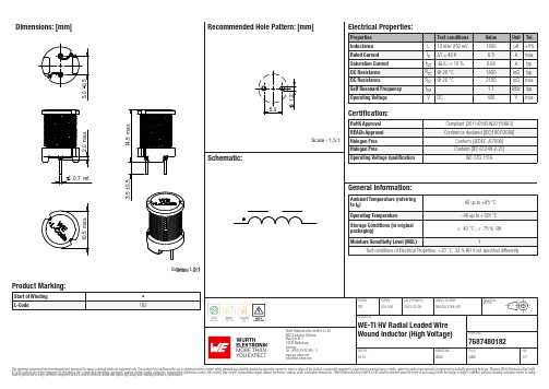
Dimensions: [mm]Scale - 2:1Scale - 1,5:176********768748018276874801827687480182T e m p e r a t u r eT T T 7687480182Cautions and Warnings:The following conditions apply to all goods within the product series of WE-TI-HV ofWürth Elektronik eiSos GmbH & Co. KG:General:•This electronic component is designed and manufactured for use in general electronic equipment.•Würth Elektronik must be asked for written approval (following the PPAP procedure) before incorporating the components into any equipment in fields such as military, aerospace, aviation, nuclear control, submarine, transportation (automotive control, train control, ship control), transportation signal, disaster prevention, medical, public information network, etc. where higher safety and reliability are especially required and/or if there is the possibility of direct damage or human injury.•Electronic components that will be used in safety-critical or high-reliability applications, should be pre-evaluated by the customer. •The component is designed and manufactured to be used within the datasheet specified values. If the usage and operation conditions specified in the datasheet are not met, the wire insulation may be damaged or dissolved.•Do not drop or impact the components, the component may be damaged.•Würth Elektronik products are qualified according to international standards, which are listed in each product reliability report. Würth Elektronik does not warrant any customer qualified product characteristics beyond Würth Elektroniks’ specifications, for its validity and sustainability over time.•The responsibility for the applicability of the customer specific products and use in a particular customer design is always within the authority of the customer. All technical specifications for standard products also apply to customer specific products.Product specific:Soldering:•The solder profile must comply with the technical product specifications. All other profiles will void the warranty.•All other soldering methods are at the customers’ own risk.Cleaning and Washing:•Washing agents used during the production to clean the customer application might damage or change the characteristics of the wire insulation, marking or plating. Washing agents may have a negative effect on the long-term functionality of the product. Potting:•If the product is potted in the customer application, the potting material might shrink or expand during and after hardening. Shrinking could lead to an incomplete seal, allowing contaminants into the core. Expansion could damage the component. We recommend a manual inspection after potting to avoid these effects.Storage Conditions:• A storage of Würth Elektronik products for longer than 12 months is not recommended. Within other effects, the terminals may suffer degradation, resulting in bad solderability. Therefore, all products shall be used within the period of 12 months based on the day of shipment.•Do not expose the components to direct sunlight.•The storage conditions in the original packaging are defined according to DIN EN 61760-2.•The storage conditions stated in the original packaging apply to the storage time and not to the transportation time of the components. Packaging:•The packaging specifications apply only to purchase orders comprising whole packaging units. If the ordered quantity exceeds or is lower than the specified packaging unit, packaging in accordance with the packaging specifications cannot be ensured. Handling:•Violation of the technical product specifications such as exceeding the nominal rated current will void the warranty.•Applying currents with audio-frequency signals may result in audible noise due to the magnetostrictive material properties.•Due to heavy weight of the components, strong forces and high accelerations may have the effect to damage the electrical connection or to harm the circuit board and will void the warranty.•Please be aware that products provided in bulk packaging may get bent and might lead to derivations from the mechanical manufacturing tolerances mentioned in our datasheet, which is not considered to be a material defect.•The temperature rise of the component must be taken into consideration. The operating temperature is comprised of ambient temperature and temperature rise of the component.The operating temperature of the component shall not exceed the maximum temperature specified.These cautions and warnings comply with the state of the scientific and technical knowledge and are believed to be accurate and reliable.However, no responsibility is assumed for inaccuracies or incompleteness.Würth Elektronik eiSos GmbH & Co. KGEMC & Inductive SolutionsMax-Eyth-Str. 174638 WaldenburgGermanyCHECKED REVISION DATE (YYYY-MM-DD)GENERAL TOLERANCE PROJECTIONMETHODTRi001.0002021-03-02DIN ISO 2768-1mDESCRIPTIONWE-TI HV Radial Leaded WireWound Inductor (High Voltage)ORDER CODE7687480182SIZE/TYPE BUSINESS UNIT STATUS PAGEImportant NotesThe following conditions apply to all goods within the product range of Würth Elektronik eiSos GmbH & Co. KG:1. General Customer ResponsibilitySome goods within the product range of Würth Elektronik eiSos GmbH & Co. KG contain statements regarding general suitability for certain application areas. These statements about suitability are based on our knowledge and experience of typical requirements concerning the areas, serve as general guidance and cannot be estimated as binding statements about the suitability for a customer application. The responsibility for the applicability and use in a particular customer design is always solely within the authority of the customer. Due to this fact it is up to the customer to evaluate, where appropriate to investigate and decide whether the device with the specific product characteristics described in the product specification is valid and suitable for the respective customer application or not.2. Customer Responsibility related to Specific, in particular Safety-Relevant ApplicationsIt has to be clearly pointed out that the possibility of a malfunction of electronic components or failure before the end of the usual lifetime cannot be completely eliminated in the current state of the art, even if the products are operated within the range of the specifications.In certain customer applications requiring a very high level of safety and especially in customer applications in which the malfunction or failure of an electronic component could endanger human life or health it must be ensured by most advanced technological aid of suitable design of the customer application that no injury or damage is caused to third parties in the event of malfunction or failure of an electronic component. Therefore, customer is cautioned to verify that data sheets are current before placing orders. The current data sheets can be downloaded at .3. Best Care and AttentionAny product-specific notes, cautions and warnings must be strictly observed. Any disregard will result in the loss of warranty.4. Customer Support for Product SpecificationsSome products within the product range may contain substances which are subject to restrictions in certain jurisdictions in order to serve specific technical requirements. Necessary information is available on request. In this case the field sales engineer or the internal sales person in charge should be contacted who will be happy to support in this matter.5. Product R&DDue to constant product improvement product specifications may change from time to time. As a standard reporting procedure of the Product Change Notification (PCN) according to the JEDEC-Standard inform about minor and major changes. In case of further queries regarding the PCN, the field sales engineer or the internal sales person in charge should be contacted. The basic responsibility of the customer as per Section 1 and 2 remains unaffected.6. Product Life CycleDue to technical progress and economical evaluation we also reserve the right to discontinue production and delivery of products. As a standard reporting procedure of the Product Termination Notification (PTN) according to the JEDEC-Standard we will inform at an early stage about inevitable product discontinuance. According to this we cannot guarantee that all products within our product range will always be available. Therefore it needs to be verified with the field sales engineer or the internal sales person in charge about the current product availability expectancy before or when the product for application design-in disposal is considered. The approach named above does not apply in the case of individual agreements deviating from the foregoing for customer-specific products.7. Property RightsAll the rights for contractual products produced by Würth Elektronik eiSos GmbH & Co. KG on the basis of ideas, development contracts as well as models or templates that are subject to copyright, patent or commercial protection supplied to the customer will remain with Würth Elektronik eiSos GmbH & Co. KG. Würth Elektronik eiSos GmbH & Co. KG does not warrant or represent that any license, either expressed or implied, is granted under any patent right, copyright, mask work right, or other intellectual property right relating to any combination, application, or process in which Würth Elektronik eiSos GmbH & Co. KG components or services are used.8. General Terms and ConditionsUnless otherwise agreed in individual contracts, all orders are subject to the current version of the “General Terms and Conditions of Würth Elektronik eiSos Group”, last version available at .Würth Elektronik eiSos GmbH & Co. KGEMC & Inductive SolutionsMax-Eyth-Str. 174638 WaldenburgGermanyCHECKED REVISION DATE (YYYY-MM-DD)GENERAL TOLERANCE PROJECTIONMETHODTRi001.0002021-03-02DIN ISO 2768-1mDESCRIPTIONWE-TI HV Radial Leaded WireWound Inductor (High Voltage)ORDER CODE7687480182SIZE/TYPE BUSINESS UNIT STATUS PAGE。
S182操作说明书
操作说明书
IQ SENSOR NET System 182
模块化测试系统(可接 2 支数字电极)
ቤተ መጻሕፍቲ ባይዱ
WTW 中国技术服务中心
1 电话: 0592-5165901/2/3 地址: 厦门软件园二期观日路 18号 501室
IQ SENSOR NET S182 操作说明书
3.5 使用 DIQ 模块(附件) ...................................................................................... 24 3.6 电源连接............................................................................................................. 26 3.7 继电及电流输出连接 ........................................................................................... 28
4.3.1 选择菜单项 ................................................................................................................................ 39 4.3.2 设置表列 .................................................................................................................................... 39 4.3.3 输入模式 .................................................................................................................................... 40
教育一体机规格书
教育一体机规格书(产品型号:HOHVI-7500)文件编号:NO.2018MI-01版本信息:Ver1.0编制:郭军强审核:张镇发布日期:2018-06-13*此文件中包含的所有信息内容最终解释权归本公司,所有未经授权和允许的复制都是不被认可和应被禁止的。
*此文件中包含所有的参数数据信息为此系列标准版机型的参数信息,不代表我司此系列产品所有的参数数据,实际参数数据要以与销售签订的具体型号为准。
版本变更记录目录封面 (1)版本变更记录 (3)目录 (4)产品概述 (5)产品参数说明 (6)实物效果预览 (16)配件 (17)1、产品概述1)铝合金外框,表面拉丝阳极氧化处理,铁壳后盖,主动散热;2)4mm物理钢化防暴高透玻璃;加强视觉效果,提升触摸体验;3)高速10点红外触控,更快的书写速度,最佳书写体验;4)超窄拉丝面框,超窄设计,整机面框单边仅22MM。
5)使用国际通用标准的OPS插槽,一体化插拔式设计,方便升级与维护,外部无可见电脑模块的连接线,机身美观。
6)正面前置式扩展端口:1路PC-USB 、1路TV-USB、1路HDMI、1路TOUCH-USB接口,方便用户拓展使用。
7)正面前置7键功能按钮分别为:通道/信号源、菜单、音量+、音量-、桌面、电源、节能;电源按键可实现三合一电视、电脑、节能一体开关功能;操作便捷。
8)前置遥控窗口,便于用户用遥控器操作,设置调试机器使用。
9)喇叭出音前置,防止因内嵌环境导致声音效果变质。
10)机器内的安卓主板和PC端分别内置WIFI模块,便于用户通过WIFI进行无线传输及网络操作。
11)支持侧拉触摸菜单,支持任何通道书写、批注、截图功能;童锁功能,通过设置可屏蔽按键功能等。
2、产品参数说明2.1显示参数2.2主板参数2.3外观参数75寸:3、实物效果预览4、案例展示会议室:教室:5、配件附件规格电源线国标三插2M * 1说明书X1保修卡X1合格证X1遥控器X1触摸笔X1壁挂壁挂架/移动支架x1(选配)。
MST9UGXV2.2板卡规格书

深圳市嘉润源电子有限公司规格书- MST9UGX-V2 V1.0液晶显示器驱动主板规格书板卡型号:MST9UGX-V2板卡规格: DVI-I +2DP+2HDMI+AUDIO版本号:V2编制:ZXH审核:ZL批准:日期:2014.03.25深圳市嘉润源电子有限公司规格书- MST9UGX-V2目录页码内容1 目录2 产品概述2 产品特性3 产品外观图4 模式支持表5 产品结构图6 接口定义7 使用注意事项1.规格简介GENERAL DESCRIPTIONMST9U01V1 是一个 4K2K 的 LCD 显示器的单芯片解决方案,最高支持到 4096x2160@60Hz 的分辨率。
MST9U01V1 ,a total chip SOC that for LCD monitors with panel resolutions up to4096x2160@60Hz.主要特点:Key features include:>1. 集成 4个高质量图像缩放引擎,可同时处理 4个 4K2K@30Hz 视频输入流。
Integrated four High-quality scaling engine for processing up to 4 4K2K@30Hz AV Stream.>2. 集成 6 个复合数字接口,每一个都可支持 HDMI/DVI/DP/MHL 接口,另外集成 1 路模拟输入端口,支持 PC(VGA)输入。
Integrated 6 Combo Digital Ports (Supports HDMI/DVI/DP/MHL) and 1 Analog Input Ports (Supports深圳市嘉润源电子有限公司规格书- MST9UGX-V2 Analog RGB Compliant Input Ports);>3. 内建LVDS/eDP(可选),需要转接板支持)/VBY1接口,最高支持分辨率为4096x2160@60Hz的 LCD Panel。
教育信息化设备技术参数

教育信息化“三通两平台”工程1云数据中心核心设备清单及技术要求5、统一用户认证的同时支持权限的多级识别控制,如一个教师在本校是管理员权限,其可控制系统后台,但其访问区域内其他学校首页和资源时,只是普通用户的权限。
6、区域内各校管理员独立对本校内的资源进行分类、对教师信息、学校主页设置等进行管理和设置,之间互不干扰。
区域管理员对全区学校的资源有审核管理最高权限。
校内教研员可观看本校内教师直播、区域教研员具有观看全区直播课堂的权限。
7、对区域各校资源管理展示:1)对资源进行热门、最新排行。
2)资源按照学校、学科、年级导航。
3)按照教材结构导航,如按照学科、册、章、节四级目录导航,目录结构支持自定义。
4)文档资源的展示,并按照学校、学科、年级、教材结构分类导航;5)视频文档的关联。
课程视频可关联教学课件、题库、教案等文档资源。
6)文档下载。
支持文档下载功能并对此功能进行权限控制。
7)全局搜索。
分别按照学校、学科、年级、类型、标题、关键词、主讲人等关键字进行搜索。
8)自定义学科、年级等信息8、对全区域内视频和文档进行评论和评分,并按照评论数量进行排序。
全区域公开课直播。
支持自动生成包含教师隶属学校、姓名、学科、年级、课程信息等消息信息的直播列表,有权限的用户点击列表观看直播。
9、可根据实际的教学评估要求,设置多套评估标准,如语文课的评估标准、数学课的评估标准、英语课的评估标准、不同科目教学技能训练用评估标准,不同的需要使用不同的微格教学评估标准。
每套评估标准可设置不同的总分,可设置多项评估项目,每项评估项目可设置多项评估子项,可满足各种各样的评估要求。
并支持评估标准编辑功能。
10、微视频:教师从平台下所有视频资源中切割出一部分,生成新视频。
微视频编辑支持虚拟切割技术,在不损害源文件的基础上,支持同一视频多人同时在线同时编辑而互不影响。
截取过程支持填写标题、片段的教学反思记录等内容,截取的微视频可保存到教师个人空间,并支持微视频的搜索功能。
- 1、下载文档前请自行甄别文档内容的完整性,平台不提供额外的编辑、内容补充、找答案等附加服务。
- 2、"仅部分预览"的文档,不可在线预览部分如存在完整性等问题,可反馈申请退款(可完整预览的文档不适用该条件!)。
- 3、如文档侵犯您的权益,请联系客服反馈,我们会尽快为您处理(人工客服工作时间:9:00-18:30)。
LCD TV controller board specification for KSTV29.A1
P r o d u c t S p e c i f i c a t i o n LC D TV Main boa rd
M o d e l:T L182-V 2.0
Author:谭柏华
Review:
Version:A1
LCD TV controller board specification for KSTV29.A1
CONTENTS
LCD TV controller board specification for KSTV29.A1
REVISION HISTORY
LCD TV controller board specification for KSTV29.A1 4、概述
▲支持最高分辨率为1920×1200@60Hz,主配机型为15’-84’
▲ RF制式:PAL-D/K/B/G/I;SECAM-D/K/B/G/L/L’;NTSC-M/N
▲支持HDMI1.4(HDCP1.1),DVI1.0
5、特点描述
LCD TV controller board specification for KSTV29.A1
6、 端子描述
7、板卡尺寸 请参考附件。
输出 A V 输入接口
IO 口1 TV 输入 S 端子 串口1
A V 输入接口
LVDS 输出接口
前置电脑/前置高清
12V 功放供电
按键接口
遥控/LED 接口
麦克风输入
LCD TV controller board specification for KSTV29.A1 8、注意事项
▲整机装配和运输过程注意防静电处理。
▲主板上电时一定要注意屏电压的选择。
▲主板正常工作时要避免金属物质掉落在板卡上。
▲请勿拆卸模块。
▲如果主板表面很脏,请用软(不湿)布。
▲整机装配时,不要使板子变形或扭曲,勿受重压。
9、操作要求
▲相对湿度:≤80%.
▲存储温度: -10~+60 °C.
▲工作温度: 0~+40 °C.
10、接口定义描述
CON12(4PIN/2.0)USB connector 2
CON4(2×18PIN/2.0): LVDS output。