超高清4K-6M40转接板TL6MX0.A4 - V2.1板卡规格书
EXT-UHD600-1SC版 4K超高清600MHz HDMI扩展器一线光纤说明书
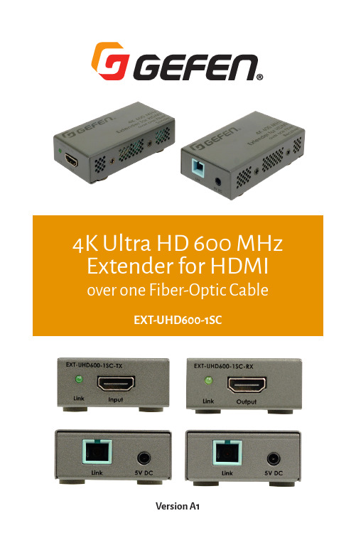
EXT-UHD600-1SCVersion A14K Ultra HD 600 MHz Extender for HDMIover one Fiber-Optic Cable1. Read these instructions.2. Keep these instructions.3. Heed all warnings.4. Follow all instructions.5. Do not use this product near water.6. Clean only with a dry cloth.7. Do not block any ventilation openings. Install in accordance with the manufacturer’sinstructions.8. Do not install or place this product near any heat sources such as radiators, heat registers,stoves, or other apparatus (including amplifiers) that produce heat.9. Do not defeat the safety purpose of the polarized or grounding-type plug. A polarizedplug has two blades with one wider than the other. A grounding type plug has twoblades and a third grounding prong. The wide blade or the third prong are provided for your safety. If the provided plug does not fit into your outlet, consult an electrician for replacement of the obsolete outlet.10. Protect the power cord from being walked on or pinched particularly at plugs,convenience receptacles, and the point where they exit from the apparatus.11. Only use attachments/accessories specified by the manufacturer.12. To reduce the risk of electric shock and/or damage to this product, never handle or touchthis unit or power cord if your hands are wet or damp. Do not expose this product to rain or moisture.13. Unplug this apparatus during lightning storms or when unused for long periods of time.14. Refer all servicing to qualified service personnel. Servicing is required when theapparatus has been damaged in any way, such as power-supply cord or plug is damaged, liquid has been spilled or objects have fallen into the apparatus, the apparatus has been exposed to rain or moisture, does not operate normally, or has been dropped.15. Batteries that may be included with this product and/or accessories should never beexposed to open flame or excessive heat. Always dispose of used batteries according to the instructions.For the latest warranty coverage information, refer to the Warranty and Return Policy under the Connect section of the Gefen Web site at /connect/warranty-and-return-policyTechnical Support(707) 283-5900 (800) 472-55558:00 AM to 5:00 PM Monday - Friday, Pacific Time Email*****************WebMailing AddressGefenCore Brands, LLCc/o Customer Service1800 S McDowell BlvdPetaluma, CA 94954 USACongratulations on your purchase of the Gefen 4K Ultra HD 600 MHz Extender for HDMI over one Fiber-Optic Cable. Your complete satisfaction is very important to us.The Gefen EXT-UHD600-1SC is a compact and high-performance solution for extend-ing uncompressed, full-bandwidth HDMI 2.0 audio/video with HDR (standard 10-bit and Dolby Vision™), up to 200 meters (660 feet), over a single strand of SC-terminated 50/125 µm OM3 or better multi-mode fiber-optic cable.It supports 18.2 Gbps of bandwidth and 600 MHz TMDS Clock frequency, the highest specified under the HDMI 2.0 standard. Full bandwidth support allows the Gefen ex-tender to accommodate resolutions up to 4K Cinema-DCI (4096 x 2160 up to 60 Hz 4:4:4), and 4K Ultra HD (3860 x 2160 up to 60 Hz, 4:4:4) along with HDR (High Dynamic Range). HDCP 2.2 and the legacy HDCP 1.4 are both supported. The EXT-UHD600-1SC also sup-ports 1080p Full HD, WUXGA (1920 x 1200), 3DTV, and Deep Color (up to 1080p resolution). Highest performance multichannel digital audio including 7.1 channels of LPCM and HBR (High Bit Rate) digital audio formats, such as Dolby Atmos®, Dolby® TrueHD, DTS:X™, and DTS-HD Master Audio™ are passed through to the HDMI outputs.There is full electrical isolation between the Sender and the Receiver, meeting the strin-gent safety and EMC requirements for critical applications.This extender can be powered from sources and displays featuring powered USB ports, or by using external power supplies.The Sender and Receiver are plug-and-play, and work without any set-up.Compact enclosures are easy to install and can be hidden away. Their sturdy metal en-closures help provide further immunity against Electro-Magnetic Interference (EMI) and radiated noise (RFI).Applications include medical imaging, military and industrial command and control rooms, flight simulators, digital signage, gaming, and wherever 4K full-bandwidth uncom-pressed video or end-to-end electrical isolation are essential.• This product operates with SC-terminated single strand OM3 or OM4 (50/125 μm) multimode fiber optic cable. Single mode fiber is not supported.• HDMI cable quality is critical when handling 600 MHz HDMI signals. If the 3.3-foot cables that came with the product cannot be used due to their length, we highly recommend 10-foot or shorter Gefen Locking HDMI cables. They have been designed and tested to work at 600 MHz and reliably transport the full 18.2 Gbps throughput of HDMI 2.0.© 2017 Gefen, LLC. All Rights Reserved. All trademarks are the property of their respective owners.Gefen and Core Brands, LLC reserve the right to make changes in the hardware, packaging, and anyaccompanying documentation without prior notice.This product uses UL-Listed power suppliesFeatures*• Supports 18.2 Gbps bandwidth and 600 MHz TMDS clock• Extension up to 200m (660 feet) over one SC-terminated multi-mode OM3 or better (50/125um) fiber-optic cable• Supports resolutions up to 4K Cinema-DCI (4096 x 2160 up to 60 Hz, 4:4:4), 4K Ultra HD (3860 x 2160 up to 60 Hz, 4:4:4) with HDR-10 and Dolby Vision™ , 1080p Full HD, and WUXGA (1920x1200)• Supports HDCP 2.2 and 1.4• Supports HDR (High Dynamic Range) 10-bit color at 4K 60 Hz 4:2:0 and 4K 24 Hz 4:4:4• Supports Dolby Vision™ HDR• Supports 12-bit Deep Color at 1080p Full HD (60 Hz 4:4:4)• 3DTV pass-through• Lip Sync pass-through• Supports uncompressed LPCM digital audio up to 7.1 channels• Supports up to 7.1 channels of HBR (High Bit Rate) digital audio including Dolby Atmos®, Dolby® TrueHD, DTS:X™, and DTS-HD Master Audio™• Supports the use of DVI sources and DVI displays up to 1080p Full HD and WUXGA (1920x1200), with Gefen CAB-DVI2-HDMI-LCK DVI-to-HDMI cables (not included)• Sturdy metal construction of the enclosures help provide immunity against Electro-Magnetic Interference (EMI) and radiated noise (RFI).• Plug & Play – no configuration or set-up required for most applications• Compact enclosures are easy to install and can be hidden away.*Features and specifications are subject to change without notice. All trademarks and registered trademarks are properties of their respective owners. Copyright© 2017 Core Brands, LLC.Packing ListThe following items are shipped with the 4K Ultra HD 600 MHz Extender for HDMI over one Fiber Optical Cable. If any of these items are not present in the box when you first open it, immediately contact your dealer or Gefen.(1) EXT-UHD600-1SC-TX (Sender unit)(1) EXT-UHD600-1SC-RX (Receiver unit)(2) HDMI-to-HDMI Male-to-Male cables, 3.3 feet(2) USB Type-A-to-DC cables, 2.3 ft(2) EXT-PS52AIP-1.3-6-AL 5V DC power supplies & 2 sets of regional AC plugs(US, UK, EU, & AU)(1) Quick Start GuideConnectors and Indicators (8)Sender Unit (8)Receiver Unit (9)Installation (10)Connection Instructions (10)Sample Wiring Diagram (11)Specifications (12)Sender UnitEXT-UHD600-1SCSenderReceiver UnitReceiverConnection Instructions►Video1. Connect the included HDMI cable between the 4K source and the Input port on theSender unit.2. Connect a 4K display to the Output port on the Receiver unit, using the included HDMIcable.►Fiber3. Connect a single SC-terminated OM3 or better (50/125 μm) multimode fiber optic cable,up to 660 feet (200 meters), between the Link port on the Sender unit and the Link port on the Receiver unit.►Power4. Connect the included 5V DC power supplies to the 5V DC port on both the Sender andReceiver unit.5. Connect the opposite end of the power supplies to available electrical outlets.6. Alternatively, you can use the USB-to-DC cables that are also included. Make sure thatthe USB port is powered and can supply 5V DC at 2A.►Indicators7. The Link indicators on both units will light once all connections are complete and theunits, the source, and the display are powered up.Sample Wiring DiagramNOTE: Features and specifications are subject to change without notice. All trademarks and registered trademarks are properties of their respective owners. Copyright© 2017 Core Brands, LLCThis page left blank intentionally*PreferredCore Brands, LLC1800 S McDowell Blvd. Petaluma CA 94954, USA (707) 283-5900 (800) 472-5555。
HDMI over CAT6扩展器-4K 60Hz-330 ft. (100 m) 产品 ID S
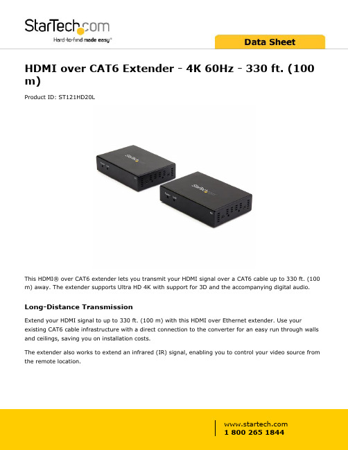
HDMI over CAT6 Extender - 4K 60Hz - 330 ft. (100 m)Product ID: ST121HD20LThis HDMI® over CAT6 extender lets you transmit your HDMI signal over a CAT6 cable up to 330 ft. (100 m) away. The extender supports Ultra HD 4K with support for 3D and the accompanying digital audio.Long-Distance TransmissionExtend your HDMI signal to up to 330 ft. (100 m) with this HDMI over Ethernet extender. Use your existing CAT6 cable infrastructure with a direct connection to the converter for an easy run through walls and ceilings, saving you on installation costs.The extender also works to extend an infrared (IR) signal, enabling you to control your video source from the remote location.Astonishing 4K Picture QualityThis HDMI Ethernet extender supports a 4K 60Hz (3840 x 2160) UHD resolution, providing four times the picture quality of high-definition (1080p), ensuring a crystal-clear picture that's ideal for displaying your 4K video content in office buildings, airports, retail settings and more.Plus, because the extender supports 1080p and lower resolutions at up to 460 feet away, you can comfortably use this extender to make any video source look great.Compatible with HDCP 2.2 DevicesConnect your HDMI devices and displays with confidence, knowing this extender is HDCP 2.2 compliant. This lets you harness the capabilities of HDMI-enabled devices such as Blu-ray players or online streaming devices in higher resolutions. It is also backward compatible with previous generations of HDMI and HDCP.ST121HD20L is backed by 2-year warranty with free lifetime technical support.Certifications, Reports and Compatibility Applications•Extend your 4K HDMI signal in offices, building lobbies, shoppingcenters, airports and more•Optimize placement of your demo stations at tradeshows and in auditoriums•Use existing CAT6 infrastructure to create digital signageFeatures•Maintains astonishing picture quality up to 330 ft. (100 m) away, with support for UltraHD 4K over non-proprietary CAT6 cabling•Also supports HD 1080p video resolutions at distances up to 460 ft.(140 m)•Hassle-free, professional installation with included mounting brackets •Supports all known HDMI audio formats including Dolby True HD, Dolby Digital and DTS-HD•Ensured compatibility with HDCP 1.4 / 2.2Warranty 2 YearsHardware Audio YesAV Input HDMIAV Output HDMICabling Cat 6 UTPChipset ID Norelsys NS 5730, NS5731Performance Audio Specifications7.1 Surround SoundMax Distance140 m / 460 ftSupported Resolutions3840x2160 (4K) 60Hz2560x1600 60Hz1920x1200 60Hz1920x1080 (1080p) 60Hz1280x720 (720p) 60Hz**Lower resolutions and refresh rates, not stated but belowthe maximum, may also be supportedWide Screen Supported YesConnector(s)Connector A 1 - HDMI (19 pin) Female1 - RJ-45 Female1 - 3.5 mm Mini-Jack (3 Position) Female Input1 - 3.5 mm Mini-Jack (3 Position) Female Output1 - 3.5 mm Mini-Jack (3 Position) FemaleConnector B 1 - HDMI (19 pin) Female1 - RJ-45 Female1 - 3.5 mm Mini-Jack (3 Position) Female Input1 - 3.5 mm Mini-Jack (3 Position) Female Output1 - 3.5 mm Mini-Jack (3 Position) FemaleIndicators LED Indicators 2 - Power LED2 - Link LEDPower Center Tip Polarity PositiveInput Voltage110V-240V ACOutput Current 3 AOutput Voltage5V DCPlug Type MPower Source 2 AC Adapters IncludedEnvironmental Humidity0% - 95 % RH (No Condensation)Operating Temperature-5°C to 40°C (23°F to 104°F)Storage Temperature-15°C to 55°C (5°F to 131°F)Color BlackPhysicalCharacteristicsMaterial MetalProduct Height 1 in [26 mm]Product Length 4.3 in [11 cm]Product Width 3 in [75 mm]Weight of Product19 oz [537 g]Package Height 3.7 in [9.5 cm]PackagingInformationPackage Length9.6 in [24.5 cm]Package Width7.9 in [20 cm]Shipping (Package) Weight 3.2 lb [1.5 kg]What's in the Box Included in Package 1 - HDMI Transmitter1 - HDMI Receiver1 - CAT6 Cable1 - IR Kit2 - Universal Power Adapters (NA/JP, EU, UK, ANZ)2 - 3.5 mm to DB-9 RS-232 Adapters4 - Mounting Brackets1 - Quick-Start GuideProduct appearance and specifications are subject to change without notice.。
安卓四核TLA18.C V2.1板卡规格书

产品特点
1、采用的 Four CORTEX A7 内核主芯片,主频高达 1.2GHz,GPU 为 mali400X4, 内存 1G,板载 4G 存储空间; 2、采用 Android4.2 操作系统,可支持 APP 扩展; 3、可支持无线鼠标, 4、RJ45 接口可进行有线网络连接; 5、支持 H.264 视频播放; 6、支持 LVDS BYPass HDMI 4K 30P 信号; 7、USB 接口,可连接大容量移动硬盘,同时可连接鼠标与键盘进行操作; 8、支持音乐播放,图片浏览,享受更多家庭娱乐; 9、支持 SD 卡扩展容量 UP to 32G。
VGA 输 入/NC
触摸框 内置电脑
预留 无线 MIC
VG
VGA Audio 输入
RS232
AV1 输入
AV 色 2差 输输 入入
耳 AV
光纤 机 输
输出 输 出
出
TV 输入
USB3. 外置
0
电脑
TECON
A 扩展板
T-VGA-3
深圳泰科晶显有限公司
TLA18.C-规格书
前置 VGA 扩展
VGA 扩展控制(接主板)
深圳泰科晶显有限公司
TECON
TLA18.C-规格书
目录
版本记录.................................................................................................................................... 3 概述............................................................................................................................................ 4
国科环宇OpenVPX产品手册2014版

76
OV8301 3U 图像视频后 IO 板
78
OV8302 3U 标准配置后 IO 板
80
OpenVPX产品简介
OpenVPX是新一代高性能、高可靠计算机标准,国科环宇作为VITA组织会员之一, 秉承满足客户需求的理念,持续自主研发针对航空、航天、车载、舰载等恶劣环 境应用的OpenVPX标准高可靠计算机系列产品。国科环宇提供从整机到主机板、 功能板、接口板和背板等各种部件,以及全面的软件支持和技术服务。
AD接口板
OV4311 3U 四通道2.5Gsps
AD接口板
电源板
OV4312 3U QSFP接口板
后IO板
OV6301 3U 7槽0.85"背板
OV5300 3U K7 FPGA载板
OV5301 3U ProASIC3L FPGA载板
OV5311 3U XMC/PMC载板
OV7301 3U 180W电源板
整机
机箱
OV9370
OV9310Байду номын сангаас
OV93T0
OV96T0
OV96T1
3U 7槽导冷高可靠计算机 高可靠嵌入式GPU计算机 3U 7槽风冷调试平台 6U 8槽风冷上架平台 6U 5槽风冷上架平台
主机板
OV1300
OV1301
OV1302
3U 7槽1.0"导冷机箱 3U 7槽0.85"导冷机箱 3U 4槽 0.85"导冷机箱
OV8300 3U 管理控制后IO板
OV8301 3U 图像视频后IO板
OV8302 3U 标准配置后IO板
1
环境适应性等级
散热方式
LEVEL 0
大屏高清LED冰柱屏发送卡诺瓦科技MCTRL4K用户如何配置文档大全

欢迎您选用西安诺瓦电子科技有限公司(以下简称诺瓦科技)的产品,如果本文档为您了解和使用产品带来帮助和便利,我们深感欣慰。
我们在编写文档时力求精确可靠,随时可能对内容进行修改或变更,恕不另行通知。
如果您在使用中遇到任何问题,或者有好的建议,请按照文档提供的联系方式联系我们。
对您在使用中遇到的问题,我们会尽力给予支持,对您提出的建议,我们衷心感谢并会尽快评估采纳。
版权本文档版权归诺瓦科技所有,未经本公司书面许可,任何单位或个人不得以任何形式对文本内容进行复制、摘录等,违者必究。
商标是诺瓦科技的注册商标。
安全声明为避免可能的危险,请按规定使用此设备。
插座应当装在设备的附近,而且应当便于触及到。
如出现损坏,非专业人士请勿擅自打开维修,请及时与本公司售后联系。
高压危险:本产品的工作电压为100~240V AC。
接地:本产品通过电源的地线与大地相连,请确保接地导体的良好接地。
电磁干扰:设备应远离磁铁、马达及变压器。
防潮:请将设备置于干燥、干净的环境中。
如有液体浸入,请立即拔掉电源插头。
远离易燃易爆危险物品。
禁止液体、金属碎片浸入机器内部,以免引起安全事故。
1外观说明 1前面板 1 后面板 12信号连接 33产品尺寸 44操作动作说明 45主界面 56菜单操作 6第一步输入模式设置 6 第二步输入分辨率设置 6 第三步快捷点屏 7 第四步亮度调节 7 屏体配置 8 画面控制 8 高级设置 9 通讯设置 11 语言设置 117技术规格 128常见问题与注意事项 131 外观说明①:开机键。
短按开机,开机后长按 4~5 秒关机②:USB 接口,仅连接 U 盘(不可接电脑)③:操作屏幕④:旋钮,按下旋钮表示进入或输入确定,旋转旋钮表示选择或参数调节⑤:BACK,退回上层菜单后面板DP 1.2DP 1.2 接口,支持 HDCP 1.3HDMI 2.0HDMI 2.0 接口,支持 HDCP 1.4 和 HDCP 2.2 DUAL DVI-D1/D2双链路 DVI 接口1~1616 路 Neutrik 千兆网口输出OPT1~44 路光纤输出OPT1 对应网口 1~8,OPT2 对应网口 9~16 OPT3 为 OPT1 的备份,OPT4 为 OPT2 的备份ETHERNET控制接口USB IN: 级联输入或与 PC 连接; OUT:级联下一台IN Genlock 同步信号,保证大屏显示画面和外部Genlock 源同步,Genlock 类型:BlackburstLOOP Genlock 的环出端口AC 100-240V ~ 50/60HZ交流电源接口注意:A 型 USB 接口(扁口)禁止直接与控制计算机连接。
LTtray规格书

LTtray规格书產品規格以實際出貨為準,任何疑問請洽傳易科技全省分公司產品概述:SMC6726L3提供無阻斷的線速 (wire-speed) 傳送速率可達8.8 Gbps ,可讓企業網路得到最佳的效能,並提供許多功能讓企業享有絕佳的網路安全與穩定性,支援第三層路由功能RIP/RIPII 、OSPF 還包括VLAN (GVRP)、 IGMP。
Snooping 、QoS/COS 、支援RADIUS 、802.1x 、SSH 、SSLTACACS+、ACL等功能。
產品規格硬體介面:24個 10/100 Base-TX 埠,支援自動調速與自動跳線偵測功能。
支援MiniGBIC 1000Base-SX 、1000Base-LX 與1000Base-Zx可輕鬆擴充網路頻寬。
符合標準:IEEE 802.3 10Base-T 乙太網路IEEE 802.3u 100Base-Tx 乙太網路IEEE 802.ab 1000Base-T 乙太網路IEEE 802.1d Spanning Tree 協定IEEE 802.1w Rapid Spanning Tree 協定IEEE 802.3ad Port aggregation 協定IEEE802.1p服務等級區隔優先程度協定IEEE802.1x效能8.8Gbps 非阻塞式交換結構(non-blocking switching fabric)。
功能支援8,000(含)以上之MAC Addresses 。
支援大型封包(Jumbo Frame)最高可支援9216 byte 。
每一埠都支援廣播流量控制以避免廣播風暴產生。
每一埠都支援802.1x安全認證功能。
最高可支援到255組IEEE 802.1q標準VLAN Group 。
支援IEEE 802.1d Spanning Tree及802.1w Rapid Spanning Tree(RSTP)。
支援第三層路由功能RIPV1/V2、OSPF。
Quidway ME60系列产品规格
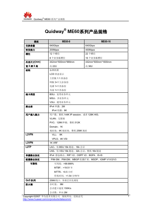
Quidway® ME60系列产品规格描述ME60-8 ME60-16交换容量640Gbps 640Gbps 转发能力200Mpps 400Mpps槽位12个槽位8个业务板槽位22个槽位16个业务板槽位外形尺寸(mm) 宽X深X高442mm*600mm*889mm高22U442mm*600mm*1600mm高36U结构标准机箱LCD状态显示主控板1:1热备份网板3+1冗余备份电源1+1热备份风扇1+1热备份线卡类型BSU:宽带业务单元MSU:多业务单元VSU:通用业务单元路由表IPv4单播:2MIPv4组播:8K用户接入能力用户数:整机144K IP session,或者128K HIS;VLAN:无限制PVC:128K/单板,整机512KDomain:1K地址池:4K地址池,整机256K地址L2VPN VLL: 8KVPLS:4K VSIL3VPN 1K VRFLAC:每BSU 16k隧道、16k会话L2TPLNS:每VSU 16k隧道、32k会话;整机16k隧道单播路由协议IPv4 静态路由、RIP 1/2、OSPF V2、BGP4、IS-IS组播路由协议PIM-SM、PIM-DM、MBGP组播扩展、MSDP、IGMP V1/V2/V3 可靠性可用度:>99.999%MTBF:>19.51年MTTR:<0.5小时停机时间:<1.54分钟/年QoS队列256K/线卡,5级层次化调度防火墙吞吐量: 9M会话建立速度150K/s会话数:单向2M描述ME60-8 ME60-16 SBC 注册用户数:100,000,并发用户数:40,000BHCA:>800K。
华硕M4N68T V2主板手册

三年質保
全國聯保
請用剪刀沿虛線剪下
華碩產品質量保證卡
尊敬的華碩產品用戶:
首先非常感謝您選用華碩公司產品,讓我們有機會向您提供優質的服務。為了使我們的服務讓您 更滿意,在購買後請您認真閱讀此說明並妥善保存此質量保證卡。
保修說明注意事項:
一、 請將此質量保證卡下方的用戶資料填寫完整,並由最終直接經銷商加蓋印章,如果沒有加蓋印 章,請找原購買處補蓋以保障您的權益。請務必保留購買發票或複印件,否則華碩公司將以產 品的出廠日期為參照進行保修。
受保修服務。
四、 若經本公司判斷屬下列因素,則不屬於免費保修服務的範圍,本公司將有權利收取維修費用:
A. 超過華碩提供的質保有效期的主板、顯卡產品。 B. 因遇不可抗拒外力(如:水災、火災、地震、雷擊、颱風等)或人為之操作使用不慎造
成之損害。 C. 未按產品說明書條例的要求使用、維護、保管而造成的損壞。 D. 用戶擅自或請第三方人員自行檢修、改裝、變更組件、修改線路等。 E. 因用戶自行安裝軟件即設定不當所造成之使用問題及故障。 F. 本公司產品序列號標貼撕毀或無法辨認,塗改保修服務卡或與實際產品不符。 G. 其他不正常使用所造成之問題及故障。
或認可之配件所引起之故障與損壞。 D. 因用戶自行安裝軟件及設定不當所造成之使用問題及故障。 E. 計算機病毒所造成之問題及故障。 F. 本公司保修識別標籤撕毀或無法辨認,涂改保修服務卡或與產品不符。 G. 要求華碩提供軟件安裝服務(用戶需自行提供原版軟件)、軟件故障排除或清除密碼等。 H. 其它不正常使用所造成之問題及故障。 用戶手冊中所談論到的產品名稱僅做識別之用,而這些名稱可能是屬於其他公司的註冊商標 或是版權。 關於產品規格最新的升級信息請您到華碩的官方網站瀏覽或是直接與華碩公司聯絡。
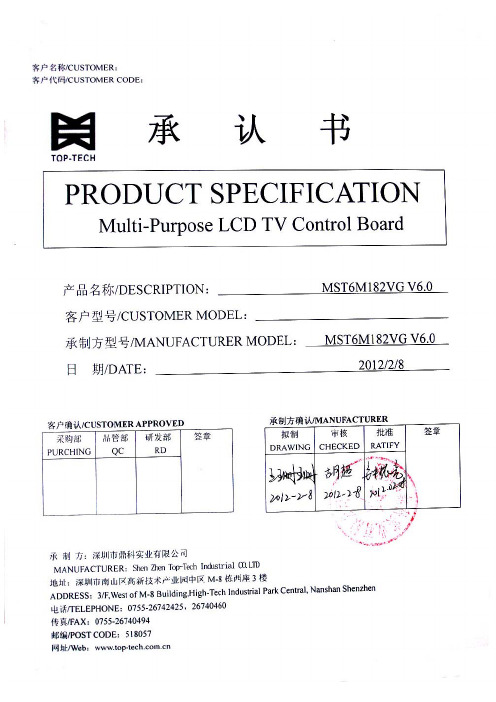
MST6M182VG V6.0 SPEC液晶电视主板规格书
CONTENTSTITLE PAGE CONTENTS········································page 1 of10 RECORD OF REVISIONS····························page 1 of10 GENERAL DESCRIPTION····························page 2 of10 FUNCTION LAYOUT·································page 2 of10 FEATURES·········································page 3 of10 INTERFACE DEFINITION····························page 5 of10 CONTROLLER DIMENSIONS·························page 9 of10KEY & IR BOARD SYSTEM SCHEMATIC··············page 9 of10 OPERATION REQUIREMENT·························page 10 of10RECORD OF REVISIONSREVISION NO. DATE PAGE DESCRIPTION1. GENERAL DESCRIPTIONMST182VG V6.0 is a multi-purpose LCD controller, it is suitable Asia market.It is designed to support FULL HD LCD panel.MST182VG V6.0 can support PC-RGB,HDMI,AV,YPBPR,USB, VGA,TV signal input.It can also support Earphone output.Note:The specification of the board includes the description of all functions. Therefore,our clients can select the functions which they require to produce the board.But the specification can be introduced universally.2. FUNCTION LAYOUTThe following all pictures are a reference only. Please take the actual objects as a standard.Elevation of MST6M182VG V6.0Side Elevation of MST6M182VG V6.03. FEATURESBelow you will find the detailed feature.CHIPSET MST6M182VG MARKET AREA AsiaOSD LANGUAGEEnglish,Chinese,(French,Spanish,Polish,Portuguese,Italian,German,Dutch,Russian)(Option )VIDEO SYSTEM PAL/SECAM,NTSC(Option)SOUND SYSTEM BG ,DK ,I, MTV RECEIVE CHANNELATV:200CVBS 1.0Vp-p +/-5% YPbPr / YCbCr 480i 、480p 、576i 、576p 、720p 、1080i 、1080pFormat Up to 1920*1080@60HZPC-RGBColor 16bit, 24bit, 32bitVIDEO INPUTHDMI 480i 、480p 、576i 、576p 、720p 、1080i 、1080p Build-in powersupply 5V,5VS,12V or only 12V (Option )To panel 5V,12V POWERManage Low power consumable mode: standby ≤0.5WPC-RGB YESAUDIO INPUTAV/YPbPr Audio InputYESEXPANSIONFUNCTIONUSB YESPANELRESOLUTIONSSupport up to 10-bit dual LVDS FULL HD panel interface KEY FUNCTIONS CH-,CH+,MENU,VOL-,VOL+,SOURCE,ON/OFFAUDIO OUTPUT2*8 W @ 8Ω COMB FILTER3D DE-INTERLACE3D WEAK SIGNAL ENHANCEMENTYES NOISE REDUCTION3D NICAM/A2, TELETEXT,BTSC,CC,VCHIPYES TV Input 1 IEC 75 Ω PC-RGB Input 1D-SUB 15PIN terminal blue color HDMI Input 3HDMI terminal CVBS Input 1RCA terminal yellow colorYPbPr Input3RCA terminal green color,blue color andred colorYPbPr Audio InputCVBS Audio Input 2*2RCA terminal white color, red colorInput USB 2 USB terminal To Panel Double LVDS 38PIN/2.0 jackSPDIF 1RCA terminal orange colorTERMINALSOutput Earphone Out 1earphone terminal black color USB MULTIMEDIA PLAYBACK FORMAT MEDIA FILE EXTENSIONPicture JPEG 、BMP 、PNG .jpg 、.bmp 、.pngMovieMPEG1、MPEG2、MPEG4、H264、RM 、RMVB 、MOV 、MJPEG 、VC1、Divx 、FLV.avi 、.mpg 、.dat 、.vob 、.div 、.mov 、.mkv 、.rm 、.rmvb 、.mp4、.mjpeg 、ts 、.trp 、.wmv 、.asf 、.flvMusic WMA 、MP3、M4A 、AAC .wma 、.mp3、.m4aFILE TYPE\THE RELEVANT PARAMETERSRESOLUTIONCOMPRESSIONOPTION SUPPORT BOUNDARIES Progressive JPEGResolution Only Support 1024*768Baseline (”standard”) supportJPEG 15360*8640 Baseline optimizedsupporthomochromatism Support16color Support256color Support 16bit Support24bit SupportBMP 9600*640032bit supportNo interlacingSupport PNG 9600*6400InterlacedResolution Only Support 1200*800*Realize that only when you gain the copyright of the corresponding USB functions ,can the above-mentioned USB functions be used. 4. INTERFACE DEFINITIONCN1 ( 13PIN/2.0 ) MAIN POWER SUPPLYNO.SYMBOLDESCRIPTIONELECTRIC CHARACTER1 12VA2 12VA+12V DC Power supply2A+Panel Electric Current +electric Current of extended module 3 GND4 GND5 GND Ground ---6 5V7 5V+5V DC Power supply2A+Panel Electric Current + electricCurrent of extended module 8 5VS +5V DC Power standby 1A 9 PW ON/OFF --- 10 5V 11 5V+5V DC Power supply2A+Panel Electric Current + electricCurrent of extended module 12 GND Ground ---13 GND Ground ---CN2 (5PIN/2.0) DVD POWER SUPPLYNO. SYMBOL DESCRIPTION1 12VIN +12V DC Power supply2 GND Ground3 GND Ground4 5V_DVD DVD +5V DC Power supply5 5V_DVD DVD +5V DC Power supplyCN4( 6PIN/2.0 ) INVERTER INTERFACENO. SYMBOL DESCRIPTION ELECTRIC CHARACTER1 GNDGround ---2 GNDadjustableadjustment 0-5V3 ADJUST Brightness4 ON/OFF Back-light ON/OFF control 5V ,1K ohm output impedance5 12VA +12V DC Power supply INVERTER Power Supply6 12VA +12V DC Power supply INVERTER Power SupplyCN5 (4PIN/2.0) DVD DEBUGGING INTERFACENO. SYMBOL DESCRIPTION1 GND Grounddata2 DVD-TXD Transmitdata3 DVD-RXD ReceiveIR4 DVD_IR DVDCN6 (2PIN/2.0) EXTERNAL MEMC CONTROL I2CNO. SYMBOL DESCRIPTION1 SDA I2C Master bus for SDA2 SCL I2C Master bus for SCLCN7 (9PIN/2.0) KEY BOARD INTERFACENO. SYMBOL DESCRIPTION1 GND Ground2 CH- CH-keyKey3 CH+ CH+4 MENU MENUKeyKey5 VOL- VOL-Key6 VOL+ VOL+7 GND GroundKey8 SOURCE SOURCEkey9 ON/OFF ON/OFFCN8 (5PIN/2.0) REMOTE RECEIVER INTERFACENO. SYMBOL DESCRIPTION1 GND Groundreceiver2 IR_IN Remote3 LED_G Greenindicatorindicator4 LED_R Red5 IR_VCC +5V DC power supplyCN9 (2*19PIN/2.0) LVDS PANEL INTERFACENO. SYMBOL DESCRIPTION1 VDD Power for panel2 CT mode pin for panel3 VDD Power for panel4 GNDGround5 GND6 GND7 RXO0- LVDS ODD 0- Signal8 RXO0+ LVDS ODD 0+ Signal9 RXO1- LVDS ODD 1- Signal10 RXO1+ LVDS ODD 1+ Signal11 RXO2- LVDS ODD 2- Signal12 RXO2+ LVDS ODD 2+ Signal13 GNDGround14 GND15 RXOC- LVDS ODD Clock- Signal16 RXOC+ LVDS ODD Clock+ Signal17 RXO3- LVDS ODD 3- Signal18 RXO3+ LVDS ODD 3+ Signal19 RXE0- LVDS EVEN 0- Signal20 RXE0+ LVDS EVEN 0+ Signal21 RXE1- LVDS EVEN 1- Signal22 RXE1+ LVDS EVEN 1+ Signal23 RXE2- LVDS EVEN 2- Signal24 RXE2+ LVDS EVEN 2+ Signal25 GND Ground26 GND Ground27 RXEC- LVDS EVEN Clock- Signal28 RXEC+ LVDS EVEN Clock+ Signal29 RXE3- LVDS EVEN 3- Signal30 RXE3+ LVDS EVEN 3+ Signal31 RXE4- LVDS EVEN 4- Signal32 RXE4+ LVDS EVEN 4+ Signal33 RXO4- LVDS ODD 4- Signal34 RXO4+ LVDS ODD 4+ Signal35 SCL SCL36 SDA SDAflag37 3D_FLAG 3Dbrightness adjustment38 PB_ADJUST Back-lightCN10 (4PIN/2.0) DEBUGGING INTERFACENO. SYMBOL DESCRIPTION1 GND Grounddata2 UART-RX Receivedata3 UART-TX Transmit4 +5V_Standby +5V Power supplyCN28 (9PIN/2.0) YPBPR INPUTNO. SYMBOL DESCRIPTION1 Y Y signal input2 GND Ground3 PB PB signal input4 GND Ground5 PR PR signal input6 GND Ground7 R YPBPR right audio input8 GND Ground9 L YPBPR left audio input CN30 (4PIN/2.54) SPEAKER INTERFACENO. SYMBOL DESCRIPTION1 R+ Positive right audio channel out2 R- Negative right audio channel out3 L- Negative left audio channel out4 L+ Positive left audio channel out5. CONTROLLER DIMENSIONSThe dimension is identical to the actual objects.But maybe exist the slight error of measures about 1%.It is allowed in design.6. KEY & IR BOARD SYSTEM SCHEMATICMST6M182VG V6.0 Specification- 10 -7. OPERTION REQUIREMENT· Do not pressed and distorted. · Keep away from static and water. · Relative humidity: ≤80%· Storage temperature:-10~ +60℃ · Operation temperature:0~ +40℃。
诺瓦科技LED控制卡MCTRL4K规格书

Specifications Independent Controller MCTRL4KRev1.0.1 NS1601000126OverviewMCTRL4K is an independent master controller developed by NovaStar with an epoch-making significance. The loading capacity of a single unit is up to 4096x2160@60Hz, which is able to meet the on-site requirements of oversized LED displays. MCTRL4K makes it easier to create stunning visual effects for users.MCTRL4K also can be used as two independent master controllers, which makes it more flexible to load LED displays.The design of MCTRL4K is innovative. It allows to configure a display at any time without PC.Various video inputs such as DP, HDMI, dual-link DVI etc. and outputs of 16-c hannel Neutrik Gigabit Ethernet ports as well as 4-channel optical fiber ports are supported.Features1)Complete video input interfaces: DP1.2 x 1, HDMI2.0 x 1, dual-link DVIx 2;2)Supports 16-channel Neutrik Gigabit Ethernet outputs and 4-channeloptical fiber outputs and maximum loading capacity of a single unitup to 4096x2160@60Hz;3)Supports two operating modes during dual-link DVI input: mosaicand multi-card;4)Innovative design to enable smart configuration which has greatlyshortened the time for stage preparation;5)NovaStar's G4 engine to create stable and flicker-free pictures withoutscanning lines, and bring smooth images with a good sense oflayering;6)Supports NovaStar's latest pixel-by-pixel calibration technology, theprocess of which is fast and efficient;7)Enables white balance calibration and color gamut mapping based onthe different features of LEDs on the display to ensure the realrestoration of color;8)Screen configuration can be done at any time without PC;9)Manual adjustment of screen brightness, which makes it much easierand quicker;10)Multiple controllers are able to be cascaded for uniform control.DimensionsDimensions of MCTRL4K (mm) Appearance Front panelThe top section of the screen displays productand its IP address. The meaning s of other sections are described asbelow:A: Input status of signal source. Blue indicates it has signal while gray indicates no signal.B: Current input source and its resolution,information of two DVI sources will be displayed alternately here when dual-link DVI is selected as input.NOVASTARTECHCO.,LTD.R e a r p a n e lC: Width, height and frame rate of the screen under configuration;D: Status, the meanings of each status icon are introduced as follows: Supply voltage of mainboard core; Temperature inside the controller; Brightness of the LED display;DVI1 and DVI2 sources are not synchronous(in mosaic mode), DVI1 and DVI2 sources are synchronous(in mosaic mode); Control interface is not connected;USB port is used as control interface; Ethernet port is used as control interface; Operation screen is not locked; Operation screen is locked.E: Connection status of Ethernet ports. Blue indicates that the connection is available and the port works as master control while gray indicates the port is not connected or the connection is unavailable. Mark on the upper left corner of the icon indicates that the connection is available and the port is in redundancy state. F: Connection status of optical fiber ports. Blue indicates that the connection is available and the fiber port works as master control while gray indicates the port is not connected or the connection is unavailable. Mark on the upper left corner of the icon indicates that the connection is available and the port is in redundancy state.Inputs DP 1.2 DP 1.2 interface supports HDCP 1.3 HDMI 2.0 and HDCP 2.2 HDMI 2.0 interfacesupports HDCP 1.4Specifi cation。
Smart 4K全能转换器使用说明书

Smart 4K 全能转换器使用说明书成都卓元科技有限公司(索贝集团成员)1、 产品使用1.1、前面板Smart 4K REF:None inPort:12G-SDI Manual Mode In:2160P50 SDR BT.709 2SI Out:2160P50 SDR BT.709 2SIIN SET IN H/S HD MODE2SI SQDOUT H/SNEXTPOWER说明:1.2、后面板说明:2、产品管理使用浏览器进行配置。
浏览器要求:IE9以上版本、Chrome 57以上版本。
2.1、管理连接2.2、登录web配置页面主机配置网口(NMS口)默认IP地址:192.168.1.10主机web登录默认账号:admin,默认密码:admin,需注意区分大小写。
2.3、设备状态登录主机web配置页面后,在状态页面中可查看主机当前状态等信息。
2.4、同步方式设置配置主机同步信号方式。
2.5、系统设置此页面可对主机相关参数进行配置。
参数修改后,需点击【设置】图标才能生效,部分参数修改后需要重启主机,请按提示进行操作。
✧网络设置:根据系统网络IP地址规划,修改卫星校时器主机网口IP地址相关参数,使其符合网络IP地址规划要求。
注:修改后的网口IP地址可在主机前面板液晶显示屏中查看。
✧密码设置:修改web配置账户登录密码,修改完成后请妥善保管好登录密码。
✧系统设置:【重置】:将主机参数恢复到出厂默认值。
【重启】:部分参数修改后需要重启主机才能生效,请按提示进行。
2.6、固件更新按提示选择新固件后进行主机固件更新。
更新固件时请遵循页面注意事项。
ATEN 520M 4x4 6x4+2 8x8 16x16 HDMI 矩阵开关说明书
This symbol, a lightning flash with arrowhead, drawn withinan equilateral triangle, is intended to alert the user to thepresence of uninsulated dangerous voltage within theproduct’s enclosure that may be of sufficient magnitude toconstitute a risk of electric shock to persons.The exclamation point within an equilateral triangle isintended to alert the user to the presence of importantoperating and maintenance (servicing) instructions in the literature accompanying the appliance.To reduce the risk of fire or electric shock, read and follow all instructions and warnings in this manual. Keep this manual for future reference.1. Do not expose this apparatus to rain or moisture. Do not expose this equipment to dripping or splashing, andensure that no objects filled with liquids, such as vases, are placed on the equipment. Do not use this apparatus near water.2. Do not remove cover. No user serviceable parts inside.3. Clean only with a dry cloth.4. Do not block any ventilation openings. Install according to manufacturer’s instructions.5. Do not install near any heat sources such as radiators, heat registers, stoves or other apparatus (includingamplifiers) that produce heat.6. Do not override the safety purpose of the polarized or grounding plug. A polarized plug has two blades, oneof which is wider than the other. A grounding plug has two matching blades and a third grounding prong. The wide blade or the third prong is provided for your safety. If the provided plug does not fit into your outlet,consult an electrician for replacement of the obsolete outlet.7. Protect the power cord from being walked on or pinched, particularly at the plug end and where the powercord is attached to the apparatus.8. Only use attachments and accessories specified by the manufacturer.9. Refer all servicing to qualified service personnel. The apparatus requires service when it is damaged in any way(for example: when the power supply cord or plug is damaged, when liquids have been spilled onto or objects have fallen into the apparatus, the apparatus has been exposed to rain or moisture, does not operate normally, or has been dropped.)10. To completely disconnect this equipment from power, disconnect the power supply cord from the poweroutlet.1. Overview (4)2. Models (4)3. Package Contents (4)4. Downloading the utility (5)5. Utility File Location (5)5.1. B-520-MTRX-230-16x16 Files (5)6. Communicating with the B-520-MTRX-230 (5)6.1. Serial Connection (5)7. Installation & Setup (6)7.1. Basic Installation Diagram (6)7.2. COM Port Settings (6)7.3. Initializing Communication (6)7.4. Stopping Communication (6)8. EDID Configuration (7)8.1. Display EDID for Particular Input/Output (7)8.2. Display EDID for All Inputs / Outputs (8)8.3. Save Configuration for Inputs / Outputs (8)8.4. Learn EDID to Input (9)8.5. Auto EDID Learn (10)9. Advanced Setup Using the Configuration Utility (10)9.1 Output Control (10)10. Firmware Update (11)11. Network Configuration (11)12. Resetting Factory Defaults (12)13. Other Settings (12)13.1. IR Source Routing (12)13.2. Front Panel IR Enable (12)13.3. System IR Enable (12)13.4. Matrix Control from Room Enable (13)13.5. Front Panel Power Button Active (13)14. Input / Output Operation (13)14.1. Connection Status (13)14.2. Input/Output Control (14)15. Appendix: Configuration Utility Home Screens (14)15.1. B-520-MTRX-230-4x4 (14)15.2. B-520-MTRX-230-8x8/6x4+2 (15)15.3. B-520-MTRX-230-16x16 (15)16. Contacting Tech Support (16)17. Warranty (16)This manual outlines the operation and use of the B-520-MTRX-230 PC-based Configuration Utility software. Please read through the entire document before attempting to configure a B-520-MTRX-230. Should you have any questions after reading this document, please contact SnapAV Technical Support.The following models are covered in this manual. The functionality of the Configuration Utility is very similar for all models. Any significant differences are covered by model.• B-520-MTRX-230-4x4• B-520-MTRX-230-6x4+2• B-520-MTRX-230-8x8• B-520-MTRX-230-16x16Before you begin, make sure the following items are available and ready for use:• B-520-MTRX-230• B-520-MTRX-230 Installation Manual• PC running Windows XP or newer Windows OS• Serial Cable to connect the B-520-MTRX-230 to the PC• DB9 to USB adapter (if the PC does not have a serial port built-in)• List of the sources (Inputs) and displays (Outputs) used in the system (consult system chart in the B-520-MTRX-230 manual)• Knowledge of this document and the devices being used in the systemThe software utility is included on the CD provided with the B-520-MTRX-230 and can also be downloaded from the product page at . Check the site for periodic updates to ensure that the latest version of the utility is being used.The B-520-MTRX-230 software utility is a standalone program that does not require installation. Afterdownloading the utility, unzip the downloaded file to a location that is easy to remember and locate when needed, like the example below:• C:\My Documents\Binary\B-520-MTRX-230\ConfigurationUtility5.1. B-520-MTRX-230-16x16 FilesThere are 2 additional “.DLL” type files included with the utility “EXE” that must be placed in the same folder as the utility.6.1. Serial ConnectionThe B-520-MTRX-230 and PC communicate over DB9 straight-through serial cable. Before connecting, verify that the pin configuration of the cable matches the diagram below.Should the PC not have a built in DB9 connection, a USB to RS-232 adapter may be used, however it is strongly recommended that firmware updates are not performed using an adapter.Matrix DB9PC Serial DB9B-520-MTRX-230Pin 2 TxD (Data Transmit) Pin 3 RxD (Data Receive) Pin 5 GNDComputerPin 2 RxD (Data Receive)Pin 3 TxD (Data Transmit)Pin 5 GNDToToToFIGURE 17.1. Basic Installation DiagramComplete the basic installation section to set up the matrix switcher for media distribution before completing any other setup. Use this diagram for reference during basic installation of the matrix switcher, sources, displays and wiring.7.2. COM Port SettingsThe COM port on the PC should be set to 9600 Baud, 1 Stop Bit, No Parity.Select the COM port on the computer that is connected to the B-520-MTRX-230 from the list of available COM ports.If the connected COM port does not appear in the list, refer to the PC’s “Device Manager” to verify that COM ports have been installed and have the right communication settings. Find the Device Manager by searching from the Start menu search bar, or go to Control Panel > Devices and Printers > right-mouse-click and select “Device Manager.”7.3. Initializing CommunicationSelect the “Connect” button to initiate communication between the B-520-MTRX-230 and the computer.Once connected:• Button name will change to “Disconnect”• Status box will change to “Connected” and turn green.If this does not occur after a few moments, perform these steps:1. Verify that the correct COM port is selected;2. Verify communication settings on the PCs COM port;3. Verify that the cable has the correct PIN configuration and that it is functioning correctly.If communication cannot be established after performing these steps, please contact SnapAV tech support.7.4. Stopping CommunicationClick the “Disconnect” button to stop communication between the B-520-MTRX-230 and the computer.The purpose of EDID Configuration is to set the EDID for each input appropriately. This EDID will be passed to the connected source input. Unless the source has a fixed audio or video format, it will transmit content at the best audio and video formats that do not exceed the capabilities specified in the EDID. Note that all outputs on the B-520-MTRX-230 receive the same audio and video format.For example, assume you have two displays (Outputs) that will view the source connected to Input 1. One of the displays is capable of 7.1 multi-channel audio but the other is only capable of stereo audio. In this case, you will store an EDID in Input 1 that restricts the audio to stereo so that both display outputs will produce audio.Select “Configure EDID’s” to access EDID configurations.NOTE: If the PC is not communicating with the B-520-MTRX-230, a “NOT CONNECTED” window will appear.FIGURE 28.1. Display EDID for Particular Input/OutputRead EDID allows you to read the currently stored EDID for each Input and to read the EDID from display (if any) connected to each HDMI and HDBaseT output. Note that EDIDs for the Inputs are displayed in the upper left box while EDIDs for the outputs are displayed in the lower left box.1. Select an input or an output from the dropdown list:2. Select READ to display the information.3. The EDID values for the selected Input or Output will be displayed on the left side of the screen.8.2. Display EDID for All Inputs / Outputs1. READ ALL will read and display the currently assigned EDID for each Input and the EDID from each connecteddisplay.2. The EDID values for all Inputs and Outputs will be displayed on the left side of the screen.8.3. Save Configuration for Inputs / OutputsThis function allows you to save an EDID to disk for future use. A common use of this function is storing the EDIDs for commonly used TVs on disk. These can be recalled from disk (see EDID Learning below) and stored in the EDID Input locations even if the display is not currently connected.1. Select an input or an output from the dropdown list:1. Click “READ” to display the information.2. Click “SAVE” to save the file.3. Browse to the location of your choice to save the configuration file.Suggested Folder Location:C:\My Documents\Binary\B-520-MTRX-230\EDIDConfigurationsFIGURE 34. Create a name for the file that clearly describes the contents.8.4. Learn EDID to InputThe following examples are for the B-520-MTRX-230-8x8, but apply to all models.EDIDs are learned into the B-520-MTRX-230 via the HDMI and HDBaseT output connections.If you are learning from a connected display, the steps below can be followed to learn EDIDs from a display into the B-520-MTRX-230:1. Select the location of the device whose EDID you will learn from in the EDID Learning “From” dropdown list:Available ChoicesNOTE: When “From File” is selected, a window will open when you learn (Step 3 on next page) that allows you to navigate to the location where an EDID configuration file was saved. Select the desired file and select “Open”.1. Select an Input to learn to in the “EDID Learning TO” dropdown list:Available Choices2. Select the LEARN buttonThe selected EDID is stored in the selected Input locations.8.5. Auto EDID LearnThe B-520-MTRX-230 includes an automatic function that will determine the EDID with the best quality video that will work with all connected displays.If all sources (Inputs) are to be viewable on all Displays (HDMI and HDBaseT Outputs), this function provides an easy mechanism for determining the EDIDs to store in all Inputs.If some sources (such as a Blu-Ray player) are only viewed on some displays (Outputs), this method may provide a more restrictive EDID than desired for some displays (Outputs).To see the results of Auto Learn, Read EDID from Input 1. This EDID is stored in all Input EDID locations.NOTE: Auto EDID sets audio to 2ch for all inputs regardless of the capability of the connected displays. If multi-channel audio is desired, embedded EDIDs or Learned EDIDs will need to be used.9.1 Output ControlSelecting “View Outputs” opens a window that allows outputs to be turned on or off. This can be used fortroubleshooting the B-520-MTRX-230 and connections.FIGURE 4The process to update firmware varies slightly between the 4 models; however the types of files loaded are the same as listed below:1. Main- Firmware for the main processor in the matrix.2. DB Board- Firmware for processors that manage Inputs and Outputs.3. HDBaseT- Firmware for the HDBaseT Output Processors.Instructions for updating Firmware on a matrix are detailed on the Firmware Update Page for that product. Before beginning the Firmware Update process download and unzip the latest firmware update from theB-520-MTRX-230 product page for the matrix to be updated and store in a location you will remember on your PC. Be sure the firmware file from the downloaded folder is not compressed or in a compressed folder before updating. IMPORTANT: A hardware RS-232 serial port on a laptop or desktop PC may be more reliable for updating firmware than a USB to RS-232 Adapter. If you have trouble updating using an adapter, please use a PC with a built-in RS-232 port.Displays and sets the Network IP address for all B-520-MTRX-230-Matrix switchers.NOTE: Only Static IP address mode is available – DHCP is not supported.NOTE: The default IP Address for the matrix is 192.168.0.99. The IP Address and Subnet Mask are not reset during FIRMWARE UPDATE or RESET FACTORY DEFAULTS operations.When NETWORK CONFIGURATION is selected, the following window is shown. If you want to know what the current IP address and Subnet Mask are. press the READ FROM DEVICE button. If you have not reset, the IP Address in the matrix iwill be 192.168.0.99 as shown below.To change the values, enter the desired IP Address and Subnet Mask, and then press WRITE TO DEVICE. After changing the values, confirm the update worked correctly by clicking READ FROM DEVICE again.After changing the network configuration, the matrix should be turned off and on again in order to use the new settings.FIGURE 5Select to restore factory default settings for Inputs/Outputs Factory Values:EDIDs for all Inputs: 1080P60, 2 Channel AudioI/O: All Outputs set to Input 1During the installation of a matrix, there are settings that provide Advanced Configuration not available via the remote control. These allow for fine tuning the matrix when used under certain conditions and the settings listed below are not available from the remote.FIGURE 613.1. IR Source Routing:The 3.5mm IR Output to Source jacks on the back of the matrix may be used in two ways. In the default setting, IR coming from the room is routed to the IR Output corresponding to the selected Source (Input). Set IR Source Routing to Yes for this functionality (default). If set to No, the IR coming from a room is routed to the IR output corresponding to the Room (Output) number.13.2. Front Panel IR EnableUse this setting to Enable (default) and Disable the front panel IR receiver. This is useful if the matrix is placed in a location that causes IR flooding from sunlight or other source. This setting only affects the Front Panel IR Receivers.13.3. System IR EnableUse this setting to disable the System IR Input on the back of the matrix.13.4. Matrix Control from Room EnableWhen Set to Yes (default), IR coming from a Room can be used to control the matrix. When set to No, matrixcommands sent from a room will not control the matrix. This setting may be needed if IR flooding from sunlight or other source is sometimes present in one or more rooms.13.5. Front Panel Power Button ActiveUse this feature to Disable/Enable the front panel power button of the matrix when using an Automation System.This will prevent the matrix from being powered OFF which may disrupt matrix control from an automationsystem.The operating status is displayed and control of inputs and outputs is performed with the grid on the left side of the screen. It is provided so that the functionality of the system can be tested and controlled.Here you can perform the following:• View which inputs have sources connected and turned on• View which outputs are un-muted• View which input is assigned to an output• Assign inputs to outputs14.1. Connection StatusFIGURE 7Note that a green box does not indicate if a display is connected or OFF. Should no image be visible on the display, verify that it is connected and ON.14.2. Input / Output Control1. Assign a single Input to an Output2. Select a gray box under the input and next to the output. The box selected will turn green.3. Assign any Input to all Outputs4. Select the Input number in the top row. All boxes under that input will turn green.The home screen for each version of the utility is provided in this section for reference. 15.1. B-520-MTRX-230-4x4FIGURE 815.2. B-520-MTRX-230-8x8/6x4+2FIGURE 9 15.3. B-520-MTRX-230-16x16FIGURE 10If you need further clarification, please call tech support at 866.838.5052, or email******************. For other information, instructional videos, support documentation, or ideas, visit our website and view your item’s product page at .Phone: (866) 838-5052Email:**********************2 Year Limited WarrantyThis Binary product has a 2-Year limited warranty. This warranty includes parts and labor repairs on allcomponents found to be defective in material or workmanship under normal conditions of use. This warranty shall not apply to products that have been abused, modified or disassembled. Products to be repaired under this warranty must be returned to SnapAV or a designated service center with prior notification and an assigned return authorization number (RA)..®Rev: 151117-0930。
诺瓦科技LED发送卡MCTRL4K规格书

MCTRL4K独立主控产品 版本 : V1.0.3 文档编号 :NS110000 427规格书版权所有©2018西安诺瓦电子科技有限公司。
保留一切权利。
非经本公司书面许可,任何单位和个人不得擅自摘抄、复制本文档内容的部分或全部,并不得以任何形式传播。
商标声明声明欢迎您选用西安诺瓦电子科技有限公司(以下简称诺瓦科技)的产品,如果本文档为您了解和使用产品带来帮助和便利,我们深感欣慰。
我们在编写文档时力求精确可靠,随时可能对内容进行修改或变更,恕不另行通知。
如果您在使用中遇到任何问题,或者有好的建议,请按照文档提供的联系方式联系我们。
对您在使用中遇到的问题,我们会尽力给予支持,对您提出的建议,我们衷心感谢并会尽快评估采纳。
规格书更新记录更新记录规格书目录目录更新记录 (ii)1安全说明 (1)1.1存储和运输安全 (1)1.2安装和使用安全 (1)2概述 (2)3功能特性 (3)4外观说明 (5)5尺寸图 (7)6规格参数 (8)独立主控MCTRL4K规格书1安全说明1安全说明本章描述独立主控MCTRL4K的安全说明,目的是保证产品的存储、运输、安装和使用安全。
安全说明适用于所有接触和使用产品的人员。
首先请注意以下几点:●请阅读所有说明。
●请保留所有说明。
●请遵循所有说明。
1.1存储和运输安全●请注意防尘防水。
●请避免阳光长时间直射。
●请勿靠近热源和火源。
●请勿放置在易爆气体环境中。
●请勿放置在强电磁环境中。
●请将产品放在稳固的位置,以防坠落造成产品损坏或人身伤害。
●请保存包装箱和包装材料。
存储和运输产品时可以使用。
为了最大程度地保护设备,请将产品按照出厂时的原始包装重新包好。
1.2安装和使用安全●只有通过培训的专业人员才可以安装产品。
●禁止带电插拔。
●请确保设备安全接地。
●请注意触电危险。
●请佩戴防静电护腕,穿戴绝缘手套。
●请勿将产品安装在震动多或强的环境中。
●请定期除尘。
●请勿擅自维修产品,您可以随时联系诺瓦科技。
微专米 G.Fast 双频通道线驱动器数据表说明书

Le87282G.FastDual Channel Line DriverData Sheet FEATURES•Supports two independent channels ofhigh frequency G.Fast transmission•Supports VDSL2 and ADSL2+ operation•Very low power dissipation–Class AB operation• 5 programmable states–Independent channel control•No external gain resistors required•Operates from a wide range of supply voltages•Small footprint package–28-pin (4 mm x 5 mm) QFN•RoHS compliantAPPLICATIONS•G.Fast Line Driver•VDSL2 Line Driver•ADSL2+ CPE Line DriverDESCRIPTIONThe Le87282 is a dual channel differential amplifierdesigned to drive G.Fast transmission signals as well ashigher power VDSL2 and ADSL2+ signals, all with verylow power dissipation. The Le87282 contains two pairsof wideband amplifiers designed with Microsemi’s HV15Bipolar SOI process for low power consumption.The line driver gain is fixed internally. The amplifiers arepowered from a single supply.The device can be programmed to one-of-three presetBias levels or to impedance controlled Disable orStandby states. Each channel can be controlledindependently. The control pins respond to input levelsthat can be generated with a standard tri-state GPIO.The Le87282 is available in a 28-pin (4 mm x 5 mm)QFN package with exposed pad for enhanced thermalconductivity.ORDERING INFORMATIONLe87282MQC 28-pin QFN Green Package TrayLe87282MQCT 28-pin QFN Green Package Tape and ReelThe green package meets RoHS2 Directive2011/65/EU of theEuropean Council to minimize the environmental impact of electricalequipment.Version 6 January 2019Document Code PD-000286414TABLE OF CONTENTSFeatures. . . . . . . . . . . . . . . . . . . . . . . . . . . . . . . . . . . . . . . . . . . . . . . . . . . . . . . . . . . . . . . . . . . . . . . . . .1 Applications . . . . . . . . . . . . . . . . . . . . . . . . . . . . . . . . . . . . . . . . . . . . . . . . . . . . . . . . . . . . . . . . . . . . . . .1 Description . . . . . . . . . . . . . . . . . . . . . . . . . . . . . . . . . . . . . . . . . . . . . . . . . . . . . . . . . . . . . . . . . . . . . . . .1 Ordering Information. . . . . . . . . . . . . . . . . . . . . . . . . . . . . . . . . . . . . . . . . . . . . . . . . . . . . . . . . . . . . . . . .1 Block Diagram . . . . . . . . . . . . . . . . . . . . . . . . . . . . . . . . . . . . . . . . . . . . . . . . . . . . . . . . . . . . . . . . . . . . .1 Connection Diagram. . . . . . . . . . . . . . . . . . . . . . . . . . . . . . . . . . . . . . . . . . . . . . . . . . . . . . . . . . . . . . . . .3 Pin Descriptions . . . . . . . . . . . . . . . . . . . . . . . . . . . . . . . . . . . . . . . . . . . . . . . . . . . . . . . . . . . . . . . . . . . .4 Absolute Maximum Ratings . . . . . . . . . . . . . . . . . . . . . . . . . . . . . . . . . . . . . . . . . . . . . . . . . . . . . . . . . . .5 Thermal Resistance . . . . . . . . . . . . . . . . . . . . . . . . . . . . . . . . . . . . . . . . . . . . . . . . . . . . . . . . . . . .5 Package Assembly. . . . . . . . . . . . . . . . . . . . . . . . . . . . . . . . . . . . . . . . . . . . . . . . . . . . . . . . . . . . .5 Operating Ranges . . . . . . . . . . . . . . . . . . . . . . . . . . . . . . . . . . . . . . . . . . . . . . . . . . . . . . . . . . . . . . . . . .5 Device Specifications. . . . . . . . . . . . . . . . . . . . . . . . . . . . . . . . . . . . . . . . . . . . . . . . . . . . . . . . . . . . . . . .6 State Control. . . . . . . . . . . . . . . . . . . . . . . . . . . . . . . . . . . . . . . . . . . . . . . . . . . . . . . . . . . . . . . . . . . . . . .7 Applications . . . . . . . . . . . . . . . . . . . . . . . . . . . . . . . . . . . . . . . . . . . . . . . . . . . . . . . . . . . . . . . . . . . . . . .7 Line Driver Protection. . . . . . . . . . . . . . . . . . . . . . . . . . . . . . . . . . . . . . . . . . . . . . . . . . . . . . . . . . .8 Physical Dimensions . . . . . . . . . . . . . . . . . . . . . . . . . . . . . . . . . . . . . . . . . . . . . . . . . . . . . . . . . . . . . . . .9 28-pin QFN . . . . . . . . . . . . . . . . . . . . . . . . . . . . . . . . . . . . . . . . . . . . . . . . . . . . . . . . . . . . . . . . . .9CONNECTION DIAGRAMNote:1.Pin 1 is marked for orientation.2.The Le87282 device incorporates an exposed die pad on the underside of its package. The pad acts as a heat sink and must be connectedto a copper plane through thermal vias, for proper heat dissipation. It is electrically isolated and maybe connected to GND.PIN DESCRIPTIONSPin #Pin Name Type Description1IREF Input Device internal reference current. Connect a resistor (R REF ) to GND.2VINA Input Non-inverting input of amplifier A 3VINB Input Non-inverting input of amplifier B 4GND Ground Reference ground5GND 6VINC Input Non-inverting input of amplifier C 7VIND InputNon-inverting input of amplifier D 8NC No internal connection 9S2Input Channel 2 state control 10VOUTD Output Amplifier D output11EN2Input Enable Channel 2 transmission 12VOUTC Output Amplifier C output13NC No internal connection14NC 15NC 16NC 17GND GroundReference ground 18VS PowerPower Supply19VS 20VS 21GND GroundReference ground22NC No internal connection23NC 24NC 25VOUTB Output Amplifier B output26EN1Input Enable Channel 1 transmission 27VOUTA Output Amplifier A output 28S1InputChannel 1 state controlExposed padElectrically isolated thermal conduction pad, can be groundedABSOLUTE MAXIMUM RATINGSStresses above the values listed under Absolute Maximum Ratings can cause permanent device failure.Functionality at or above these limits is not implied. Exposure to absolute maximum ratings for extended periods can affect device reliability .Notes:1.Continuous operation above 145°C junction temperature may degrade device reliability.2.See Thermal Resistance .3.No air flow.Thermal ResistanceThe thermal performance of a thermally enhanced package is assured through optimized printed circuit board layout.Specified performance requires that the exposed thermal pad be soldered to an equally sized exposed copper surface, which, in turn, conducts heat through multiple vias to larger internal copper planes.Package AssemblyThe green package devices are assembled with enhanced, environmental compatible lead-free, halogen-free, and antimony-free materials. The leads possess a matte-tin plating which is compatible with conventional board assembly processes or newer lead-free board assembly processes.Refer to IPC/JEDEC J-Std-020 Table 4 for recommended peak soldering temperature and Table 5-2 for the recommended solder reflow temperature profile.OPERATING RANGESMicrosemi guarantees the performance of this device over the industrial (-40°C to 85°C) temperature range by conducting electrical characterization over each range and by conducting a production test with single insertion coupled with periodic sampling. These characterization and test procedures comply with the Telcordia GR-357-CORE Generic Requirements for Assuring the Reliability of Components Used in Telecommunications Equipment.Storage Temperature-65 ≤ T A ≤ +150°C Operating Junction Temperature (Note 1)-40 ≤ T j ≤ +150°C VS with respect to GND-0.3 V to +16 V Control inputs with respect to GND -0.3 V to 4 V Continuous Driver Output Current100 mA Maximum device power dissipation, continuous (2) - T A = 85°C, P D 1.7W Junction to ambient thermal resistance (2,3), θJA 36.0°C/W Junction to board thermal resistance (2), θJB18.3°C/W Junction to case bottom (exposed pad) thermal resistance, θJC (BOTTOM)8.9°C/W Junction-to-top characterization parameter (2), ψJT 1.2°C/WESD Immunity (Human Body Model)JESD22 Class 2 compliant ESD Immunity (Charge Device Model)JESD22 Class IV compliantAmbient temperature T A-40°C to +85°C Power SupplyVS with respect to GND:Typical usage+8V to +15V,+12V ± 5%DEVICE SPECIFICATIONSTypical Conditions: As shown in the basic test circuit (Figure 1) with VS = +12 V, R REF = 75 k Ω, and T A = 25°C.Min/Max Parameters: T A = -40 to +85°C.Figure 1.Basic Test Circuit - Channel 1 ShownTable 1.Electrical SpecificationsSymbolParameter Description ConditionMinTyp Max Unit NotesSupply Characteristics P VS Supply Power (per channel)Transmission, P LINE = 4 dBm 470600mW Receive period, Disable state 175250mW I VSSupply Current (per channel)Standby State11.5mAControl Input (S1, S2, EN1, EN2 ) Specifications V IH Input High Voltage 2.03.3 3.6V V IM Input Middle Voltage 1.5V V ILInput Low Voltage -0.300.8V Enable Time 500ns Disable TimeDisable state500nsAmplifier CharacteristicsDifferential Gain VOUT/VIN 18.318.819.1dB Gain Flatness2 − 106 MHz-1.51dB 1V O Output Voltage 10V I O Output Current 150mA 1Z I Input Impedance Differential 131518k ΩZ O Output Impedance Disable state 60ΩAmplifier Dynamic CharacteristicsNoise Input Referred Noise 2 - 106 MHz915nV/1TSDThermal Shutdown Temperature170°CNotes: 1. Not tested in production. Guaranteed by characterization and design.HzSTATE CONTROLS1, EN1 and S2, EN2 pins are used as combinatorial logic inputs to control the line driver operating states. Table 2 and Table 3 show the programmable states for each channel.S1, EN1 and S2, EN2 are tri-state inputs that accept three operating levels. These pins have internal resistors tied to +1.5 V which force a middle logic input level when the control to these pins is tri-stated.Table 2.Channel 1 Control MatrixS1EN1State ApplicationX0DisableX Open Standby01Enable Low Bias ADSL2+Open1Enable Medium Bias VDSL211Enable Full Bias G.FastTable 3.Channel 2 Control MatrixS2EN2State ApplicationX0DisableX Open Standby01Enable Low Bias ADSL2+Open1Enable Medium Bias VDSL211Enable Full Bias G.FastDisable State: Amplifier output = VS/2. The Disable state should be used during the receive period. The device presents a controlled low impedance to the line during this state.Standby State: Amplifier bias current removed. This is the lowest power state. Amplifier output is high impedance. Gain-setting feedback resistors are still connected across amplifier output pins, creating 1300ohm differential impedance at pins.Bias States: Line Driver is active for transmission. States are different only in the amount of bias current to the amplifiers, and therefore power consumption. There is a trade-off between bias current and bandwidth. APPLICATIONSThe Le87282 integrates two sets of high-power line driver amplifiers that can be connected for half-duplex differential line transmissions. The amplifiers are designed to be used with signals up to 106 MHz with low signal distortion. The Le87282 can be used for G.Fast applications as illustrated in Figure 2, or it can be used for VDSL2 or ADSL2+ applications. For VDSL2 or ADSL2+ applications, the output resistor values need to be reduced in order to achieve the desired load power of these applications.Figure 2 shows a G.Fast application circuit with amplifiers A and B in transmission and amplifiers C and D in the receive period (Disable state). Amplifiers C and D drive 0 ohms in the Disable state.Figure 2.Typical G.Fast Application CircuitInput ConsiderationsThe driving source impedance should be less than 100 nH to avoid any ringing or oscillation.Output Driving ConsiderationsThe internal metallization is designed to carry up to about 100 mA of steady DC current and there is no current limit mechanism. The device does feature integrated thermal shutdown protection however with hysteresis. Driving lines with no series resistor is not recommended.Power Supplies and Component PlacementThe power supplies should be well bypassed close to the Le87282 device. A 2.2 µF tantalum capacitor and a 0.1 µF ceramic capacitor for the VS supply is recommended.Line Driver ProtectionHigh voltage transients such as lightning can appear on the telephone lines. Transient protection devices should be used to absorb the transient energy and clamp the transient voltages. The series output termination resistors limit the current going into the line driver and internal clamps. The protection scheme depends on the type of data transformer used and the line protection components used in the front of the data transformer.PHYSICAL DIMENSIONSNote:Packages may have mold tooling markings on the surface. These markings have no impact on the form, fit or function of the de-vice. Markings will vary with the mold tool used in manufacturing.Information relating to products and services furnished herein by Microsemi Corporation or its subsidiaries (collectively “Microsemi”) is believed to be reliable. However, Microsemi assumes no liability for errors that may appear in this publication, or for liability otherwise arising from the application or use of any such information, product or service or for any infringement of patents or other intellectual property rights owned by third parties which may result from such application or use. Neither the supply of such information or purchase of product or service conveys any license, either express or implied, under patents or other intellectual property rights owned by Microsemi or licensed from third parties by Microsemi, whatsoever. Purchasers of products are also hereby notified that the use of product in certain ways or in combination with Microsemi, or non-Microsemi furnished goods or services may infringe patents or other intellectual property rights owned by Microsemi.This publication is issued to provide information only and (unless agreed by Microsemi in writing) may not be used, applied or reproduced for any purpose nor form part of any order or contract nor to be regarded as a representation relating to the products or services concerned. The products, their specifications, services and other information appearing in this publication are subject to change by Microsemi without notice. No warranty or guarantee express or implied is made regarding the capability, performance or suitability of any product or service. Information concerning possible methods of use is provided as a guide only and does not constitute any guarantee that such methods of use will be satisfactory in a specific piece of equipment. It is the user’s responsibility to fully determine the performance and suitability of any equipment using such information and to ensure that any publication or data used is up to date and has not been superseded. Manufacturing does not necessarily include testing of all functions or parameters. These products are not suitable for use in any medical and other products whose failure to perform may result in significant injury or death to the user. All products and materials are sold and services provided subject to Microsemi’s conditions of sale which are available on request.For more information about all Microsemi productsvisit our website at TECHNICAL DOCUMENTATION – NOT FOR RESALE© 2019 Microsemi Corporation. All rights reserved. Microsemi and the Microsemi logo are trademarks of Microsemi Corporation. All other trademarks and service marks are the property of their respective owners.Microsemi Corporation (NASDAQ: MSCC) offers a comprehensive portfolio of semiconductor solutions for: aerospace, defense and security; enterprise and communications; and industrial and alternative energy markets. Products include mixed-signal ICs, SoCs, and ASICs;programmable logic solutions; power management products; timing and voice processing devices; RF solutions; discrete components; and systems. Microsemi is headquartered in Aliso Viejo, Calif. Learn more at .Microsemi Corporate HeadquartersOne Enterprise, Aliso Viejo CA 92656 USA Within the USA: +1 (949) 380-6100Sales: +1 (949) 380-6136。
易曼特6英寸圆形下光盘 dimming 电压选项说明书

Engine / TrimSloped Ceiling example: 7925MDFrame Standard example: 6RN l BAC example: 6RN-BAC1.There is a 3000lm (30) limit with 6" (6RA) IC housings.2.Universal 120-347V is for 0-10v (Z10) dimming configurations only. For 347V non-Z10 dimming,order 347V (3) frame with (U) light engine/trim.3.Interact Pro (RADIO), Emergency (EM6) and Chicago Plenum (LC) are only available with New construction (N) installs.4.EM6 option compatible with new construction (N) frame only. Order CAEM6TSCP ceiling mounting plate accessoryfor remote mounted test switch. EM6 option not compatible with Power over Ethernet or 347V configurations.5. Integral Interact Pro RF sensor enables network lighting control; to be specified with 0-10V light engines only.6. ELV (E) dimming is only compatible with 1000 lm (10), 1500 lm (15), 2000 lm (20) configurations.Not compatible with 347V frame options.7.Specify standard UNV frame for use with 347V light engines.8.The 347V light engine voltage option is available only with Z10 dimming option.For other dimming protocols order (U) light engine and 347V (3) frame.9. Requires IRT9015 IR remote & Interact Pro App for commissioning.** F ailure to properly select the “BAC” suffix could result in you receiving product that is not BAA compliant product withno recourse for an RMA or refund. This BAC designation hereunder does not address (i) the applicability of, or availabilityof a waiver under, the Trade Agreements Act, or (ii) the “Buy America” domestic content requirements imposed onstates, localities, and other non-federal entities as a condition of receiving funds administered by the Department ofTransportation or other federal agencies.EasyLyte downlights are adaptable, and flexible for your changing project needs.EasyLyte is your best choice without sacrificing ease of installation or productquality. Ideal for use in open office, healthcare, design build, and other lightcommercial applications.Standard luminaire = Frame + Engine/Trim + Accessories (optional)Buy American Act of 1933 (BAA)** Compliant luminaire* = Frame-BAC + Engine/Trim-BAC* B AA compliance requires that BAC option be selected for each of frame and engine/trim.Frame and engine/trim will be ordered/shipped together (ex: 6RN-BAC-Z6RDL20835WOCDZ10U-BAC).Accessories (optional) are not currently BAA-compliant.Accessories(Not currently BAA-compliant - learn more on page 2)SBA I nteract Ready System Bridge Accessory with integral occupancy and daylight sensor (compatible with all 0-10V options, see SBA spec sheet)9CAEM6 Field installable Bodine BSL6 6W battery pack with self-test/self-diagnostic for use with new construction frames, 120-277VAMS ActiLume multi-sensor (optional accessory for PoE configurations)CAEM6TSCP Surface mount cover plate to remote mount test switch for EM6 frame option.ICStandard example: Z6RDL20835WOCDZ10U l BAC example: Z6RDL20935WOCDZ10U-BACFeaturesOptics- P rovides a 70° cutoff (physical and reflected)- W ide beam distribution for general illumination - S pun aluminum outer reflector with integral flange painted white- I njection molded plastic trim inserts in splay and baffle options- R eflectors available in painted clear diffuse, white, black and dark bronze Quality of light- Lumen Maintenance: L70 at 60,000 hours - Color consistency: 2 SDCM - 90 CRI minimumConstruction (New Construction)- G alvanized stamped steel for dry / plaster ceilings.- P re-installed telescoping mounting bars (13" - 24")- F rame accommodates C- channel, black iron, and3/4" EMT for mounting distances greater than 24" between joists.- M anufactured from 20 gage galvanized steel construction with rolled edge aperture to guide cutting tools for perfect hole cutting.Max ceiling thickness is 2" (51 mm). Including PoE frame 4.88" (124 mm).Patented install Mounting frame- P re-installed mounting bars allow for fast and tool-less install into T-grid and hat channel ceilings - C lose-cut aperture design eliminates an undesired gap between ceiling material and reflector.- S imple plug-and-play connection between frame and light engine from below the ceiling allows for: • Easy upgrades • Technology changes • Repairs and troubleshootingDimming120/277V- Advance 0-10V 1% dimming- Lutron Hi-lume EcoSystem H Series 1% dimming 347V- I ntegral 347V drivers available for 0-10v (Z10) light engine configurations with standard universal frames. - F or 347V and non-0-10v dimming, order (U) light engine and 347V (3) frame (includes step down transformer). Not compatible with ELV dimming.EmergencyRemote ceiling mounted test switch. Accessory ceiling mounting plate available (CAEM6TSCP) for remote mounted test switch. See Calculite-LyteProfile-EasyLyte Emergency Battery Pack specification sheet for more details.Power over EthernetPowered via Philips PoE lighting controller:complies with FCC rules per Title 47 part 15 (Class A) for EMI / RFI (conducted & radiated). PoE lighting controller accessible from below ceiling. Rated life: 60,000 hrs at 70% lumen maintenance based on IES LM-80-08 and TM-21-11.Sloped Ceiling AdapterMaterial: 16 ga. spun aluminum, matte white finish. Installation: Installs with standard recessed fixture in sloped ceilings without changing the vertical axis of the fixture or its lighting characteristics. Perforated Tabs (4): Provide temporary support for the slope ceiling adapter during installation. Locking Screws (4): Secure slope ceiling adapter to mounting frame of fixture.Support: Fixture must be supported by ceiling structure — not Slope Ceiling Adapter.Options and AccessoriesField Installed Emergency: Refer to Calculite-Lyte-Profile-EasyLyte Emergency Battery Pack specification sheet for more details.CAEM6: Field install EM6 kit with Bodine BSL6 6W battery pack with self-test/self-diagnostic, mounts to new construction frame. Includes ceiling plate for remote test switch.CAEM6TSCP: Ceiling cover plate for remote mounted EM6 test switch. 1" (25mm) hole, 4 ⅜" (109mm) x 2 ⅝" (69mm) rectangular. Includes two mounting screws.ENERGY STAR ® exceptions- 500lm configurations - Black & Dark bronze finishes - P ower Over Ethernet driversLabels and Listings- c ULus listed for wet location -E NERGY STAR ® certified - R oHS certifiedWarranty5 year limited warrantyV isit /warrantiesfor more information on Signify's standard 5- year limited warranty on complete luminaire systems.FinishesWhiteBrightest aperture when illuminated and provides the smoothest transition to most ceilings when off(only available with a white flange).BlackSpecular finish that provides the lowest aperture brightness possible and reduces source identification in a ceiling significantly.Dark BronzeSpecular finish that provides the lowest aperture brightness possible and reduces source identification in a ceiling significantly.Clear diffuseSlightly diffuse clear finish that softens the light and reduces the mirror image effect with traditional aluminum specular finishes(only available witha white flange).Wireless Controls OptionsInteract Pro scalable sensor(System Bridge Accessory with -CS option):• CS is a connected sensor with integral occupancy and daylight sensing and supports wireless mesh connectivity.• The sensor works in the Foundation mode (similar to SpaceWise) when configured without a gateway or in an Interact Pro Advanced or Enterprise mode if a compatible gateway is used.• Interact Pro includes an App, a portal and a broad portfolio of wireless luminaires, lamps and retrofit kits all working on the same system.• Startup is implemented via Interact Pro App (Android or iPhone) & BlueTooth connectivity. The App provides flexibility to choose between a gateway or non gateway mode for setup.• Setup with the gateway requires wired internet access to the gateway. It is possible to add a gateway at a later point.• Prepare project configuration steps remotely and use IRT9015 remote onsite to identify and group devices together.• Compatible with:- SWS200 wireless scene switch- Battery powered IP42 presence sensor OCCsensor IA CM WH 10/1- Battery powered IP42 presence & daylightsensor OCC-DL sensor IA CM IP42 WH- Battery powered IP65 presence sensor OCCsensor IA CM IP65 WH- Battery powered IP65 presence & daylightsensor OCC-DL sensor IA CM IP65 WH• For more information on Interact Pro visit: / interactproscalablesystem.Interact Pro Enterprise(System Bridge Accessory with -SB option):• A wireless IoT connected lighting solution forlarge enterprises that span across multiplefloors, buildings and require multiple gateways.• View all your projects under one dashboard andeasily compare insights from multiple projectsin one view.• Compatible with SWS200 wireless sceneswitch, wireless Occ sensor (OCC SENSORIA CM IP42 WH 10/1) and wireless Day/Occsensor (OCC MULTI SENSOR IA CM WH 10/1) andwireless Occupancy or Daylight & Occupancysensors available.• Use Interact software and insights to increasebuilding efficiency, achieve building wideintegration and optimize space throughoccupancy analytics.• SB option in addition to occupancy and daylightsensing supports advanced IoT capabilitiessuch as people estimation analysis, desklevel temperature & humidity sensing, noiseclassification, and BLE beacon.• Requires compatible Gateway and internetconnectivity for commissioning.• For more information, visit:/office or/systems/system-areas/offices.Emergency Options (ER100)(System Bridge Accessory with -ER100 option):• Power Sensing (Factory default) –Recommended UL924 option requiresunswitched power sense line, absence ofvoltage on the normal circuit triggers luminaireto 100% output• Power Interruption Detection (Field option) –Detects AC power interruption >30ms triggers90 minute emergency mode with luminaire at100% outputRadio only sensor (RADIO):• Integral RADIO only sensor simply enableswireless mesh connectivity to the luminairewithout any occupancy or daylight sensing.• Ideal for applications where sensingfunctionality is managed by other Interactdevices and the luminaire only needs to havewireless connectivity.Wired Controls OptionsInteract Office Wired (PoE):• PoE based IoT connected lighting solution for large enterprises that span across multiple floors, buildings and require multiple gateways.• Use Interact Office software and insights to increase building efficiency, achieve building wide integration and optimize space through occupancy analytics.• Supports advanced IoT Apps on Personal Control, Space Management, wayfinding, room/ desk reservation and offers open APIs for light control and data exchange.• PoE lighting controller is accessible from below.• Integral sensor option for occupancy sensing (PIR) and/or daylight harvesting available for additional energy savings. • Optional integral emergency controller andbattery pack provides 600lm nominal output.• Test switch and indicator light mounted on sideof chassis on one end.• Emergency battery has a 3 month pre-installedshelf life, and must be stored and installedin environments of 20C to 30C (-4F to 86F)ambient, and 45-85% relative humidity.• For more information on Interact Office Wired,visit: /office or/systems/system-areas/offices.Interact Office Wired (PoE), Static White:• A wireless IoT connected lighting solution forlarge enterprises that span across multiplefloors, buildings and require multiple gateways.• View all your projects under one dashboard andeasily compare insights from multiple projectsin one view.• Compatible Zigbee Green Power wall dimmer andwireless Occupancy or Daylight & Occupancysensors available.• Use Interact Office software and insights toincrease building efficiency, achieve buildingwide integration and optimize space throughoccupancy analytics.• Supports advanced IoT Apps on wayfinding,room/desk reservation and offers open APIs• Requires compatible Interact Office Gatewayand internet connectivity for commissioning.• For more information on Interact OfficeWireless, visit: /office or /systems/system-areas/offices.Standard CRI 80 Good color renderingand high efficacyStandard CRI 90Better color renderingand low efficacyAccuRenderBest color rendering,color preference and high efficacyEnjoy design flexibility Full range of products and options:• Available soon in acrossLightolier portfolio for application flexibility• Multiple color temperatures (CCTs) and lumen packages offeredLED Color RecipesShow your true colorsHigh color rendering:• True to life colors to helpenergize your environment andrender better flesh tones criticalfor healthcare hospitality andretail applications.• R a up to 94 CRIR9 up to 67 CRIG a up to 99 CRIC9 up to 94 CRIPromote savingsHigh efficacy, with no penalty:• Energy efficacy compareswell to conventional 80 CRI• Up to 25% more energysavings vs competitor 90 CRI 1• Helps meet Title 24 requirementsAchieve color balanceBest in class color consistency:• Promote aesthetic harmonyin your space with ≤ 2 SDCM• R f up to 92 TM-30R f,h1 up to 91 TM-30R9 up to 100 TM-30R cs,h1up to -5% TM-30Skin & Cosmetics(R9/R13/R15)(Textile)Naturalness(Ra)Color Saturation(Ga)Crisp WhiteDial-up the drama of your display.Highlight the variances in whitetones, add contrast to blacks andcreate a real pleasing sparkleeffect while retaining warmskin tones.Premium WhiteThe new benchmark for retailfashion. Delivering strongerand brighter whites via the bestlighting technology on the marketwith minimal compromise toenergy savings.Premium ColorEnhance the contrast betweencolors and whites to achievenew depths of color renderingfor a vibrant saturated fashion-forward visual experience thatwon't affect the atmosphereand will have a positive effecton energy efficiency.Standard ColorStandard CRI 90AccuRender Technology (CRI 90+)The right light brings colors to life. Our new AccuRender technology helps ensure colors arerendered more accurately and consistently, while doing so as efficiently as CRI 80 products.Photometry2. Wattage: controlled to within 5%3. Correlated Color Temperature: within specs as defined in ANSI_NEMA_ANSLG C78.377-2008: Specifications for the Chromaticity of Solid State Lighting Products.。
华为Metro1000-Metro2050-Metro3000-SDH光传输设备
华为Metro1000 Metro2050 Metro3000 SDH光传输设备各板卡常见华为Metro 1000板卡主控板卡:华为Metro 1000 16xE1/75ohm/2xSTM-4(S-4.1) 主控集成光电光传输模块(-48VDC)16xE1/75ohm/2xSTM-1(S-1.1) 主控集成光电光传输模块(-48VDC)4xEFT/16xE1/75ohm/2xSTM-4(S-4.1) 主控集成光电光传输模块(-48VDC)华为Metro 1000 4xEFT/16xE1/75ohm/2xSTM-1(S-1.1) 主控集成光电光传输模块(-48VDC) 16xE1/75ohm/2xSTM-4(S-4.1)/2xSTM-1(S-1.1) 主控集成光电光传输模块(-48VDC)16xE1/75ohm/4xSTM-1(S-1.1) 主控集成光电光传输模块(-48VDC)4xEFS/16xE1/75ohm/2xSTM-4(S-4.1) 主控集成光电光传输模块(-48VDC)华为Metro 1000 4xEFS/16xE1/75ohm/2xSTM-1(S-1.1) 主控集成光电光传输模块(-48VDC) 32xE1/75ohm/2xSTM-4(S-4.1) 主控集成光电光传输模块(-48VDC)4xEFT/16xE1/75ohm/2xSTM-4(S-4.1)/2xSTM-1(S-1.1) 主控集成光电光传输模块(-48VDC) 16xE1/75ohm/2xSTM-1(S-1.1) 主控集成光电光传输模块(-48VDC)16xE1/75ohm/2xSTM-4(S-4.1) 主控集成光电光传输模块(-48VDC)华为Metro 1000 4xEFT/16xE1/75ohm/2xSTM-4(S-4.1) 主控集成光电光传输模块(-48VDC) 4xEFT/16xE1/75ohm/2xSTM-1(S-1.1) 主控集成光电光传输模块(-48VDC)16xE1/75ohm/2xSTM-4(S-4.1)/2xSTM-1(S-1.1) 主控集成光电光传输模块(-48VDC)16xE1/75ohm/4xSTM-1(S-1.1) 主控集成光电光传输模块(-48VDC)华为Metro 1000 4xEFS/16xE1/75ohm/2xSTM-4(S-4.1) 主控集成光电光传输模块(-48VDC) 4xEFS/16xE1/75ohm/2xSTM-1(S-1.1) 主控集成光电光传输模块(-48VDC)32xE1/75ohm/2xSTM-4(S-4.1) 主控集成光电光传输模块(-48VDC)4xEFT/16xE1/75ohm/2xSTM-4(S-4.1)/2xSTM-1(S-1.1) 主控集成光电光传输模块(-48VDC) SS49SCBA(S-1.1) 16xE1/2xSTM-1(S-1.1) 系统控制板SS49SCBC(S-4.1) 16xE1/2xSTM-4(S-4.1) 系统控制板华为Metro 1000 SS49SCBC(L-4.1) 16xE1/2xSTM-4(L-4.1) 系统控制板SS49SCBE(S-1.1) 2xSTM-1(S-1.1) 系统控制板SS49SCBF(S-4.1) 2xSTM-4(S-4.1) 系统控制板SS49SCBG 系统控制板华为Metro 1000 SS49SCBH(S-1.1) 16xE1(75&120ohm)/2xSTM-1(S-1.1) 系统控制板-ESFP 光模块SS49SCBH(L-1.1) 16xE1(75&120ohm)/2xSTM-1(L-1.1) 系统控制板-ESFP光模块SS49SCBH(L-1.2) 16xE1(75&120ohm)/2xSTM-1(L-1.2) 系统控制板-ESFP光模块SS49SCBI(S-4.1) 16xE1(75&120ohm)/2xSTM-4(S-4.1) 系统控制板-ESFP光模块华为Metro 1000 SS49SCBI(L-4.1) 16xE1(75&120ohm)/2xSTM-4(L-4.1) 系统控制板-ESFP 光模块SS49SCBI(L-4.2) 16xE1(75&120ohm)/2xSTM-4(L-4.2) 系统控制板-ESFP光模块常见常见华为Metro 1000板卡光通信单板:SS48OI4DA(S-4.1,SC) 2*STM-4光接口板(S-4.1,SC)华为Metro 1000 SS48OI4DA(L-4.1,SC) 2*STM-4光接口板(L-4.1,SC)SS48OI4DA(L-4.2,SC) 2*STM-4光接口板(L-4.2,SC)SS49SCBA(L-1.2) 16xE1/2xSTM-1(L-1.2) 系统控制板SS42OI2-D(S-1.1 SC) 2xSTM-1光接口板(S-1.1,SC)SS43TDA 多路音频数据接口板华为Metro 1000 SS42OI2-S(S-1.1 SC) STM-1光接口板(S-1.1,SC)SS42OI2-S(Ie-1 SC) STM-1光接口板(Ie-1,SC)SS42OI2-S(L-1.1 SC) STM-1光接口板(L-1.1,SC)SS42OI2-S(L-1.2 SC) STM-1光接口板(L-1.2,SC)SS42OI2-D(L-1.1 SC) 2xSTM-1光接口板(L-1.1,SC)华为Metro 1000 SS42OI2-D(L-1.2 SC) 2xSTM-1光接口板(L-1.2,SC)SS42OI2-D(L-1.1/L-1.2 SC) 2xSTM-1光接口板(L-1.1/L-1.2,SC)SS4-OI2S02 1×STM-1光接口板(S-1.1,LC)华为Metro 1000 SS4-OI2S03 1×STM-1光接口板(L-1.1,LC)SS4-OI2S04 1×STM-1光接口板(L-1.2,LC)SS4-OI2D02 2×STM-1光接口板(S-1.1,LC)SS4-OI2D03 2×STM-1光接口板(L-1.1,LC)SS4-OI2D04 2×STM-1光接口板(L-1.2,LC)SS49SCBH(S-1.1) 16xE1(75&120ohm)/2xSTM-1(S-1.1) 系统控制板-ESFP光模块华为Metro 1000 SS49SCBH(L-1.1) 16xE1(75&120ohm)/2xSTM-1(L-1.1) 系统控制板-ESFP 光模块SS49SCBH(L-1.2) 16xE1(75&120ohm)/2xSTM-1(L-1.2) 系统控制板-ESFP光模块SS49SCBI(S-4.1) 16xE1(75&120ohm)/2xSTM-4(S-4.1) 系统控制板-ESFP光模块SS49SCBI(L-4.1) 16xE1(75&120ohm)/2xSTM-4(L-4.1) 系统控制板-ESFP光模块华为Metro 1000 SS49SCBI(L-4.2) 16xE1(75&120ohm)/2xSTM-4(L-4.2) 系统控制板-ESFP 光模块SS48OI4D(S-4.1,LC) 2*STM-4光接口板(S-4.1,LC)SS4D000OI402 1*STM-4光接口板(S-4.1,LC)SS4D000OI403 1*STM-4光接口板(L-4.1,LC)SS4D000OI404 1*STM-4光接口板(L-4.2,LC)SS4D00OI4D02 2*STM-4光接口板(S-4.1,LC)华为Metro 1000 SS4D00OI4D03 2*STM-4光接口板(L-4.1,LC)SS4D00OI4D04 2*STM-4光接口板(L-4.2,LC)SS4D0SB2DB01 2*STM-1光接口板(S-1.1,LC,单纤双向1310发1550收/1550发1310收) SS4D0SB2DB02 2*STM-1光接口板(L-1.1,LC,单纤双向1310发1550收/1550发1310收) SS4-OI2D05 2xSTM-1光接口板(Ie-1,LC)常见常见华为Metro 1000板卡业务接口单板:华为Metro 1000 SS4D48EFS401 4端口带1588功能的100M以太网二层交换处理板SS42SP2(75&120) 16xE1电接口板(75&120ohm)SS44PD2-S(75@120) 16xE1 电接口板(75&120ohm)SS44PD2-D(75&120) 32xE1 电接口板(75&120ohm)华为Metro 1000 SS44PD2-T(75&120) 48xE1 电接口板(75&120ohm)SS42SP2(75) 16xE1电接口板(75ohm)SS42SP2(120) 16xE1电接口板(120ohm)SS42ET1(8xRJ45) 8路以太网接口板(RJ45)华为Metro 1000 SS44SP1-D(75) 8xE1电接口板(75ohm)SS44PD2-D(120) 32xE1电接口板(120ohm)SS44PD2-S(120) 16xE1电接口板(120ohm)华为Metro 1000 SS44PD2-S(75) 16xE1电接口板(75ohm)SS44PD2-T(120) 48xE1电接口板(120ohm)SS44PD2-T(75) 48xE1电接口板(75ohm)SS44PD2-D(75) 32xE1电接口板(75ohm)SS42EFT 4端口10/100M以太网电接口板(映射到VC-12/VC3)常见常见华为Metro 1000板卡业务中继电缆:华为Metro 1000 T-120-4-FB4X6-10 中继电缆-10.00m-120ohm-4E1-0.5mm-(FB4X6-Ⅱ)-(2*120CC4P0.5P430U(S))T-120-4-FB4X6-40 中继电缆-40.00m-120ohm-4E1-0.5mm-(FB4X6-Ⅱ)-(2*120CC4P0.5P430U(S))SS-DL-2E1-120-20-0.5mm 中继电缆-20.00m-120ohm-2E1-0.5mm-(FB4X6-Ⅱ)-(120CC4P0.5P430U(S))华为Metro 1000 SS-DL-2E1-120-30-0.5mm 中继电缆-30.00m-120ohm-2E1-0.5mm-(FB4X6-Ⅱ)-(120CC4P0.5P430U(S))SS-DL-4E1-120-30-0.5mm 中继电缆-收发分开-30.00m-120ohm-4E1-0.5mm-(2*FB4X6-Ⅱ)-(2*120CC4P0.5P430U(S))SS-DL-2E1-75-3 中继电缆-3.00m-75ohm-2E1-2.2mm-(FB4X6)-(4*SYFVZ75-1.2/0.25) SS-DL-2E1-120-3-0.4mm 中继电缆-3.00m-120ohm-2E1-0.4mm-(FB4X6-Ⅱ)-(120CC4P0.4P430U(S))SS-DL-4E1-75-3 中继电缆-3.00m-75ohm-4E1-2.2mm-(FB4X6)-(SYFVZ75-1.2/0.25*8-I) 华为Metro 1000 SS-DL-4E1-120-3-0.4mm 中继电缆-3.00m-120ohm-4E1-0.4mm-(FB4X6-Ⅱ)-(120CC8P0.4P430U(S))SS-DL-2E1-75-40 中继电缆-OptiX155/622H-40.00m-75ohm-2E1-2.2mm-(FB4X6)-(4*SYFVZ75-1.2/0.25)SS-DL-4E1-120-40-0.4mm 中继电缆-SP2板用-40.00m-120ohm-4E1-0.4mm-(FB4X6-Ⅱ)-(120CC8P0.4P430U(S))华为Metro 1000 SS-DL-4E1-75-10 中继电缆-10m-75ohm-4E1-2.2mm-(FB4X6)-(SYFVZ75-1.2/0.25*8-I)SS-DL-4E1-75-20 中继电缆-20m-75ohm-4E1-2.2mm-(FB4X6)-(SYFVZ75-1.2/0.25*8-I)SS-DL-4E1-75-30 中继电缆-30m-75ohm-4E1-2.2mm-(FB4X6)-(SYFVZ75-1.2/0.25*8-I)SS-DL-4E1-75-40 中继电缆-40m-75ohm-4E1-2.2mm-(FB4X6)-(SYFVZ75-1.2/0.25*8-I)SS-DL-4E1-75-50 中继电缆-50m-75ohm-4E1-2.2mm-(FB4X6)-(SYFVZ75-1.2/0.25*8-I)SS-DL-V35-Female-10 单根电缆-V.35串口电缆-10.00m-(D34母+D34塑料壳)-(CC(5P+8C)0.32P296U(S))-(FB4X6)SS-DL-V35-Male-10 单根电缆-V.35串口电缆-10.00m-(D34公)-(CC(5P+8C)0.32P296U(S))-(FB4X6)华为Metro 1000 SS-DL-V21-DCE-Female-5 单根电缆-X.21串口电缆DCE-5.00m-(DB15母)-(CC(5P+8C)0.32P296U(S))-(FB4X6)-OptiX Metro 1000SS-DL-RS449-DTE-Male-5 单根电缆-RS449串口电缆DTE-5m-(D37公-Ⅰ)-(CC13P0.48黑(S))-(FB4X6-II)-OptiX Metro 1000华为Metro 1000 SS-DL-RS449-DCE-Female-5 单根电缆-RS449串口电缆DCE-5m-(D37母-Ⅰ)-(CC13P0.48黑(S))-(FB4X6-II)-OptiX Metro 1000SS-DL-RS530-DTE-Male-5 单根电缆-RS530串口电缆DTE-5m-(D25公)-(CC13P0.48黑(S))-(FB4X6-Ⅱ)-OptiX Metro 1000SS-DL-RS530-DCE-Female-5 单根电缆-RS530串口电缆DCE-5m-(D25母)-(CC13P0.48黑(S))-(FB4X6-Ⅱ)-OptiX Metro 1000华为Metro 1000 SS-DL-16E1-120-10 中继电缆-中继电缆-10m-120ohm-16E1-0.5mm-(D78)公-(4*120CC8P0.5P430U(S))-/SS-DL-16E1-120-15 中继电缆-中继电缆-15m-120ohm-16E1-0.5mm-(D78)公-(4*120CC8P0.5P430U(S))-/SS-DL-16E1-120-20 中继电缆-中继电缆-20m-120ohm-16E1-0.5mm-(D78)公-(4*120CC8P0.5P430U(S))-/SS-DL-16E1-120-30 中继电缆-中继电缆-30m-120ohm-16E1-0.5mm-(D78)公-(4*120CC8P0.5P430U(S))-/华为Metro 1000 SS-DL-16E1-120-40 中继电缆-中继电缆-40m-120ohm-16E1-0.5mm-(D78)公-(4*120CC8P0.5P430U(S))-/T-75-16-D78-10 中继电缆-10m-75ohm-16E1-2.2mm-(D78公)-(4*SYFVZ75-1.2/0.25*8-I)T-75-16-D78-15 中继电缆-15m-75ohm-16E1-2.2mm-(D78公)-(4*SYFVZ75-1.2/0.25*8-I)T-75-16-D78-20 中继电缆-20m-75ohm-16E1-2.2mm-(D78公)-(4*SYFVZ75-1.2/0.25*8-I)T-75-16-D78-30 中继电缆-30m-75ohm-16E1-2.2mm-(D78公)-(4*SYFVZ75-1.2/0.25*8-I) 华为Metro 1000 SS-DL-V24-DTE-Male-5 单根电缆-V.24 DTE串口电缆-5m-(D25公)-(CC(5P+8C)0.32P296U(S))-(FB4X6)-环回控制SS-DL-HM(8)-75-10 中继电缆-10.0m-75ohm-4E1-2.2mm-(2*FB4X6)-(SYFVZ75-1.2/0.25*8-I)SS-DL-HM(8)-75-15 中继电缆-15.0m-75ohm-4E1-2.2mm-(2*FB4X6)-(SYFVZ75-1.2/0.25*8-I)华为Metro 1000 SS-DL-HM(8)-75-20中继电缆-20.0m-75ohm-4E1-2.2mm-(2*FB4X6)-(SYFVZ75-1.2/0.25*8-I)SS-DL-HM(8)-75-25 中继电缆-25.0m-75ohm-4E1-2.2mm-(2*FB4X6)-(SYFVZ75-1.2/0.25*8-I)SS-DL-HM(8)-75-30 中继电缆-30.0m-75ohm-4E1-2.2mm-(2*FB4X6)-(SYFVZ75-1.2/0.25*8-I)华为Metro 1000 SS-DL-FCI-RS232-15 单根电缆-SS43TDA RS232串口电缆-15.00m-(FB4X6)-(4*30UL2854(4C))SS-DL-FCI-RS422-30 单根电缆-SS43TDA'RS422串口电缆-30.00m-(FB4X6)-(4*30UL2854(4C))T-75-4-SMB-20 中继电缆-20.00m-75ohm-4E1-3.2mm-(8*SMB75直母-Ⅱ)-(SFYV75-2/0.3*8)-A8010常见常见华为Metro 1000板卡光纤连接器华为Metro 1000 SS-OP-D-SC-S-5 光纤连接器-SC/PC-SC/PC-单模-5m SS-OP-FC-SC-S-2 光纤连接器-FC/PC-SC/PC-单模-2mSS-OP-FC-FC-S-80 光纤连接器-FC/PC-FC/PC-单模-80mSS-OP-FC-SC-S-15 光纤连接器-FC/PC-SC/PC-单模-15mSS-OP-FC-SC-S-20 光纤连接器-FC/PC-SC/PC-单模-20m华为Metro 1000 SS-OP-FC-SC-S-25 光纤连接器-FC/PC-SC/PC-单模-25m SS-OP-FC-SC-S-30 光纤连接器-FC/PC-SC/PC-单模-30mSS-OP-FC-SC-S-35 光纤连接器-FC/PC-SC/PC-单模-35m华为Metro 1000 SS-OP-D-LC-M-10 光纤连接器-LC/PC-LC/PC-多模-10m SS-OP-FC-SC-S-45 光纤连接器-FC/PC-SC/PC-单模-45mSS-OP-LC-SC-M-10 光纤连接器-LC/PC-SC/PC-多模-10m华为Metro 1000 SS-OP-FC-SC-S-50 光纤连接器-FC/PC-SC/PC-单模-50m OP-FC-SC-M-0.45 光跳线-1FC/PC-1SC/PC-多模-0.45mSS-OP-FC-FC-S-100 光纤连接器-FC/PC-FC/PC-单模-100mSS-OP-D-SC-M-10 光跳线-1SC/PC-1SC/PC-多模-10mSS-OP-D-SC-M-30 光纤连接器-SC/PC-SC/PC-多模-30m华为Metro 1000 SS-OP-D-SC-S-15 光纤连接器-SC/PC-SC/PC-单模-15m SS-OP-D-SC-M-15 光纤连接器-SC/PC-SC/PC-多模-15mOP-FC-SC-M-2.7 光跳线-SC/PC-FC/PC-多模-2.7mOP-FC-SC-S-100 光纤连接器-FC/PC-SC/PC-单模-100mSS-OP-D-SC-S-50 光纤连接器-SC/PC-SC/PC-单模-50m华为Metro 1000 SS-OP-FC-FC-S-65 光纤连接器-FC/PC-FC/PC-单模-65m SS-OP-D-SC-M-2 光纤连接器-SC/PC-SC/PC-多模-2mSS-OP-D-SC-S-10 光纤连接器-SC/PC-SC/PC-单模-10mSS-OP-D-SC-S-20 光跳线-1SC/PC-1SC/PC-单模-20mSS-OP-D-SC-M-50 光纤连接器-SC/PC-SC/PC-多模-50mSS-OP-D-SC-S-30 光纤连接器-SC/PC-SC/PC-单模-30m华为Metro 1000 SS-OP-D-SC-M-20 光纤连接器-SC/PC-SC/PC-多模-20m SS-OP-FC-SC-M-10 光跳线-1FC/PC-1SC/PC-多模-10mSS-OP-D-LC-S-3 光跳线-LC/PC-LC/PC-单模-G.652-3mOP-SC-SC-M-5 光纤连接器-SC/PC-SC/PC-多模-5mSS-OP-D-LC-S-1.5 光跳线-LC/PC-LC/PC-单模-G.652-1.5m华为Metro 1000 OP-SC-SC-M-7 光纤连接器-SC/PC-SC/PC-多模-7mSS-OP-LC-FC-S-6 光跳线-FC/PC-LC/PC-单模-G.652-6mOP-SC-SC-M-6 光纤连接器-SC/PC-SC/PC-多模-6mSS-OP-D-LC-S-20 光跳线-LC/PC-LC/PC-单模-G.652-20mOP-FC-SC-S-55 光纤连接器-FC/PC-SC/PC-单模-55m华为Metro 1000 OP-FC-SC-S-70 光纤连接器-FC/PC-SC/PC-单模-70m SS-OP-FC-SC-S-10 光跳线-FC/PC-SC/PC-单模-G.652-10mSS-OP-FC-SC-M-20 光跳线-FC/PC-SC/PC-多模-/-20mSS-OP-D-SC-S-2 光跳线-1SC/PC-1SC/PC-单模-2mSS-OP-FC-SC-M-30 光跳线-FC/PC-SC/PC-多模-/-30mOP-SC-SC-S-80 光纤连接器-SC/PC-SC/PC-单模-80m华为Metro 1000 OP-SC-SC-S-65 光纤连接器-SC/PC-SC/PC-单模-65mSS-OP-FC-SC-S-3 光纤连接器-FC/PC-SC/PC-单模-3mSS-OP-FC-SC-M-15 光跳线-FC/PC-SC/PC-多模-/-15mSS-OP-FC-SC-S-5 光跳线-FC/PC-SC/PC-单模-5mSS-OP-FC-SC-S-7 光纤连接器-FC/PC-SC/PC-单模-7m华为Metro 1000 SS-FC-S-3 光跳线-1FC/PC-/-单模-3mSS-OP-LC-FC-M-20 光纤连接器-FC/PC-LC/PC-多模-20mSS-OP-LC-SC-S-5 光纤连接器-LC/PC-SC/PC-单模-5mSS-OP-D-LC-S-5 光跳线-LC/PC-LC/PC-单模-5mSS-OP-LC-FC-S-20 光跳线-FC/PC-LC/PC-单模-20m华为Metro 1000 SS-OP-LC-SC-S-10 光跳线-LC/PC-SC/PC-单模-G.652-10mSS-OP-LC-SC-M-30 光纤连接器-LC/PC-SC/PC-多模-30mSS-OP-LC-FC-S-10 光跳线-FC/PC-LC/PC-单模-10mSS-OP-LC-SC-S-30 光跳线-LC/PC-SC/PC-单模-30m华为Metro 1000 SS-OP-LC-FC-S-5 光跳线-FC/PC-LC/PC-单模-5mSS-OP-D-LC-S-10 光跳线-LC/PC-LC/PC-单模-10mSS-OP-LC-FC-M-30 光纤连接器-FC/PC-LC/PC-多模-30mSS-OP-LC-FC-S-30 光跳线-FC/PC-LC/PC-单模-30m华为Metro 1000 SS-OP-LC-SC-M-20 光纤连接器-LC/PC-SC/PC-多模-20mSS-OP-LC-FC-M-10 光纤连接器-FC/PC-LC/PC-多模-10m常见华为Metro 1000板卡其他配件华为Metro 1000 W04805S00 系统电源-GIE4805S-48V/10A电源系统,整流模块1+1备份,单个整流模块最大输出电流10A,有电池浮冲管理功能,没有温度补偿SS-WFD 网口防雷单元SS4B1CASE 总装机箱(-48V)华为Metro 1000 SS4B2CASE 总装机箱(+24V)SS4B3CASE 总装机箱(220V)N63E Rack(2200x600x300mm) N63E拼装机柜(2200x600x300mm)(322)SS-Battery Box Metro 1000 蓄电池箱SS44PDU Metro 1000 直流配电盒[文档可能无法思考全面,请浏览后下载,另外祝您生活愉快,工作顺利,万事如意!]。
独立主控MCTRL4K规格书

功能特性
司 1) 完备的视频输入接口,包括一路 DP 1.2,一路 HDMI 2.0 和 2 路双链路
DVI;
公
2) 支持 16 路 Neutrik 千兆网口和 4 路光纤输出,单台带载最高支持
有限 4096x2160@60Hz;
技 3) 双链路 DVI 输入时,支持同步拼接和独立发送两种工作模式;
种输出端口不能同时连接设备
数目 说明
1
控制接口
西 USB
2
整机规范
上位机控制接口和级联接口
输入电源
AC 100-240V, 50/60Hz
整机功耗
30W
工作温度
-20~60℃
尺寸
482.6×372×89(mm)
重量
4.6kg
www.novastar.tech
第6页
HDMI 2.0 接口,支持 HDCP 1.4 和 HDCP 2.2
公司 双链路 DVI 接口
1~16 OPT1~4 控制接口
16 路 Neutrik 千兆网口输出
有限 4 路光纤输出
ETHERNET
技 控制接口
USB GenLock
IN: 级联输入或与 PC 连接
子科 OUT:级联下一台
电 Genlock 类型:Blackburst
科 4) 采用创新型架构,实现智能配置,极大缩短舞台准备时间;
子 5) 采用 Nova G4 引擎,画面稳定无闪烁、无扫描线、图像细腻、层次感好;
电 6) 支持 Nova 新一代逐点校正技术,校正过程快速高效;
瓦 7) 根据显示屏所用 LED 的不同特性,实现白平衡校准及色域匹配,确保色彩
诺 真实还原;
有 光纤接口,单模双纤,LC 接头,1310nm 技 OPT1 传输 1-8 路网口数据
超高清4K-6M40转接板TLC4K.M60板卡规格书

超⾼清4K-6M40转接板TLC4K.M60板卡规格书4K转接板规格书型号:TLC4K.M60版本:V1.0AUTHOR:CHECKED BY:RECHECKED BY:The information in the specification is subject to change without notice.⽬录版本记录 (3)概述 (4)端⼦描述 (5)板卡尺⼨ (6)注意事项 (7)操作要求 (7)接⼝定义描述 (8)版本记录版本号⽇期页码说明V1.02014-11-23ALL初版概述TLC4K.M60是⼀款LVDS信号转8Lanes V-by-One信号的转接板。
输⼊信号为1080P LVDS,输出为3840X2160V-by-One。
⽀持奇美、华新光电、LG、三星等8Lanes接⼝的4K屏。
端⼦描述LVDS输⼊12V供电COST CMI/LG/BOE SUMSUNG 升级接⼝板卡尺⼨▲板卡⾼度:顶层限⾼14mm,底层限⾼4mm ▲板卡尺⼨:78mmX74mm注意事项▲保持远离强静电板。
▲板卡⼯作时请勿扭曲及按压。
▲主板上电时⼀定要注意屏电压的选择。
▲主板正常⼯作时要避免⾦属物质掉落在板卡上。
▲请勿拆卸模块。
▲如果主板表⾯很脏,请⽤软(不湿)布擦拭。
操作要求▲相对湿度:≤80%.▲存储温度:-10~+60°C.▲⼯作温度:0~+40°C.接⼝定义描述UJ6(2×20PIN/2.0):LVDS输出接⼝NO.SYMBOL DESCRIPTION1VSEL Power Supplyfor Panel2VSEL Power Supplyfor Panel3VSEL Power Supplyfor Panel4GND Ground5GND Ground6GND Ground7RXE0-LVDS EVEN0-Signal8RXE0+LVDS EVEN0+Signal9RXE1-LVDS EVEN1-Signal10RXE1+LVDS EVEN1+Signal11RXE2-LVDS EVEN2-Signal12RXE2+LVDS EVEN2+Signal13GND Ground14GND Ground15RXEC-LVDS EVEN Clock-Signal 16RXEC+LVDS EVEN Clock+Signal 17RXE3-LVDS EVEN3-Signal 18RXE3+LVDS EVEN3+Signal19RXO0-LVDS ODD0-Signal20RXO0+LVDS ODD0+Signal21RXO1-LVDS ODD1-Signal22RXO1+LVDS ODD1+Signal23RXO2-LVDS ODD2-Signal24RXO2+LVDS ODD2+Signal25GND Ground26GND Ground27RXOC-LVDS ODD Clock-Signal 28RXOC+LVDS ODD Clock+Signal 29RXO3-LVDS ODD3-Signal 30RXO3+LVDS ODD3+Signal31GND Ground32GND Ground33NC-343D/ON Logic Level Control(Default For High Level) 35M_SCL I2C SCL 36M_SDA I2C SDA37RXE4-LVDS EVEN4-Signal38RXE4+LVDS EVEN4+Signal39RXO4-LVDS ODD4-Signal40RXO4+LVDS ODD4+SignalCON4(4PIN/2.54):外置USB接⼝NO.SYMBOL DESCRIPTION1GND Ground2GND Ground312V+12V POWER512V+12V POWERUCON01(4PIN/2.0):DEBUG接⼝NO.SYMBOL DESCRIPTION1NC-2GND Ground3RX SCL5TX SDAJ2002可直连华新光电8Lanes V-by-One屏接⼝J2003可直连奇美、LG、京东⽅8Lanes V-by-One屏接⼝J2004可直连三星8Lanes V-by-One屏接⼝。
Eaton Moeller EASY I O 扩展设备 产品说明书

Eaton 197224Eaton Moeller® series EASY I/O expansion, For use with easyE4, 24 V DC, Inputs expansion (number) analog: 4, screw terminal EASY-E4-DC-4PE1Spécifications généralesEaton Moeller® series EASY I/O expansion197224401508089285458 mm 90 mm 36 mm 0.1 kg IEC/EN 61000-6-3 IEC 60068-2-30 CULus per UL 61010 IEC/EN 61131-2 IEC 60068-2-6 IEC 60068-2-27 IEC/EN 61000-6-2 EN 61010 EN 50178CSA-C22.2 No. 61010 IEC 60664 IEC/EN 61000-4-2 UL ListedUL Category Control No.: NRAQ, NRAQ7UL File No.: E205091 DNV GL CEEASY-E4-DC-4PE1Product NameCatalog Number EANProduct Length/Depth Product Height Product Width Product Weight Certifications Model CodeAdditional measurement aids: Filtering (software), smoothing of analog input signal (PT1 behavior), only with set sampling time, selectable per sensor: yesExpandableExpansion deviceMeasuring principle: Two or three wire per sensor, selectable by connection of sensorCard diagnosticDiagnostics below lower measurement range IP20According to EN 50178, EN 61010-2-201, UL61010-2-201, CSA-C22.2 NO. 61010-2-201Rail mounting possibleTop-hat rail fixing (according to IEC/EN 60715, 35 mm)Wall mounting/direct mountingScrew fixing using fixing brackets ZB4-101-GF1 (accessories) Front build in possibleIII2Control relays easyE4TCP/IPMODBUS≤ 5 %12 Bit (0- 4095, digital, scaling per sensor)EASYSOFT-SWLIC/easySoft7easyE4 extensionDC50 mm Drop height, Drop to IEC/EN 60068-2-31 0.3 m 795 - 1080 hPa (operation) -25 °CFeatures Functions Degree of protection Insulation resistance Mounting methodOvervoltage category Pollution degree Product category ProtocolResidual ripple ResolutionSoftwareTypeVoltage typeDrop and toppleHeight of fall (IEC/EN 60068-2-32) - max Air pressureAmbient operating temperature - minHorizontalVertical15 g, Mechanical, according to IEC/EN 60068-2-27, Half-sinusoidal shock 11 ms, 18 Impacts57 - 150 Hz, 2 g constant acceleration10 - 57 Hz, 0.15 mm constant amplitudeAccording to IEC/EN 60068-2-655 °C-40 °C70 °CCondensation: prevent with appropriate measuresClearance in air and creepage distances according to EN 50178, EN 61010-2-201, UL61010-2-201, CSA-C22.2 NO. 61010-2-2015 - 95 % (IEC 60068-2-30, IEC 60068-2-78)8 kV2 kV, Signal cableAccording to IEC/EN 61000-4-42 kV, Supply cable6 kV10 V/m at 0.8 - 1.0 GHz (according to IEC EN 61000-4-3)1 V/m at 2.0 - 2.7 GHz (according to IEC EN 61000-4-3)3 V/m at 1.4 - 2 GHz (according to IEC EN 61000-4-3)10 V (according to IEC/EN 61000-4-6)Class B (EN 61000-6-3)According to IEC/EN 61000-4-5, power pulses (Surge), EMC 0.5 kV, Supply cables, symmetrical, EASY…DC, power pulses (Surge), EMC1 kV, Supply cables, asymmetrical, power pulses (Surge), EMC20 ms≤ 10 ms, Bridging voltage dips 0.2 - 2.5 mm² (22 - 12 AWG), flexible with ferrule 0.2 - 4 mm² (AWG 22 - 12), solid3.5 x 0.8 mm, Terminal screw0.6 Nm, Screw terminals3.4 W (at 24 V DC)12.5 A (for 6 ms)1 W1 W24 V DC (-15 %/+ 20 % - power supply)20.4 - 28.8 V DC0 VACMounting position Shock resistance Vibration resistance Ambient operating temperature - max Ambient storage temperature - min Ambient storage temperature - max Environmental conditionsRelative humidityAir dischargeBurst impulseContact dischargeElectromagnetic fieldsImmunity to line-conducted interference Radio interference classSurge ratingVoltage dips Terminal capacityScrewdriver sizeTightening torqueHeat dissipationInrush currentPower consumptionPower lossRated operational voltage Supply voltage at AC, 50 Hz - min0 VAC20.4 VDC28.8 VDC≥ 1A (T), Fuse, Power supplyScrew terminal≤ 30 m, unscreened, Analog inputs temperature resistance Pt100 or Ni1000 sensors Input type resistance sensor: Platinum sensor Pt100 (according to DIN EN 60751, IEC 751)Input type resistance sensor: Nickel sensor Ni1000 (according to DIN 43760)40 mA4NoneBetween Analog inputs PT100 or Ni1000 and Power supply: no Between Analog inputs PT100 or Ni1000 and expansion units: yesBetween Analog inputs PT100 or Ni1000 and Inputs: noYes, for supply voltage (Siemens MPI optional)0 W 0 W 0 W 0 ASupply voltage at AC, 50 Hz - maxSupply voltage at DC - minSupply voltage at DC - maxShort-circuit protectionConnection typeCable length InputInput currentNumber of inputs (analog)Number of inputs (digital)Number of outputs (analog)Number of outputs (digital)Explosion safety category for gas Potential isolationProtection against polarity reversal Equipment heat dissipation, current-dependent PvidHeat dissipation capacity PdissHeat dissipation per pole, current-dependent PvidRated operational current for specified heat dissipation (In) Static heat dissipation, non-current-dependent PvsNone1 WMeets the product standard's requirements.Meets the product standard's requirements.Meets the product standard's requirements.Meets the product standard's requirements.Meets the product standard's requirements.Does not apply, since the entire switchgear needs to be evaluated.Does not apply, since the entire switchgear needs to be evaluated.Meets the product standard's requirements.Meets the product standard's requirements.Meets the product standard's requirements.Does not apply, since the entire switchgear needs to be evaluated.Does not apply, since the entire switchgear needs to be evaluated.Is the panel builder's responsibility.Is the panel builder's responsibility.Is the panel builder's responsibility.Is the panel builder's responsibility.Explosion safety category for dust 10.2.2 Corrosion resistance10.2.3.1 Verification of thermal stability of enclosures 10.2.3.2 Verification of resistance of insulating materials to normal heat10.2.3.3 Resist. of insul. mat. to abnormal heat/fire by internal elect. effects10.2.4 Resistance to ultra-violet (UV) radiation 10.2.5 Lifting10.2.6 Mechanical impact10.2.7 Inscriptions10.3 Degree of protection of assemblies 10.4 Clearances and creepage distances 10.5 Protection against electric shock10.6 Incorporation of switching devices and components 10.7 Internal electrical circuits and connections 10.8 Connections for external conductors 10.9.2 Power-frequency electric strength 10.9.3 Impulse withstand voltageEaton Corporation plc Eaton House30 Pembroke Road Dublin 4, Ireland © 2023 Eaton. Tous droits réservés.Eaton is a registered trademark.All other trademarks are property of their respective owners./socialmediaIs the panel builder's responsibility.The panel builder is responsible for the temperature rise calculation. Eaton will provide heat dissipation data for the devices.Is the panel builder's responsibility.Is the panel builder's responsibility.The device meets the requirements, provided the information in the instruction leaflet (IL) is observed.DA-CE-ETN.EASY-E4-DC-4PE1DA-MN-h1430de MZ049014EN Video easy E4 control relay IL050021ZU DA-CS-dc_4pe1DA-CD-dc_4pe1TT-197224_EASY-E4-DC-4PE1-de_DE eaton-modular-plc-easy-i-o-expansion-dimensions-002.eps eaton-modular-plc-easy-i-o-expansion-3d-drawing-002.eps10.9.4 Testing of enclosures made of insulating material 10.10 Temperature rise10.11 Short-circuit rating10.12 Electromagnetic compatibility 10.13 Mechanical functioneCAD modelGuide utilisateur Installation videosInstructions d'installationmCAD model Notes de venteSchémas。
Epson OmniLink TM-H6000IV-DT 商品说明书

The new way to run retailThe OmniLink TM-H6000IV-DT is designed to offer retailers maximum POS computing power. It includes a retail-hardened PC with a POSReady 7, Windows 7 Pro or Linux operating system powered by an Intel Atom 1.8GHz processor. Optimized for stability and performance, the PCis integrated into the same footprint of Epson’s leading multifunction POS printer.Full-featured PC-POS replacementUnlike traditional PC-POS stations, the OmniLink TM-H6000IV-DT provides an almost invisible POS solution with its integrated PC hardware and built-in printer. It allows retailers to reduce traditional lane sizes or use the extra space to display high margin products. And it can be placed anywhere in the store where there is an AC outlet.Portable POS solutions that go anywhereWith Epson’s OmniLink TM-H6000IV-DT you can set up a full-featured portable POS system anywhere, anytime. All you need is an AC outlet to power the OmniLink and the USB peripherals connected to it. And it can easily be transported or shipped from place to place.Integrated technology for mobile POSEpson’s OmniLink TM-H6000IV-DT supports mobile POS across multiple platforms, devices and applications anywhere in the store. With its built-in web server and ePOS technology, it offers web-based printing and peripheral control from any mobile device. And it can control printing from mobile devices on up to 20 networked printers.Industry-leading multifunction printerEpson’s built-in multifunction TM-H6000IV printer delivers everything retailers need from fast receipt and slip printing to the industry’s fastest check processing. In addition, it offers cost-effective print options that can reduce paper usage up to 30% and features industry-leading energy efficiency.Backed by the leaderThe OmniLink TM-H6000IV-DT features the quality and reliability that Epson is known for and is backed by Epson’s world-class service and support programs.The high-performance OmniLink ™ TM-H6000IV-DT combines Epson’s best-selling multifunction printer with a retail-hardened PC to deliver mobile, portable and full-featured POS solutions that meet the needs of today’s retailers.• Retail-hardened PC with printer • POSReady 7, Windows 7 Pro or Linux OS• Ethernet, optional Wireless-N connectivity• Multiple USB ports, built-in VGA for POS peripheral connectivity and built-in Powered USB hub • Mobile POS supports web-based printing and peripheral device control from any mobile device • Intel ®Atom ™processor supports a variety of PC-POS applications• Print options that can reduce paper usage up to 30%Epson OmniLink TM-H6000IV-DTIntelligent PrinterAll the features you need• Retail-hardened PC with printer• POSReady 7, Windows 7 Pro or Linux OS • Ethernet, optional Wireless-N connectivity• Multiple USB ports, built-in VGA, Powered USB hub• Mobile POS supports web-based printing and device control from any mobile device • Intel ® Atom ™ processor supports a variety of PC-POS applicationsReceipt printingPrint method Thermal line printingPrint speed Up to 300mm/sec (94 lps, {1/8"} conversion)Print font 9 x 17 / 12 x 24Column capacity 56 / 42 columnsCharacter size 0.99 x 2.4mm (W x H) {1.41 x 3.39mm (W x H)}Barcode O ne- and two-dimensional Paper dimensions 79.5 ± 0.5 x diameter 83.0mm {3.13 ± 0.02 x diameter 3.27"}Paper thickness0.06 to 0.09mmCurrent consumption Approx. 1.8 A (mean)Reliability MTBF 360,000 hours MCBF96,000,000 linesSlip printingPrint method 9-pin serial impact dot matrixPrint speed Up to 5.7 lps (40 columns, 17.8 cpi)Print font 5 x 9 / 7 x 9Column capacity 60 / 45 columnsCharacter size 1.56 x 3.1mm (W x H) {1.24 x 3.1mm (W x H)}Paper dimensions 70 to 148 x 150 to 210mm {2.76 to 5.82 x 5.91 to 8.27"}Paper thickness 0.09 to 0.47mmCopy capacity One original & three copies Inked ribbon ERC-32B (black)Ribbon life4,000,000 characters Current consumption Approx. 1.7 A (mean)Reliability MTBF 180,000 hours MCBF29,000,000 linesEndorsement Printing 1Print method Serial impact dot matrixPrint speed Up to 4.0 lps Print font 5 x 7Column capacity 40 columnsCharacter size 1.1 x 2.42mm (W x H)Paper thickness 0.09 to 0.2mmCopy capacity One original single-ply & 2 copies Inked ribbon ERC-43B (black)Ribbon life3,000,000 characters Current consumption Approx. 1.7 A (mean)Reliability MTBF 180,000 hours MCBF65,000,000 linesGeneral printer informationCharacter set 95 Alphanumeric, 37 International, 128 x 12 Graphic, Simplified and Traditional ChineseInterfacesB uilt-in USB; Connect-It ™ including Serial, Powered USB, WiFi, Parallel and EthernetData buffer 45 bytes or 4 KB (up to 384 KB for graphic files)Supply voltage 24 VDC ± 7%D.K.D. function 2 driversSensorsC over open, Top of form, Bottom of form, Slip eject, Roll paper near end, Roll paper endFactory optionsE ndorsement printer, validation printer, 58mm width paper guide PG-5811, DM attachment DPR-6000, connector cover OT-CC6000Overall dimensions 7.32 x 11.42 x 9.69" (W x D x H)Weight Approx. 6.4 kg (13.9 lbs)ColorEpson Black (EBCK)Environmental standards WEEE, RoHS compliant WarrantyThree-year limited warrantyRetail-hardened PCProcessor Intel ® Atom ™ processor (1.86GHz)System memory 4.0GB (DDR3-1066)Operating system W indows ® Embedded POSReady 7, Windows 7 Pro, or LinuxHard drive 500GB (SATA HDD)InterfacesU SB 2.0 x 3, 100 Base-TX/10 Base-T Ethernet-compliant interface, VGA x 1 (D-sub 15pin female), x 1 (3.5mm stereo mini jack) line-out, x 1 DisplayPort, x 1 for cash drawer, x 1 RS-232E mbedded Powered USB hub with 12 volts supports 3 peripheralsIntelligent softwareSoftwareWebPOS Configuration, ePOS-Device, Preboot Execution Environment (PXE)Simple web server function HTTP server (Apache)Printer controlC an control printing on up to 20 Ethernet interface or TM series printers equipped with a wireless LAN interfaceEpson America, Inc. • 3840 Kilroy Airport Way • Long Beach, CA 90806 • (562) 290-5304©2013 Epson America, Inc. Epson is a registered trademark and Epson Exceed Your Vision is a registered logo-mark of Seiko Epson Corporation. OmniLink is a trademark of Epson America, Inc. All other trademarks are the property of their respective owners. Specifications are subject to change without notice.Endorsement printer not available on validation-enabled versions.12/2013SD-DS6004DT-A7.32"11.42"9.69"。
- 1、下载文档前请自行甄别文档内容的完整性,平台不提供额外的编辑、内容补充、找答案等附加服务。
- 2、"仅部分预览"的文档,不可在线预览部分如存在完整性等问题,可反馈申请退款(可完整预览的文档不适用该条件!)。
- 3、如文档侵犯您的权益,请联系客服反馈,我们会尽快为您处理(人工客服工作时间:9:00-18:30)。
帧速率转换板型号:T L6M X0.A4
制作:
审核:
版本:V2.1
它通过LVDS 接收输入FHD 格式和输出可支持3840*2160@通过的100/120HzV 型接一个或LVDS 接口。
2.功能布局
J1313 V-by-one
AUO
J452
LVDS
信号输入
I2C接口
J1308
V-by-one
LG
3.特点
5.接口定义
J1308 (51PIN/0.5) V-by-one HS for LG Connector
DESCRIPTION
J452 (2*20PIN/2.0) LVDS INPUT
6. 配置及一般注意事项
相对湿度:≤80%。
存储温度:-10〜60°C。
工作温度:0〜40°C。
从静电保护控制板,它可能会损坏集成电路。
断开电视机前面板的电源连接是否正确。
不要在控制板上掉落任何金属的时候才工作。
不要推或拉的连接器时,控制电路板工作正常。
不要拆卸该模块。
如果表面或控制板脏,用柔软的干布擦拭。
不能按压和扭曲。