120HZ帧率转接板-6M30-KST6MX0.A2板卡规格书
安卓四核TLA18.C V2.1板卡规格书
产品特点
1、采用的 Four CORTEX A7 内核主芯片,主频高达 1.2GHz,GPU 为 mali400X4, 内存 1G,板载 4G 存储空间; 2、采用 Android4.2 操作系统,可支持 APP 扩展; 3、可支持无线鼠标, 4、RJ45 接口可进行有线网络连接; 5、支持 H.264 视频播放; 6、支持 LVDS BYPass HDMI 4K 30P 信号; 7、USB 接口,可连接大容量移动硬盘,同时可连接鼠标与键盘进行操作; 8、支持音乐播放,图片浏览,享受更多家庭娱乐; 9、支持 SD 卡扩展容量 UP to 32G。
VGA 输 入/NC
触摸框 内置电脑
预留 无线 MIC
VG
VGA Audio 输入
RS232
AV1 输入
AV 色 2差 输输 入入
耳 AV
光纤 机 输
输出 输 出
出
TV 输入
USB3. 外置
0
电脑
TECON
A 扩展板
T-VGA-3
深圳泰科晶显有限公司
TLA18.C-规格书
前置 VGA 扩展
VGA 扩展控制(接主板)
深圳泰科晶显有限公司
TECON
TLA18.C-规格书
目录
版本记录.................................................................................................................................... 3 概述............................................................................................................................................ 4
SAMPO SK-SA120R 说明书

‧ 使用前請詳細閱讀本說明書各項說明。
‧ 請保持電源線插頭、本體的乾燥。
‧ 避免和其他電器產品共同使用同一插座(請使用110V 60Hz的插座)。
‧ 使用中請勿接近火源、水源、易燃物。
‧ 若不使用,將開關關閉,再拔掉插頭。
‧ 使用中如有小孩接近時請密切注意。
‧ 拔下插頭時,請先按住插頭,勿硬拉扯電線,並請注意手部是否注意乾燥。
‧ 嚴禁將機器置於不平坦處,以免因傾倒而引發可能性的危險。
‧ 為了確保您機器的壽命,請勿擅自拆卸零件。
‧ 如有異常,請送至本公司各地服務處或經銷處,由技術人員予以檢修。
‧ 若電源線損壞時,必須由製造廠或服務處或具有類似技術資格者更換,以避免發生危險。
‧ 長時間不使用或外出時,請務必拔掉電源線插頭,否則易生故障和危險。
使用方法組裝說明1. 將前後底座組合,如圖一。
(本底座設有方向性,若本體無法順利組裝時,請確認 一下組合孔位是否正確,切勿強行施力,以免造成機器故障!)2. 將電源線穿過左右底座,將左右底座對準卡榫組合,如圖二。
3. 鎖上螺絲,如圖三所示位置進行組裝,螺絲4大2小。
4. 將電源線放進電源線固定器裡,並鎖緊螺絲,即完成組裝,如圖四。
‧使用時若有持續發生冒煙或起火燃燒現象,請將插頭儘速拔起,並通知聲 寶0800免費諮詢專線協助處理。
‧本產品的電源線如有任何損壞時,必須由製造廠或其服務處或具有類似資 格的人員更換,以避免危險。
請在初次使用時,把電池的保護貼除去,方可正常使用遙控器810生活小常識清潔與保養‧清潔與保養本產品之前,務必拔掉插頭,待電器完全冷卻之後,再進行清潔。
‧請勿使用漂白水、硬質刷子、溶劑等可能刮傷和腐蝕之清潔劑。
‧沾污或不易脫落之污垢,可用餐具專用中性清潔劑清洗。
‧清理本體時,請用軟質布沾少許的中性清潔劑擦拭,再用乾布將殘留的清潔劑擦拭乾淨。
‧因為灰塵容易阻塞吸風口、入風口,而造成機器故障,請每星期清理一次。
收藏前的保養‧吸風口的保養方式: 利用吸塵器或柔毛刷,將後殼表面的灰塵清除掉。
鼎科 60HZ-120HZ转换板 MST6M30 V1.0 SPEC
CONTENTSPAGE TITLE1 COVER2 CONTENTS2 RECORD OF REVISIONS3 GENERAL DESCRIPTIONLAYOUT3 FUNCTION8 CONTROLLERDIMENSIONSREQUIREMENT8 OPERATIONRECORD OF REVISIONS VERSION NO DATE PAGE DESCRIPTION1.GENERAL DESCRIPTIONMST6M30 V1.0 is a board for the double frame rate of the LVDS video input to provide a conversion from 50Hz to 100Hz or 60Hz to 120Hz. The MST6M30 V1.0 comprise dual-channel conversion and management,and single/dual/quad-channel LVDS output.MST6M30 V1.0 provides solution for 2D altering to 3D and multiplicate 3D format supported, including Top-bottom mode,Left-right mode,Side by side mode and frame packing mode.2 .FUNCTION LAYOUTPICTURE OF LCD CONTROLLER(The color of actual item may vary and the image is only for information) INTERFACE DEFINITIONBelow ,please see the symbol and descriptionCN1(2*19PIN/2.0) LVDS INPUTNO. SYMBOL DESCRIPTION1 VDD Power for panel2 CT Panel for mode pin3 VDD Power for panel4 GNDGround5 GND6 GND7 O0- LVDS 0DD 0- Signal8 O0+ LVDS 0DD 0+ Signal9 O1- LVDS 0DD 1- Signal10 O1+ LVDS 0DD 1+ Signal11 O2- LVDS 0DD 2- Signal12 O2+ LVDS 0DD 2+ Signal13 GNDGround14 GND15 OC- LVDS 0DD Clock- SignalClock+Signal0DD16 OC+ LVDS17 O3- LVDS 0DD 3- Signal18 O3+ LVDS 0DD 3+ Signal19 E0- LVDS EVEN 0- Signal20 E0+ LVDS EVEN 0+ Signal21 E1- LVDS EVEN 1- Signal22 E1+ LVDS EVEN 1+ Signal23 E2- LVDS EVEN 2- Signal24 E2+ LVDS EVEN 2+ Signal25 GNDGround26 GND27 EC- LVDS EVEN Clock- Signal28 EC+ LVDS EVEN Clock+ Signal29 E3- LVDS EVEN 3- Signal30 E3+ LVDS EVEN 3+ Signal31 E4- LVDS EVEN 4- Signal32 E4+ LVDS EVEN 4+ Signal33 O4- LVDS 0DD 4- Signal34 O4+ LVDS 0DD 4+ Signal35 SCL I2C bus for SCL36 SDA I2C bus for SDA37 FLAG Frame packing signal control38 NC NCCN2(2*17PIN/2.0) LVDS OUT1NO. SYMBOL DESCRIPTION1 VDD Power for panel2 CT Panel for mode pin3 VDD Power for panel4 GNDGround5 GND6 GND7 O0- LVDS 0DD 0- Signal8 O0+ LVDS 0DD 0+ Signal9 O1- LVDS 0DD 1- Signal10 O1+ LVDS 0DD 1+ Signal11 O2- LVDS 0DD 2- Signal12 O2+ LVDS 0DD 2+ Signal13 GNDGround14 GND15 OC- LVDS 0DD Clock- Signal0DDClock+Signal16 OC+ LVDS17 O3- LVDS 0DD 3- Signal18 O3+ LVDS 0DD 3+ Signal19 E0- LVDS EVEN 0- Signal20 E0+ LVDS EVEN 0+ Signal21 E1- LVDS EVEN 1- Signal22 E1+ LVDS EVEN 1+ Signal23 E2- LVDS EVEN 2- Signal24 E2+ LVDS EVEN 2+ Signal25 GNDGround26 GND27 EC- LVDS EVEN Clock- Signal28 EC+ LVDS EVEN Clock+ Signal29 E3- LVDS EVEN 3- Signal30 E3+ LVDS EVEN 3+ Signal31 E4- LVDS EVEN 4- Signal32 E4+ LVDS EVEN 4+ Signal33 O4- LVDS 0DD 4- Signal34 O4+ LVDS 0DD 4+ SignalCN3(2*19PIN/2.0) LVDS OUT2NO. SYMBOL DESCRIPTION1 VDD Power for panel2 CT Panel for mode pin3 VDD Power for panel4 GNDGround5 GND6 GND7 O0- LVDS 0DD 0- Signal8 O0+ LVDS 0DD 0+ Signal9 O1- LVDS 0DD 1- Signal10 O1+ LVDS 0DD 1+ Signal11 O2- LVDS 0DD 2- Signal12 O2+ LVDS 0DD 2+ Signal13 GNDGround14 GND15 OC- LVDS 0DD Clock- Signal0DDClock+Signal16 OC+ LVDS17 O3- LVDS 0DD 3- Signal18 O3+ LVDS 0DD 3+ Signal19 E0- LVDS EVEN 0- Signal20 E0+ LVDS EVEN 0+ Signal21 E1- LVDS EVEN 1- Signal22 E1+ LVDS EVEN 1+ Signal23 E2- LVDS EVEN 2- Signal24 E2+ LVDS EVEN 2+ Signal25 GNDGround26 GND27 EC- LVDS EVEN Clock- Signal28 EC+ LVDS EVEN Clock+ Signal29 E3- LVDS EVEN 3- Signal30 E3+ LVDS EVEN 3+ Signal31 E4- LVDS EVEN 4- Signal32 E4+ LVDS EVEN 4+ Signal33 O4- LVDS 0DD 4- Signal34 O4+ LVDS 0DD 4+ Signal35 SG 3D glasses SYNC signal36 EN 3D pannel enable37 L/R 3D pannel SYNC signal38 NC NCCN4(4PIN/2.0) I2C CONTROL AND SW UPDATENO. SYMBOL DESCRIPTION1 GND GroundDATA2 SDA I2CCLOCK3 SCL I2C4 VCC +3.3V DC Power supplyCN5(6PIN/2.0) 3D PANNEL SYNC SIGNAL CONTROL INTERFACENO. SYMBOL DESCRIPTION1 GND Ground2 GND Ground3 ADJUST Brightnessadjustment4 ON/OFF Black-light ON/OFF control5 12V+12V DC power supply6 12VCN6(3PIN/2.0)3D GLASSES SYNC SIGNAL CONTROLNO. SYMBOL DESCRIPTION1 GND Ground2 SYCN 3D glasses SYNC signal3 VCC 3D glasses SYNC signal transmit device power supply,3V or 5V3. CONTROLLER DIMENSIONS4. OPERTION REQUIREMENTDo not pressed and distorted.Keep away from static and water. Relative humidity :≤80%Storage temperature:-10~+60℃ Operation temperature:-40~+60℃。
LVDS转EDP信号转接板 LVDS-EDP Signal converter board
1. General Description / 概述
This LVDS-EDP signal function application was developed for kinds of LVDS single resolution change into EDP Use. 本产品为 LVDS 转换 EDP 信号功能应用,适用于各种 LVDS 信号分辨率转换 EDP 功能应用。
Tel: 0755-61522220 Tel:55-61522225
LVDS Interface PH2.0_15*2Pin
CN10 180º Pin
Pin1 PANEL_VCC Pin2 PANEL_VCC Pin3 PANEL_VCC Pin4 GND Pin5 GND Pin6 GND Pin7 TEAN Pin8 TEAP Pin9 TEBN Pin10 TEBP Pin11 TECN Pin12 TECP Pin13 GND Pin14 GND Pin15 TECLKN Pin16 TECLKP Pin17 TEDN Pin18 TEDP Pin19 TOAN Pin20 TOAP Pin21 TOBN Pin22 TOBP Pin23 TOCN Pin24 TOCP Pin25 GND Pin26 GND Pin27 TOCLKN Pin28 TOCLKP Pin29 TODN Pin30 TODP
SPECIFICATIONS
AN-067 VER:1.1Page 1 of 11
PRODUCT SPECIFICATION 产品规格书
PRODUCT/产品名称: LVDS-EDP Signal converter board LVDS 转 EDP 信号转接板
MAXHUB产品深度技术培训

型号
B02C SRI.SUSB.01B SRC.Camera Trans.01A SRS.HTJ41.01B
CN.SR.01A
适用机型
旗舰版 增强版/旗舰版
增强版 旗舰版 增强版/旗舰版 增强版/旗舰版 增强版/旗舰版
关键器件-MT21
关键点: 1.连接安卓转接板 2.连接PC转接板
1
2
作用: 增强PC模块到安卓模 块的信号
关键器件-VBO小板
CN.HDMI_SW.01
关键点: 1.连接TCON 2.连接HDMIOUT小板 3.连接TV主板 4.12V供电输入接口 5.PVCC 作用: 把TV板卡或者HDMI OUT 的信号传递到TCON
关键器件-MT21
关键器件-MT21
关键点: 1.无蓝牙WIFI模块 2.无天线座子 3.128G/256G SSD 4.核显 5.I5/I7 6.MD机型可选I3
PC 电源
CPU SSD
内存
关键器件-SA05
关键器件-TV板 (T.HV510.73C)
T.HV510.73
关键点: 1.连接USB HUB板 2.连接安卓转接板 3.连接VBO小板 4.连接TV电源板 5.连接USB小板,遥控头,按键板 6.连接喇叭 7.连接触摸框
问题: PC/安卓模块无信号,模块能启动
思路: ①若从开机开始就检测不到模块,有可能是安卓转接板缺陷,需要更换转接板 ②若整机静置一段时间后才检测不到模块,有可能是整机进入休眠状态。进入PC 的电源设置,把所有会导致息屏的设置都设为从不
近期案例
问题: 电磁笔书写出现跳线、无法双笔书写等与电磁笔相关的一切故障
诺瓦科技LED接收卡光电转换器CVT320规格书
CVT320Fiber ConverterSpecifications Document V ersion:V2.3.0Copyright © 2018 Xi’an NovaStar Tech Co., Ltd. All Rights Reserved.No part of this document may be copied, reproduced, extracted or transmitted in any form or by any means without the prior written consent of Xi’an NovaStar Tech Co., Ltd.Trademarkis a trademark of Xi’an NovaStar Tech Co., Ltd.StatementYou are welcome to use the product of Xi’an NovaStar Tech Co., Ltd. (herein a fter referred to as NovaStar). This document is intended to help you understand and use the product. For accuracy and reliability,NovaStar may make improvements and/or changes to this document at any time and without notice. Any problem in use or any goo d suggestion, please contact us through ways provided in the document. We will do our utmost to solve the problems and adopt the suggestions after evaluation as soon as possible. XI'ANNOVASTARTECHCO.,LTD.Fiber Converter CVT320Specifications Change HistoryChange HistoryCO.,TECHNOVASTARXI'ANFiber Converter CVT320SpecificationsContents ContentsChange History (ii)Contents (3)1 Safety ............................................................................................................................................... 1 1.1 Storage and Transport Safety ......................................................................................................................1 1.2 Installation and Use Safety .......................................................................................................................... 1 22 Overview ......................................................................................................................................... 3 Features ........................................................................................................................................... 3 4 Appearance . (4)5 Dimensions ....................................................................................................................................6 Specifications ................................................................................................................................. 76 XI'ANNOVASTARTECHCO.,LTD.XI'ANNOVASTAR TECH CO.,LTD. 1 Safety1 Safety This chapter illustrates safety of the fiber converter CVT320 to ensure the product’s storage, transport, installation and use safety.Safety instructions are applicable to all personnel who contact or use the product. First of all, pay attention to following points.●Read through the instructions. ●Retain all instructions.● Comply with all instructions. 1.1 Storage and Transport Safety●Pay attention to dust and water prevention. ●Avoid long-term direct sunlight. ●Do not place the product at a position near fire and heat. ●Do not place the product in an area containing explosive materials. ●Do not place the product in a strong electromagnetic environment. ● Place the product at a stable position to prevent damage or personal injurycaused by dropping.●Save the packing box and materials which will come in handy if you ever have to store and ship the product. For maximum protection during storage and shipping, repack the product as it was originally packed at the factory. 1.2 Installation and Use Safety ●Only trained professionals may install the product. ●Plugging and unplugging operations are prohibited when the power is on. ●Ensure safe grounding of the product. ●Beware of electric shock hazards. ●Always wear a wrist band and insulating gloves. ●Do not place the product in an area having frequent or strong shake. ● Perform dust removing regularly.●Contact NovaStar for maintenance at any time, rather than have the productdisassembled and maintained by non-professionals without authorization. ●Replace faulty parts only with the spare parts supplied by NovaStar.12 OverviewFiber Converter CVT320Specifications22Overview The CVT320 is a fiber converter developed by NovaStar. It is used for conversion between optical signals and electrical signals. The CVT320 features 1 Ethernet port, and1 single-mode twin-core LC fiber connector. The CVT320 is ready to use once it is connected, with no drivers required. XI'ANNOVASTARTECHCO.,LTD.Fiber Converter CVT320Specifications3 Features3Features ●Features 1 × Ethernet port, 1 × fiber connector. ● Features AC 100 – 240V 50/60 Hz power supply. ● Supports single-mode twin-core LC fiber connector, with a transmission distance of 15 km. XI'ANNOVASTARTECHCO.,4 A p p e a r a n c e4 AppearanceLTD.CO.,TECHNOVASTARXI'AN5 DimensionsFiber Converter CVT320 SpecificationsUnit: mm5DimensionsXI'ANNOVASTARTECHCO.,LTD.6 Specifications6Specifications XI'AN。
OSN3500板卡参数
OptiX OSN 3500 总装架和硬件板卡SSNB9RACK01总装机柜-OptiX OSN 3500-SSNB9RACK01-N63E拼装机柜(2200x600x300mm) SSNB9RACK02总装机柜-OptiX OSN 3500-SSNB9RACK02-N63E拼装机柜(2000x600x300mm)SSNB9RACK03总装机柜-OptiX OSN 3500-SSNB9RACK03-N66T拼装机柜(2200x600x600mm) SSNB9RACK04总装机柜-OptiX OSN 3500-SSNB9RACK04-N66T拼装机柜(2000x600x600mm)"SSNB9RACK"总装机柜-OptiX OSN 3500-SSNB9RACK05-N63E拼装机柜(2200x600x300mm)-大功耗SSEE1RFB风机盒-OptiX WDM-SSEE1RFB-遥泵风机盒-与ROP驱动板配套Telephone配套整机-公务电话-乳白色-双晶/6P2C美式插头-环保-中文资料-不干胶/螺钉两种固定方式TOOLS配套工具-SDH安装配套工具包-中英文资料-带配置表DCM Holder Suite组件|附件-OptiX NGSDH-DCM架成套件SSNW000UPM01组件|附件-OptiX OSN 3500-4875交流供电组件SSNESUBRACK母板插框-OptiX OSN 3500-SSNK01EAFB-增强型子架"SSN1SUBRACK01"母板插框-OptiX OSN 3500-SSN1AFB05-大功率子架SSE-RGU(72 Cores Single Fibre)功能模块-OptiX WDM-72芯单纤埋地RGU单元SSE-RGU(48 Cores Single Fibre)功能模块-OptiX WDM-48芯单纤埋地RGU单元SSE-RGU(Single Fibre)功能模块-OptiX WDM-单纤机柜RGU单元SSN1LWX-100GHz(3400ps/nm,2mW,Rx1_APD,LC,eSFP-1310nm-I-16)-Single Transmit,C_EVEN 任意速率(34M~2.7Gbps NRZ码)光波长转换配置板(单发单收,C_EVEN),100GHz(3400ps/nm,2mW,Rx1_APD,LC,1*eSFP-1310nm-I-16)SSN1LWX-100GHz(3400ps/nm,2mW,Rx1_APD,LC,ESFP-1310nm-S-16.1)-Single Transmit,C_EVEN 任意速率(34M~2.7Gbps NRZ码)光波长转换配置板(单发单收,C_EVEN),100GHz(3400ps/nm,2mW,Rx1_APD,LC,1*ESFP-1310nm-S-16.1)SSN1LWX-100GHz(12800ps/nm,Rx1_APD,LC,eSFP-1310nm-I-16)-Single Transmit,C_EVEN任意速率(34M~2.7Gbps NRZ码)光波长转换配置板(单发单收,C_EVEN),100GHz(12800ps/nm,Rx1_APD,LC,1*eSFP-1310nm-I-16)SSN1LWX-100GHz(12800ps/nm,Rx1_APD,LC,ESFP-1310nm-S-16.1)-Single Transmit,C_EVEN任意速率(34M~2.7Gbps NRZ码)光波长转换配置板(单发单收,C_EVEN),100GHz(12800ps/nm,Rx1_APD,LC,1*ESFP-1310nm-S-16.1)SSN1LWX-100GHz(3400ps/nm,2mW,Rx1_APD,LC,eSFP-1310nm-L-16.1)-Single Transmit,C_EVEN 任意速率(34M~2.7Gbps NRZ码)光波长转换配置板(单发单收,C_EVEN),100GHz(3400ps/nm,2mW,Rx1_APD,LC,1*eSFP-1310nm-L-16.1)SSN1LWX-100GHz(3400ps/nm,2mW,Rx1_APD,LC,eSFP-1310nm-I-16)-Double Transmit,C_EVEN 任意速率(34M~2.7Gbps NRZ码)光波长转换配置板(双发选收,C_EVEN),100GHz(3400ps/nm,2mW,Rx1_APD,LC,1*eSFP-1310nm-I-16)SSN1LWX-100GHz(3400ps/nm,2mW,Rx1_APD,LC,eSFP-1550nm-L-16.2)-Single Transmit,C_EVEN 任意速率(34M~2.7Gbps NRZ码)光波长转换配置板(单发单收,C_EVEN),100GHz(3400ps/nm,2mW,Rx1_APD,LC,1*eSFP-1550nm-L-16.2)SSN1LWX-100GHz(3400ps/nm,2mW,Rx1_APD,LC,ESFP-1310nm-S-16.1)-DoubleTransmit,C_EVEN任意速率(34M~2.7Gbps NRZ码)光波长转换配置板(双发选收,C_EVEN),100GHz(3400ps/nm,2mW,Rx1_APD,LC,1*ESFP-1310nm-S-16.1)SSN1LWX-100GHz(12800ps/nm,Rx1_APD,LC,eSFP-1310nm-I-16)-Double Transmit,C_EVEN任意速率(34M~2.7Gbps NRZ码)光波长转换配置板(双发选收,C_EVEN),100GHz(12800ps/nm,Rx1_APD,LC,1*eSFP-1310nm-I-16)SSN1LWX-100GHz(12800ps/nm,Rx1_APD,LC,ESFP-1310nm-S-16.1)-Double Transmit,C_EVEN任意速率(34M~2.7Gbps NRZ码)光波长转换配置板(双发选收,C_EVEN),100GHz(12800ps/nm,Rx1_APD,LC,1*ESFP-1310nm-S-16.1)SSN1LWX-100GHz(12800ps/nm,Rx1_APD,LC,eSFP-1310nm-L-16.1)-Single Transmit,C_EVEN任意速率(34M~2.7Gbps NRZ码)光波长转换配置板(单发单收,C_EVEN),100GHz(12800ps/nm,Rx1_APD,LC,1*eSFP-1310nm-L-16.1)SSN1LWX-100GHz(12800ps/nm,Rx1_APD,LC,eSFP-1550nm-L-16.2)-Single Transmit,C_EVEN任意速率(34M~2.7Gbps NRZ码)光波长转换配置板(单发单收,C_EVEN),100GHz(12800ps/nm,Rx1_APD,LC,1*eSFP-1550nm-L-16.2)SSN1LWX-100GHz(3400ps/nm,2mW,Rx1_APD,LC,eSFP-1310nm-L-16.1)-DoubleTransmit,C_EVEN任意速率(34M~2.7Gbps NRZ码)光波长转换配置板(双发选收,C_EVEN),100GHz(3400ps/nm,2mW,Rx1_APD,LC,1*eSFP-1310nm-L-16.1)SSN1LWX-100GHz(12800ps/nm,Rx1_APD,LC,eSFP-1310nm-L-16.1)-Double Transmit,C_EVEN任意速率(34M~2.7Gbps NRZ码)光波长转换配置板(双发选收,C_EVEN),100GHz(12800ps/nm,Rx1_APD,LC,1*eSFP-1310nm-L-16.1)SSN1LWX-100GHz(3400ps/nm,2mW,Rx1_APD,LC,eSFP-1550nm-L-16.2)-DoubleTransmit,C_EVEN任意速率(34M~2.7Gbps NRZ码)光波长转换配置板(双发选收,C_EVEN),100GHz(3400ps/nm,2mW,Rx1_APD,LC,1*eSFP-1550nm-L-16.2)SSN1LWX-100GHz(12800ps/nm,Rx1_APD,LC,eSFP-1550nm-L-16.2)-Double Transmit,C_EVEN任意速率(34M~2.7Gbps NRZ码)光波长转换配置板(双发选收,C_EVEN),100GHz(12800ps/nm,Rx1_APD,LC,1*eSFP-1550nm-L-16.2)SSN4SF64-(XFP-LH40-196.00)STM-64(带外FEC)光接口板(1*XFP-LH40-196.00)SSN4SFD64-(XFP-LH40-196.00)2*STM-64(带外FEC)光接口板(2*XFP-LH40-196.00)SSN4SL64-(XFP-LH40-196.00)STM-64光接口板(1*XFP-LH40-196.00)SSN1FIB制成板-OptiX OSN 3500-SSN1FIB-单路隔离滤波板-1x1拼板SSN4GSCC制成板-OptiX OSN 3500-SSN4GSCC-系统控制与通信板-1x1拼板SSN3GSCC制成板-OptiX OSN 3500-SSN3GSCC02-系统控制与通信板-1*1拼板SSN1PIUA制成板-OptiX OSN 3500-SSN1PIUA-电源接口板-1*1拼板"SSN1FXCSA"制成板-OptiX OSN 3500-SSN1FXCSA-全交叉时钟板-1*1拼板SSND00RPWR01制成板-OptiX OSN 3500-SSN1RPWR-微波电源板-1*1拼板SSND00EFS011制成板-Optix OSN 3500-SSN5EFS0-8路带交换功能的快速以太网处理板-1*1SSND0EFS0A01制成板-Optix OSN 3500-SSN1EFS0A-16路FE-带交换功能的快速以太网处理板-1*1SSND00EFS411制成板-Optix OSN 3500-SSN3EFS4-4路带交换功能的快速以太网处理板-1*1SSND0ETF8A11制成板-OptiX OSN 3500-SSN1ETF8A-8路带1588功能的10/100M快速以太网双绞线接口板-1x1拼板SSND0PETF811制成板-OptiX OSN 3500-SSN1PETF8-8端口10M/100M以太网处理板(包平面)-1*1SSN1DX1A制成板-OptiX OSN 2500-SSN1DX1A02-1*1SSN1DXA制成板-OptiX OSN 2500-SSN1DXA02-1*1"SSN2PSXCSA"制成板-Optix OSN 3500-SSN2PSXCSA-超级双平面交叉时钟板-1*1拼板"SSN1EFP0"制成板-OptiX OSN 3500-SSN1EFP0-带交换和EoPDH功能的10M/100M以太网处理板-1*1拼板SSN1DX1B制成板-OptiX OSN 2500-SSN1DX1B02-1*1SSN1SEP1制成板-OptiX OSN 3500-SSN1SEP102-8*STM-1 业务处理板-1*1拼板SSN1SLH1制成板-OptiX OSN 3500-SSN1SLH103-16xSTM-1 线路功能处理板-1x1 拼版"SSN1PIUB"制成板-OptiX OSN 3500-SSN1PIUB-电源接口板-1*2SSN1GSCC制成板-OptiX OSN 3500-SSN1GSCC02-系统控制与通信板-1*1拼板SSN1D75S制成板-OptiX OSN 3500-SSN1D75S-32xE1/T1电接口倒换出线板(75欧姆)-1x1拼板SSN1D12S制成板-OptiX OSN 3500-SSN1D12S-32xE1/T1电接口倒换出线板(120欧姆)-1x1拼板SSN1D34S制成板-OptiX OSN 3500-SSN1D34S-6路34M/45M电接口转接倒换板-1x1拼板SSN1EU08制成板-OptiX OSN 3500-SSN1EU08-8xSTM-1电接口引出板-1x1拼板SSN1OU08(S-1.1,LC)制成板-OptiX OSN 3500-SSN1OU08-8xSTM-1光口出线板(LC,S-1.1)-1x1拼板SSN1TSB8制成板-OptiX OSN 3500-SSN1TSB8-8路电接口保护倒换板-1x1拼板SSN1ETF8制成板-OptiX OSN 3500-SSN1ETF8-8路10M/100M快速以太网双绞线接口板-1x1拼板SSN1MU04制成板-OptiX OSN 3500-SSN1MU04-4xE4&STM-1电接口引出板SSN1D12B制成板-OptiX OSN 3500-SSN1D12B-32xE1/T1电接口出线板-1x1拼板SSN1DCU(60km,LC)制成板-OptiX OSN 3500-SSN1DCU01-单路色散补偿板(60km,LC)-1x1拼板 SSN1EU04制成板-OptiX OSN 3500-SSN1EU04-4xSTM-1电接口引出板-1*1拼板SSN1DCU(80km,LC)制成板-OptiX OSN 3500-SSN1DCU02-单路色散补偿板(80km,LC)-1x1拼板SSN1DCU(60km/60km,LC)制成板-OptiX OSN 3500-SSN1DCU03-双路色散补偿板(60km/60km,LC)-1x1拼板SSN1DCU(80km/80km,LC)制成板-OptiX OSN 3500-SSN1DCU04-双路色散补偿板(80km/80km,LC)-1x1拼板SSN1ETS8制成板-OptiX OSN 3500-SSN1ETS8-8路10/100M以太网双绞线转接倒换板-1x1拼板SSN1C34S制成板-OptiX OSN 3500-SSN1C34S-3xE3/T3电接口转接倒换板-1x1拼板SSN2DCU(40km,LC,3dB)制成板-OptiX OSN 3500-SSN2DCU01-单路色散补偿板(40km,LC,3dB)-1x1拼板SSN2DCU(60km/60km,LC,3dB)制成板-OptiX OSN 3500-SSN2DCU05-双路色散补偿板(60km/60km,LC,3dB)-1x1拼板SSN1DM12制成板-OptiX OSN 3500-SSN1DM12-12DDN 混合出线板SSN1COA(-37,SC)成品板-OptiX OSN 3500-SSN1COA01-盒式单路前放板(-37dBm,SC)SSN1SL64(L-64.2b,LC)成品板-OptiX OSN 3500-SSN1SL6405-STM-64光接口板(L-64.2b,LC)SSN1SL64(V-64.2b,LC)成品板-OptiX OSN 3500-SSN1SL6406-STM-64光接口板(V-64.2b,LC)SSN1SF16(Ue-16.2C&D&F,LC)成品板-OptiX OSN 3500-SSN1SF1601-STM-16(带外FEC)光接口板(Ue-16.2C&D&F,LC)SSN1SL64(S-64.2b,LC)成品板-OptiX OSN 3500-SSN1SL6402-STM-64光接口板(S-64.2b,LC)SSN1SL64(Le-64.2,LC)成品板-OptiX OSN 3500-SSN1SL6403-STM-64光接口板(Le-64.2,LC)SSN1SL64(Ls-64.2,LC)成品板-OptiX OSN 3500-SSN1SL6404-STM-64光接口板(Ls-64.2,LC)SSN2PD3成品板-OptiX OSN 3500-SSN2PD301-6xE3/DS3业务处理板SSN1IXCSA成品板-OptiX OSN 3500-SSN1IXCSA01-无限交叉时钟板-无扩展子架SSN1IXCSB成品板-OptiX OSN 3500-SSN1IXCSB01-无限交叉时钟板-带扩展子架SSN1EFT8A成品板-OptiX OSN 3500-SSN1EFT8A01-8端口10M/100M以太网透传处理板SSN3SL16(L-16.2JE,LC)成品板-OptiX OSN 3500-SSN3SL1602-STM-16光接口板(L-16.2JE,LC)SSN3SL16(V-16.2Je,LC)成品板-OptiX OSN 3500-SSN3SL1603-STM-16光接口板(V-16.2Je,LC)SSN3SL16(U-16.2,LC)成品板-OptiX OSN 3500-SSN3SL1604-STM-16光接口板(U-16.2,LC)SSN2PQ3成品板-OptiX OSN 3500-SSN2PQ301-12xE3/DS3业务处理板TN11OBU101成品板-OptiX OSN 6800-TN11OBU101-C波段光功率放大单元(最大-4dBm输入,16dbm输出,增益20dB)TN11OBU102成品板-OptiX OSN 6800-TN11OBU102-C波段光功率放大单元(最大-3dBm输入,20dBm输出,增益23dB)TN11MR401成品板-OptiX OSN 6800-TN11MR401-四路光分插复用板(192.1/192.2/192.3/192.4THz)-DWDMTN11MR402成品板-OptiX OSN 6800-TN11MR402-四路光分插复用板(192.5/192.6/192.7/192.8THz)-DWDMTN11MR403成品板-OptiX OSN 6800-TN11MR403-四路光分插复用板(192.9/193.0/193.1/193.2THz)-DWDMTN11MR404成品板-OptiX OSN 6800-TN11MR404-四路光分插复用板(193.3/193.4/193.5/193.6THz)-DWDMTN11MR405成品板-OptiX OSN 6800-TN11MR405-四路光分插复用板(193.7/193.8/193.9/194.0THz)-DWDMTN11MR406成品板-OptiX OSN 6800-TN11MR406-四路光分插复用板(194.1/194.2/194.3/194.4THz)-DWDMTN11MR407成品板-OptiX OSN 6800-TN11MR407-四路光分插复用板(194.5/194.6/194.7/194.8THz)-DWDMTN11MR408成品板-OptiX OSN 6800-TN11MR408-四路光分插复用板(194.9/195.0/195.1/195.2THz)-DWDMTN11MR409成品板-OptiX OSN 6800-TN11MR409-四路光分插复用板(195.3/195.4/195.5/195.6THz)-DWDMTN11MR410成品板-OptiX OSN 6800-TN11MR410-四路光分插复用板(195.7/195.8/195.9/196.0THz)-DWDMTN11CMR401成品板-OptiX OSN 6800-TN11CMR401-四路光分插复用板(1291/1311/1331/1351nm)-CWDMTN11CMR402成品板-OptiX OSN 6800-TN11CMR402-四路光分插复用板(1391/1411/1431/1451nm)-CWDMTN11CMR403成品板-OptiX OSN 6800-TN11CMR403-四路光分插复用板(1471/1491/1591/1611nm)-CWDMTN11CMR404成品板-OptiX OSN 6800-TN11CMR404-四路光分插复用板(1511/1531/1551/1571nm)-CWDMSSN2PL3A成品板-OptiX OSN 3500-SSN2PL3A01-3xE3/T3前出线业务处理板SSN2PL3成品板-OptiX OSN 3500-SSN2PL301-3xE3/T3业务处理板SSN2BPA(14/-38,LC)成品板-OptiX OSN 3500-SSN2BPA01-光功率及前置放大板(-38dBm~-10dBm,22dB~33dB;-6dBm~+3dBm,14dBm,LC)SSND00IFSD01成品板-OptiX OSN 3500-SSN1IFSD1-双端口中频板SSN1PQM成品板-OptiX OSN 3500-SSN1PQM11-63xE1/T1业务处理板SSND0SXCSA11成品板-OptiX OSN 3500-SSN1SXCSA02-超级交叉时钟板-无扩展支架SSND0SF64A00成品板-OptiX OSN 3500-SSN1SF64A01-STM-64(带外FEC)光接口板(DRZ光接口码型)SSND0SXCSB11成品板-OptiX OSN 3500-SSN1SXCSB02-超级交叉时钟板-带扩展支架SSN2PQ1A成品板-OptiX OSN 3500-SSN2PQ1A02-63xE1业务处理板(E1/75ohm)SSN2PQ1B成品板-OptiX OSN 3500-SSN2PQ1B02-63xE1业务处理板(E1/120ohm)SS6COA(14 SC)成品板-OptiX 2500+-SS61COA01-盒式单路功放板(14dBm,SC)SS6COA(17 SC)成品板-OptiX 2500+-SS61COA02-盒式单路功放板(17dBm,SC)SSN1SF64(Ue-64.2c-e,LC)成品板-OptiX OSN 3500-SSN1SF6401-STM-64(带外FEC)光接口板(Ue-64.2c~e)SSN1GXCSA成品板-OptiX OSN 3500-SSN1GXCSA01-普通交叉时钟板SSN1AUX成品板-OptiX OSN 3500-SSN1AUX01-系统辅助接口板SSN1BA2(14/14,LC)成品板-OptiX OSN 3500-SSN1BA201-双路光功率放大板(-6dBm~+3dBm,14dBm,LC)SSN1BA2(17/17,LC)成品板-OptiX OSN 3500-SSN1BA202-双路光功率放大板(-6dBm~+3dBm,17dBm,LC)SSN1BA2(14,LC)成品板-OptiX OSN 3500-SSN1BA203-光功率放大板(-6dBm~+3dBm,14dBm,LC)SSN1BA2(17,LC)成品板-OptiX OSN 3500-SSN1BA204-光功率放大板(-6dBm~+3dBm,17dBm,LC)SSN1BPA(17/-38,LC)成品板-OptiX OSN 3500-SSN1BPA02-光功率及前置放大板(-38dBm~-10dBm,22dB;-6dBm~+3dBm,17dBm,LC)SSN1EFT8成品板-OptiX OSN 3500-SSN1EFT801-16端口10M/100M以太网透传处理板SSN1SL64(I-64.2,LC)成品板-OptiX OSN 3500-SSN1SL6401-STM-64光接口板(I-64.2,LC)SSN1UXCSA成品板-OptiX OSN 3500-SSN1UXCSA01-超强型交叉时钟板(不带扩展子架)SSN1UXCSB成品板-OptiX OSN 3500-SSN1UXCSB01-超强型交叉时钟板(带扩展子架)SSN1XCE成品板-OptiX OSN 3500-SSN1XCE01-扩展子架交叉板SS6M1COA(R)成品板-OptiX 2500+-SS6M1COA-盒式拉曼放大器SSN2SPQ4成品板-OptiX OSN 3500-SSN2SPQ401-4xE4&STM-1电接口板SSN1ADQ1(S-1.1,LC)成品板单元-OptiX OSN 3500-SSN1ADQ110-4路155M ATM处理板(S-1.1,LC)SSN1ADQ1(Ie-1,LC,MM)成品板单元-OptiX OSN 3500-SSN1ADQ114-4路155M ATM处理板(Ie-1,LC,多模)SSN1ADQ1(L-1.1,LC)成品板单元-OptiX OSN 3500-SSN1ADQ111-4路155M ATM处理板(L-1.1,LC)SSN1ADQ1(L-1.2,LC)成品板单元-OptiX OSN 3500-SSN1ADQ112-4路155M ATM处理板(L-1.2,LC)SSN1ADL4(S-4.1,LC)成品板单元-OptiX OSN 3500-SSN1ADL410-1路622M ATM处理板(S-4.1,LC)SSN1EFF8(100Base-SX,1310-LC)成品板单元-OptiX OSN 3500-SSN1EFF810-8路10/100M以太网光纤接口板(100Base-SX,1310-LC)SSN1EFF8(100Base-LX,1310-LC)成品板单元-OptiX OSN 3500-SSN1EFF811-8路10/100M以太网光纤接口板(100Base-LX,1310-LC)SSN1IDQ1(Ie-1,LC,MM)成品板单元-OptiX OSN 3500-SSN1IDQ114-4路155M IMA/ATM处理板(Ie-1,LC,多模)SSN2EGR2(1000BASE-SX,850-LC)成品板单元-OptiX OSN 3500-SSN2EGR210-两路千兆以太环网处理板(1000BASE-SX,850-LC)SSN2EGR2(1000BASE-LX,1310-LC)成品板单元-OptiX OSN 3500-SSN2EGR211-两路千兆以太环网处理板(1000BASE-LX,1310-LC)SSN2EMR0(1000BASE-SX,850-LC)成品板单元-OptiX OSN 3500-SSN2EMR010-12路10M/100M 电口和1路千兆光口混合以太环网处理板(1000BASE-SX,850-LC)SSN2EMR0(1000BASE-LX,1310-LC)成品板单元-OptiX OSN 3500-SSN2EMR011-12路10M/100M电口和1路千兆光口混合以太环网处理板(1000BASE-LX,1310-LC)SSN1IDQ1(S-1.1,LC)成品板单元-OptiX OSN 3500-SSN1IDQ110-4路155M IMA/ATM处理板(S-1.1,LC)SSN1EGS4(1000BASE-SX,850-LC)成品板单元-OptiX OSN 3500-SSN1EGS410-四路交换式千兆以太网处理板(1000BASE-SX,850-LC)SSN1EGS4(1000BASE-LX,1310-LC)成品板单元-OptiX OSN 3500-SSN1EGS411-四路交换式千兆以太网处理板(1000BASE-LX,1310-LC)SSN1EGS4(1000BASE-ZX,1310-LC)成品板单元-OptiX OSN 3500-SSN1EGS412-四路交换式千兆以太网处理板(1000BASE-VX,1310-LC)SSN1EGS4(1000BASE-ZX,1550-LC)成品板单元-OptiX OSN 3500-SSN1EGS413-四路交换式千兆以太网处理板(1000BASE-ZX,1550-LC)SSN1EMS4(1000BASE-SX,850-LC)成品板单元-OptiX OSN 3500-SSN1EMS410-4端口带交换功能的千兆以太网/快速以太网处理板(1000BASE-SX,850-LC)SSN1EMS4(1000BASE-LX,1310-LC)成品板单元-OptiX OSN 3500-SSN1EMS411-4端口带交换功能的千兆以太网/快速以太网处理板(1000BASE-LX,1310-LC)SSN1EMS4(1000BASE-ZX,1310-LC)成品板单元-OptiX OSN 3500-SSN1EMS412-4端口带交换功能的千兆以太网/快速以太网处理板(1000BASE-VX,1310-LC)SSN1MST4(2xFC,MM,0.5km)成品板单元-OptiX OSN 3500-SSN1MST412-4端口多业务透传处理板(2xFC,MM,0.5km)SSN1MST4(1xFC MM+2xESCON/DVB-ASI MM)成品板单元-OptiX OSN 3500-SSN1MST415-4端口多业务透传处理板(1xFC MM+2xESCON/DVB-ASI MM)SSN2SLO1(S-1.1,LC)成品板单元-OptiX OSN 3500-SSN2SLO110-8xSTM-1光接口板(S-1.1,LC)SSN2SLO1(L-1.1,LC)成品板单元-OptiX OSN 3500-SSN2SLO111-8xSTM-1光接口板(L-1.1,LC)SSN2SLO1(L-1.2,LC)成品板单元-OptiX OSN 3500-SSN2SLO112-8xSTM-1光接口板(L-1.2,LC) SSN2SLO1(Ve-1.2,LC)成品板单元-OptiX OSN 3500-SSN2SLO113-8xSTM-1光接口板(Ve-1.2,LC) SSN2SLO1(I-1,LC)成品板单元-OptiX OSN 3500-SSN2SLO114-8xSTM-1光接口板(I-1,LC)SSN1ROP成品板单元-OptiX OSN 3500-SSN1ROP01-远端光泵浦驱动板SSN1EAS2(10GBASE-LR/LW,1310-LC)成品板单元-OptiX OSN 3500-SSN1EAS210-两路10G以太网交换处理板(10GBASE-LR/LW,1310-LC)SSND0IDQ1A01成品板单元-OptiX OSN 3500-SSN1IDQ1A10-增强型4*155M IMA/ATM处理板(Ie-1,LC,MM)SSND0IDQ1A02成品板单元-OptiX OSN 3500-SSN1IDQ1A11-增强型4*155M IMA/ATM处理板(S-1.1,LC)SSND0IDL4A01成品板单元-OptiX OSN 3500-SSN1IDL4A10-增强型1*622M IMA/ATM处理板(S-4.1,LC)SSND00EGT211成品板单元-OptiX OSN 3500-SSN2EGT210-双光口千兆以太网透传处理板(1000BASE-SX,850-LC)SSND00EGT212成品板单元-Optix OSN 3500-SSN2EGT211-双光口千兆以太网透传处理板(1000BASE-LX,1310-LC)SSND0RPC0201成品板单元-OptiX OSN 3500-SSN1RPC0201-C波段后向Raman驱动板,支持Los检测SSND00EGT213成品板单元-OptiX OSN 3500-SSN2EGT212-双光口千兆以太网透传处理板(1000BASE-VX,1310-LC)SSND0RPC0101成品板单元-OptiX OSN 3500-SSN1RPC0101-C波段高功率前向Raman驱动单元SSND00EGT214成品板单元-OptiX OSN 3500-SSN2EGT213-双光口千兆以太网透传处理板(1000BASE-ZX,1550-LC)SSND00EGS211成品板单元-OptiX OSN 3500-SSN3EGS212-二路交换式千兆以太网处理板(1000BASE-VX,1310-LC)SSND00EGS213成品板单元-OptiX OSN 3500-SSN3EGS210-二路交换式千兆以太网处理板(1000BASE-SX,850-LC)SSND00EGS212成品板单元-OptiX OSN 3500-SSN3EGS211-二路交换式千兆以太网处理板(1000BASE-LX,1310-LC)SSND00EGS411成品板单元-OptiX OSN 3500-SSN4EGS410-四路交换式千兆以太网处理板(1000BASE-SX,850-LC)SSND00EGS412成品板单元-OptiX OSN 3500-SSN4EGS411-四路交换式千兆以太网处理板(1000BASE-LX,1310-LC)SSND00EGS413成品板单元-OptiX OSN 3500-SSN4EGS412-四路交换式千兆以太网处理板(1000BASE-VX,1310-LC)SSND00EMS210成品板单元-OptiX OSN 3500-SSN1EMS210-2端口带交换功能的千兆以太网/快速以太网处理板(1000BASE-ZX,1550-LC)SSND00EMS211成品板单元-OptiX OSN 3500-SSN1EMS211-2端口带交换功能的千兆以太网/快速以太网处理板(1000BASE-SX,850-LC)SSND00EMS212成品板单元-OptiX OSN 3500-SSN1EMS212-2端口带交换功能的千兆以太网/快速以太网处理板(1000BASE-LX,1310-LC)SSND00EGS415成品板单元-OptiX OSN 3500-SSN4EGS414-四路交换式千兆以太网处理板(1000BASE-T (RJ45) SFP)SSN3SL16A(I-16,LC)成品板单元-OptiX OSN 3500-SSN3SL16A06-STM-16 光接口板(I-16,LC)SSN3SL16A(S-16.1,LC)成品板单元-OptiX OSN 3500-SSN3SL16A07-STM-16 光接口板(S-16.1,LC)SSN3SL16A(L-16.1,LC)成品板单元-OptiX OSN 3500-SSN3SL16A08-STM-16 光接口板(L-16.1,LC)SSN3SL16A(L-16.2,LC)成品板单元-OptiX OSN 3500-SSN3SL16A09-STM-16 光接口板(L-16.2,LC)SSND0SLO1611成品板单元-OptiX OSN 3500-SSN1SLO1611-8*STM-16光接口板(S-16.1,LC)SSND0SLO1612成品板单元-OptiX OSN 3500-SSN1SLO1612-8*STM-16光接口板(L-16.1,LC)SSND0SLO1613成品板单元-OptiX OSN 3500-SSN1SLO1613-8*STM-16光接口板(L-16.2,LC)SSN1SLQ16(S-16.1,LC)成品板单元-OptiX OSN 3500-SSN1SLQ1621-4*STM-16光接口板(S-16.1,LC)SSN1SLQ16(L-16.1,LC)成品板单元-OptiX OSN 3500-SSN1SLQ1622-4*STM-16光接口板(L-16.1,LC)SSN1SLQ16(L-16.2,LC)成品板单元-OptiX OSN 3500-SSN1SLQ1623-4*STM-16光接口板(L-16.2,LC)SSND0EFF8A12成品板单元-OptiX OSN 3500-SSN1EFF8A11-8路带1588功能的100M快速以太网光纤接口板(100Base-LX,1310-LC)SSND0EFF8A11成品板单元-OptiX OSN 3500-SSN1EFF8A10-8路带1588功能的100M快速以太网光纤接口板(100Base-SX,1310-LC)SSN1EMS4(1000BaseT,RJ45)成品板单元-OptiX OSN 3500-SSN1EMS414-4端口带交换功能的千兆以太网/快速以太网板(1000BaseT,RJ45)SSN1EGS4(1000BaseT,RJ45)成品板单元-OptiX OSN 3500-SSN1EGS414-四路交换式千兆以太网处理板(1000BaseT,RJ45)SSND0SLO1601成品板单元-OptiX OSN 3500-SSN4SLO1601-8xSTM-16光接口板(I-16,LC)SSND0SLO1602成品板单元-OptiX OSN 3500-SSN4SLO1602-8xSTM-16光接口板(S-16.1,LC)SSND0SLO1603成品板单元-OptiX OSN 3500-SSN4SLO1603-8xSTM-16 光接口板(L-16.1,LC)SSND0SLO1604成品板单元-OptiX OSN 3500-SSN4SLO1604-8xSTM-16光接口板(L-16.2,LC)SSN3SLH41(S-1.1 & S-4.1,LC)成品板单元-OptiX OSN 3500-SSN3SLH4102-8xSTM-1 & 8xSTM-4 光接口板(S-1.1 & S-4.1,LC)SSN3SLH41(S-1.1,LC)成品板单元-OptiX OSN 3500-SSN3SLH4103-16xSTM-1 光接口板(S-1.1,LC)SSN3SLH41(S-4.1,LC)成品板单元-OptiX OSN 3500-SSN3SLH4105-16xSTM-4 光接口板(S-4.1,LC)SSND0SLD6402成品板单元-OptiX OSN 3500-SSN4SLD6402-2xSTM-64光接口板(S-64.2b,LC)SSND0SLQ1601成品板单元-OptiX OSN 3500-SSN4SLQ1601-4xSTM-16光接口板(I-16,LC)SSND0SLQ1602成品板单元-OptiX OSN 3500-SSN4SLQ1602-4xSTM-16光接口板(S-16.1,LC)SSND0SLQ1603成品板单元-OptiX OSN 3500-SSN4SLQ1603-4xSTM-16 光接口板(L-16.1,LC)SSND0SLQ1604成品板单元-OptiX OSN 3500-SSN4SLQ1604-4xSTM-16光接口板(L-16.2,LC)SSND0SFD6401成品板单元-OptiX OSN 3500-SSN4SFD6401-2xSTM-64(带外FEC)光接口板(Ue-64.2c~e)SSND00SF6401成品板单元-OptiX OSN 3500-SSN4SF6401-STM-64(带外FEC)光接口板(Ue-64.2c~e)SSND00SL6401成品板单元-OptiX OSN 3500-SSN4SL6401-1xSTM-64光接口板(I-64.1,LC)SSND00SL6403成品板单元-OptiX OSN 3500-SSN4SL6403-1xSTM-64光接口板(P1L1-2D2,LC)SSND00SL6402成品板单元-OptiX OSN 3500-SSN4SL6402-1xSTM-64光接口板(S-64.2b,LC)SSND00SL6404成品板单元-OptiX OSN 3500-SSN4SL6404-1xSTM-64光接口板(V-64.2b,LC)SSND0SLD6401成品板单元-OptiX OSN 3500-SSN4SLD6401-2xSTM-64光接口板(I-64.1,LC)SSN1SLD64(I-64.1,LC)成品板单元-OptiX OSN 3500-SSN1SLD6401-2xSTM-64光接口板(I-64.1,LC)SSN1SLD64(S-64.2b,LC)成品板单元-OptiX OSN 3500-SSN1SLD6402-2xSTM-64光接口板(S-64.2b,LC)SSN1SLD16(I-16,LC)成品板单元-OptiX OSN 3500-SSN1SLD1601-2xSTM-16光接口板(I-16,LC)SSN1SLD16(S-16.1,LC)成品板单元-OptiX OSN 3500-SSN1SLD1602-2xSTM-16光接口板(S-16.1,LC)SSN1SLD16(L-16.1,LC)成品板单元-OptiX OSN 3500-SSN1SLD1603-2xSTM-16光接口板(L-16.1,LC)SSN1SLD16(L-16.2,LC)成品板单元-OptiX OSN 3500-SSN1SLD1604-2xSTM-16光接口板(L-16.2,LC)SSN1SLQ1A(S-1.1,LC)成品板单元-OptiX OSN 3500-SSN1SLQ1A22-4xSTM-1 光接口板(S-1.1,LC) SSN1SLQ4A(L-4.1,LC)成品板单元-OptiX OSN 3500-SSN1SLQ4A21-4xSTM-4 光接口板(L-4.1,LC) SSN1SLT1(L-1.1,LC)成品板单元-OptiX OSN 3500-SSN1SLT124-12xSTM-1光接口板(L-1.1 LC)SSN1SLQ4A(L-4.2,LC)成品板单元-OptiX OSN 3500-SSN1SLQ4A22-4xSTM-4 光接口板(L-4.2,LC) SSN1SLT1(L-1.2,LC)成品板单元-OptiX OSN 3500-SSN1SLT125-12xSTM-1光接口板(L-1.2 LC)SSN1SLT1(S-1.1,LC)成品板单元-OptiX OSN 3500-SSN1SLT123-12xSTM-1光接口板(S-1.1 LC)SSN1SLQ1A(L-1.1,LC)成品板单元-OptiX OSN 3500-SSN1SLQ1A23-4xSTM-1 光接口板(L-1.1,LC) SSN1SLQ1A(L-1.2,LC)成品板单元-OptiX OSN 3500-SSN1SLQ1A24-4xSTM-1 光接口板(L-1.2,LC)SSN1SLQ1A(Ie-1,LC,MM)成品板单元-OptiX OSN 3500-SSN1SLQ1A25-4xSTM-1 光接口板(Ie-1,LC,多模)SSN1SLD4A(S-4.1,LC)成品板单元-OptiX OSN 3500-SSN1SLD4A20-2xSTM-4 光接口板(S-4.1,LC) SSN1SLD4A(L-4.1,LC)成品板单元-OptiX OSN 3500-SSN1SLD4A21-2xSTM-4 光接口板(L-4.1,LC) SSN1SLD4A(L-4.2,LC)成品板单元-OptiX OSN 3500-SSN1SLD4A22-2xSTM-4 光接口板(L-4.2,LC) SSN1SL4A(S-4.1,LC)成品板单元-OptiX OSN 3500-SSN1SL4A20-STM-4 光接口板(S-4.1,LC)SSN1SL4A(L-4.1,LC)成品板单元-Optix OSN 3500-SSN1SL4A21-STM-4 光接口板(L-4.1,LC)SSN1SL4A(L-4.2,LC)成品板单元-OptiX OSN 3500-SSN1SL4A22-STM-4 光接口板(L-4.2,LC)SSN1SL4A(Ve-4.2,LC)成品板单元-OptiX OSN 3500-SSN1SL4A23-STM-4 光接口板(Ve-4.2,LC) SSN1SL1A(S-1.1,LC)成品板单元-OptiX OSN 3500-SSN1SL1A20-STM-1 光接口板(S-1.1,LC)SSN1SL1A(L-1.1,LC)成品板单元-OptiX OSN 3500-SSN1SL1A21-STM-1 光接口板(L-1.1,LC)SSN1SL1A(L-1.2,LC)成品板单元-OptiX OSN 3500-SSN1SL1A22-STM-1 光接口板(L-1.2,LC)SSN1SLQ4A(S-4.1,LC)成品板单元-OptiX OSN 3500-SSN1SLQ4A20-4xSTM-4 光接口板(S-4.1,LC) "SSN3SL64(I-64.1,LC)"成品板单元-OptiX OSN 3500-SSN3SL6401-1xSTM-64光接口板(I-64.1,LC)"SSN4SL64(Le-64.2,LC)"成品板单元-OptiX OSN 3500-SSN4SL6405-1xSTM-64光接口板(Le-64.2,LC)SS-DL-SMB-75-130中继电缆-130.00m-75ohm-6.7mm-(SMB75直母-Ⅶ)-(SYV75-3.8/0.61(S))SS-DL-SMB(RG)-75-30中继电缆-E3/T3中继电缆-30.00m-75ohm-5.8mm-(SMB75直母-VI)-(RG59/U)T-75-63-SMB-20中继电缆-155M中继电缆-20m-75ohm-4.4mm-(SMB75直母-Ⅷ)-(SFYV75-2.4/0.4(S))T-75-63-SMB-25中继电缆-155M中继电缆-25m-75ohm-4.4mm-(SMB75直母-Ⅷ)-(SFYV75-2.4/0.4(S))T-75-63-SMB-30中继电缆-155M中继电缆-30m-75ohm-4.4mm-(SMB75直母-Ⅷ)-(SFYV75-2.4/0.4(S))T-75-63-SMB-40中继电缆-155M中继电缆-40m-75ohm-4.4mm-(SMB75直母-Ⅷ)-(SFYV75-2.4/0.4(S))SS-DL-V35-DTE-3单根电缆-V.35串口电缆-3m-(D28公)-(CC(5P+8C)0.32P296U(S))-(D34公+D34塑料壳)-DTESS-DL-V35-DCE-3单根电缆-V.35串口电缆-3m-(D28公)-(CC(5P+8C)0.32P296U(S))-(D34母+D34塑料壳)-DCE。
泰尔斯特极限移动宽带USB模块说明书

Removing the Modem 1. Exit the Connection Manager software. 2. Remove the modem by pulling it straight out from
the USB port.
Troubleshooting For a more complete listing of errors and possible solutions, please see the User Guide or Connection Manager online Help.
Starting the Mac Software If the Connection Manager software has not started automatically: Click the program’s icon in the dock. -orIn Finder™, select Go > Applications > Telstra Connection Manager and then double-click Telstra Connection Manager.
Problem/Error Solution
The device has no power— the LED in‑ dicator is off.
Ensure the following: • The device is properly inserted. • The computer is turned on and
Viewing the User Guide The User Guide provides additional operating informa‑ tion and specifications for the modem.
亿维自动化 X系列BD扩展板使用说明书
3.4. X-2AO-BD 产品说明书 ............................................................................................................ 19
3.4.1. 产品概述 ............................................................................................................................ 19
2.1.4. 模拟量 BD 扩展板地址对照表........................................................................................... 7
3. BD 扩展板详细参数..................................................................................................................................... 9
服务热线:4000 300 890
3.1.4. 安装及接线图 .................................................................................................................... 10
3.1.5. 应用说明 .............................................................................................................................11
NUC120系列规格书
Nuvoton is providing this document only for reference purposes of NuMicro microcontroller based system design. Nuvoton assumes no responsibility for errors or omissions.
3.2 管脚配置........................................................................................................................ 12
3.2.1 NuMicro™ NUC120 Medium Density 管脚图 ..................................................................12 3.2.2 NuMicro™ NUC120 Low Density管脚图 .........................................................................15
3
编号信息列表及管脚名称定义 ................................................................................................... 10
3.1 NuMicro™ NUC120 产品选型指南 ................................................................................ 10
3.3.2 NuMicro™ NUC120 Low Density引脚定义......................................................................24
PCB800099-TTL-LVDS-HDMI-2AV-1VGA驱动板规格书
PCB800099-TTL-LVDS-HDMI-2AV-1VGA驱动板规格书RTD2660驱动板规格书型号:PCB800099类别:通⽤组件级别:公共编制:审核:批准:发布⽇期:2012年09⽉09⽇⽬录1、产品说明2、主要特性3、产品外观图4、产品结构尺⼨5、运输、存储、使⽤要求6、接⼝定义及接⼝电⽓要求7、附录1.产品说明:本驱动板⽀持:1.1路VGA信号输⼊2.2路AV信号输⼊3.1路HDMI信号输⼊,且本IC⽀持的是HDMI1.11.24.1路倒车信号输⼊5.⽀持宽电压输⼊,并可以在5V-24V之间正常⼯作6.标准背光6PIN接⼝,可外接⾼压板7.驱动板集成液晶屏LED背光驱动板路8.标准LVDS信号输出,可⽀持单6、单8、双6、双8等标准的LVDS信号的液晶屏,但只⽀持屏供电为3.3V的液晶屏9.标准按键板接⼝,并⽀持双⾊LED指⽰灯显⽰10.⽀持TTL信号输出,可⽀持AT070TN92、AT065TN14、AT080TN52、AT090TN12、AT090TN10、AT070TN90、AT070TN93、AT070TN94等,通⽤50PIN接⼝的TTL液晶屏11.配合本公司编号为PCB800100的液晶屏转接板,可⽀持如下液晶屏EJ070NA01-1024X600分辨率EJ080NA04B-1024X768分辨率ZJ070NA01型号的通⽤40PIN⾼分液晶屏12.配合PCB800100,还可⽀持4.3、5、6、7⼨40PIN通⽤的屏,定义参见AT0543TN24V.113.本驱动板最⼤输出显⽰分辨率为1920X1080超过1440X900显⽰分辨率时,需要视IC的⼯作情况,增加散热⽚,以降低IC的⼯作温度)14.VGA部分可以直接输⼊YPBPR信号,通过程序实现15.本驱动板可增加遥控功能(需要通过软件实现)16.本驱动板可以⾃动检测,并显⽰相关的输⼊电压信息---注:此功能为定制功能,需要联系我公司技术部17.本驱动板可以⽀持⾃动检测信号开关机功能,--此功能为定制功能18.本驱动板可以加BNC接⼝---需要定制19.⽀持倒车控制,并显⽰AV2上,倒车电压⽀持50V以内的电压输⼊20.本驱动板定位孔为四个21.如果特殊要求,我司可以提供其它的定制服务22.客户需要改程序,需要连接我司烧录⼯具,购买相关的程序下载板,23.利⽤本公司的USB接⼝程序下载板,可以⾃⾏在BIN代码上添加LOGO2.主要特性输⼊信号:VGA(0.7Vp-p),AV(CVBS)VGA模式:640*480,800*600.1024768,1280*800,1366*768....1920*1080,1920*1440注意,在输⼊信号超过1440X900时,建议在主IC,RTD2660上加散热⽚,以防IC⼯作温度过⾼引起IC 保护AV模式:⽀持PAL NTSC⽀持背光:LED⾳频功效:不⽀持操作⽅式:按键板,遥控板菜单功能:亮度,对⽐度,⾃动校正,⾏场位置,⾊彩调整⾃动关机语种:中英等多国语⾔电源输⼊:5-24V(+/-0.6V)(DC)⽀持宽电压输⼊可按要求订做电源操作:正常⼯作模式,低功耗模式功耗: 3.0W(⽆负载时)尺⼨:90.5mm(L)×60.6mm(W)×10mm(H)PCB厚度看客户要求定做8mmOEM:可按客户要求重新设计2.接⼝功能说明位号功能说明备注RCA1A V输⼊TP1A V信号输⼊和倒车电压输⼊⼝J4VGA输⼊DB15VGA输⼊HDMI HDMI输⼊HDMI标准为1.11.2 DCIN电源输⼊J3电源输⼊J1外接⾼压板⼝J7LED背光座TTL OUT TTL-50PIN信号输出LVDS OUT LVDS信号输出J6按键,遥控,LED指⽰灯接⼝5.产品外观图6.产品尺⼨图7接⼝功能详细说明J6.按键板,遥控器输⼊接⼝序号定义说明15V遥控器供电,实为3.3V 2GND地3IR遥控输⼊4POWER开关机功能5MENU菜单显⽰功能6+加7--减8SOURCE信号源转换9LED-R LED指⽰灯10LED-G LED指⽰灯DB15--VGA信号输⼊接⼝序号定义说明1SDA⼯⼚测试⽤2SCL⼯⼚测试⽤3GND地4B蓝基⾊5GND地6G绿基⾊7GND地8R红基⾊9GND地10H⾏同步信号11V场同步信号12GND地J1⾼压板接⼝1+12V正电源输⼊2+12V正电源输⼊3EN⾼压板开关信号4空空5GND GND6GND GNDLVDS OUT定义序号定义说明1VCC液晶屏供电2VCC液晶屏供电3VCC液晶屏供电4GND地5GND地6GND地7LAX0+LVDS信号8LAX0-LVDS信号9LAX1+LVDS信号10LAX1-LVDS信号11LAX2+LVDS信号12LAX2-LVDS信号13GND地14GND地15LACK+LVDS信号16LACK-LVDS信号17LAX3+LVDS信号18LAX3-LVDS信号19LBX0+LVDS信号20LBX0-LVDS信号21LBX1+LVDS信号22LBX1-LVDS信号23LBX2+LVDS信号24LBX2-LVDS信号25GND地26GND地27LBCK+LVDS信号28LBCK-LVDS信号29LBX3+LVDS信号30LBX3-LVDS信号J3.DC IN电源接⼝1+12V正电源输⼊2+12V正电源输⼊3GND GND4GND GNDHDMI接⼝1HDMI标准接⼝标准线材可⽤J5.AV信号和倒车控制电源接⼝1ACC倒车电压输⼊,12V输⼊后强制到AV2 2AV1AV1输⼊3GND GND4AV2AV2输⼊5GND GNDJ4-VGA IN1GND GND2V场同步信号3H⾏同步信号4GND GND5R R6GND地7G G8GND地9B B10GND地11SDA升级⽤12SCL升级⽤TTL OUT接⼝定义序号定义描述1VLED+Power for LED backlight(Anode) 2VLED+Power for LED backlight(Anode) 3VLED-Power for LED backlight(Cathode) 4VLED-Power for LED backlight(Cathode) 5GND Power ground6VCOM Common voltage7DVDD Power for Digital Circuit8MODE DE/SYNC mode select9DE Data Input Enable10VS Vertical Sync Input11HS Horizontal Sync Input12B7Blue data(MSB)13B6Blue data14B5Blue data15B4Blue data16B3Blue data17B2Blue data18B1Blue data19B0Blue data(LSB)20G7Green data(MSB)21G6Green data22G5Green data23G4Green data24G3Green data25G2Green data26G1Green data27G0Green data(LSB)28R7Red data(MSB)29R6Red data30R5Red data31R4Red data32R3Red data33R2Red data34R1Red data35R0Red data(LSB)36GND Power Ground37DCLK Sample clock38GND Power Ground39L/R Left/right selection 40U/D Up/down selection 41VGH Gate ON Voltage42VGL Gate OFF Voltage 43AVDD Power for Analog Circuit 44RESET Global reset pin. 45NC No connection46VCOM Common Voltage 47DITHB Dithering function 48GND Power Ground49NC No connection50NC No connection8.运输,存储,使⽤要求1.勿受重压及弯折变形2.防静电和⽔3.相对湿度:≤80%4.存储温度:-10~+60℃5.使⽤温度:0~+40℃本驱动板可使⽤遥控器图⽚(选配)SW1:电源开关键。
无缝切换小间距全彩透明LED屏接收卡Armor系列诺瓦科技A4s参数设置说明书英文版

2Overview ......................................................................................................................................... 2
3Characteristics ................................................................................................................................ 3
4.3Indicator ....................................................................................................................................................... 7
4.4.3Reference Design for Expandable Interfaces ......................................................................................... 14
5Software Structure ...................................................................................................................... 16
HP OfficeJet Pro 7740 宽幅多功能一体机系列用户指南说明书

目录
1 如何操作? ................................................................................................................................................... 1
HP OfficeJet Pro 7740 Wide Format All-inOne series
用户指南
版权信息 © 2020 HP Development Company, L.P.
HP 公司通告
本文档包含的信息如有更改,恕不另行 通知。
保留所有权利。 除非版权法允许,否则 在未经 HP 预先书面许可的情况下,严 禁转载、改编或翻译本手册的内容。
2 使用入门 ...................................................................................................................................................... 2 辅助功能 ................................................................................................................................................................ 2 HP EcoSolutions(HP 与环境) ..................................................
APC空调安装指南

型号标识. . . . . . . . . . . . . . . . . . . . . . . . . . . 3 组件识别. . . . . . . . . . . . . . . . . . . . . . . . . . . 5
安装套件清单 外部组件 . . . . . . . . . . . . . . . . . . . . . . . . 5 . . . . . . . . . . . . . . . . . . . . . . 7 . . . . . . . . . . . . . . . . . . . . . . 8 . . . . . . . . . . . . . . . . . . . . . . . . . . 6
目录
一般信息.......................................... 1
概述. . . . . . . . . . . . . . . . . . . . . . . . . . . . . 1
请妥善保存这些说明 . . . . . . . . . . . . . . . . . . . . . 1 . . . . . . . . . . . . . . . . 1 . . . . . . . . . . . . . . . . . 1 本手册中可能使用到的安全标志 本手册中使用的交叉引用符号
安全. . . . . . . . . . . . . . . . . . . . . . . . . . . . . 2 检查设备. . . . . . . . . . . . . . . . . . . . . . . . . . . 3 在安装前存储设备. . . . . . . . . . . . . . . . . . . . . . . 3 搬运设备. . . . . . . . . . . . . . . . . . . . . . . . . . . 3
pro-face sp5000系列 硬件手册说明书

目录
SP5000-MM01-CS-PDF_O
安全信息 ....................................................................................................7 关于本书 ....................................................................................................8 概述......................................................................................................... 11
对于将本指南或其内容用作商业用途的行为,施耐德电气未授予任何权利或许可,但 以“原样”为基础进行咨询的非独占个人许可除外。
施耐德电气的产品和设备应由合格人员进行安装、操作、保养和维护。
由于标准、规格和设计会不时更改,因此本指南中包含的信息可能会随时更改,恕不 另行通知。
在适用法律允许的范围内,对于本资料信息内容中的任何错误或遗漏,或因使用此处 包含的信息而导致或产生的后果,施耐德电气及其附属公司不会承担任何责任或义 务。
标准主机模块 ................................................................................28 增强型主机模块............................................................................. 30 开放型主机模块............................................................................. 32 LED 指示 ......................................................................................34 显示模块 ............................................................................................35 精良显示模块 ................................................................................35 高级显示模块 ................................................................................39 LED 指示 ......................................................................................42 规格......................................................................................................... 44 一般规格 ............................................................................................44 电气规格....................................................................................... 44 环境规格....................................................................................... 46 结构规格....................................................................................... 47 功能规格 ............................................................................................49 显示规格....................................................................................... 49 存储器 ..........................................................................................51 时钟 .............................................................................................51 触摸屏 ..........................................................................................51 接口规格 ............................................................................................52 接口规格....................................................................................... 52 接口连接....................................................................................... 54 用于 COM1/COM2 的串行接口 (RS-232C 和 RS-422/RS485) .............................................................................................57 辅助输出/扬声器输出接口 (AUX) ....................................................59 DVI-D 输出接口.............................................................................60 尺寸......................................................................................................... 62 标准主机模块...................................................................................... 62 SP-5B00 ......................................................................................62 增强型主机模块 ..................................................................................63 SP-5B10 ......................................................................................63 开放型主机模块 ..................................................................................63
CM-120TX 无线数字指纹密码钥匙盘说明书
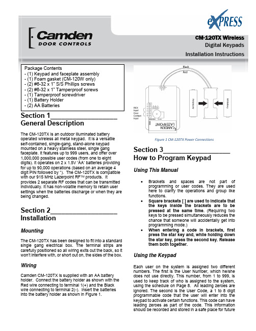
CM-120TX WirelessDigital KeypadsInstallation InstructionsSection 1__________________ General DescriptionThe CM-120TX is an outdoor illuminated battery operated wireless all metal keypad. It is a versatile self-contained, single-gang, stand-alone keypad mounted on a heavy stainless steel, single gang faceplate. It features up to 999 users, and offer over 1,000,000 possible user codes (from one to eightdigits). It operates on 2 x 1.5V ‘AA’ batteries providing for up to 90,000 operations (based on an average 4 digit PIN followed by *). The CM-120TX is compatible with our 915 MHz Lazerpoint RF TM products. Itprovides 2 separate RF codes that can be transmitted individually. It has non-volatile memory to retain user settings when the batteries discharge or when they are being changed.Section 2__________________ InstallationMountingThe CM-120TX has been designed to fit into a standard single gang electrical box. The terminal strips are carefully positioned so all wiring exits out the back, so it won’t interfere with, or short out on, the sides of the box.WiringCamden CM-120TX is supplied with an AA battery holder. Connect the battery holder as shown with the Red wire connecting to terminal 1(+) and the Black wire connecting to terminal 2(-). Insert the batteries into the battery holder as shown in Figure 1.Figure 1 CM-120TX Power ConnectionsSection 3__________________ How to Program KeypadUsing This Manual∙Brackets and spaces are not part of programming or user codes. They are used here to clarify the operations and group like functions.∙Square brackets [ ] are used to indicate that the keys inside the brackets are to be pressed at the same time. (Requiring two keys to be pressed simultaneously reduces the chance that someone will accidentally get into programming mode.)∙When entering a code in brackets, first press the star key and, while holding down the star key, press the second key. Release them both together.Using the KeypadEach user on the system is assigned two different numbers. The first is the User Number, which he/she does not use directly. This number, from 1 to 999, is used to keep track of who is assigned to the system, using the schedule on Page 8. All leading zeroes are ignored. The second is the User Code, a 1 to 8 digit programmable code that the user will enter into the keypad to activate certain functions. This code can have leading zeroes as part of the code. This information should be recorded and stored in a safe place for futurereference. The keypad can support a total of 999 users, from 1 to 999 (See chart on page 10).User number one belongs to the Master User and has a default user code of 1234. Note that the master user code is used for administration ONLY, and will not (normally) operate the wireless outputs. When a global disable is engaged (all users locked out), the master code will still operate wireless output one.User number two will toggle the global enable/disable function when prefixed by two or more pound (‘#’) keys. This allows lockout of all other codes (user two will still be able to operate the keypad normally, even when the global lockout is engaged). Therefore, user number two should be reserved for use by a manager. When entered without the prefixed ‘#’s, the code of user number 2 operates the keypad in the same way as the other users do.When using the keypad with variable-length user codes, it is necessary for the user to press the star (*) key after the User Code has been entered. This indicates the end of the code, and causes the keypad to attempt to validate the entered code. If the number entered is valid, the keypad will perform the programmed function (e.g., activate the relay).For example, to operate the keypad using the user code 4321 (which must be entered as a user code in programming mode first), enter 4321*. While the door is unlocked, or whatever job your unit is to perform, the green LED will blink at a slow rate. Note that the star key can be substituted with another digit of your choice. (See 0# Set Enter Key)Understanding the LEDsThe three Light Emitting Diodes (LED’s) above the keypad provide information on the status of the unit. NOTE: A ‘slow’ flash is once every two seconds and a ‘fast’ flash is once every second.GREEN LED:‘ON’ Solid:No errors, output isactive.‘FAST FLASHING’: Keypad is inprogramming mode. RED LED:‘ON’ Solid: Error condition.See chart at end ofthis manual.YELLOW LED:To meet ADA requirements, both a visual and audible key-press confirmation is provided (blinks on each key-press). This can be enabled or disabledduring programming. See the [*6] 0 # programming option for more details.Checking the Battery LevelThe Cm-120TX has a built-in battery gauge. Press and hold the any button for 5 seconds. The Green LED will flash and the buzzer will beep up to 5 times indicating the battery level.5 Beeps = Fully charged batteries1 Beep = Replace the batteriesThe CM-120TX will beep if the Low Battery Alarm(page 4) is enabled.SET-UP INSTRUCTIONS:Note:1. Keep careful track of User Codes and to whomthey are assigned, assigned outputs, etc. asyou program them, and keep the list in a safeplace.2. Press the buttons firmly.3. Whenever the * and any other character areincluded in brackets [* x], press the * firstand, while holding the * down, press theother key. Release both keys together. [*1] Enter Program Mode (First Step)Press * and 1 at the same time. Enter the Master Code (1234 is the factory default), then *. The green LED should now be rapidly flashing.The keypad will remain in program mode until no key is pressed for approximately 30 seconds. To exit programming mode quickly, press the special sequence –“ * # * ”.For example, [* 1] 1 2 3 4 * will put the keypad in program mode.[*1] Administration FunctionsSet Code Length - Function 1#Default: 0 (variable code length)When set to zero, user codes can vary from 1 to 8 characters, but must be terminated by pressing the “enter key”, which by default is ‘*’. When set from 1 to 8, all user codes must use the programmed length, but will not require termination by the programmed “enter key”.(User codes shorter than the maximum are still allowed, but the user must terminate it with the current “enter” key).For example, [*1] 1 # 4 * will set all user codes toa fixed 4-digit length.Set Enter Key - Function 0#Default: ‘*’If the code length has been left at 0 (see above), then use this feature to select the “enter” key used to terminate user code entry. The default setting is ‘*’, but it can be changed to any key on the keypad (select carefully).For example, [*1] 0 # # * will change the usercode enter key to ‘#’.Incorrect Code Count Alarm - Function 2#Default: 0 (disabled)When set to zero, the keypad will not alarm on entry of invalid codes. When set to a value between 1 and 20, the keypad will generate an alarm after the specified number of invalid codes have been entered, within two minutes.For example, [*1] 2 # 6 * will set the keypad to generate an alarm when 6 invalid user codes have been entered. NOTE: This setting also requires the “Incorrect code alarm Lockout” feature enabled. See 5# on page 4. Force Unique User Codes - Function 3#Default: 1 (Enabled)When set to zero, the keypad will accept any user code for each user. When set to one, during programming of new user codes, the keypad will check the desired code against all currently programmed users, and only accept the user code if it is unique. Attempting to program a code that is not unique will cause an error alarm, and the programming procedure must be restarted and a different code selected.NOTE: When enabling this mode (when previously disabled), it is recommended the administrator erase all settings back to factory defaults first, to ensure all user codes are unique. Failure to perform this step may leave duplicate user codes among those already learned, and result in unexpected operation.0 = disabled1 = enabledFor example, [*1] 3 # 0 * will dis able “Force Unique User C odes”.Backlight Control Enable/ Disable -Function 5#Default: 0 (disabled)Enable or disable backlight control on keypress. When enabled, the backlight will be OFF until the first keypress. It will remain on for 5 seconds after the last keypress. When disabled, the backlight will remain OFF.0 = disabled1 = enabledTo enable/disable Backlight Control mode:First, enter program mode. Then enter [*1], then 5#, then 0 to disable, or 1 to enable, then *.For example, [*1] 5 # 1 * will make the backlighting turn ON after the first key press. The backlighting will remain ON for 5 seconds after the last key press. User Two “Global Lockout” - Function 6#Default: 1 (Enabled)When enabled, user #2 (a manager, for instance) can lockout all other users by prefixing his code by two (or more) “#” keys. When a global lockout is engaged, no user code will activate the outputs, except user #1 & #2. Programming functions, and request to exit (REX) are not disabled. This can be used (for instance) to immediately control all access while changing selected user codes in case of a security problem, or for lockout over a weekend.To disable user two “global lockout” feature:First, enter program mode. Then enter [*1], then 6#, then 0 to disable, or 1 to enable, then *.0 = disabled1 = enabledFor example [*1] 6 # 0 * will disable user #2’s ability to engage a global lockout.Note: When user number #2’s key code is prefixed with two or more ‘#’s, the “Global User Enable/ Disable” flag will be toggled.Channel Output Mode - Function 7#Default: 0 (Channel 1 Only)This control allows the installer to select the channel output mode. Chosing the default (0) means that a valid code activates Channel 1 only.Setting the Channel Output Mode to “1” will allocate the first 499 user numbers (memory addresses) to Channel 1, and the remaining 500 user numbers to Channel 2. To choose the Relay Output mode:First, enter program mode. Then enter [*1], then 7#, then 0 for Relay 1 only, 1 for split output, or 2 for both relays sequenced, then *.0 = Channel 11 = 1 - 499 = Channel 1, 500 – 999 = Channel 2For example [*1] 7 # 1 * will allocate any user number from 1 – 499 to Channel 1, and any user number from 500 – 999 to Channel 2.[*2] Add/Change/Delete UsersTo add or change a user:First, enter program mode (see First Step above), then enter [*2], then the user number you wish to add or change (from 1 to 999 inclusive) followed by #. Finally, enter the new User Code (up to 8 digits), followed by *, then the new User Code again (for verification), followed by *. User Codes may only contain digits 0 through 9 (* and # may not be used as part of the code, except when programmed as the “enter” key). Example: [*2] 44 # 2125 * 2125 * will assign a user number of 44 and a user code of 2125.To delete a user code:First, enter program mode. Then enter [*2], then the user number you wish to delete (from 2 to 999, inclusive), then press #, then *, then *.For example, [*2] 75 # * * will delete the user code and all assignments for user number 75.PLEASE NOTE: The Master Code cannot be deleted but it may be changed.Example: [*2] 1 # 38714 * 38714 * will change the Master Code to 38714. If you change it, don’t forget it. [*3] Time Delay/Duration FunctionsDoor Prop open Alarm Delay - Function 2#Default: DisabledSets the delay (1 to 255 seconds) before open door contacts are considered an alarm condition. (NOTE: Door contacts are required for this feature.) To program the door open alarm delay:First, enter program mode. Then enter [*3], then 2#, then the delay time in seconds (0=disabled), then *. For example, [*3] 2 # 30 * will set the door open alarm delay to 30 seconds.NOTE: To turn this feature on/off, see section [*4] 3# Door Prop Open Alarm on the next page.[*4] Alarm Control FunctionsIncorrect code alarm - Function 0# Default: 0 (Disabled)Use to control how the “Incorrect code alarm” is annunciated.0 = disabled1 = buzzerIf the “Incorrect code alarm” is enabled, and triggered, a valid code is required to reset.To program how the “incorrect code alarm” condition is annunciated:First, enter program mode. Then enter [*4], then 0#, then the annunciation code, then *.For example, [*4] 0 # 1 * will configure the keypad to indicate entry of the programmed count of invalid codes on the buzzer only.Low Battery Alarm - Function 1#Default: 1 (Enabled)Enable or disable the “Low battery alarm”.0 = disabled1 = buzzerTo disable the “low battery alarm”:First, enter program mode. (See “First Step” above) Enter [*4], then 1#, then the annunciation code, then *. For example, [*4] 1# 0* will configure the keypad not to annunciate the low battery condition.Stuck key alarm - Function 2#Default: 0 (Disabled)Enable or disable the “Stuck key alarm”.0 = disabled1 = enableThe “Stuck key” alarm will a ctivate the buzzer after 15 seconds (factory set delay) of the key being held continuously, and reset as soon as the key is released (or after 10 seconds, whichever occurs first)To en able the “stuck key alarm”:First, enter program mode. Then enter [*4], then 2#, then (0 or 1), then *.For example, [*4] 2 # 1 * will configure the keypad to activate the stuck key buzzer.Door Prop open Alarm - Function 3#Default: 0 (Disabled)Use to control how the “Door prop open alarm” is annunciated.0 = disabled1 = buzzerTo program how the “Door Prop open alarm” condition is annunciated:First, enter program mode. Then enter [*4], then 3#, then the annunciation code, then *.For example, [*4] 3 # 1 * will annunciate the buzzer during the alarm.NOTE 1:this feature requires the use of the door contact input.NOTE 2: The alarm will sound continuously until reset. To reset, enter valid code.NOTE 3: To set Delay Time, see [*3] 2# on Page 4. Incorrect code alarm lockout - Function 5# Default: 0 (Disabled)Use to configure the incorrect code alarm lockout.0 = disabled1 = enabledTo program:First, enter program mode. Then enter [*4], then 5#, then the enable/disable code, then *.For example, [*4] 5 # 1 * will configure the keypad to lockout for 2 minutes (factory set lockout duration), after the incorrect code count alarm limit is reached. During the lockout period, all keypad entry (including correct codes) is ignored.There is an automatic reset after 2 minutes.(See 2# on Page 3 of manual for setting code count) Door Forced open Alarm - Function 6# Default: 0 (Disabled)Use to control how the “Door forced open alarm” is annunciated.0 = disabled1 = buzzerTo program how the “Door forced open alarm” condition is annunciated:First, enter program mode. Then enter [*4], then 6#, then the annunciation code, then *.For example, [*4] 6 # 1 * will configure the keypad to sound an alarm if the door is forced open (without entering a valid code).NOTE 1:this feature requires the use of the door contact input.NOTE 2: The alarm will sound continuously until reset. [*6] Annunciation Control Functions Yellow LED Enable - Function 0#Default: 1 (Enabled) Enable or disable the yellow LED. When enabled, the yellow LED illuminates when any key is pressed.0 = disabled1 = enabledTo disable the yellow LED:First, enter program mode. Then enter [*6], then 0 #, then 0 to disable, or 1 to enable, then *.For example, [*6] 0 # 0 * will disable yellow LED illumination.Buzzer Enable / Disable - Function 1# Default: 1 (Enabled)Enable or disable the buzzer. When disabled, the buzzer will not sound for any condition0 = disabled1 = enabledTo disable the buzzer:First, enter program mode. Then enter [*6], then 1#, then 0 to disable, or 1 to enable, then *.For example, [*6] 1 # 0 * will disable the buzzer for all conditions.Correct Code Audio Tone - Function 2# Default: 0 (Disabled)Enable or disable the audio tone annunciating correct code entry. When enabled, a single 2 tone beep will sound when a correct code has been entered. In the case of toggled mode, the audio tone will last for 8 seconds (hard-coded) when a correct code toggles relay one ON; the audio tone will be a single two-tone beep, “do-ray”, when a correct code toggles relay one OFF.0 = disabled1 = enabledTo enable the audio tone on correct code entry: First, enter program mode. Then enter [*6], then 2#, then (0 to disable, or 1 to enable), then *.For example, [*6] 2 # 1 * will enable the audio tone on correct code entry.Incorrect Code Audio Tone - Function 3# Default: 1 (Enabled)Enable or disable the audio tone annunciating correct code entry. When enabled, an audio tone will sound when any incorrect code has been entered, for the duration that the red LED is illuminated.0 = disabled1 = enabledTo disable the audio tone on incorrect code entry:First, enter program mode. Then enter [*6], then 3#, then 0 to disable, or 1 to enable, then *.For example, [*6] 3 # 0 * will disable the audio tone on incorrect code entry.Request to Exit Audio Enable/Disable - Function 5#Default: 0 (Disabled)Enable or disable audio annunciation for Channel #1 when a Request to Exit signal is input. When enabled, if Channel 1 is triggered by REX input, a looped tone (do-ray) will be annunciated for the duration that Relay #1 is energized. In the case of Toggled mode, the annunciation will last for 8 seconds (hard-coded). In the case of entering into Unlocked Mode (REX input held for more than 15 seconds), 4 beeps will sound after the looped two-tone annunciation. A si ngle (“Ray-Do”) tone will sound when exiting Unlock Mode.0 = disabled1 = enabledTo enable/disable REX Audio Annunciation:First, enter program mode. Then enter [*6], then 5#, then 0 to disable, or 1 to enable, then *.For example, [*6] 5 # 1 * will enable the audio annunciation for REX input.FACTORY DEFAULT SETTINGSIf the settings have not been changed after shipment, or if they have been reset, they are as follows:o Master User # 1 - Code is 1234.o Main Channel = 3 seco Secondary Channel = programmable.o Yellow LED enabled.Reset to Factory DefaultsReset the Master Code:While holding the # and * down together for aprox. 4 secs, power up the keypad. There will be 4 beeps and all LED’s will flash. The keypad will immediately move into the battery life indicator. It will beep up to 5 times and the green LED will flash.Reset the keypad to factory defaults:While holding down the # and * for approx. 10 seconds. Power up the keypad. There will be the initial 4 beeps at the 4 second point, indicating the Master Code is reset (1234), followed by the battery test beeps (up to 5), then followed by 8 beeps indicating the keypad has been reset to factory defaults.[*9] Erase Keypad Memory/Reset ALL to FactoryForce factory default settings (use with caution)This is used when most or all of the programming has to be changed, as when a keypad has been moved to a new location. To reset to factory defaults.First, enter program mode. Then enter [*9], then re-enter the master keycode, then *.For example, [*9] 1 2 3 4 * will immediately and permanently clear the entire memory (assuming the master keycode has not been changed from the factory default. Once this function has been executed, there is NO WAY to restore the previous state.Section 4 _________________ Technical DataModel CM-120TXIllumination No / YesSize 2 ¾” x 4 ½” x ¾”69.85mm x 114.30mm x19.05mmMounting 2 x #6-32 machine securityscrewsTemperature -40° - +185°F (-40° - +85°C) Operating voltage 2 x AA Alkaline Batteries Battery Life 90,000 OperationsBased on a 4 digit user code Capacity 999 User codesLength Up to 8 digits (10 millionpossible codes)Response time 0.3 secondsInputs 1 x REX input1 x Door Contact input Output RF Only,2 ChannelsChannel 1 assigned to users1 - 499Channel 2 assigned to users500 - 999Section 5_________________WarrantyCamden Door Controls guarantees the CM-120TX to be free from manufacturing defects for 3 years from date of sale. If during the first 3 years the CM120TX fails to perform correctly, it may be returned to our factory where it will be repaired or replaced (at our discretion) without charge. Except as stated herein, Camden extends no warranties expressed or implied regarding function, performance or service.Troubleshooting Tipso If you make an input error (e.g. if you enter anon-existent User Code) and press the star key, the red LED will light. Simply start over.o If you make an input error and have not yetentered *, just wait 5 seconds, and the command memory will be cleared automatically. Start again. You will not increment the error count.o The “Lockout -on-#-errors” feature is disabled by default. This will prevent the keypad from hanging up if anyone plays with the keypad in certain applications.o Do not make the mistake of thinking you have to 'clear' the red light if you make an error. Just re-enter the correct number. The red LED will clear automatically with the first key you press.o Be sure you are pressing the buttons firmly. The yellow LED should come on and an audio tone should sound with each key pressed, unless these features have been disabled.Questions?Visit us online at Call us toll-free at 1-877-CAMDEN9 or (905)366-3377File: CM-120TX_NF_Man_Rev1.docx Firmware Version: 1.08Revised: December 16, 2014Part No.: 40-82B166Toll Free: 1.877.226.3369 5502 Timberlea Blvd.,Mississauga, ON Canada L4W 2T7。
超高清4K-6M40转接板TLC4K.M60板卡规格书
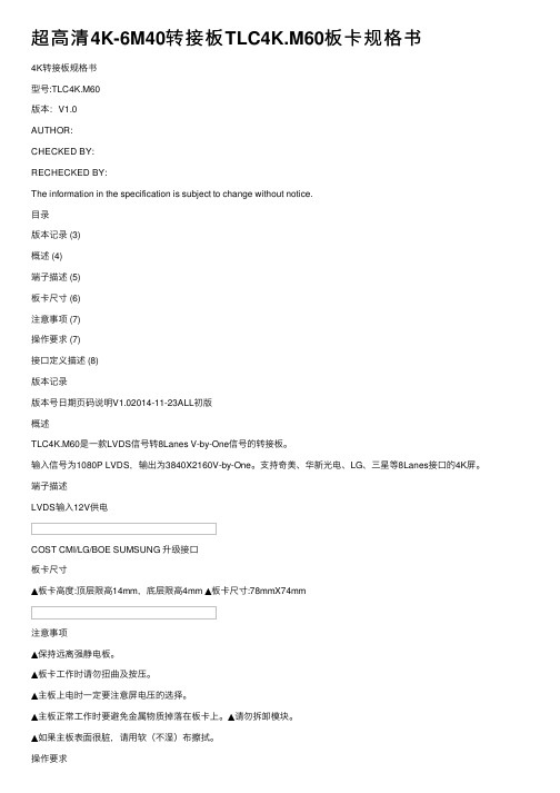
超⾼清4K-6M40转接板TLC4K.M60板卡规格书4K转接板规格书型号:TLC4K.M60版本:V1.0AUTHOR:CHECKED BY:RECHECKED BY:The information in the specification is subject to change without notice.⽬录版本记录 (3)概述 (4)端⼦描述 (5)板卡尺⼨ (6)注意事项 (7)操作要求 (7)接⼝定义描述 (8)版本记录版本号⽇期页码说明V1.02014-11-23ALL初版概述TLC4K.M60是⼀款LVDS信号转8Lanes V-by-One信号的转接板。
输⼊信号为1080P LVDS,输出为3840X2160V-by-One。
⽀持奇美、华新光电、LG、三星等8Lanes接⼝的4K屏。
端⼦描述LVDS输⼊12V供电COST CMI/LG/BOE SUMSUNG 升级接⼝板卡尺⼨▲板卡⾼度:顶层限⾼14mm,底层限⾼4mm ▲板卡尺⼨:78mmX74mm注意事项▲保持远离强静电板。
▲板卡⼯作时请勿扭曲及按压。
▲主板上电时⼀定要注意屏电压的选择。
▲主板正常⼯作时要避免⾦属物质掉落在板卡上。
▲请勿拆卸模块。
▲如果主板表⾯很脏,请⽤软(不湿)布擦拭。
操作要求▲相对湿度:≤80%.▲存储温度:-10~+60°C.▲⼯作温度:0~+40°C.接⼝定义描述UJ6(2×20PIN/2.0):LVDS输出接⼝NO.SYMBOL DESCRIPTION1VSEL Power Supplyfor Panel2VSEL Power Supplyfor Panel3VSEL Power Supplyfor Panel4GND Ground5GND Ground6GND Ground7RXE0-LVDS EVEN0-Signal8RXE0+LVDS EVEN0+Signal9RXE1-LVDS EVEN1-Signal10RXE1+LVDS EVEN1+Signal11RXE2-LVDS EVEN2-Signal12RXE2+LVDS EVEN2+Signal13GND Ground14GND Ground15RXEC-LVDS EVEN Clock-Signal 16RXEC+LVDS EVEN Clock+Signal 17RXE3-LVDS EVEN3-Signal 18RXE3+LVDS EVEN3+Signal19RXO0-LVDS ODD0-Signal20RXO0+LVDS ODD0+Signal21RXO1-LVDS ODD1-Signal22RXO1+LVDS ODD1+Signal23RXO2-LVDS ODD2-Signal24RXO2+LVDS ODD2+Signal25GND Ground26GND Ground27RXOC-LVDS ODD Clock-Signal 28RXOC+LVDS ODD Clock+Signal 29RXO3-LVDS ODD3-Signal 30RXO3+LVDS ODD3+Signal31GND Ground32GND Ground33NC-343D/ON Logic Level Control(Default For High Level) 35M_SCL I2C SCL 36M_SDA I2C SDA37RXE4-LVDS EVEN4-Signal38RXE4+LVDS EVEN4+Signal39RXO4-LVDS ODD4-Signal40RXO4+LVDS ODD4+SignalCON4(4PIN/2.54):外置USB接⼝NO.SYMBOL DESCRIPTION1GND Ground2GND Ground312V+12V POWER512V+12V POWERUCON01(4PIN/2.0):DEBUG接⼝NO.SYMBOL DESCRIPTION1NC-2GND Ground3RX SCL5TX SDAJ2002可直连华新光电8Lanes V-by-One屏接⼝J2003可直连奇美、LG、京东⽅8Lanes V-by-One屏接⼝J2004可直连三星8Lanes V-by-One屏接⼝。
乐华MST 6M20S 120Hz转接板升级指导说明
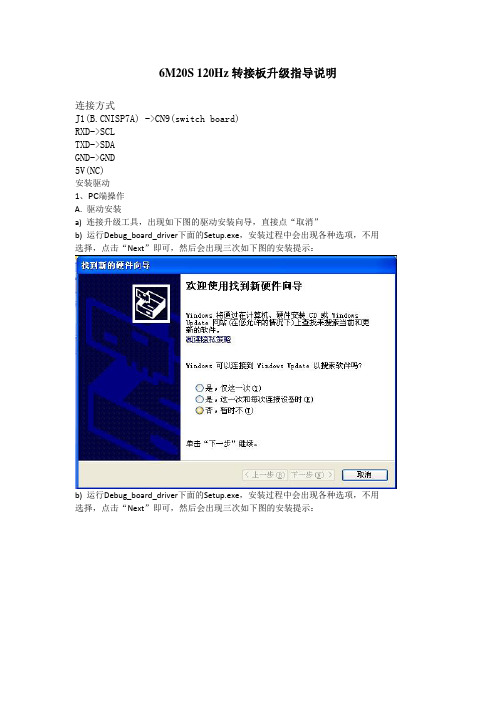
6M20S 120Hz转接板升级指导说明
连接方式
J1(ISP7A) ->CN9(switch board)
RXD->SCL
TXD->SDA
GND->GND
5V(NC)
安装驱动
1、PC端操作
A. 驱动安装
a) 连接升级工具,出现如下图的驱动安装向导,直接点“取消”
b) 运行Debug_board_driver下面的Setup.exe,安装过程中会出现各种选项,不用
选择,点击“Next”即可,然后会出现三次如下图的安装提示:
b) 运行Debug_board_driver下面的Setup.exe,安装过程中会出现各种选项,不用
选择,点击“Next”即可,然后会出现三次如下图的安装提示:
c) 请点击“仍然继续”,最后提示安装成功:
d) 打开“设备管理器”,找到如下图红色方框内的设备,说明驱动安装正确。
升级工具软件:ISP_Tool_V4.4.9.5.exe或者以下版本
主界面
第一次使用的操作事项:
第一次使用ISP工具,要先点击CONFIG按钮
设置ISP和SERIAL DEBUG的I2C地址
设置好后软件会自动保存设置选项,再使用不用设置CONFIG。
每次升级使用操作事项:
【1】先点击CONNECT按钮
连接不成功
连接成功
【2】后点击READ按钮
选择文件
【3】最后点击AUTO按钮
点击RUN按钮开始升级
升级成功。
华为OSN3500 光传输设备各业务板件详细描述

华为OSN3500 光传输设备各业务板件详细描述:成品板-OptiX OSN3500-SSN2PQ1A02-63xE1业务处理板(E1/75ohm)成品板-OptiX OSN3500-SSN2PQ1B02-63xE1业务处理板(E1/120ohm)制成板-OSN3500-SSN1D75S-32xE1/T1电接口倒换出线板(75欧姆)-1x1拼板制成板-OSN3500-SSN1D12S-32xE1/T1电接口倒换出线板(120欧姆)-1x1拼板成品板-OptiX OSN 3500-SSN1SL4A20-STM-4光接口板(S-4.1,LC)成品板-Optix OSN 3500-SSN1SL4A21-STM-4光接口板(L-4.1,LC)成品板-OptiX OSN 3500-SSN1SL4A22-STM-4光接口板(L-4.2,LC)成品板-OptiX OSN 3500-SSN1SL4A23-STM-4光接口板(Ve-4.2,LC)成品板-OSN3500-SSN1SL1A20-STM-1光接口板(S-1.1,LC)成品板-OSN3500-SSN1SL1A21-STM-1光接口板(L-1.1,LC)成品板-OSN3500-SSN1SL1A22-STM-1光接口板(L-1.2,LC)成品板-OptiX OSN 3500-SSN3SL1602-STM-16光接口板(L-16.2JE,LC)成品板-OptiX OSN 3500-SSN3SL1603-STM-16光接口板(V-16.2Je,LC)成品板-OptiX OSN 3500-SSN3SL1604-STM-16光接口板(U-16.2,LC)成品板-OSN3500-SSN3SL16A06-STM-16 光接口板(I-16,LC)成品板-OSN3500-SSN3SL16A07-STM-16 光接口板(S-16.1,LC)成品板-OSN3500-SSN3SL16A08-STM-16 光接口板(L-16.1,LC)成品板-OSN3500-SSN3SL16A09-STM-16 光接口板(L-16.2,LC)成品板-OptiX OSN3500-SSN1SLQ1A22-4xSTM-1 光接口板(S-1.1,LC)成品板-OptiX OSN3500-SSN1SLQ1A23-4xSTM-1 光接口板(L-1.1,LC)成品板-OptiX OSN3500-SSN1SLQ1A24-4xSTM-1 光接口板(L-1.2,LC)成品板-OptiX OSN3500-SSN1SLQ1A25-4xSTM-1 光接口板(Ie-1,LC,多模)成品板-OSN3500-SSN2SLO110-8xSTM-1光接口板(S-1.1,LC)成品板-OSN3500-SSN2SLO111-8xSTM-1光接口板(L-1.1,LC)成品板-OSN3500-SSN2SLO112-8xSTM-1光接口板(L-1.2,LC)成品板-OSN3500-SSN2SLO113-8xSTM-1光接口板(Ve-1.2,LC)成品板-OSN3500-SSN2SLO114-8xSTM-1光接口板(I-1,LC)成品板-OptiX OSN 3500-SSN1SLQ4A20-4xSTM-4 光接口板(S-4.1,LC)成品板-OptiX OSN 3500-SSN1SLQ4A21-4xSTM-4 光接口板(L-4.1,LC)成品板-OptiX OSN 3500-SSN1SLQ4A22-4xSTM-4 光接口板(L-4.2,LC)OSN3500-SSN1EGS410-四路交换式千兆以太网处理板(1000BASE-SX,850-LC)OSN3500-SSN1EGS411-四路交换式千兆以太网处理板(1000BASE-LX,1310-LC) OSN3500-SSN1EGS412-四路交换式千兆以太网处理板(1000BASE-VX,1310-LC) OSN3500-SSN1EGS413-四路交换式千兆以太网处理板(1000BASE-ZX,1550-LC) OSN3500-SSN1EGS414-四路交换式千兆以太网处理板(1000BaseT,RJ45。
- 1、下载文档前请自行甄别文档内容的完整性,平台不提供额外的编辑、内容补充、找答案等附加服务。
- 2、"仅部分预览"的文档,不可在线预览部分如存在完整性等问题,可反馈申请退款(可完整预览的文档不适用该条件!)。
- 3、如文档侵犯您的权益,请联系客服反馈,我们会尽快为您处理(人工客服工作时间:9:00-18:30)。
LCD board specification for KST6MX0.A2
P r o d u c t S p e c i f i c a t i o n V i d e o C o n v e r t e r b o a r d M o d e l:K S T6M X0.A2
Author:邓庆春
Review:
Version: V1.1
LCD board specification for KST6MX0.A2 CONTENTS
LCD board specification for KST6MX0.A2 REVISION HISTORY
SHEN ZHEN TECON CRYSTAL DISPLAY TECHNOLOGY CO.,LIMITED 4
1 GENERAL DESCRIPTION
▲
T6M30 is a support for MEMC and the design of 3D display processing.
2 FEATURES
3 INTERFACE FUNCTION DESCRIPTION
SHEN ZHEN TECON CRYSTAL DISPLAY TECHNOLOGY CO.,LIMITED 5
4 GENERAL PRECAUTIONS
▲
Keep the board away from strong electrostatic.
▲
Disconnect main power if power of panel is incorrect,otherwise you would destroyed the LCD module.
▲
Avoid dropping metal in the board while it is working. ▲
Do not push or pull the connector while the board is working. ▲
Do not disassemble the module.
▲
If the surface of the main board is dirty, clean it with soft(not wet) cloth.
SHEN ZHEN TECON CRYSTAL DISPLAY TECHNOLOGY CO.,LIMITED 6
5 OPERATION REQUIREMENTS
▲
Relative humidity:≤ 80%. ▲
Storage temperature: -10~+60 °C. ▲
Operation temperature: -10~+40 °C.
6 INTERFACE DEFINITION
7
8
SHEN ZHEN TECON CRYSTAL DISPLAY TECHNOLOGY CO.,LIMITED 9
SHEN ZHEN TECON CRYSTAL DISPLAY TECHNOLOGY CO.,LIMITED 10
注释:本规格书依据目前现有产品规格描述,由于产品存在不断改进的需求,因此我们对相 关参数细节保留修改的权力,不再另行通知!。