HVP 40 高压测试棒说明书
高压注射器产品技术要求juhongkang
高压注射器产品技术要求juhongkang高压注射器适用范围:用于磁共振(MRI)增强检查时对比剂的注入。
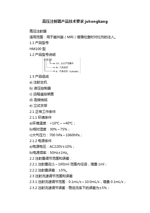
1.1产品型号HM100型1.2产品型号说明1.3产品组成a) 注射主机b) 液压控制器c) 远程遥控装置d) 连接线缆e) 立式支架2.1 正常工作条件2.1.1环境条件a)环境温度:+10℃~+40℃;b)相对湿度:30%~75%;c)大气压力:700 hPa~1060hPa;2.1.2电源条件a)电源电压:AC220V±10%;b)电源频率:50Hz±1Hz。
2.2注射量调节范围和误差:2.2.1注射量在(1~100)ml范围内任选,增量1ml;2.2.2注射量误差:±5%。
2.3注射流速调节范围和误差2.3.1注射流速调节范围:0.1mL/s~10.0mL/s,增量0.1mL/s;2.3.2注射流速调节误差:稳定流率下的误差为±5%;2.3.3流速转换时间和注射总量误差当一个注射程序项下有多个注射流速,且相邻两个阶段的注射流速之间的差≥2.5mL/s时,其注射流速转换的时间应不超过3s;且注射总量误差应不大于该注射程序设定的注射总量的±5%。
2.4注射压力范围和误差2.4.1高压注射器的压力范围可在40psi~300psi范围内任选,增量1psi,误差:±10%;2.4.2在注射过程中,当压力达到极限值时,系统自动暂停注射。
2.5噪声整机运行噪声应不大于A计权70dB。
2.6注射安全保护功能2.6.1在注射器针筒处于向上位置时,设备处于程序锁死状态,不能进行注射,只有向左或向右倾斜到位时才能进行注射;2.6.2高压注射器机头可在其左(右)极限位置绕其旋转轴向右(左)旋转大于270°。
当高压注射器机头达到左(右)极限位置时,高压注射器才能进行注射;2.6.3注射过程中,点击触摸屏的任何部位,应暂停注射。
2.7高压注射器远程遥控装置远程遥控装置的触摸屏显示器应灵敏,点击触摸屏时,触摸屏应有迅速的响应。
Extech CT40 用户手册说明书
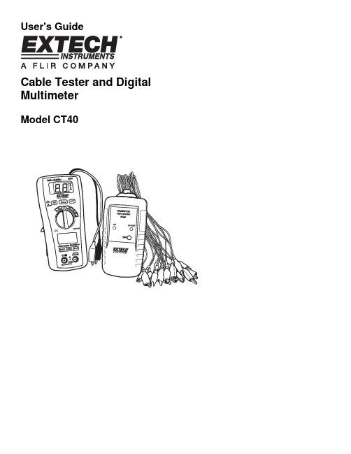
User's GuideCable Tester and Digital MultimeterModel CT40CT40 V1.3 09/092 IntroductionCongratulations on your purchase of the Extech CT40. This meter is shipped fully tested and calibrated and, with proper use, will provide years of reliable service. The CT40 is a cable tester which uses a transmitter/receiver to allow for wire identification of an individual core to the end of a multi-core cable .The meter’s digital multimeter functions provides for easy measurement of AC/DC Voltage, AC/DC Current, Resistance, Continuity and Diode check.SafetyInternational Safety SymbolsThis symbol, adjacent to another symbol or terminal, indicates the user must refer to the manual for further information.This symbol, adjacent to a terminal, indicates that, under normal use, hazardous voltages may be presentDouble insulationSafety Notes• Do not exceed the maximum allowable input range of any function.• Set the function switch OFF when the meter is not in use.• Remove the battery if meter is to be stored for longer than 60 days.Warnings• Set function switch to the appropriate position before measuring.• Do not measure current on a circuit whose voltage exceeds 600V.• When changing ranges always disconnect the test leads from the circuit under test. Cautions• Improper use of this meter can cause damage, shock, injury or death. Read and understand this user manual before operating the meter.• Always remove the test leads before replacing the battery.• Inspect the condition of the test leads and the meter itself for any damage before operating the meter. Repair or replace any damage before use.• Use great care when making measurements if the voltages are greater than 25VAC rms or 35VDC. These voltages are considered a shock hazard.• Voltage checks on electrical outlets can be difficult and misleading because of the uncertainty of connection to the recessed electrical contacts. Other means should be used to ensure that the terminals are not "live".• If the equipment is used in a manner not specified by the manufacturer, the protectionprovided by the equipment may be impaired.CT40 V1.3 09/093 Meter Description1.Low Battery Indicator -Receiver 2.Receiver Alligator Test Leads 3.Operation Indicator -Receiver 4.On/Off Switch -Receiver 5.Hold Switch – Digital Multimeter Mode 6.DMM Input Jacks 7.Max Button – Digital Multimeter Mode 8.Mode Button – Digital Multimeter Mode 9. LCD Display – Multimeter Mode 10. Rotary Switch – Multimeter Mode11. ID Test Button –Continuity Beep Test12. V Check Button – Cable Voltage Check13. LCD Display for Cable Identifier Function14. Operation Indicator- Transmitter15. Low Battery Indicator –Transmitter16. On/Off Switch – Transmitter17. Transmitter Alligator Test Leads – CH1-16LCD display descriptions1.Cable ID Number Display 2.Low bat LED 3.OP operation LED4. Autorange Indicator5. Diode Test6. Continuity7. Display Hold8. Max9. Low Battery Indicator 10. Units11. DMM Digit Display12. AC/DC Indicators2OperationTransmitter and Receiver Cable Tester Operation1. Press down the receiver’s ON/OFF switch. The upper blue display will indicate “00”and the OP LED should light.2. Press down the transmitter’s ON switch. The OP LED will flash.3. Connect one of the transmitter’s alligator clips (CH1 to CH16) to each core (wire) ofthe cable under test.4. Connect the transmitter’s “COM” reference lead (black alligator) to a known commonfor all cables, such as ground or cable sheath.5. Connect the receiver’s “COM terminal” (black alligator) to the common.6. Touch the receiver’s “input terminal” (red alligator) test lead to one core of the cableunder test.7. The number of the wire selected is indicated on the display of the receiver (1-16).CAUTION: Do not apply over 50V (AC or DCV) to test leads of transmitter or receiver.This could result in permanent damage to the meter.Continuity Beep Test1. Press the ID TEST button down.2. Connect the receiver’s red and black alligator clips to each end of a wire.3. If there is continuity (resistance is less than the continuity threshold) there will be anaudible tone.Voltage CheckV check button down.1. Pressthe2. Connect both of the receiver’s alligator clips to each end of the cable under test.3. If the display indicates “UU” then voltage is present on the cable. Locate and removethe voltage source before proceeding with cable testing.CT40 V1.3 09/094Digital Multimeter FunctionsAC/DC Voltage Measurements1. Insert the black test lead into the negative COM terminal and the red test lead into thepositive V terminal.2. Set the rotary function switch to VAC or VDC position.3. Connect the test leads in parallel to the circuit under test.4. Read the voltage measurement on the LCD display.CAUTION: Do not measure AC/ DC voltages if a motor on the circuit is being switchedON or OFF. Large voltage surges may occur that can damage the meter.AC/DC Current Measurements1. Set the function switch to the µA/mA position.2. Insert the black test lead into the negative COM terminal and the red test lead into thepositive µA/mA terminal.3. For current measurements up to 2000µA DC/AC, set the function switch to the mApositionMODE button to indicate “DC” / “AC” on the display.the4. Press5. Connect the meter in series with the circuit under test, the black test probe tip to thenegative side of the circuit and the red test probe tip to the positive side of the circuit.6. Apply power to the circuit.7. Read the current in the displayResistance Measurements1. Set the function switch to the Ω position.2. Insert the black test lead into the negative COM terminal and the red test lead into thepositive Ω terminal.3. Touch the test probe tips across the circuit or part under test. It is best to disconnectone side of the part under test so the rest of the circuit will not interfere with theresistance reading.4. Read the resistance in the displayWARNING: To avoid electric shock, disconnect power to the unit under test and discharge all capacitors before taking any resistance measurements.CT40 V1.3 09/095CT40 V1.3 09/096 Continuity Check WARNING: To avoid electric shock, never measure continuity on circuits or wires thathave voltage on them.1.2. Insert the black lead banana plug into the negative (-) jack (COM) and the red testlead banana plug into the positive (+) jack (Ω).3. Press the MODE4. Touch the test probe tips to the circuit or wire you wish to check.5.If the resistance is less than the continuity threshold, the audible signal will sound. The display will also show the actual resistance. DIODE TESTWARNING: To avoid electric shock, do not test any diode that has voltage on it.1. 2. Press the MODE 3. Insert the black test lead banana plug into the negative (-) jack (COM) and the redtest lead banana plug into the positive (+) jack (Ω).4. Touch the test probe tips to the diode or semiconductor junction you wish to test. Notethe meter reading.5. Reverse the probe polarity by switching probe position. Note this reading.6. The diode or junction can be evaluated as follows:A. If one reading shows a value and the other reading shows OL, the diode is good.B. If both readings show OL, the device is open.C. If both readings are very small or 0, the device is shorted.NOTE: The value indicated in the display during the diode check is the forward voltage.MAX Hold Function1.Press the MAX Hold Button. The meter continues taking measurements but the display shows only the highest (MAX) reading recorded. 2.Press the Max Hold Button again to return to normal operation.Data Hold Function1.Press the Data Hold Button. The HOLD indicator will appear. The hold function freezes the reading in the display. 2.Press the Data Hold Button again to return to normal operation.Auto Power OFF FunctionThe auto off feature will turn the meter off after 15 minutes.CT40 V1.3 09/09 7Support line (781) 890-7440TechnicalSupport:Extension200;E-mail:******************Repair&Returns:Extension210;E-mail:*****************Product specifications subject to change without noticeFor the latest version of this User Guide, Software updates, and otherup-to-the-minute product information, visit our website: Extech Instruments Corporation, 285 Bear Hill Road, Waltham, MA 02451 MaintenanceREPLACING THE FUSES WARNING : To avoid electric shock, disconnect the test leads from any source of voltage before removing the fuse cover.1.Disconnect the test leads from the meter. 2.Remove the battery cover (two “B” screws) and the battery. 3.Remove the four “A” screws securing the rear cover. 4.Lift the center circuit board straight up from the connectors to gain access to the fuse holders 5.Gently remove the old fuse and install the new fuse into the holder. 6.Always use a fuse of the proper size and value (0.2A/250V fast blow for the 200mA range).Replace and secure the rear cover, battery and battery cover. 7.Align the center board with the connectors and gently press into place. 8. Replace and secure the rear cover, battery and battery cover. WARNING : To avoid electric shock, do not operate your meter until the fuse cover is in place and fastened securely.BATTERY INSTALLATION WARNING : To avoid electric shock, disconnect the test leads from any source of voltage before removing the battery cover.1.When the “Low Battery Indicator” is lit on the Transmitter or the Receiver it is necessary to replace the battery. 2.Turn power off and disconnect the test leads from the meter. 3.Open the rear battery cover by removing the screw. 4.Insert the battery into battery holder, observing the correct polarity. 5. Put the battery cover back in place. Secure with the screw. WARNING: To avoid electric shock, do not operate the meter until the battery cover is in place and fastened securely.Calibration and Repair ServicesExtech offers repair and calibration services for the products we sell. Extech also provides NIST certification for most products. Call the Customer Care Department for information on calibration services available for this product. Extech recommends that annual calibrations be performed to verify meter performance and accuracy.SpecificationsMax input voltage 600V AC/DCDiode Test Test current 1mA max., open circuit voltage of 1.5VtypicalContinuity Check Audible threshold between 15Ω and 200ΩDisplay 2000 count 3 -1/2 digit LCDOver range indication LCD displays “OL”Polarity Minus (-) sign for negative polarity.Low Battery Indication “BAT” symbol indicates low battery condition.Input Impedance >7.5MΩ (VDC & VAC)AC Response Average respondingACV Bandwidth 50Hz to60HzAuto Power Off 15 minutes (approximately)Fuse mA, µA ranges; 0.2A/250V fast acting FuseBatteries 9V battery and two “AAA” batteriesOperating Temperature 32°F to 104°F (0°C to 40°C)Storage Temperature 14°F to 122°F (-10°C to 50°C)Weight 10.8 oz (308g)Size 6.3x2.9x1.7”, (162x74.5x44.0mm)Standards IEC61010-1 CAT III-600V Pollution degree II, CEApprovedTransmitter SpecificationsDisplay Two red LED lampsAlligators 17Croc clips-red*16, black*1Cable resistance 30K Ohm maxbattery Power 9VPower current 1.8mAOperating temperature 0°C to 40°C (32°F to 104°f)Storage temperature –10°C to 50°C (14F to 122°F)Receiver SpecificationsDisplay Two digit blue LED displayAlligators 2 Croc clips-red*1, black*1Power 9V batteryPower current 23mAOperating temperature 0°C to 40°C (32°F to 104°F)Storage temperature –10°C to 50°C (14°F to 122°F)Continuity test Audible threshold between 15Ω and 1000ΩCable voltage check 5V to 16V DCCT40 V1.3 09/098Multimeter SpecificationsFunction Range Accuracy DC Voltage 200mV, ±(0.5% rdg + 3d)2.000V, 20.00V, ±(1.0% rdg + 3d)200.0V, 600V ±(1.0% rdg + 3d)AC Voltage 50-60Hz 2.000V, 20.00V ±(1.0% rdg + 5d) 200.0V, 600V ±(1.5% rdg + 10d)DC Current 200.0µA, 2000µA ±(1.5% rdg + 3d)20.00mA, 200.0mA ±(2.0% rdg + 3d) AC Current 200.0µA, 2000µA ±(1.8% rdg + 8d)20.00mA, 200.0mA ±(2.5% rdg + 8d)Resistance200.0Ω±(0.8% rdg + 5d) 2.000kΩ, 20.00kΩ, 200.0kΩ±(1.2% rdg + 3d)2.000MΩ±(2.0% rdg + 5d)20.00MΩ±(5.0% rdg + 8d)WarrantyEXTECH INSTRUMENTS CORPORATION(A FLIR COMPANY) warrants this instrument to be free of defects in parts and workmanship for one year from date of shipment (a six month limited warranty applies to sensors and cables). If it should become necessary to return the instrument for service during or beyond the warranty period, contact the Customer Service Department at (781) 890-7440 ext. 210 for authorization or visit our website for contact information. A Return Authorization (RA) number must be issued before any product is returned to Extech. The sender is responsible for shipping charges, freight, insurance and proper packaging to prevent damage in transit.This warranty does not apply to defects resulting from action of the user such as misuse, improper wiring, operation outside of specification, improper maintenance or repair, or unauthorized modification. Extech specifically disclaims any implied warranties or merchantability or fitness for a specific purpose and will not be liable for any direct, indirect, incidental or consequential damages. Extech's total liability is limited to repair or replacement of the product. The warranty set forth above is inclusive and no other warranty, whether written or oral, is expressed or implied.Copyright © 2009 Extech Instruments Corporation (a FLIR company)All rights reserved including the right of reproduction in whole or in part in any form.CT40 V1.3 09/099CT40 V1.3 09/09 10。
DV-40 操作手册说明书
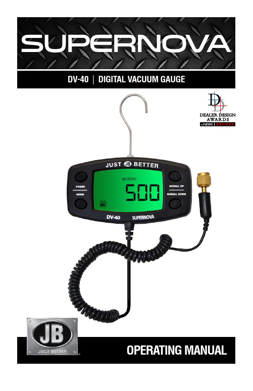
OPERATING MANUALDV-40 |DIGITAL VACUUM GAUGE SUPERNOV A®SPECIFICATIONSVacuum Reading Range 12,000 to 10 micronsPower Supply AC adapter (included) or three AA alkaline batteries Dimensions DV-41: 13" length x 11" width x 3.5" depth Shipping Weight 2.7 lbs (1.2 kg)Warranty 12 monthsFEATURESPower Button Mode Button5-ft Cord2JB INDUSTRIES •DV-40OperatingManual•630.851.9444•***************3JB INDUSTRIES•DV-40OperatingManual•630.851.9444•***************OPERATING INSTRUCTIONSPower SettingsTo power on, press the POWER button once.To power off, press and hold the POWER button for three seconds.Main Menu SettingsTo access the main menu user settings, press and hold MODE button for four seconds.Alarm SettingsTo enable the High Limit Alarm, hold the MODE button and press SCROLL UP .To enable the Low Limit Alarm, hold the MODE button and press SCROLL DOWN.To disable alarm, press POWER button once.When alarm is sounding, press any button to turn off alarm.Display Screen Start UpPress POWER button once to power gauge on. If unit display does not light up, check for correct battery installation. Startup display will show “JB”, “JUST BETTER”, a loading menu, followed by either the micron value or the over range indicator “oooooo.”The center bars in the loading menu move to indicate the unit is in initial warm up state. It may take up to 30 seconds for the unit to go into normal operation mode.The unit will display “oooooo” when it is at atmospheric pressure, or at a pressure over 12,000 microns. This indicates an over range condition. When the pressure is at or below 12,000 microns, the gauge will display the value.Note: The DV-40 is factory calibrated, field calibration is not required.Loading Menu – Warm up mode Atmospheric Pressure –Normal operation modeBattery Status IndicatorWhen the startup sequence is complete, the BATTERY STATUS INDICATOR will show current battery life status. While the unit is on, the status is updated once every second. Battery status indicator is not visible if the DV-40 is connected to external power source (AC adapter).Battery voltage status is as follows: Array3.5v or above 3.0 ~ 3.5v 2.7 ~ 3.0v 2.4 ~ 2.7v 2.1 ~ 2.4vWhen the battery voltage drops below 2.4 volts, the battery outline will flash and the unit will beep once per minute to alert the low battery condition. When battery voltage falls below 2.1 volts, the shutdown timer is activated. If voltage stays below 2.1 volts for thirty seconds, the DV-40 will beep once and power off. If power is restored during this time, shutdown is canceled.MENU SETTINGSAccessing Main Menu and Sub Menu Settings1. Press and hold MODE button for four seconds to access main menu settings.2. Press SCROLL UP and SCROLL DOWN buttons to cycle through all available main menu options:• “UNIT”• “AL--LO”• “AL--HI”• “BEEP”• “HI RES”• “AU-OFF”• “B-LITE”• “VER ID”3. T o select a menu option, press the MODE button to access sub menu. Press the SCROLL UP and SCROLL DOWN buttons to cycle through the sub menu options.4. T o select and store a sub menu option, press and hold the MODE button. Unit will display “STORED”, save your selection and return to menu. Each time the DV-40 powers on, previously stored user settings will be retrieved.5. Press POWER button once to return to the main menu.6. To exit main menu and return to normal operation mode, press the POWER button again.Note: When scrolling through menu settings, the POWER button acts as the cancel/exit button.4JB INDUSTRIES •DV-40OperatingManual•630.851.9444•***************Unit Selection (UNIT)When the alarm menu is active, a constant pressure value equivalent to 1000 microns is displayed using the currently selected units (EG: 133.31 for Pascals). The current selection is shown at the top of the main display screen.Available unit selections are: Microns, PSIA, inHg, Pascals, Torr, mTorr and mBar.Factory default setting is “MICRONS”.To scroll the selection, use the SCROLL UP and SCROLL DOWN buttons.To cancel, press the POWER button.To select and store the setting shown, press the MODE button. When a setting is stored, you will be returned to main menu selections. Press POWER to return to normal operation mode.Low Alarm Setting (AL--LO)The Low Alarm setting sets the pressure level where an alarm will be sounded. Setting a specific alarm level selection DOES NOT make the alarm active; it specifies the pressure level BELOW which the alarm will sound once the user enables the Low Limit Alarm (press MODE and SCROLL DOWN buttons to enable). Available settings are: 50, 100, 250, 500, 1000, 1250, 1500, or 2000 microns.Factory default setting is “500” microns.Default values are listed in microns, however values will be displayed in the current units selected. For example, if the user defined Unit Selection setting is Pascals, units displayed will be: 7, 14, 33, 66, 133, 166, 200, and 266 (The Pascal conversion of the 50 – 2000 micron values).The “ALARM”, “LOW” icon will be displayed to indicate you are setting up the Low Limit Alarm.To scroll the selection, use the SCROLL UP and SCROLL DOWN buttons.To cancel, press the POWER button.To select and store the setting shown, press the MODE button. When a setting is stored, you will be returned to main menu selections. Press POWER to return to normal operation mode.Low Limit AlarmMODE and SCROLL DOWN buttons enable the Low Limit Alarm.Low Limit Alarm can be enabled in all cases including when the pressure is in OVER RANGE except for when the sensor is not connected.An enabled Low Limit Alarm will display the “LOW”, “ALARM” icon on the main display screen, and will disable the High Alarm setting.If Low Limit Alarm is enabled and the pressure is less than or equal to the preset, user defined Low Alarm setting limit value, the alarm will alert with a beep sound every second and “ALARM”, “LOW” icon will flash. Beeping and flashing will continue even if the pressure rises above the Low Limit Alarm setting. Press any button to turn off the alarm.High Alarm Setting (AL--HI)The High Alarm setting sets the pressure level where an alarm will be sounded. Setting a specific alarm level selection DOES NOT make the alarm active; it specifies the pressure level ABOVE which the alarm will sound once the user enables the High Limit Alarm (press MODE and SCROLL UP buttons to enable).JB INDUSTRIES •DV-40OperatingManual•630.851.9444•***************5Available settings are: 50, 100, 250, 500, 1000, 1250, 1500, or 2000 microns.Factory default setting is “2000” microns.The default values are listed in microns, however values will be displayed in the current units selected. For example, if the user defined Unit Selection setting is Pascals, units displayed will be: 7, 14, 33, 66, 133, 166, 200, and 266 (The Pascal conversion of the 50 – 2000 micron values).The “ALARM”, “HIGH” icon will be displayed to indicate you are setting up the High Limit Alarm.To scroll the selection, use the SCROLL UP and SCROLL DOWN buttons.To cancel, press the POWER button.To select and store the setting shown, press the MODE button. When a setting is stored, you will be returned to main menu selections. Press POWER to return to normal operation mode.High Limit AlarmMODE and SCROLL UP buttons will enable the High Limit Alarm ONLY IF the existing pressure is below the preset, user defined High Alarm setting. If the existing pressure is higher than the preset, user defined High Alarm Limit, the High Limit Alarm cannot be enabled. If the Low Limit Alarm is currently enabled, setting the High Limit Alarm will disable the Low Limit Alarm even if the High Limit Alarm fails due to pressure readings above the High Limit Alarm setting. An enabled High Limit Alarm will display the “HIGH”, “ALARM” icon on the main display screen, and will disable the Low Alarm setting.If High Limit Alarm is enabled and the pressure is greater than or equal to the preset, user defined High Alarm setting limit value, the alarm will alert with a beep sound every second and the “ALARM”, “HIGH” icon will flash. Beeping and flashing will continue even if the pressure drops below the High Limit Alarm setting. Press any button to turn off the alarm.Button-press Feedback (BEEP)Key-press feedback determines whether an audible sound is heard each time a button is pressed. Available settings are: ON, OFF. Factory default setting is “ON”.To change the selection, use the SCROLL UP or SCROLL DOWN button. To cancel, press the POWER button. To select and store the setting shown, press the MODE button. When a setting is stored, you will be returned to main menu selections. Press POWER to return to normal operation mode.Display Resolution (HI RES)The display resolution menu allows you to select whether pressure will be shown at high resolution. High resolution means that pressure is shown as-is, in one unit increments.Available settings are: ON, OFF. Factory default setting is “OFF”.When the setting is OFF, the reading display is rounded.To change the selection, use the SCROLL UP or SCROLL DOWN button.To cancel, press the POWER button.To select and store the setting shown, press the MODE button. When a setting is stored, you will be returned to main menu selections. Press POWER to return to normal operation mode.Note: Even if high resolution display is ON, pressure values above 1000 microns will be rounded off according to the current display pressure.6JB INDUSTRIES •DV-40OperatingManual•630.851.9444•***************Auto Shutdown (AU-0FF)To conserve battery life, the DV-40 will power off after a period of inactivity (no button-press).Available settings are: OFF, 10, 15, 30, 45, 60, or 90 minutes. Factory default setting is “30” minutes. When Auto Shutdown is set to “OFF”, the DV-40 will not automatically power off.To change the selection, use the SCROLL UP or SCROLL DOWN button.To cancel, press the POWER button.To select and store the setting shown, press the MODE button. When a setting is stored, you will be returned to main menu selections. Press POWER to return to normal operation mode.Note: Even if auto shutdown has been deactivated, a low battery condition will power off the DV-40.Back Light Persistence (B-LITE)Back Light Persistence determines the number of seconds that the back light will stay on after the last button activity.Available settings are: OFF, 10, 15, 30, 45, 60, or 90 seconds. Factory default setting is “10”.To change the selection, use the SCROLL UP and SCROLL DOWN buttons.To cancel, press the POWER button.To select and store the setting shown, press the MODE button. When a setting is stored, you will be returned to main menu selections. Press POWER to return to normal operation mode.Note: While in the menu system, the back light will remain on unless it has been disabled by selecting “OFF”.Version Information (VER ID)The VER ID menu provides details regarding serial number and product/sensor firmware release versions. The main CPU Firmware release version (EG: “Fr 1.87”) displays initially. Pressing SCROLL DOWN will display the serial number (EG: “n12345”), and sensor CPU Firmware release version (EG: “Sr 6.45”). The POWER or MODE button will return to menu selection.MAINTENANCECleaning Vacuum Sensor1. Fill brass sensor fitting with a few drops of isopropyl alcohol.2. Cover the opening with a finger and gently shake to allow alcohol to rinse the sensor.3. Pour out alcohol and allow sensor to dry for 20 minutes before using gauge.JB INDUSTRIES •DV-40OperatingManual•630.851.9444•***************78DV-40OperatingManual•630.851.9444•***************PARTS LISTRETURN FOR REPAIREvery effort has been made to provide reliable, superior quality products. However, in the event your instrument requires repair, please contact JB Customer Service Department to obtain a Return Goods Authorization (RGA) number. Ensure that all returned products are packed to avoid any damage in shipment. Paperwork should be placed in a separate plastic bag and should include JB’s assigned RGA number, a description of the problem and any customer assigned repair or purchase order number, if applicable.Contact Customer Service for RGA number: 800.323.0811 Toll 800.552.5593 Toll FaxProducts should be shipped with freight prepaid to:J B Industries RGA#_________ 601 N. Farnsworth Ave. Aurora, IL 60505 630.851.9444 Tel 630.851.9448 FaxWARRANTYDV-40 Digital Vacuum Gauges are warrantied against defects in materials and workmanship for 12 months from date of purchase. JB products are guaranteed when used in accordance with our guidelines and recommendations. Warranty is limited to the repair, replacement, or credit at invoice price, (our option) of products which in our opinion are defective due to workmanship and/or materials. In no case will we allow charges for labor, expense or consequential damage. Repairs performed on items out of warranty will be invoiced on a nominal basis; contact wholesaler for details. Additional product information available online at .Part No. DV-41-308 0917 Printed in the USA ©2017 JB Industries, Inc.PART NO.DESCRIPTIONDV-41DV-40 digital vacuum gauge with AC adapter and carrying case DV-40CAC adapter and carrying case only DV-40AC AC adapter onlyDV-40HK Hanging hook replacementA34000D 1/4" QC x 1/4" access tee w/depressorP90009O-ring replacement (10 pack)。
维氏硬度计401 402MVA操作手册说明书

401MVATM /402MVA维氏硬度计操 作 手 册执行标准 GB/T4340(1.2)上海凤柏仪器仪表有限公司 Shanghai Fengbo Instruments Co.,Ltd目录1简介 (1)1.1机器概述 (1)1.2维氏硬度和努力硬度的原理 (1)2主要技术参数 (3)2.1机器主要参数 (3)3仪器的安装和调试 (4)3.1. 硬度计的工作条件 (4)3.2 拆箱和安装 (5)4 面板键功能介绍 (7)4.1机器的面板按键及其功能 (7)5硬度计的使用: (8)5.1硬度计的操作使用: (8)6 硬度计的维护及操作注意事项 (12)6.1.光源维护 (12)6.2 保险丝的更换 (13)6.3金刚石压头 (14)6.4 测微目镜 (14)6.5 试样 (15)6.6力、压痕大小的选择 (17)7 .装箱单 (18)1简介1.1机器概述首先感谢您选用本公司产品及浏览本说明书。
401/402MVA 显微维氏硬度计最适合于测试金属结构,包括微小的零件、薄板、金属箔、优质电线、薄硬化层和电镀层。
它还可用于测试诸如玻璃、珠宝和陶瓷等用洛氏测试方法及其它相对大试验力测试无法测试的非金属材料。
特别的是,它能遵循金属的结构,测试感应硬化或渗碳化等材料的内部硬度。
401/402MVA 显微硬度计是光机电一体化的高新技术产品,该硬度计造型新颖,具有良好的可靠性、可操作性和重复性,是测试显微硬度的理想产品。
该机采用C 语言编制程序,高倍率光学测量系统和光学双通道结构,光电、光偶传感等新技术。
通过按键操作,在按键上能输入测量压痕的长度、在LCD 屏幕上能显示硬度值、换算标尺、试验力、试验力保持时间和测量次数等。
401/40MVA2硬度计还可根据用户特殊需求配置,能对所测压痕和材料金相组织进行拍摄、视屏测量装置和压痕自动测量装置.以及努氏硬度的测定.1.2维氏硬度和努力硬度的原理1.2.1 维氏HV维氏硬度试验是用136°正菱形金刚石压头,以规定试验力(F)压入被测试物体的表面,经规定的保持试验力时间后,卸除试验力,用测微目镜测量试件表面的压痕对角线(d),计算压痕的锥形表面积所承受的平均压力(N/mm 2),即维氏硬度值。
耐压测试仪操作指导书 Microsoft Word 文档 (2)

1.目的:为了确保能正常使用并维护该仪器.2.适用范围:适用於LK2672C型号的耐压测试仪.3.操作方法:3.1:将电压调整旋钮逆时针调到头.3.2:关掉仪器电源开关.3.3:将机器AC电源插头插入220V AC电源.3.4:将电源开关按至“开”位置.3.5:设置“AC/DC”开关至所需要的电压种类,开关置於AC位置,则采用交流电压测试;置於DC位置,采用直流电压测试.3.6设置漏电流报警值,用户根据被测试产品的要求选择漏电电流档位及设置漏电流报警值,设置时,需将测试/预置开关按置开关按至预置位置.3.7:如果要设置时间控制,根据测试要求设定所需要的测试时间,且将定时开关按至开位置,无需时控,将定时开关按至“关”位置.3.8按启动开关,则高压指示灯亮,且有高压输出.3.9:顺时针调节调压旋钮,输出测试电压逐渐升高,直至调节到你所需要的电压值为止.3.10:被测试产品的一端连接於高压输出孔,另一端连接於被测接地端,如果选择的电压为AC,则应选用AC高压输出孔;如果选择的电压为DC,则应选择用DC高压输入孔,不可混乱.3.11:测试时,需将测试/预置开关按至“预置”位置,被测试产品中电流超过设定值,则测试电压被切断,同时产生报警声,报警指示灯亮,这种情况下,被测试产品被判为不合格.3.12:复位开关用作切断测试电压,按一下该开关,测试电压被切断,高压指示灯熄灭。
3.13:遥控测试:插上遥控插头,按下高压棒上的开关,高压棒上的指示灯亮,同时测试灯亮,将电压调到所需测试值,如果复位,松开高压棒上开关即可.编制:审核:4.注意事项:4.1:该测试仪器会产生高压,所以必须绝对注意安全.4.2:仪器必须可靠接地.4.3:为避免意外电击,操作者应带绝缘橡胶手套和站/坐在绝缘橡胶垫上.4.4:被测试产品应放置在适当的绝缘垫上.4.5:接通电源开关前,必须将调压旋钮以逆时针方向旋转至尽头.4.6:当不使用该仪器时,应将调压旋钮逆时针调至尽头,并关掉电源,以防止非专业操作。
Aptima 组合2检测试纸与其他生物标志物检测说明书

Collection Device
ThinPrep Pap Test Aptima Multitest Swab, Aptima Urine
Aptima Unisex Swab ThinPrep Pap Test Aptima Multitest Swab Aptima Multitest Swab Aptima Multitest Swab
Trichomonas vaginalis NAAT Chlamydia trachomatis / Neisseria gonorrhoeae / Trichomonas vaginalis NAAT Herpes Simplex Virus 1 & 2 NAAT
Test Code
LAB491 87491.11 LAB502323 LAB1093 LAB1092 LAB1091 LAB2097
Sample Type
Cervicovaginal Vaginal, Throat, Rectal, Urine Conjunctiva, Male Urethral, Endocervical
Cervicovaginal Vaginal Vaginal
Anogential lesion
8/31/2021
8/31/2021
Bellin Health Test Order Codes
Test Description
Image-Guided Pap Test Image-Guided Pap Test with reflex to Aptima HPV when ASCUS Image-Guided Pap Test with reflex to Aptima HPV when ASCUS or Negative Image-Guided Pap Test and Aptima HPV Aptima HPV Genotype 16, 18/45 Cytology Non-Gynecological
高压测试仪作业指导书
高压测试仪作业指导书引言:高压测试仪是一种用于检测和测量高压电器设备的工具。
它被广泛应用于电力行业、工业生产和实验室等领域,用于确保电器设备的正常运行和安全。
本作业指导书将为操作高压测试仪的人员提供详细的操作步骤和注意事项,以确保使用的安全性和准确性。
一、安全措施在操作高压测试仪之前,请务必严格遵守以下安全措施,以防止意外事故的发生:1. 佩戴防护眼镜和绝缘手套,以保护眼睛和手部免受高压电流的伤害。
2. 在操作高压测试仪时,确保周围环境干燥,避免雨天等湿润环境。
3. 避免将高压测试仪暴露在高温或极端寒冷的环境中。
4. 仔细阅读并理解高压测试仪的用户手册,并严格按照说明进行操作。
二、高压测试仪的组装在进行高压测试之前,需要正确组装高压测试仪。
按照以下步骤进行:1. 注意事项:a. 确保所有组装工作在无压状态下进行。
b. 仔细检查所有组件的完整性,如电缆、探头等。
c. 确保所有连接紧固,并没有松动或脱落。
2. 将探头插入高压测试仪,并确保插头牢固连接。
3. 将测试仪的电缆连接到电源,确保电源稳定并符合要求。
4. 检查电缆的完整性,如有破损或裸露的电线,请及时更换。
三、高压测试仪的操作在进行高压测试之前,请按照以下步骤操作高压测试仪:1. 将高压测试仪置于平稳的工作台上,并确保工作台干燥平整。
2. 打开高压测试仪的电源开关,等待设备的预热时间。
3. 设置测试仪的需要测试的电压范围,并确保设备的调节准确。
4. 将待测设备连接到测试仪上,确保连接牢固。
5. 缓慢通过调节旋钮增加电压,注意观察被测设备的反应。
6. 在测试完成后,缓慢减小电压并将电压调节旋钮调至最低档位。
7. 关闭高压测试仪的电源开关,待设备冷却后可以拔下电源线。
四、维护和保养为了确保高压测试仪的长期使用和准确性,应当注意维护和保养:1. 定期清洁高压测试仪的外表面,使用干净的布进行擦拭。
2. 检查电缆和探头的完整性,如有破损需立即更换。
3. 定期校准高压测试仪,确保测量的准确性。
高压电阻测试仪操作规程

高压电阻测试仪操作规程编制:审批:广州xx工程建设监理有限公司深圳xxxx工程监理中心高压电阻测试仪操作规程一、高压绝缘电阻测试仪该仪器适用于测量各种变压器、电机、电缆、开关、电器设备的绝缘电阻。
面板说明:1.显示液晶屏2.选择按钮3.应急关机按钮4.背光与数据清楚按钮5.▼选择按钮6.电源开关按钮7.比较功能按钮 8.绝缘电阻测量按钮 9.直流电压测量按钮10.定时器按钮 11.交流电压测量按钮 12.测试使用按钮B传输按钮 14.数据存储按钮 15.读存储数据按钮16.选择按钮 17.选择按钮 18.LINE:高压输出插入19.高压线屏蔽插入口 20.GUARD:接地保护插入21.EARTH:高阻测量插入口 22.专用测试夹和专用双插头测试二、测试仪操作方法1、绝缘电阻测量接线示意图:2、测量步骤:(1) 3.2.1开启电源开关“ON/OFF”,选择所需电压等级,开机默认为500V 档,选择所需电压档位,对应指示灯亮,轻按一下高压“启停”键,高压指示灯亮,LCD显示的稳定数值乘以10即为被测的绝缘电阻值。
当试品的绝缘电阻值超过仪表量程的上限值时,显示屏首位显示“1”,后三位熄灭。
关闭高压时只需再按一下高压“启停”键,关闭整机电源时按一下电源“ON/OFF”。
注:测量时,由于试品有吸收、极化过程,绝缘值读数逐渐向大数值漂移或有一些上下跳动,系正常现象。
(2) 3.2.2连续测量:按TIME 键选择连续测量模式,在液晶屏上无定时器标志显示,此后按住TEST键1秒能够进行连续测量,输出绝缘电阻测试电压,测试红灯发亮,在液晶屏上高压提示符0.5s闪烁。
在测试完以后,压下TEST键,关闭绝缘电阻测试电压,测试红灯灭且无高压提示符,在液晶屏上保持当前测量的绝缘电阻值。
3、接线端子符号含义:(1)测量绝缘电阻时,线路“L”与被测物同大地绝缘的导电部分相接,接地“E”与被测物体外壳或接地部分相接,屏蔽“G”与被测物体保护遮蔽部分相接或其他不参与测量的部分相接,以消除表泄漏所引起的误差。
国家体外诊断试剂标准物质使用说明书 HPV 全基因组分型参考品
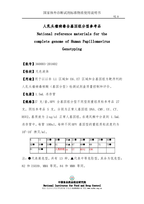
中国食品药品检定研究院人乳头瘤病毒全基因组分型参考品National reference materials for thecomplete genome of Human PapillomavirusGenotyping【批号】360003-201602【性状】无色液体【用途】用于以以非L1区域如E6、E7区域和全基因组为靶序列的人乳头瘤病毒核酸(基因分型)检测试剂盒质量控制和评价。
【包装】1.5mL 冻存管【规格】27支/套,HPV 全基因组分型不同型别重组质粒参考品27支,阴性参考品5支,分别为正常人基因组DNA、CMV、UU、CT、HSV2。
基质液为2ng/ul 正常人基因组,在通风橱中分装到1.5mL 冻存管中,每管100ul,每种不同HPV 基因型的重组质粒浓度约为106-107拷贝/ml。
注:●代表高危型,共有13种。
▲代表中等危险型,其余为低危型;82和ISO39、MM4等同,84和MM8等同。
中国食品药品检定研究院【使用方法和要求】1.本品核酸提取前常温溶解、混匀。
2.使用时要求按照106-107拷贝/ml 浓度进行稀释,稀释液应为2ng/ul 正常人基因组TE 溶液。
本参考品使用时,应满足:1、准确性(阳性符合率):要求检测试剂盒检测范围内人乳头瘤病毒不同型别国家分型参考品结果应均为阳性。
2、特异性:a)采用实时荧光PCR、PCR-杂交等原理检测试剂盒检测5份阴性参考品,检测结果应为阴性。
检测本参考品22种不同型别阳性参考品,检测结果应为不在其检测范围内的高危型别,应不得出现交叉;不在其检测范围内的低危型别,交叉反应率应分别不大于10.0%。
b)采用杂交捕获-化学发光法原理的检测试剂盒检测5份阴性参考品,检测结果应为阴性。
检测本参考品22种不同型别阳性参考品,检测结果应符合制造商的要求并注明可能产生交叉反应的型别。
3、重复性(精密度):a)采用实时荧光PCR 原理的检测试剂盒,要求批内精密度应符合Ct 值的变异系数(CV,%)不大于5.0%。
Additel 920高压测试泵用户手册说明书

High Pressure Test PumpAdditel 920OVERVIEWThe 920 High Pressure Test Pump is a hand operated pressure pump designed to generate pressure from 95% vacuum to 3,000psi (200bar). With a long lever, it just takes 40 seconds to reach 3,000 psi (200 bar). A high-quality screw press is designed for fine pressure adjustment, with an adjustment resolution up to 10 Pa (0.1 mbar). A specially designed shut-off valve makes the pressure as stable as possible during calibration. A built-in gas-liquid isolator protects the pump from moisture and dirt to reduce the need for maintenance. The residual liquid in the pump introduced from devices under test will be pushed out and collected during pressure release. Two hand-tight quick connectors installed on the pump allow easy connecting and disconnecting to the test pump without the need for PTFE tape or wrenches. The 920 is an ideal comparison test pump for pressure instruments calibration.High EfficiencyGenerate 3,000 psi (200 bar) in 40 seconds.Adjustment Resolution0.001 psi (10 Pa, 0.1 mbar).High-quality screw press for fine pressure adjustment.Great StabilityA specially designed shut-off valve makes the pressure as stable as possible during calibration.Durable and Minimal MaintenanceBuilt-in gas-liquid isolator protects the pump from moisture and dirt.The residual liquid in the pump introduced fromdevices under test will be collected and then pushed out and collected during pressure release.Anticorrosive and wear resistant material are used to improve the reliability further. Hand-tight Quick ConnectorsAllows easy connecting and disconnecting to the test pump without the need for PTFE tape or wrenches.Media: Air.Generated Pressure Range95% vacuum to 3,000 psi (200 bar) positive pressure Adjustment Resolution: 10 Pa (0.1 mbar/0.0015 psi)Material: Ram/adapters: SST Body: SST/aluminum Seals: Buna-N, F357ConnectionHand-tight connectors for both test gauge and reference gauge.Test Gauge Connection: 1/4NPT female, 1/2NPT female, 1/4BSP female, or M20X1.5 female Reference Gauge Connection: 1/4NPT female,1/2NPT female , 1/4BSP female, or M20X1.5 female Dimensions:Height: 7.00'' (178 mm);Base: 21.26' (540 mm) x 10.63'' (270 mm).Weight: 14.3 lb (6.5kg). Warranty:: 1 yearFEATURESSPECIFICATIONSOptional AccessoriesORDERING INFORMATIONAccessories includedO-ring: 20 pcs Manual: 1 pcModel NumberGenerate 95% vacuum to 3,000 psi (200 bar) pressure Generate 3,000 psi (200 bar) in 40 seconds Minimal maintenanceHand-tight quick connectors First one in the world。
Egnater Tweaker-40 产品说明书

TWEAKER-40 Owner’s Manual TWEAKER-40 HEADTWEAKER-40 HEADINSIDE THIS OWNER’S MANUALGreetings from Bruce Egnater .........................................2Your Officially A Tweaker ................................................3 Important Information .....................................................4Safety Precautions .............................................................5The Front Panel Explained ..............................................6-7Finding the Sound You Want ...........................................8-9The Rear Panel Explained ................................................10-11Connecting your speakers ................................................12Tweaker footswitch ...........................................................13Tweaker-40 Specifications / Tube Chart .........................14Personalize Your Settings .................................................15Contact & Warranty .. (16)Greetings………..I would like to personally thank you for choosing Egnater as your “Tone Partner”. Our goal is to provide you with the best tools we can to help you express yourself to the fullest. Your amplifier is an integral piece in your never ending “Tone Quest”. Our commitment to helping you achieve that goal is our passion. Our hope is that you will take advantage of the years of innovative tube amp designs we offer and use it to find the sound that is “in your head”.Thank you for putting your trust in Egnater.Best Regards,Bruce Egnater23Each channel has a full complement of Tweaker switches for seemingly endless varia-tions. The master tone control section has our magical BRIT/VX/USA voicing switch that gives you instant access to all the great classic and modern tones. The VINTAGE/MODERN voicing switches further enhance the tone possibilities. The Tweaker amps exist to satisfy your “Jones for Tones”. In no time at all, you will be hooked.YOU’RE OFFICIALLY A TWEAKER!!Congratulations. You have just entered the world of “Tone Tweakers”.The Tweaker-40 is your next step into the never ending quest for “The Tone”. The Tweaker-40 gives you double the tone, power and features of our original Tweaker. The 40 sports two identical channels for easy, seamless switching between two pre-set Tweaker tones.Powered by a pair of 6L6 power tubes for a solid 40 watts of room filling power, the 40 could be your ultimate gigging amp.IMPORTANT INFORMATIONARD, OPERATE NEAR ANY WATER SOURCE1. Read these instructions – All the safety and operating instructions should be read before this product is operated.2. Keep these instructions – The safety and operating in-objects filled with liquids, such as vases, shall not be placed on apparatus.17. WARNING: For the terminals marked with symbol of “ ” may be of sufficient magnitude to constitute a risk of electric shock. The external wiring connected to the 19. This lightning flash with arrowhead symbol within an equilateral triangle is intended WARNINGshould be used only with a cart or stand that50/60Hz 300 WATTS QUICK START GUIDE7to take some of the “honk” out of your humbucking pickups. Try it on your high gain settings to get some serious “metal-ish” chunk.18) CHANNEL 1 GAIN: This controls the amount a “drive” in the preamp. Low settings of the GAIN knob (with higher settings of the vOLume knob) will keep the sound big, full and beautiful. You can also use higher settings of the GAIN knob to push the channel into overdrive and get some really raucous rock & roll crunch tones.19) CHANNEL 1 ON LED: Tells you CHANNEL 1 is active.20) CHANNEL 2 TIGHT/DEEPSWITCH: This switch is really useful for tightening up the low end, e speciallywhen pushing the gain. It works by cutting the deep bass at the beginning of the preamp. Setting the TIGHT switch up will result in a clearer, tighter tone. Down retains a full, big low end that is great for a really robust, fat rhythm sound.21) CHANNEL 2 HOT/CLEANSWITCH: In the CLEAN setting, the gain is reduced to make is easy t o dial in a pristine clean to moderate crunch with the GAIN knob. HOT unleashes the fury for high gain rock or singing solos.22) CHANNEL 2 BRIGHT/NORMAL SWITCH: As expected, the BRIGHT setting boosts. the high end. Do experi-ment with different combinations of the BRIGHT on and TREBLE knob down compared to the BRIGHT off and the TRebLe up. You will find that with the BRIGHT on and the TREBLE down, the tone will be a little less midrangy compared to the BRIGHT off and the TREBLE turned up.23) NORMAL/MID CUT SWITCH: In the NORMAL setting, the midrange is, well, normal. The MID CUT on opens a whole new range of tones to further expand your “tonal palette”. Try using the MID CUT with your clean sound to create a pristine, almost acoustic tone or take some of the “honk” out of your humbucking pickups. Try it on your high gain settings to get some serious “metal-ish” chunk.24) CHANNEL 2 GAIN: This controls the amount a “drive” in the preamp. Low set-tings of the GAIN knob (with higher settings of the vOLume knob) will keep the sound big, full and beautiful. You can also use higher settings of the GAIN knob to push the channel into overdrive to get some really raucous rock & roll crunch tones.25) CHANNEL 2 ON LED: Tells you CHANNEL 2 is active.26) CHANNEL SELECT: This pushbut-ton selects CHANNEL 1 or CHANNEL 2. NOTE: This button is disabled when the footswitch in plugged in.27) GUITAR INPUT: Plug your guitar in here using a high-quality, shielded instru-ment cable.28) TWEAKER-40 LOGO: To remind you of why you are here. You are a “Tone Tweaker” and, as such, have certain obli-gations. First you must relentlessly carry on the “Tone Quest”. Next, you must neverbe fearful of turning knobs . You will never discover the potential if you don’t. There are no “correct” settings. What sounds great to you ARE the correct settings. (We do try to guide you a bit in the “Finding Your Sound” section). Take advantage of all the “Tone” possibilities sitting before you right now. Use the Tweaker to cre-ate those sounds, “in your head” that are yearning to be released to the world.SPECIAL NOTE:You may have noticed by now that we have given the same descriptions for all the controls on both channels. That is because both channels are identical. This gives you a seamless transition when switching channels. The array of switches allows you to set the channels to sound very different or very much alike. Maybe you want CHANNEL 1 to be really clean and CHANNEL 2 to have basically the same tone, only louder for solos? Or, you could set CHANNEL 1 for a sort of “rock ‘n roll” rhythm and CHANNEL 2 for a high gain solo sound. You won’t feel like you are playing through two different amps.FINDING THE SOUND YOU WANT! con’t9BLUES DELUXE BLUES SOLOSMOOTH SMOOTH JAZZY CLEAN JAZZY SOLOBRITISH BRITISH RHYTHM LEADTONE TIPS FOR TWEAKERS.......1) both channels on the TWeAKeR-40 are identical. Same gain, same tone, same everything for a seamless transition between sounds.2) The suggested settings above are just that ....... SuGGeSTIONS. use these as a starting point to TWeAK from. Turn the knobs. Flip the switches. Get a feel for what each one does. Think of each control as another color. You will be rewarded with a vast pallet of tones to choose from.3) When cranking the GAIN, the TIGHT switch is really useful for making the bass tighter and more solid.4) The less gain you use, the clearer and more defined your tone will be. Try to find a happy medium be -tween lots of gain (more fun to play) and less gain (cuts through the band better).5) When experimenting with the tone controls, be aware that turning the TRebLe up and the bRIGHTswitch off sounds very different from turning the TREBLE down and the BRIGHT switch on. Try both ways when tweaking the high end. You will find lower settings on the TRebLe knob result in a bit less mid range.6) The bRIGHT switches are tied to the GAIN controls. The higher the gain setting, the less effect the BRIGHT switch will have. You can use this to vary the amount of Brightness. Set the GAIN very low for maximum BRIGHT switch effect. If you want less, just turn the GAIN control up and reduce the MASTER volume accordingly.do find your effect is distorting, change the LeveL switch to INST (out). This should fix the problem. Of course, you still may occasionally encounter a device that simply won’t work properly in a loop. This is one of the reasons we discourage players from using pedals in a loop. You just spent a considerable amount of your hard earnedCONNECTING YOUR SPEAKERSTWO-BUTTON FOOTSWITCH13FEATURES AND SPECIFICATIONS。
HPV 检测试剂盒及检测方法[发明专利]
![HPV 检测试剂盒及检测方法[发明专利]](https://img.taocdn.com/s3/m/eb6a0bcaaff8941ea76e58fafab069dc502247ce.png)
(10)申请公布号(43)申请公布日 (21)申请号 201510897921.7(22)申请日 2015.12.08C12Q 1/70(2006.01)C12Q 1/68(2006.01)(71)申请人江苏博铼生技医疗科技有限公司地址213164 江苏省常州市武进区西太湖医疗科技产业园长扬路9号C2栋(72)发明人曹汀 李佩珊 王锦弘(74)专利代理机构广州华进联合专利商标代理有限公司 44224代理人万志香 黎艳(54)发明名称HPV 检测试剂盒及检测方法(57)摘要本发明涉及一种HPV 检测试剂盒及检测方法。
该HPV 检测试剂盒包括微载体、检测探针及扩增引物。
该HPV 检测试剂盒及检测方法可一次性对样本进行检测,可以减少所需的样本量,并有效提高检测效率。
该检测试剂盒及检测方法可结合多元检测以多重筛检技术及结合多元化生医检测系统,从而可以增加临床精准度与简便性。
并可结合影像辨识系统及相应的软体分析,可取得大量且完整的检测结果,检测效率进一步提高。
(51)Int.Cl.(19)中华人民共和国国家知识产权局(12)发明专利申请权利要求书2页 说明书11页序列表17页 附图2页CN 106854681 A 2017.06.16C N 106854681A1.一种HPV检测试剂盒,其特征在于,包括微载体、检测探针及扩增引物;所述微载体至少有一种,所述微载体具有编码信息,且针对不同HPV亚型的所述微载体的编码信息不同;所述检测探针选自:针对HPV 6亚型的序列为SEQ ID No.1的寡核苷酸探针、针对HPV 11亚型的序列为SEQ ID No.2的寡核苷酸探针、针对HPV 16亚型的序列为SEQ ID No.3的寡核苷酸探针、针对HPV 18亚型的序列为SEQ ID No.4的寡核苷酸探针、针对HPV 26亚型的序列为SEQ ID No.5的寡核苷酸探针、针对HPV 31亚型的序列为SEQ ID No.6的寡核苷酸探针、针对HPV 33亚型的序列为SEQ ID No.7的寡核苷酸探针、针对HPV 35亚型的序列为SEQ ID No.8的寡核苷酸探针、针对HPV 39亚型的序列为SEQ ID No.9的寡核苷酸探针、针对HPV 40亚型的序列为SEQ ID No.10的寡核苷酸探针、针对HPV 42亚型的序列为SEQ ID No.11的寡核苷酸探针、针对HPV 43亚型的序列为SEQ ID No.12的寡核苷酸探针、针对HPV 44亚型的序列为SEQ ID No.13的寡核苷酸探针、针对HPV 45亚型的序列为SEQ ID No.14的寡核苷酸探针、针对HPV 51亚型的序列为SEQ ID No.15的寡核苷酸探针、针对HPV 52亚型的序列为SEQ ID No.16的寡核苷酸探针、针对HPV 53亚型的序列为SEQ ID No.17的寡核苷酸探针、针对HPV 54亚型的序列为SEQ ID No.18的寡核苷酸探针、针对HPV 55亚型的序列为SEQ ID No.19的寡核苷酸探针、针对HPV 56亚型的序列为SEQ ID No.20的寡核苷酸探针、针对HPV 58亚型的序列为SEQ ID No.21的寡核苷酸探针、针对HPV 59亚型的序列为SEQ ID No.22的寡核苷酸探针、针对HPV 61亚型的序列为SEQ ID No.23的寡核苷酸探针、针对HPV 66亚型的序列为SEQ ID No.24的寡核苷酸探针、针对HPV 68亚型的序列为SEQ ID No.25的寡核苷酸探针、针对HPV 70亚型的序列为SEQ ID No.26的寡核苷酸探针、针对HPV 73亚型的序列为SEQ ID No.27的寡核苷酸探针、针对HPV 81亚型的序列为SEQ ID No.28的寡核苷酸探针、针对HPV 82亚型的序列为SEQ ID No.29的寡核苷酸探针以及针对HPV 83亚型的序列为SEQ ID No.30的寡核苷酸探针中的至少一种;且所述检测探针包覆对应的HPV亚型的微载体;所述扩增引物与所述检测探针对应,所述扩增引物包括选自:针对HPV 6亚型、HPV 11亚型、HPV 16亚型、HPV 18亚型、HPV 26亚型、HPV 31亚型、HPV 33亚型、HPV 35亚型、HPV 39亚型、HPV 40亚型、HPV 42亚型、HPV 43亚型、HPV 44亚型、HPV 45亚型、HPV 51亚型、HPV 52亚型、HPV 53亚型、HPV 54亚型、HPV 55亚型、HPV 56亚型、HPV 58亚型、HPV 59亚型、HPV 61亚型、HPV 66亚型、HPV 68亚型、HPV 70亚型、HPV 73亚型、HPV 81亚型、HPV 82亚型以及HPV 83亚型中的至少一种HPV亚型的保守区序列设计的上游引物和下游引物,且所述下游引物的5’端连接有标记物。
TESTEC 高电压探头 TT-HVP 40 用户指南说明书
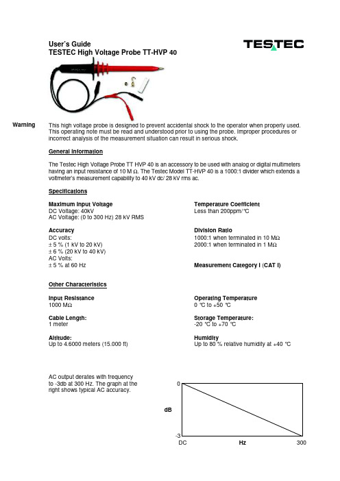
User’s Guide TESTEC High Voltage Probe TT-HVP 40This high voltage probe is designed to prevent accidental shock to the operator when properly used. This operating note must be read and understood prior to using the probe. Improper procedures or incorrect analysis of the measurement situation can result in serious shock.General InformationThe Testec High Voltage Probe TT HVP 40 is an accessory to be used with analog or digital multimeters having an input resistance of 10 M Ω. The Testec Model TT-HVP 40 is a 1000:1 divider which extends a voltmeter’s measurement capability to 40 kV dc/ 28 kV rms ac.SpecificationsMaximum Input Voltage Temperature CoefficientDC Voltage: 40kV Less than 200ppm/°CAC Voltage: (0 to 300 Hz) 28 kV RMSAccuracy Division RatioDC volts: 1000:1 when terminated in 10 M Ω ± 5 % (1 kV to 20 kV) 2000:1 when terminated in 1 M Ω ± 6 % (20 kV to 40 kV) AC Volts:± 5 % at 60 Hz Measurement Category I (CAT I)Other CharacteristicsInput Resistance Operating Temperature1000 M Ω 0 °C to +50 °CCable Length: Storage Temperature:1 meter -20 °C to +70 °CAltitude: HumidityUp to 4.6000 meters (15.000 ft) Up to 80 % relative humidity at +40 °CAC output derates with frequencyright shows typical AC accuracy.dBDC Hz 300WarningSafety Precautions • This high voltage probe must only be used by personnel who are trained, experienced, or otherwise qualified to recognize hazardous situations and who are trained in the safety precautions that are necessary to avoid possible injury when using such a device. • Do not work alone when working with high voltage circuits • For your own safety, inspect the probes for cracks and frayed or broken leads before each use. If defects are noted, DO NOT use the probe. • Hands, shoes, floor and work bench must be dry. Avoid making measurements under humid, damp or other environmental conditions that might effect the safety of the measurement situation. • It is advisable to turn the high voltage source off before connecting or disconnecting the probe. • The probe body should be kept clean and free of any conductive contamination. Refer to the section on cleaning. Operation • Connect the plugs to the volts [Hi] and com [Lo] terminals of your voltmeter • Select the desired voltage function and range; do not use autoranging • Whenever possible, turn the high voltage source off before making any connections • Connect the divider probe common lead (alligator clip) to a good earth ground or reliable chassis ground • Do not attempt to take measurements from sources where the chassis or return lead is not grounded• The ground lead is critical to the safe operation of the probe. Failure to make this connection when making high voltage measurements may result in personal injury or damage to the probe or volt-meter. This connection must always be made BEFORE the probe tip comes in contact with the high voltage and must not be removed until the probe tip has been removed from the high voltage source.• Do not connect the ground clip lead to the high voltage source for any reason.• Before turning the high voltage on, make sure that no part of your body is in contact with the device under test.• Measure the voltage remembering that the voltage being measured is 1000 times greater than the voltmeter reading.• Turn the high voltage off.• Disconnect the probe tip from the high voltage source BEFORE removing the ground clip lead.Cleaning• Clean only the exterior probe body and cables. Use a soft cotton cloth lightly moistened with a mild solution of detergent and water. Do not allow any portion of the probe to be submerged at anytime.• Dry the probe thoroughly before attempting to make voltage measurements.• Do not subject the probe to solvents or solvent fumes as these can cause deterioration of the probe body and cables.Testec Elektronik GmbH Phone +49 (0)69-943335-0 Westerbachstr. 58 Fax: +49 (0)69-943335-55D - 60489 Frankfurt www.testec.de Warning。
HVP 40 高压测试棒说明书
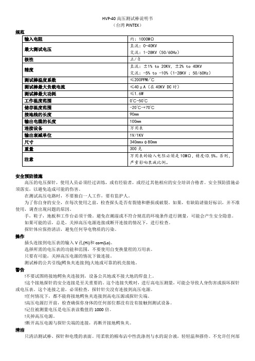
HVP-40高压测试棒说明书(台湾PINTEK)规范输入电阻约:1000MΩ最大测试电压直流:0-40KV交流:1-28KV(50/60Hz)极性正/负精度直流:±1% to 20KV,±2% to 40KV交流:-5% to -10%(1-28KV ; 50/60Hz)测试棒温度系数≤200PPM/℃测试棒最大负载电流≤40μA(在40KV DC时)测试棒最大功耗≤1.6W工作温度范围0℃-50℃储存温度范围-20℃-+70℃接地线的长度90mm输出电缆的长度100mm连接设备万用表输出衰减单位1V/1KV尺寸340mmxφ80mm重量300克注意万用表的输入电阻必须是10MΩ,精度<0.5%。
否则,严重影响衰减比例。
安全预防措施高压的电压探针,使用人员必须经过训练,或有经验者,或经过其他相应的安全培训合格者。
安全预防措施必须落实,以避免造成可能的伤害。
在测试高压电路时,不要独自一人工作,要有监护人。
为了你自身的安全,在每次使用之前,检查探头是否有裂缝和磨损或破裂。
如果,有缺陷请做好标识,并不准使用,调查出现问题的原因。
手,鞋子,地板和工作台必须干燥。
避免在潮湿或不符合规范的环境条件进行测量,可能会产生安全隐患。
如果可能的话,总是,关掉高压电源连接或断开连接的情况下,进行检查。
探针体应保持清洁,避免任何导电物质的污染。
操作插头连接到电压表的输入V孔(Hi)和com(Lo)。
选择所需的电压表的功能和范围,不要使用自变换量程的万用表。
只要有可能,关掉高压电源的情况下做连接。
测试棒的公共引线(鳄鱼夹连接到)大地或可靠的机壳接地。
警告!不要试图将接地鳄鱼夹连接到,设备公共地或不接大地的焊盘上。
!这个接地探针的安全连接是至关重要的。
这个连接失败时,进行高电压测量,可能会导致人身伤害或损坏探针或电压表。
这个连接之前,必须检查,探针针尖没有连接到高压电源。
!任何情况下,都不能将接地鳄鱼夹连接到高电压源或探针尖端。
最详细的M40 四合一检测仪的操作使用说明及注意事项

数据记录
z 所有仪器上的标准功能 z 始终打开 – 50 小时数据(4 个传感器 +
温度)
z 1 分钟记录间隔 z 50 小时后自动覆盖 z 通过 Datalink 配件下载至 PC
电池
z 内置锂离子电池盒(不可取出) z 不带泵时 18 小时运行时间,带泵时 12 小时运
行时间 z 随 M40 提供的经济充电器
传感器开口 显示屏 声音警报 向下箭头
On/Off
INDUSTRIAL SCIENTIFIC
CO H2S O2 LEL
M40
SP40 接触点
视觉警报 向上箭头 Enter
M40 功能(后)
可分离 皮带扣
充电器/ Datalink 端口
仪器操作
打开 M40
INDUSTRIAL SCIENTIFIC
CO H2S O2 LEL
M40
按下并按住 ON/OFF 键直到仪器发 短提示音并进入显示屏测试。
仪器操作
打开 M40
INDUSTRIAL SCIENTIFIC
CO H2S O2 LEL
M40
显示仪器徽标和软件版本
仪器操作
打开 M40
INDUSTRIAL SCFra bibliotekENTIFIC
CO H2S O2 LEL
按向上箭头访问“STEL 读数”
仪器操作
更改查看屏幕
STEL 读数
INDUSTRIAL SCIENTIFIC
CO H2S O2 LEL
M40
此屏幕将显示两个有毒气体传感器的
短期暴露极限 读数。
按向上箭头返回“实时读数”屏幕。
仪器操作
更改查看屏幕
实时读数屏幕
m40pro英思科仪器说明书

气体检测专家使用说明书多气体检测仪自1985年创建以来,英思科一直致力于通过帮助人们在工作一天后安全地回家,从而为世界作出贡献。
我们意识到,在任何既定时间内,千百万人将他们的生命寄托于我公司所践行的事业。
了解您的气体检测设备与解决方案供应商的推动力是什么,这一点很重要。
英思科的推动力来自三方面。
首先是我们的使命。
保护地球各个角落人类的生命。
随时随地提供最高品质的产品和最优质的服务。
我们如何保护人类生命?调整我们对于结果的期望。
其必须具备最高质量,并超出客户预期。
为保证这一点,我们在资本设备和商业系统领域开展积极投资。
我们与现有的最佳供应商合作。
我们不会让任何对生命安全有威胁的产品出厂。
第二个方面是员工第一的经营理念。
我们相信,良好的业绩来自于以员工第一、客户第二和股东第三的行为准则。
我们只有拥有世界上最优秀的员工并配备最优质的工具,才能为客户提供最优质的服务。
只有为客户提供良好的服务,公司才能兴旺发达。
但这一切都源于设计、研制并销售可靠的解决方案。
在为您提供最优秀人员这一方面,我们绝不妥协。
我们最后的驱动力来自我们的独立自主性。
从1993至1999年,英思科曾是一家上市公司。
作为上市公司,我们认为我们的使命和经营理念与华尔街和外部股东的需求不一致。
作为私有企业,我们能够对我们的人员和系统进行再投资,根据更完善的长期工作重点做出决策。
我们积极工作,保持英思科的强大实力与独立性。
如果您已是我们的客户,感谢您的业务和合作。
如果不是,我希望能有机会向您展示英思科优秀人员有能力为您创建一个更加安全的工作场所。
如果我能为您提供任何帮助,请直接致电(+1-412-490-1842)或发email(jmcelhattan@)与我联系。
谢谢。
Justin McElhattan英思科总裁兼CEO英思科宗旨保护地球各个角落人类的生命随时随地提供最高品质的产品和最优质的服务版权声明警告及注意事项常规人员危险情况、毒物和污染物影响监测仪性能的因素认证建议做法M40 Pro资源M40 Pro 功能仪器拆箱箱内部件反馈问题监测仪概述特点与功能显示屏幕警报监测仪设置电池特性和监测仪兼容性充电锂离子电池盒开机和关机配置介绍说明操作过程(逐个屏幕演示)监测仪使用和维护调零、标定和通气测试介绍说明随机提供准备气瓶操作过程(逐个屏幕演示)现场空气采样建议做法清洁1 1 1 1 1 2 2 2 3 3 4 4 4 5 5 7 7 11 11 11 12 14 14 14 15 23 23 23 24 24 25 25 32 32目录维护电池盒监测仪转换传感器、传感器防水膜、LCD 和振动电机更换泵模块分解图和要点产品、规格与认证M40 Pro 配件与部件监测仪规格传感器规格认证质保责任限定英思科便携式检测仪系列32 33 34 35 38 39 43 43 45 45 46 47 48 49版权声明M40 Pro是英思科公司的商标。
高压数字绝缘电阻测试仪说明书

高压数字绝缘电阻测试仪说明书由于输入输出端子、测试柱等均有可能带电压,在插拔测试线、电源插座时,会产生电火花,小心电击,避免触电危险,注意人身安全!安全要求请阅读下列安全注意事项,以免人身伤害,为了避免可能发生的危险,只可在规定的范围内使用。
只有合格的技术人员才可执行维修。
—防止火灾或人身伤害使用适当的电源线。
只可使用本产品专用、并且符合本产品规格的电源线。
正确地连接和断开。
当测试导线与带电端子连接时,请勿随意连接或断开测试导线。
注意所有终端的额定值。
为了防止火灾或电击危险,请注意所有额定值和标记。
在进行连接之前,请阅读使用说明书,以便进一步了解有关额定值的信息。
使用适当的保险丝。
只可使用符合规定类型和额定值的保险丝。
避免接触裸露电路和带电金属。
有电时,请勿触摸裸露的接点和部位。
请勿在潮湿环境下操作。
请勿在易爆环境中操作。
-安全术语警告:警告字句指出可能造成人身伤亡的状况或做法。
目录一、介绍 (5)二、功能特点 (5)三、技术指标 (6)四、使用说明 (7)五、注意事项 (8)一.介绍1.仪表工作原理HT2671数字兆欧表由中大规模集成电路组成。
本表输出功率大,短路电流值高,输出电压等级多(有四个电压等级)。
工作原理为由机内电池作为电源经DC/DC变换产生的直流高压由E 极出经被测试品到达L极,从而产生一个从E到L极的电流,经过I/V变换经除法器完成运算直接将被测的绝缘电阻值由LCD显示出来。
2.仪表电路框图如图所示:3.仪表使用范围本仪表是电力、邮电、通信、机电安装和维修以及利用电力作为工业动力或能源的工业企业部门常用而必不可少的仪表。
它适用于测量各种绝缘材料的电阻值及变压器、电机、电缆及电器设备等的绝缘电阻。
二.功能特点本表具有以下特点:·输出功率大、带载能力强,抗干扰能力强。
本表外壳由高强度铝合金组成,机内设有等电位保护环和四阶有源低通滤波器,对外界工频及强电磁场可起到有效的屏蔽作用。
HPV基因分型测定标准操作规程
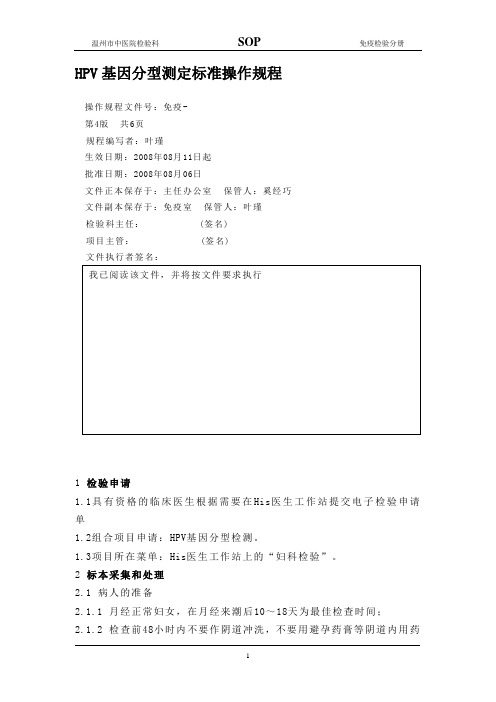
HPV基因分型测定标准操作规程操作规程文件号:免疫-第4版共6页规程编写者:叶瑾生效日期:2008年08月11日起批准日期:2008年08月06日文件正本保存于:主任办公室保管人:奚经巧文件副本保存于:免疫室保管人:叶瑾检验科主任:(签名)项目主管:(签名)文件执行者签名:1 检验申请1.1具有资格的临床医生根据需要在His医生工作站提交电子检验申请单1.2组合项目申请:HPV基因分型检测。
1.3项目所在菜单:His医生工作站上的“妇科检验”。
2 标本采集和处理2.1 病人的准备2.1.1 月经正常妇女,在月经来潮后10~18天为最佳检查时间;2.1.2 检查前48小时内不要作阴道冲洗,不要用避孕药膏等阴道内用药物;2.1.3 检查前48小时最好不要行性生活;2.1.4 检查前不进行醋酸或碘液涂抹;2.2 标本采集2.2.1 按医生指示,仰卧于检查床上;2.2.2由医生以窥阴器或阴道张开器暴露宫颈。
然后使用专用的HPV采样刷置于宫颈口采集标本;(最好在取样前先用棉签擦去宫颈分泌物)2.2.3将专用宫颈刷置于宫颈口,轻轻搓动宫颈刷使其顺时针旋转5圈;2.2.4慢慢取出宫颈刷,将其放入标有病人编号的取样管中,取样管内已加有专用细胞保存液,折断其刷头入管中,拧紧瓶盖。
2.2.5 标本采集后,在电脑终端检验标本采集确认,电脑自动产生标本采集时间。
2.2.6 标本采集及确认后,临床标本要及时运送至检验科。
检验科接收人员Lis接收电脑终端刷取标本条形码接收标本,并记录状态。
对不合格标本应予拒收。
2.2.7 下列标本为不合格标本:1)标本无标识(条形码);2)无法辨认条形码号;3)标识涂改;4)未采用装有细胞保存液专用管的;5)采样后未及时送检并且未能置4℃冰箱保存的;6)标本采集过程中混入红细胞或分泌物过多的标本;7)标本试管破裂等;2.3 标本采集的注意事项2.3.1 避免采集分泌物过多的标本,最好在取样前先用棉签擦去宫颈分泌物;2.3.2 尽量避免血性样本,若患者宫颈口充血出血,应建议改日采样。
- 1、下载文档前请自行甄别文档内容的完整性,平台不提供额外的编辑、内容补充、找答案等附加服务。
- 2、"仅部分预览"的文档,不可在线预览部分如存在完整性等问题,可反馈申请退款(可完整预览的文档不适用该条件!)。
- 3、如文档侵犯您的权益,请联系客服反馈,我们会尽快为您处理(人工客服工作时间:9:00-18:30)。
HVP-40高压测试棒说明书
(台湾PINTEK)
规范
输入电阻约:1000MΩ
最大测试电压直流:0-40KV
交流:1-28KV(50/60Hz)
极性正/负
精度直流:±1% to 20KV,±2% to 40KV
交流:-5% to -10%(1-28KV ; 50/60Hz)
测试棒温度系数≤200PPM/℃
测试棒最大负载电流≤40μA(在40KV DC时)测试棒最大功耗≤1.6W
工作温度范围0℃-50℃
储存温度范围-20℃-+70℃
接地线的长度90mm
输出电缆的长度100mm
连接设备万用表
输出衰减单位1V/1KV
尺寸340mmxφ80mm
重量300克
注意万用表的输入电阻必须是10MΩ,精度<0.5%。
否则,严重影响衰减比例。
安全预防措施
高压的电压探针,使用人员必须经过训练,或有经验者,或经过其他相应的安全培训合格者。
安全预防措施必须落实,以避免造成可能的伤害。
在测试高压电路时,不要独自一人工作,要有监护人。
为了你自身的安全,在每次使用之前,检查探头是否有裂缝和磨损或破裂。
如果,有缺陷请做好标识,并不准使用,调查出现问题的原因。
手,鞋子,地板和工作台必须干燥。
避免在潮湿或不符合规范的环境条件进行测量,可能会产生安全隐患。
如果可能的话,总是,关掉高压电源连接或断开连接的情况下,进行检查。
探针体应保持清洁,避免任何导电物质的污染。
操作
插头连接到电压表的输入V孔(Hi)和com(Lo)。
选择所需的电压表的功能和范围,不要使用自变换量程的万用表。
只要有可能,关掉高压电源的情况下做连接。
测试棒的公共引线(鳄鱼夹连接到)大地或可靠的机壳接地。
警告
!不要试图将接地鳄鱼夹连接到,设备公共地或不接大地的焊盘上。
!这个接地探针的安全连接是至关重要的。
这个连接失败时,进行高电压测量,可能会导致人身伤害或损坏探针或电压表。
这个连接之前,必须检查,探针针尖没有连接到高压电源。
!任何情况下,都不能将接地鳄鱼夹连接到高电压源或探针尖端。
!高压电源打开前,检查确保你身体的任何部位都没有没有接触到测试设备。
!记住被测量电压是电压表读数值的1000倍。
!关掉高压电源。
!断开高压电源与探针尖端的连接,再断开接地鳄鱼夹。
清洁
只清洁测试棒、探针和电缆的表面。
用柔软的棉布沾中性洗涤剂与水的混合液,轻轻温和搽侍。
不允许任何部
分淹没在混合液中。
在没有彻底干燥前,禁止测量电压。
测试棒不能储藏环境中或在使用的环境中,有腐蚀性气体。
这会测试棒性能下降或报废。
