AT10P-20DB601中文资料
HYP2610中文版规格书_V1.0

自动重启
当发生故常时,比如输出过载,输出短路,或者开路等,HY P2610 进入自动重启工作 模式。
故障保护
HY P2610 具有完善的保护措施。保护功能包括:VDD 过压保护,CS 开路保护,逐周 期限流保护,过功率保护,磁芯饱和保护,过温保护(OTP)等。
V1.0
6/9
H Y P26 1 0 封装尺寸
V1.0
9/9
H Y P26 1 0 DIP-7L
高精度低成本待机电源功率开关
符号
A A1 A2 b b1 D E E1 e L eB θ˚
最小
0.381 3.175 1.470 0.380 9.017 7.620 6.223 2.500 2.921 8.509
0˚
毫米 典型
3.302 1.524 0.460 9.271 7.870 6.350 2.540 3.302 9.017
欠压锁定
HY P2610 应用一个 UVLO 比较器去侦测 VDD 引脚的电压。它将保证电源电压足以打 开 PWM 控制器和驱动功率 MOSFET。如图,内部迟滞的建立防止在启动期间电压跌破导 致关机。开启和关断阀值电压分别是 12.5V 和 7V。
VDD VDDON
VDDOFF
t I
IOP
Startup current IST t
V1.0
5/9
H Y P26 1 0 电压控制
高精度低成本待机电源功率开关
通过检测 VDD 反馈的电压对输出电压进行精确控制。通过 FB 引脚的电压状态来选择
不同的输出电压应用。
过温保护
过温保护电路检测核心温度。温度阀值设定在典型值 140°C 迟滞温度 30°C。当核心温 度上升超过阀值点(140°C),HY P2610 关闭驱动功率 MOSFET,直到核心温度下降到 110°C 后重新开启。
EATON X10 火警与声音报警系统规格说明书

EATON - SPECIFIER’S GUIDE - FIRE AND VOICE ALARM SYSTEMS SGTEXT ©Februar 2015Die Signaltongeber und Kombi-Signalgeber der Serie X10 sind robuste, langlebige Alarmgeber, die selbst unter den rauesten Umgebungsbedingungen eingesetzt werden können.Die Serie X10 ist für viele verschiedene Anwendungenentworfen, sie ist vielseitig und flexibel einzusetzen, sowohl in Neuanlagen, als auch bei Nachrüstungen. Mit einerReihe von Gehäusegrößen und Kalottenfarben bietet Ihnen die X10 maximale Auswahlmöglichkeiten bei minimalen Artikelpositionen.• 3 Gehäusegrößen Mini 100 dB | Midi 110 dB | Maxi 120 dB •Spannungsbereich:10–60 V DC und 10–30 V AC 115/230 V ACDie X10 bietet eine Reihe einzigartiger Funktionen, so zum Beispiel eine innovative 5-Joule-äquivalente LED-Modul-Blitzleuchte und einen großen Spannungsbereich. Ihre Vielseitigkeit macht sie zur idealen Lösung, wenn es um deutliche und zuverlässige Signalgebung geht. Die X10 signalisiert sicherlich einen Wandel in der industriellen Alarmierung.Hauptmerkmale• IK08 Schlagfestigkeit und DUAL IP Schutzart IP66 und IP69K• 10 Jahre Garantie*•102 Töne erleichtern die Installation und Nachrüstung in einer Vielzahl von industriellen Anwendungen.•6 Kalottenfarben erhältlich, Mini/Midi gesichert durch einen einzigen unverlierbaren Schnellverschluss, Maxi gesichert durch salzbeständige Edelstahlschrauben.• 4 ausbleichsichere Gehäusefarben verfügbar•Bis zu vier Alarmstufen, mit mehreren Alarm- und Steuermöglichkeiten für Wechselstrom- und Gleichstromvarianten.•Modulare LED-Blitzleuchte mit mehreren Funktionen ein/aus; 1/2 Hz (30 FPM) / 1 Hz (60 FPM)• Temperaturbereich -40 °C bis +70 °C• Unverlierbare salzwasserbeständige Edelstahlverschlüsse •M20 vorgebohrte Kabelverschraubungen mit IP69K Blindstopfen als Standard• UV-stabilisiertes Polycarbonat ASA•Niedriger Einschaltstrom mit einer Reihe von dB(A)-LeistungenAlarmierung in industriellen AnwendungenX10 Industrielle SignalgeberFarboptionenX10 GehäuseR1 = Rot (RAL3001)G1 = Dunkelgrau (RAL7012)G2 = Hellgrau (RAL7035)W1 = Weiß (RAL9003)MaxiMidiMiniX10 Modulare KalottenRL = Rote KalotteAL = Gelbe KalotteBL = Blaue KalotteGL = Grüne KalotteML = Magenta KalotteMidiMiniMaxiEATON - SPECIFIER’S GUIDE - FIRE AND VOICE ALARM SYSTEMS SGTEXT ©Februar 2015X10 - MiniX10 - MidiX10 - MaxiNiederspannung DC / AC Netzspannung AC Niederspannung DC / AC Netzspannung AC Niederspannung DC / AC Netzspannung AC 10 V - 60 V DC10 V - 30 V AC 115 V AC 230 V AC 10 V - 60 V DC 10 V - 30 V AC 115 V AC 230 V AC 10 V - 60 V DC 10 V - 30 V AC 115 V AC 230 V AC NUR SIGNALTONGEBER** DIN-Ton, Hohe Lautstärke20 - 35 mA 50 - 85 mA 65 mA 32 mA 35 - 100 mA 75 - 150 mA 69 mA 34 mA 235 - 1600 mA 650 - 2720 mA 160 mA 83 mA KOMBI-SIGNALGEBER**DIN-Ton, Hohe Lautstärke, 1 Hz Blitz35 - 130 mA85 - 235 mA67 mA33 mA45 - 200 mA115 - 400 mA71 mA35 mA250 - 1725 mA705 - 2920 mA168 mA87 mASchalldruckpegel 100 dB110 dB 120 dBSignaltöne 102Stufenalarme bis zu 4Blitzfrequenz 0,5 Hz (30 FPM) / 1 Hz (60 FPM) / Dauerlicht / Aus Betriebstemperatur -40 °C bis +70 °C (Mini/Midi); -30 °C bis +70 °C (Maxi)IP-Schutzarten IP66 und IP69KIK-Stoßfestigkeitsgrad IK08Garantie 10 Jahre *Material UV-stabilisiertes Polycarbonat ASAGehäusefarbe Rot (RAL 3001); Weiß (RAL 9003); Dunkelgrau (RAL 7012); Hellgrau (RAL 7035)Kalottenfarbe Rot, Magenta, Gelb, Klar, Blau, Grün Kabeleinführung Oben 2 x M20 Gewinde-Kabeleinführungen Unten: 1X M20 Gewinde-KabeleinführungAnschlussklemmenbis zu 2,5 mm²Bestell-/ArtikelnummernTechnische DatenWichtiger Hinweis :Wenn Sie einen Kombi-Signalgeber bestellen, müssen Sie zwei Teile bestellen, d.h. das Kombi-Signalgebergehäuse und dieBlitzleuchte, z.B. für einen Midi Kombi-Signalgeber: X10/CE/MDH /R1/10-60VAC-DC und eine Midi Blitzleuchte mit einer gelben Kalotte X10/CE /M2B /ALSerieX10ZulassungCE = IndustriellGehäuseMN = Nur Mini Signaltongeber MD = Nur Midi Signaltongeber MA = Nur Maxi SignaltongeberDie folgenden benötigen eine Blitzleuchte: MNH = Gehäuse für Mini Kombi-Signalgeber MDH = Gehäuse für Midi Kombi-Signalgeber MAH = Gehäuse für Maxi Kombi-Signalgeber Blitzleuchte:M1B = Blitzleuchte für Mini (MNH )M2B = Blitzleuchte für Midi (MDH )M3B = Blitzleuchte für Maxi (MAH )FarbeR1 = Rotes Gehäuse (RAL3001)G1 = Dunkelgraues Gehäuse (RAL7012)G2 = Hellgraues Gehäuse (RAL7035)W1 = Weißes Gehäuse (RAL9003)RL = Rote Kalotte AL = Gelbe Kalotte BL = Blaue Kalotte GL = Grüne Kalotte CL = Klare Kalotte ML = Magenta KalotteSpannungsbereich:10-60 V DC-AC =N iederspannung DC / AC115/230 V AC = Netzspannung ACX10CE MA G210-60 V DC-ACEatonEMEA Hauptverwaltung Route de la Longeraie 71110 Morges, Schweiz Eaton.eu© 2018 EatonAlle Rechte vorbehalten Gedruckt in EMEAVersion 3 November 2018Eaton ist ein eingetragenes Warenzeichen.Alle anderen Warenzeichen sind Eigentum ihrer jeweiligen Inhaber.* Es gelten die Allgemeinen Geschäftsbedingungen.** Der Stromaufnahmebereich basiert auf der Variation der Versorgungsspannung. Eine Änderung der Ton-, Lautstärke- oder der Blitzeinstellungen wirkt sich auch auf die Stromaufnahme aus.。
弧光保护系统说明书

Yokogawa P10系列产品参数说明书
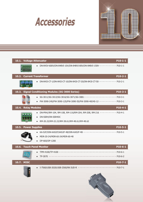
P10-1-1●DN-843V-600V/DN-848VI-10V/DN-848VI-80V/DN-848VI-150V- - - - - - - - - - - - P 10-1-1Current P10-2-1●DN-843I-CT-1/DN-843I-CT-10/DN-843I-CT-20/DN-843I-CT-50 - - - - - - - - - - - - P 10-2-1P10-3-1●SG-3011/SG-3013/SG-3016/SG-3071/SG-3081 - - - - - - - - - - - - - - - - - - - - - - P 10-3-1 ●PW-3090-24S/PW-3090-12S/PW-3090-5S/PW-3090-4824S-12 - - - - - - - - - - - - P 10-3-1Relay Modules P10-4-1●DN-PR4//RM-104, RM-108, RM-116/RM-204, RM-208, RM-216 - - - - - - - - - - - P 10-4-1 ●DN-SSR4/DN-SSR4DC●RM-20.22/RM-22.22/RM-38.61/RM-48.61/RM-48.62Power Supplies P10-5-1●KA-52F/DIN-KA52F/KA52F-48/DIN-KA52F-48 - - - - - - - - - - - - - - - - - - - - - - - P 10-5-1 ●MDR-20-24/MDR-60-24/MDR-60-48 ●DP-660/DP-1200P10-6-1●TPM-4100/TP-4100 - - - - - - - - - - - - - - - - - - - - - - - - - - - - - - - - - - - - - - - P 10-6-1 ●TP-3070 - - - - - - - - - - - - - - - - - - - - - - - - - - - - - - - - - - - - - - - - - - - - - - P 10-6-2MISC P10-7-1●I-7560/USB-2020/USB-2560/RK-3UD-R - - - - - - - - - - - - - - - - - - - - - - - - - - P 10-7-1AccessoriesProfessional Provider of High Quality I ndustrial C omputer P roducts and D ata A cquisition S ystems Vol. PAC 2.0.0A c c e s s o r i e s101Vout1GND Vout2GND Vout3GND+Vs GND F .G.NC Vin 1 -Vin 1+NC Vin 2 -Vin 2+NC Vin 3 -Vin 3+Vin 1 -Vin 1+Vin 2 -Vin 2+Vin 3 -Vin 3+Vin 4 -Vin 4+Vin 5 -Vin 5+Vin 6 -Vin 6+Vin 7 -Vin 7+Vin 8 -Vin 8++Vs GND F .G.Vout1 +OP Amp1OP Amp2OP Amp3OP Amp4OP Amp5OP Amp6OP Amp7OP Amp8Vout1 -Vout2 +Vout2 -Vout3 +Vout3 -Vout4 +Vout4 -Vout5 +Vout5 -Vout6 +Vout6 -Vout7 +Vout7 -Vout8 +Vout8 -DN-843V-600VDN-848VI-10V/DN-848VI-80V/DN-848VI-150V10.1. Voltage AttenuatorThe DN-800V series are voltage input attenuator . The maximum input range is from ±80 V to +/- 600 V and can be attenuated to ±10 V . The "I" version provide 3000 V DC intra-modules isolation and 3000 V DC channel to channel isolation to avoid the noise interference from inputs to outputs or channel to channel. It can be used with the analog input modules such as I-7017 and I-87017 etc. to measure the high voltage.DN-848VI-80VDN-848VI-150VAC/DC Source InputHigh Voltage Input Measurement Linear Attenuation Ratio High Input ImpedanceChannel to Channel Isolation forDN-848VI-10V , DN-848VI-80V and DN-848VI-150V 4 kV ESD Protection 3 kV Surge Protection RoHS ComplianceOperating Temperature: -25 ~ +75°C Easily Wire ConnectionDN-848VI-10VDN-843V-600V IntroductionApplicationsAppearanceProgrammable Automation Controller Products10-1-2Website:E-mail:*******************.PAC2.0.00Accessories101General Channels 8883Input Type AC/DC VoltageInput Range +/- 10 V pp+/- 80 V pp+/- 150 V pp+/- 600 V ppOutput Range +/- 10 V pp Accuracy1% of FSRChanel to Channel Isolation Yes, 3000 V DC-Bandwidth 30 KHz100 KHzInput Impedance> 1 M ΩIntra-module Isolation, Input to Output 3000 V DC -EMS Protection ESD (IEC 61000-4-2)+/- 4 kV contact for power line, input and output channels , +/- 8 kV air for random pointSurge (IEC 61000-4-5)+/- 3 kV for power linerPower Input Input Range +10 ~ +30 V DCPower Consumption 9.2 W9.2 W9.2 W0.56 WMechanicalDimensions (W x L x H)122 mm x 174 mm x 33 mm122 mm x 174 mm x 24.5 mmInstallation DIN-Rail MountingEnvironment Operating Temperature -25 ~ + 75°C Storage Temperature -30 ~ +75°CHumidity10 ~ 90% RH (non-condensing)8-channel 10 V Voltage Attenuator (RoHS)8-channel 80 V Voltage Attenuator (RoHS)8-channel 150 V Voltage Attenuator (RoHS)3-channel 600 V Voltage Attenuator (RoHS)MDR-20-24 CR24 V/1 A, 24 W Power Supply with DIN-Rail Mounting (RoHS)I-7017-G CR 8-channel Analog Input Module (RoHS)I-87017-G CR 8-channel Analog Input Module (RoHS)Selection GuideDN-84-x xx xxx Number of Channels 3: 3 channels 8: 8 channelsV: VoltageI: Channel to channel IsolationInput Voltage RangeDimensions (Units: mm)Bottom View Top View Bottom ViewTop View Left View Front View Rear ViewRight View Left View Front View Rear ViewRight View Speci fi cationsOrdering InformationAccessoriesProfessional Provider of High Quality I ndustrial C omputer P roducts and D ata A cquisition S ystems Vol. PAC 2.0.00102A c c e s s o r i e sDN-843I-CT-20DN-843I-CT-50DN-843I-CT-10DN-843I-CT-1 10.2. Current TransformerThe maximum input range is from ±1 A to +/- 50 A and can be attenuated to from ±1.6 V to ±10 V . The "I" version provide 3000 V DC intra-modules isolation and 3000 V DC channel to channel isolation to avoid the noise interference from inputs to outputs or channel to channel. It can be used with the analog input modules such as I-7017 and I-87017 etc. to measure the high current.AC/DC Source Input Linear Attenuation RatioHigh Current Input MeasurementIsolation InputChannel to Channel Isolation4 kV ESD Protection RoHS ComplianceOperating Temperature: -25 ~ +75°C Easily Wire ConnectionInstallationCh1 Current InputCh2 Current InputCh3 Current Input24 V DCCh1 OutputCh2 OutputCh3 OutputF.G. IntroductionApplicationsProgrammable Automation Controller Products10-2-2Website:E-mail:*******************.PAC2.0.00Accessories102General Channels 3Input Type AC/DC CurrentInput Range +/- 1 A+/- 10 A+/- 20 A+/- 50 AOutput Type AC/DC VoltageOutput Range +/- 1.6 V pp+/- 10 V pp+/- 10 V pp+/- 4 V ppCT Type Solid Core (closed)Accuracy1% of FSR Chanel to Channel IsolationYes, 3000 V rmsIntra-module Isolation, Input to Output 3000 V DC Bandwidth 50 KHz Input Impedance > 1 M ΩEMS Protection ESD (IEC 61000-4-2)+/- 4 kV contact for power line, input and output channels, +/- 8 kV air for random pointPower Input Input Range +10 ~ +24 V DCPower Consumption 1.2 WMechanicalDimensions (W x L x H)148 mm x 83 mm x 39 mmInstallation DIN-Rail Mounting Environment Operating Temperature -25 ~ + 75°C Storage Temperature -30 ~ +75°CHumidity10 ~ 90% RH (non-condensing)3-channel 1 A Current Transformer (RoHS)3-channel 10 A Current Transformer (RoHS)3-channel 20 A Current Transformer (RoHS)3-channel 50 A Current Transformer (RoHS)MDR-20-24 CR24 V/1 A, 24 W Power Supply with DIN-Rail Mounting (RoHS)I-7017-G CR 8-channel Analog Input Module (RoHS)I-87017-G CR8-channel Analog Input Module (RoHS)DN-84--xxxx xC: CurrentCT: Current TransformerInput Current RangeBottom ViewTop ViewLeft ViewFront ViewRight ViewNumber of Channels3: 3 channelsSelection GuideDimensions (Units: mm)Speci fi cationsOrdering InformationAccessoriesI C P roducts and D ata A cquisition S ystems Vol. PAC 2.0.00103A c c e s s o r i e s10.3. Signal Conditioning Modules (SG-3000 Series)DescriptionSG-3016SG-3071SG-3081PicturesAnalog Input Channel 11111Wiring Differential 2/3/4 wiresDifferential Differential Differential Signal ThermocoupleRTDStrain GaugeVoltage Current Type Type J, K, T , E, R, S, B, N, C, L,M, L2Pt100 α=0.00385, Pt100α=0.003916, Ni 120, Pt1000α=0.00385±10 mV , ±20 mV , ±30 mV ,±50 mV , ±100 mV ±5 V ,±10 V 0 ~ 20 mA, 4 ~ 20 mAResolution 12-bit 12-bit ---Accuracy ±0.2% of FSR±0.1% of FSR±0.1% of FSR±0.1% of FSR±0.1% of FSRInput Impedance 1.8 M Ω-- 1.6 M Ω250 ΩExcitation Voltage --0 ~ 10 V--Analog Output Channel 11111Current Output 0 ~ 20 mA 0 ~ 20 mA, 4 ~ 2 0mA 0 ~ 20 mA0 ~ 20 mA, 4 ~ 20 mA0 ~ 20 mA, 4 ~ 20 mA Voltage output 0 ~ 10 V0 ~ 5 V , 0 ~ 10 V±5 V , ±10 V , 0 ~ 5 V , 0 ~ 10 V±5 V , ±10 V0 ~ 5 V , 0 ~ 10 VSystem 3-way Isolation 1000 V DC Power Input 10 ~ 30 V DCPower Consumption 1.44 W1.2 W1.44 W 1.8 W1.61 WOperating Temperature -25 ~ +75°CDimensions (W x H x D)25 mm x 114 mm x 71 mmPW-3090-5SPW-3090-4824S-12PicturesInput 18 ~ 36 V (non-regulated)18 ~ 36 V (non-regulated)18 ~ 36 V (non-regulated)48 V (non-regulated)Output ********(Max.)********(Max.)5 V @ 2 A (Max.)********(Max.)Isolation 1000 V DCEf fi ciency83% Typical Operating Temperature -25 ~ +75°CDimensions (W x H x D)25 mm x 114 mm x 71 mmSG-3000 series signal conditioning modules are used to accept wide range of input signals, such as voltage, current, temperature (thermocouple and RTD) and provide 0 ~ 10 V DC , 0 ~ 20 mA, 4 ~ 20 mA output signals. It gives following good features for industrial applications • 3-way (power/input/output) isolation (1000 V DC )• Wide operating temperature (-25 ~ +75°C)• DIN-Rail mounting• Input and output connectors on the opposite side • Signal range con fi gureable by swtichIntroductionApplicationsProgrammable Automation Controller Products10-4-1Website:E-mail:*******************.PAC2.0.00Accessories104RM-38.61RM-48.61RM-48.62PicturesRelay Finder 20.22.9.024.4000Finder 22.22.9.024.4000Finder 34.51.7.024.0010FINDER - 40.61.7.024.0000FINDER - 44.62.7.024.0000Type Step RelayPower RelayChannel 1ContactForm A (DPST)Form A (DPST)Form C (SPDT)Form C (SPDT)Form C (SPDT)Operating Voltage Range 230 V AC 230 V AC 250 V AC 250 V AC 250 V AC Max. Load Current 16 A 20 A 6 A 16 A 10 A Operate Time 15 ms 15 ms 5 ms 7 ms 7 ms Release Time 8 ms8 ms3 ms 3 ms3 msLED Indicator -MechanicalDimensions (W x L x D)17.5 mm x 84 mm x 62.7 mm 76.5 mm x 6.5 mm x 89 mm75 mm x 15.5 mm x 78.5 mmInstallationDIN-Rail MountingNote1: RM-38.61: 5 pcs in one packageRM-48.61: 4 pcs in one package RM-48.62: 4 pcs in one packageNote2: RM-38-093.20is a 20-way jumper link for RM-38.61DN-SSR4PicturesRelay A5P-204UD3P-054Type Solid-State Relay Channel 4 channels ContactForm A (SPST)Operating Voltage Range 250 V AC /30 V DC50 V DCMax. Load Current 4 AOperate Time 1/2 Cycle + 1ms and below 0.5 ms and below (Resistance load)Release Time 1/2 Cycle + 1ms and below0.5 ms and below (Resistance load)LED Indicator Yes (for Relay status)MechanicalDimensions (W x L x D)101 mm x 77 mm x 66 mmInstallationDIN-Rail MountingPicturesRelay VE-24H5-K FINDER - 40.61.7.024.0000FINDER - 44.52.7.024.0000Type Power Relay Channel 4RM-104: 4 channels RM-108: 8 channels RM-116: 16 channels RM-204: 4 channels RM-208: 8 channels RM-216: 16 channels ContactForm C Form C (SPDT)Form C (DPDT)Operating Voltage Range 250 V AC /30 V DC250 V AC 250 V AC Max. Load Current 5 A 16 A 6 A Operate Time 10 ms (Typical)7 ms (Typical)8 ms (Typical)Release Time 5 ms (Typical)3 ms (Typical) 5 ms (Typical)LED Indicator Yes (for Relay status)MechanicalDimensions (W x L x D)96 mm x 103 mm x 34 mmRM-104: 79 mm x 87 mm x 63 mm RM-108: 135 mm x 87 mm x 63 mm RM-116: 270 mm x 87 mm x 63 mmRM-204: 90 mm x 87 mm x 63 mm RM-208: 169 mm x 87 mm x 63 mm RM-216: 327 mm x 87 mm x 63 mmInstallationDIN-Rail Mounting10.4. Relay ModulesI ndustrial C omputer P roducts and D ata A cquisition S 105A c c e s s o r i e s10.5. Power SuppliesModelsKA-52F DIN-KA52F KA-52F-48DIN-KA52F-48Input Range 100 ~ 250 V AC Frequency 50 ~ 60 HzOutput Power 24 V DC /1.04 A Max., 25 W48 V DC /0.52 A Max., 25 WMechanicalDimensions(W x H x D, Units: mm)54 x 93 x 36 68 x 107 x 50 54 x 93 x 36 68 x 107 x 50 Installation No-mountingDIN-Rail MountingNo-mountingDIN-Rail MountingEnvironmentalOperating Temperature 0 ~ +50°C Storage Temperature-20 ~ +85°CModelsMDR-20-24MDR-60-24MDR-60-48Input Range 100 ~ 250 V AC Frequency 50 ~ 60 HzOutput Power 24 V DC /1 A Max., 24 W24 V DC /2.5 A Max., 60 W48 V DC /1.25 A Max., 60 WMechanicalDimensions (W x H x D)22.5 mm x 90 mm x 100 mm 40 mm x 90 mm x 100 mm 40 mm x 90 mm x 100 mmInstallation DIN-Rail MountingEnvironmental Operating Temperature -20 ~ +70°C Storage Temperature-20 ~ +85°CModelsDP-660DP-1200Input Range 100 ~ 250 V AC Frequency 50 ~ 60 HzOutputPower 24 V DC /2.5 A Max., 60 W and5 V DC /0.5 A Max., 2.5 W24 V DC /5.0 A Max., 120 WMechanicalDimensions (W x H x D)44 mm x 145 mm x 158 mm 65 mm x 111 mm x 125 mmInstallation DIN-Rail MountingEnvironmentalOperating Temperature 0 ~ +50°C -10 ~ +70°C Storage Temperature-20 ~ +85°C-25 ~ +85°CKA-52F CR 24 V DC /1.04 A, 25 W Power Supply (RoHS)DIN-KA52F CR 24 V DC /1.04 A, 25 W Power Supply with DIN-Rail Mounting (RoHS)KA-52F-48 CR 48 V DC /0.52 A, 25 W Power Supply (RoHS)DIN-KA52F-48 CR48 V DC /0.52 A, 25 W Power Supply with DIN-Rail Mounting (RoHS)MDR-20-24 CR 24 V DC /1 A, 24 W Power Supply with DIN-Rail Mounting (RoHS)MDR-60-24 CR 24 V DC /2.5 A, 60 W Power Supply with DIN-Rail Mounting (RoHS)MDR-60-48 CR48 V DC /1.25 A, 60 W Power Supply with DIN-Rail Mounting (RoHS)DP-660 CR 24 V DC /2.5 A, 60 W and 5 V DC /0.5 A, 2.5 W Power Supply with DIN-Rail Mounting (RoHS)DP-1200 CR24 V DC /5.0 A, 120 W Power Supply with DIN-Rail Mounting (RoHS)KA-52F/DIN-KA52F KA52F-48/DIN-KA52F-48MDR-20-24MDR-60-24MDR-60-48DP-660DP-1200KA-52F KA-52F-48MDR-60-24/MDR-60-48DP-1200MDR-20-24DP-660DIN-KA52F DIN-KA52F-48Speci fi cationsSpeci fi cationsSpeci fi cationsOrdering InformationOrdering InformationOrdering InformationProgrammable Automation Controller Products10-6-1Website:E-mail:*******************.PAC2.0.00Accessories106TPM-4100TP-410010.6. Touch Panel MonitorTPM-4100/TP-410010.4" Touch Panel Monitor10.4" LCD supports 800 x 600 resolution Resistive Touch Panel Full-function OSD controlDriver Support: Windows 2k/XP/Vista/7/WESWinCE 5.0/6.0 LED backlight technology Aluminum Casing for TPM-4100 IP65 Comlipant Front PanelWide operating temperature: -25 ~ +75°CTPM-4100TP-4100Display Size 10.4”Resolution 800 x 600Max. Color 16.7 M Brightness (cd/m2)320Contrast Ratio 500 : 1Viewing Angle (H/V)140/130Backlight Life (hrs)50,000Touch Panel 4-wire5-wireanalog resistive, RS-232 or USB1.1 (Type B) interfaceInput SignalVGA (Analog RGB)MMI (Man Machine Interface)OSD Control Functions: Brightness, Contrast, Phase, Horizontal Position,Vertical Position and SharpnessPower Switch YesLED Indicators Power , Display signal is detectedPower Input Range +12 ~ 48 V DCPower Consumption 8.5 WMechanical MaterialAluminumPlasticDimensions (W x L x H)293 mm x 231 mm x 53 mm290 mm x 228 mm x 53 mm Installation Panel MonutingPanel Monuting, VESA (75 × 75) MountingIngress Protection Front panel: IP65Environmental Operating Temperature -25 ~ +75°C Storage Temperature -30 ~ +80°CAmbient Relative Humidity10 ~ 90% RH (non-condensing)10.4" (800 x 600) resistive touch panel monitor with RS-232 or USB interfaceAccessories: Power supply, VGA cable, RS-232 cable, USB cable, Mounting clamps and screws TP-4100 with Aluminum Casing273210.8TPM-4100 Dimensions (Units: mm)Speci fi cationsAppearanceOrdering InformationUSB USBOSD OSDRS-232RS-232VGAVGA Power Switch Power Switch VESA (75 × 75) Mounting12 ~ 48 DC IN12 ~ 48 DC INI ndustrial C omputer P roducts and D ata A cquisition S ystems Vol. PAC 2.0.00106A c c e s s o r i e sTP-30707" Touch Panel Monitor7" LCD supports 800 x 480 resolution Resistive Touch Panel Full-function OSD controlDriver Support: Windows 2k/XP/Vista/7/WESWinCE 5.0/6/0 LED backlight technology IP65 Comlipant Front PanelWide operating temperature: -20 ~ +70°CTP-3070Display Size 7”Resolution 800 x 480Brightness (cd/m2)320Contrast Ratio 500 : 1Viewing Angle (H/V)140/120Backlight Life (hrs)20,000Touch Panel 4-wire, analog resistive, RS-232 or USB1.1 (TypeB) interfaceInput SignalVGA (Analog RGB)MMI (Man Machine Interface)OSD Control Functions: Brightness, Contrast, Clock, Phase, Horizontal Position, Vertical Position and SharpnessPower Switch YesLED Indicators Power , Display signal is detectedPower Input Range +12 ~ 48 V DCPower Consumption 5 WMechanicalDimensions (W x L x H)213 mm x 148 mm x 44 mmCasingPlastic Ingress Protection Front panel: IP65Environmental Operating Temperature -20 ~ +70°C Storage Temperature -30 ~ +80°CAmbient Relative Humidity10 ~ 90% RH (non-condensing)7" (800 x 480) resistive touch panel monitor with RS-232 or USB interfaceAccessories: Power supply, VGA cable, RS-232 cable, USB cable, Mounting clamps and screwsDimensions (Units: mm)Speci fi cationsOrdering InformationProgrammable Automation Controller Products10-7-1Website:E-mail:*******************.PAC2.0.00Accessories 107InterfaceUSBCompatibility: USB 1.1 and 2.0 standards RS-232TxD, RxD, RTS, CTS, DSR, DTR, DCD, RI and GND; non-isolated Baud Rate300 ~ 115200 bps DriverWindows 98/ME/2000/XP/Vista (32/64-bit)/7 (32/64-bit)/LinuxMechanicalDimensions (W x H x D)33 mm x 60 mm x 15 mm Environmental Operating Temperature-25 ~ +75°C Storage Temperature -30 ~ +75°CInterfacePortsUpstream x 1 (Type B); Downstream x 4 (Type A)CompatibilitySpeci fi cation Rev. 2.0/1.1/1.0Transfer Speed480 Mbit/s-high speed mode Input Voltage Range+10 ~ +30 V DCMechanicalDimensions (W x H x D)33 mm x 107 mm x 78 mm InstallationDIN-Rail Mounting Environmental Operating Temperature -0 ~ +70°C Storage Temperature -20 ~ +80°CMechanical Dimensions (W x H x D)481 mm x 132 mm x 125 mm USB-2020 CR USB Audio Device (RoHS)RK-3UD-R 19" Rack Mounting Kit, 3U I-7560 CR USB to RS-232 Converter (RoHS)USB-2560 CR4-port Industrial USB 2.0 Hub (RoHS)USB-2560/S CR 4-port Industrial USB 2.0 Hub (RoHS) with GPSU06U-6 (Power Supply)RK-3UD-R I-7560InterfaceOutput ChannelsMono, Stereo (L + R)Input ChannelsMono, Stereo (L + R)ButtonHID volume up, volume down and Mute Input Voltage Range+10 ~ +30 V DCMechanicalDimensions (W x H x D)33 mm x 107 mm x 78 mm Installation DIN-Rail Mounting Environmental Operating Temperature-25 ~ +75°C Storage Temperature -40 ~ +85°C 10.7. MISC Speci fi cationsSpeci fi cationsSpeci fi cationsSpeci fi cationsOrdering InformationOrdering InformationOrdering Information Ordering Information USB to RS-232 Converter USB-2020USB-2560USB Audio Device 4-Port Industrial USB 2.0 Hub19" Rack Mounting Kit, 3UiP-84112-4-3 iP-88112-4-3 iP-84412-4-3 iP-88412-4-3 iP-8441-FD2-4-3 iP-8841-FD2-4-3 iP-84172-4-5Model Name PageiP-84472-4-5iP-88172-4-5iP-88472-4-5I-87005W5-2-1I-87013W5-2-1I-87015PW5-2-2I-87015W5-2-2I-8014W5-2-3I-8017DW5-2-3I-8017HCW5-2-3I-8017HW5-2-3I-8024DW5-2-3I-8024W5-2-3I-87017DW5-2-4I-87017RCDW5-2-4I-87017RCDW-AI5-2-4I-87017RCW 5-2-4I-87017RW 5-2-4I-87017W5-2-4I-87017W-A55-2-4I-87017ZW5-2-4I-87018PW5-2-5I-87018RW5-2-5I-87018W5-2-5I-87018ZW5-2-5I-87019PW5-2-6I-87019RW5-2-6I-87019ZW5-2-6I-87024W 5-2-7I-87024CW5-2-7I-87024DW 5-2-7I-87024RW 5-2-7I-87024UW 5-2-7I-87028CW5-2-7I-8040PW5-3-1I-8040W5-3-1I-8046W5-3-1I-8048W5-3-1I-8051W5-3-1I-8052W5-3-1I-8053W5-3-1I-8053PW5-3-1Model Name PageI-8058W5-3-1I-87040W5-3-2I-87040PW5-3-2I-87046W5-3-2I-87051W5-3-2I-87052W5-3-2I-87058W5-3-2I-87059W5-3-2I-87053W5-3-3I-87053PW5-3-3I-87053W-A55-3-3I-87053W-AC15-3-3I-87053W-E55-3-3I-8037W5-3-4I-8041W5-3-4I-8041RW5-3-4I-8041AW5-3-4I-8056W5-3-4I-8057W5-3-4I-8057RW5-3-4I-8057PW5-3-4I-8060W5-3-4I-8064W5-3-4I-8068W5-3-4I-8069RW5-3-4I-8069W5-3-4I-87037W5-3-5I-87041W 5-3-5I-87057W5-3-5I-87057PW5-3-5I-87061W5-3-5I-87064W5-3-5I-87065W5-3-5I-87066W5-3-5I-87068W5-3-5I-87069W5-3-5I-87069PW5-3-5I-8042W5-3-6I-8050W5-3-6I-8054W5-3-6I-8054RW5-3-6I-8055W5-3-6Model Name PageI-8063W5-3-6I-87042W5-3-7I-87054W5-3-7I-87055W5-3-7I-87063W5-3-7I-8026PW5-4-1I-87016W5-4-1I-87026PW5-4-1I-87089W/S5-5-1I-8084W5-6-1I-8088W5-6-1I-87082W5-6-1I-87084W5-6-1I-87088W5-6-1I-8092F5-7-1I-8093W5-7-1I-80945-7-1I-8094A5-7-1I-8094F5-7-1I-8094H5-7-1I-75105-8-1I-7510A5-8-1I-7510AR5-8-1I-75135-8-1I-7514U5-8-1I-7520 5-8-1I-7520A5-8-1I-7520AR5-8-1I-7520R5-8-1I-7520U45-8-1I-75515-8-1I-8112iW5-8-1I-8114iW5-8-1I-8114W5-8-1I-8142iW5-8-1I-8144iW5-8-1I-25325-9-2I-25335-9-2I-75305-9-2I-7530A5-9-2I-7530A-MR5-9-2I-7530-FT5-9-2Model IndexI-75315-9-2 I-75325-9-2 I-7540D5-9-2 I-7540D-MTCP5-9-2 I-7540D-WF5-9-2 I-75655-9-2I-7565-H15-9-2 I-7565-H25-9-2 I-8120W5-9-2 I-8123W5-9-2 I-8124W5-9-2 I-871235-9-2 I-871245-9-2 I-87H17W5-10-1 I-87H24W5-10-1 I-75475-10-1 I-75675-10-1 I-75705-10-1 I-8172W5-11-1 I-8212W5-12-1 I-8212W-3GWA5-12-1 I-8213W5-12-1 I-8213W-3GWA5-12-1 I-87211W 5-12-1 iP-8441-MTCP6-3-2 iP-8841-MTCP6-3-2 I-7188XG7-1-6 I-7188XGD7-1-6 I-71887-1-9 I-7188D7-1-9 I-7188XA7-1-9 I-7188XAD7-1-9 I-7188XB7-1-9 I-7188XBD7-1-9 I-7188XC7-1-9 I-7188XCD7-1-9 I-7188EA7-1-11 I-7188EAD7-1-11 I-7188EX7-1-11 I-7188EXD7-1-11 I-756010-7-1 iDCS-88309-1-3USB-87P25-4-2USB-87P45-4-2USB-87P85-4-2USB-202010-7-1USB-256010-7-1WP-8131 2-2-3WP-84312-2-3WP-88312-2-3WP-81412-2-3WP-84412-2-3WP-88412-2-3WP-80512-2-3WP-83512-2-3WP-87512-2-3WP-81372-2-6WP-84372-2-6WP-88372-2-6WP-81472-2-6WP-84472-2-6WP-88472-2-6WP-80572-2-6WP-83572-2-6WP-87572-2-6WP-81392-2-11WP-84392-2-11WP-88392-2-11PROFI-82556-6-2PROFI-84556-6-2PROFI-88556-6-2PW-3090-5S10-3-1PW-3090-12S10-3-1PW-3090-24S10-3-1PW-3090-4824S-1210-3-1USB-87P15-4-2iDCS-8830R9-1-3PROFI-81556-6-2XP-8349-Atom-CE62-1-14 XP-8749-CE62-1-14 XP-8749-Atom-CE62-1-14 X1017-2-3 X1067-2-3 X1077-2-3 X1107-2-3 X1117-2-3 X2007-2-3 X2027-2-3 X2037-2-3 X3027-2-3 X3037-2-3 X3047-2-3 X3057-2-3 X3087-2-3 X3107-2-3 X3247-2-3 X5037-2-3 X5047-2-3 X5057-2-3 X5067-2-3 X5077-2-3 X5087-2-3 X5097-2-3 X5107-2-3 X510-1287-2-3 X5117-2-3 X5187-2-3 X6037-2-3 X6077-2-3 X6087-2-3 X7027-2-3 X7037-2-3 XV1168-4-1 XV107Ai8-4-2 XV107i8-4-2 XV110i8-4-2 XV111Ai8-4-2 XV111i8-4-2 XW1078-4-2 XW107i8-4-2μPAC-51078-1-7μPAC-5107D8-1-7μPAC-52078-1-7μPAC-5207D8-1-7μPAC-53078-1-7μPAC-5307D8-1-7μPAC-55078-1-7μPAC-5507D8-1-7 XW110i8-4-2XV304i8-4-3XV305i8-4-3XV308i8-4-3XV310i8-4-3XW3048-4-4XW3108-4-4XW310C8-4-4XW5068-4-5XW5078-4-5XW5088-4-5XW5098-4-5XW511i8-4-5XW5148-4-5μμPAC-7186EX 7-1-4μPAC-7186EXD 7-1-4μPAC-7186EX-FD 7-1-4μPAC-7186EXD-FD 7-1-4μPAC-7186EX-SM 7-1-4μPAC-7186EXD-SM 7-1-4μPAC-7186EG7-1-6μPAC-7186EG-D7-1-6μPAC-50018-1-6μPAC-5001D8-1-6μPAC-5001-FD8-1-6μPAC-5001D-FD8-1-6μPAC-5101 8-1-6μPAC-5101D 8-1-6μPAC-52018-1-6μPAC-5201D8-1-6μPAC-53018-1-6μPAC-5301D8-1-6μPAC-55018-1-6μPAC-5501D8-1-6μPAC-5801 8-1-6μPAC-5801D8-1-6μPAC-59018-1-6μPAC-5901D8-1-6μPAC-50078-1-7μPAC-5007D8-1-7WP-81492-2-11WP-84492-2-11WP-88492-2-11WP-80592-2-11WP-83592-2-11WP-87592-2-11WP-51418-2-4WP-5141-OD8-2-4WP-52318-2-6WP-5231-2G8-2-6WP-5231-3G8-2-6WP-5231-GPS8-2-6WP-5231-WF8-2-6WP-5231-ZH8-2-6WP-5231-ZS8-2-6WP-51478-2-8WP-5147-OD8-2-8WP-51498-2-11WP-5149-OD8-2-11XXP-8041 2-1-5XP-8141-Atom2-1-5XP-83412-1-5XP-8341-Atom2-1-5XP-87412-1-5XP-8741-Atom2-1-5XP-8041-CE62-1-7XP-8141-Atom-CE62-1-7XP-8341-CE62-1-7XP-8341-Atom-CE62-1-7XP-8741-CE62-1-7XP-8741-Atom-CE62-1-7XP-8047-CE62-1-9XP-8147-Atom-CE62-1-9XP-8347-CE62-1-9XP-8347-Atom-CE62-1-9XP-8747-CE62-1-9XP-8747-Atom-CE62-1-9XP-8049-CE62-1-14XP-8149-Atom-CE62-1-14XP-8349-CE62-1-14 Model Index。
ATN产品硬件介绍

Copyright©2012Huawei Technologies Co., Ltd. All Rights Reserved.
愿景、使命、独特价值-ATN LMT
愿 景
提供客户渴望的移动承载网络,铸就 业界最佳品牌 聚焦客户,构筑高质量的ATN产品, 支撑市场拓展与交付,保障网络零事故 聚焦产品运维工作,致力于ATN的网上维护和大局交付 聚焦维护版本质量建设,主动的版本生命周期管理 贴近客户,把握价值需求,持续提升产品竞争力 建设运维专家队伍、流程和知识体系,打造ATN维护的能力中心
接口功能
时钟
支持PHY层的内环回和外环回。
支持端口环回自动解除。默认环回解除时间为5min 支持同步以太。 支持SSM协议。 支持IEEE 1588 V2协议。 支持1588 ACR时钟。
工作状态灯 (STAT) 亮(绿色) 亮(红色) 亮(橙色) 灭
指示灯说明 单板工作正常 单板硬件故障 单板注册失败 单板供电异常
CLK
TOD ALARM 微动开关 12345
外时钟输入输出
外时间输入输出 检测周围环境(机柜中的电源设备、散热设备等)告警量,提供3路输入1路输出(预留接口) 提供两个微动开关。在拔出单板,拉动扳手时会触发两个微动开关,从而触发主备倒换。
3. 时钟状态指示灯SYNC 亮(绿色) 亮(红色) 4. 交换主备指示灯ACTX 指示灯说明 未配置时钟或时钟工作正常 时钟源丢失 指示灯说明 表示交叉/时钟主用状态 表示交叉/时钟备用状态 指示灯说明 表示主控主用状态 主机配臵批量备份过程中 表示主控备用状态
STAT ALM
亮(红色) 亮(橙色) 亮(黄色) 灭
ATN产品基础
安装环境规范
商品说明书:ATLAS SOUND AT 系列商业抑制器

©2011 A t l a s S o u n d L .P . A l l r i g h t s r e s e r v e d . A t l a s S o u n d a n d S t r a t e g y S e r i e s a r e t r a d e m a r k s o f A t l a s S o u n d L .P . A l l o t h e r t r a d e m a r k s a r e t h e p r o p e r t y o f t h e i r r e s p e c t i v e o w n e r s . A T S 001063 R e v D 10/13Commercial AttenuatorsAT Series, E408 SeriesFeatures• M odels Feature a Range of Attenuation Steps (1.5dB or 3dB Steps) as Well as Continuous to Meet Application and Budget Requirements • W all Plates are Stainless Steel with Stamped and Filled or Screen Printed Dial Scale, and a Skirted Black Knob (White and Ivory Plastic Plates with Matching Skirted Knobs Also Available in Decora Style-D Series Only)• P opular Rack Mount Attenuator Versions are Available on the AT and E408 Series for Mounting on to Blank Panels in Equipment Cabinets• All AT Models Mount into Most 1-Gang E.O. Boxes. (23⁄4" Deep)• AT and E408 Series are UL ListedGenenal DescriptionAT Series Industry Standard Auto Transformer. High-quality auto transformer series provides the advantages of excellent frequencyresponse, low insertion loss and reliable performance for volume control application in 25V/70.7V systems. Attenuation is accomplished in ten make before break steps plus positive Off position. (No stop between maximum and Off position to prevent switch damage). Contacts are silver plated for noise-free operation. Features a removable terminal block. Includes stainless steel plate, with stamped and filled or screen printed dial scale and a skirted black knob. (White and ivory plastic plates with matching skirted knobs also available in Decora style-see AT model description chart).E408 Auto Transformer with Precision Level Control. Specially designed for attenuation in masking and sound reinforcement systems where fine tuning of level control is required. Employs a ten-position, non-shorting rotary switch without stop. Attenuation rate is 1.5dB per step. (All other specifications are the same as the AT Series including the UL listing).PA Series Priority Paging Option. Priority paging feature by-passes the effect of the attenuator to provide program level selection of individual emergency and paging signals at the amplifier. Option isavailable on all AT attenuators. The SPDT relay is operated with 24VDC at 10mA. Includes protective relay cover to ensure lasting trouble-free performance. Terminations to the relay and attenuator are made via a removable terminal block. (All other specifications except for dimensions are the same as selected AT models).RM Series Rack Mount Option. For attenuation convenience of rack-mounted equipment in cabinets and consoles, the AT, E408Series attenuators are available without mounting plate for rack panel installation. Attractive matte black polycarbonate dial scale overlay with adhesive backing replaces the mounting plate. Includes skirted black knob. Overlay size is 29 square (51mm). (To order, simply add RM after the selected attenuator model number. Example: AT10-RM or AT10-PARM.) (Dial scale overlays to retrofit existing installations are available, see Model HX23.)Replacement Knobs©2011 A t l a s S o u n d L .P . A l l r i g h t s r e s e r v e d . A t l a s S o u n d a n d S t r a t e g y S e r i e s a r e t r a d e m a r k s o f A t l a s S o u n d L .P . A l l o t h e r t r a d e m a r k s a r e t h e p r o p e r t y o f t h e i r r e s p e c t i v e o w n e r s . A T S 001063 R e v D 10/13Specfications AT10-(PA)Power Rating * 10 WattsUL ListingAttenuation Per Step 3dB Total Attenuation33dB**Insertion Loss .4dB Plate Size 1 gang Resistance NoneAT35-(PA)Power Rating *35 WattsUL ListingAttenuation Per Step 3dB Total Attenuation27dBInsertion Loss .6dB Plate Size 1 gang Resistance NoneAT100-(PA)Power Rating *100 WattsUL ListingAttenuation Per Step 3dB Total Attenuation27dBInsertion Loss .6dB Plate Size 1 gang Resistance NoneE408-100Power Rating *100 WattsUL ListingAttenuation Per Step 1.5dB Total Attenuation15dBInsertion Loss .6dB Plate Size 1 gang Resistance None* Continuous** These units have two steps of 6dB before off position.Note: Attenuation curve is steeper for a 25-volt lineArchitect and Engineer SpecificationsAT Series Attenuator(s) shall be Atlas Sound AT Series Model____________ auto transformer or approved equal. The power rating shall be __________ and attenuation range shall be _________dB. Attenuation per step for AT-____ shall be 8 steps of 3dB and 6dB each for the last two positions. Attenuator shall be a step type control with a positive off position. There shall be no stop between the maximum and off positions (AT Series only). Switch shall have silver plated contacts to eliminate noise and contact loss. All terminations must be made via a removable terminal block. Unit(s) shall be supplied with one of the following single gang face plates to be noted by model number suffix: Standard stain l ess steel faceplate (with dial scale to indicate attenuator position), Decora style plastic face plate-Ivory color, Decora style plastic face plate-White color. All models are designed to mount in a standard E.O. box.E408 UL Listed attenuator shall be Atlas Sound Model E408-100 auto transformer or approved equal. The power rating shall be 100W. The at t enu a tion per step shall be 1.5dB. Unit shall be a step type control with a positive off position. There shall be no stop between the maximum and off positions. Switch shall have silver plated contacts to elimi n ate noise and contact loss. The attenuator shall be mounted to a standard gang stainless steel wall plate which mounts to a standard E.O. box.RM Option Attenuator shall be Atlas Sound Model ____________ [(AT, E408 (-RM)] or ap p roved equal. Face plate shall be replaced by an adhesive matte black poly c ar b on a te dial scale escutcheon for attachment to a rack mount panel. Escutcheon size shall be 2" SQ.PA Option Specified AT Series attenuators include a priority relay. Relay shall be an SPDT, 24 VDC type securely mounted to the attenuator assembly wired at the factory. Relay shall include a protective cover.AT10 (dc) (-PA) (-RM)AT35 (dc) (-PA) (-RM)Faceplate Options:d = D - Decora Style FaceplateIvory and White inserts, trim ring and knobs icluded.If there is not the above 1 letter suffix, the attenuator is shipped with the standard stainless steel faceplate or is the RM version without a faceplate.©2011 A t l a s S o u n d L .P . A l l r i g h t s r e s e r v e d . A t l a s S o u n d a n d S t r a t e g y S e r i e s a r e t r a d e m a r k s o f A t l a s S o u n d L .P . A l l o t h e r t r a d e m a r k s a r e t h e p r o p e r t y o f t h e i r r e s p e c t i v e o w n e r s . A T S 001063 R e v D 10/13AT SeriesDimensional Specifications Plate Mounted AttenuatorsMODEL A B C D EAT10 41⁄2" 21⁄8" 23⁄4" 23⁄4" 13⁄4"AT10-PA 41⁄2" 21⁄8" 23⁄4" 23⁄4" 13⁄4"AT3541⁄2"21⁄8" 23⁄4" 23⁄4" 13⁄4"AT35-PA 41⁄2" 21⁄8" 23⁄4" 23⁄4" 13⁄4"AT10041⁄2"21⁄2" 23⁄4" 23⁄4" 13⁄4"AT100-PA 41⁄2" 21⁄2" 23⁄4" 23⁄4" 13⁄4"E408-100 41⁄2"25⁄8"23⁄4"23⁄4"13⁄4"©2011 A t l a s S o u n d L .P . A l l r i g h t s r e s e r v e d . A t l a s S o u n d a n d S t r a t e g y S e r i e s a r e t r a d e m a r k s o f A t l a s S o u n d L .P . A l l o t h e r t r a d e m a r k s a r e t h e p r o p e r t y o f t h e i r r e s p e c t i v e o w n e r s . A T S 001063 R e v D 10/13WIRING - AT SeriesEach terminal will hold up to 2-16AWG stranded wire.For larger wires or home run situations, a small length of wire and a wire nut are recommended.Attach wire according to label on terminal black as shown below (Non-PA Models will not have the "VDC+" and "VDC-" terminals).* Install the unit with the terminal block on top. This will ensure that theoff position is on the bottom.©2011 A t l a s S o u n d L .P . A l l r i g h t s r e s e r v e d . A t l a s S o u n d a n d S t r a t e g y S e r i e s a r e t r a d e m a r k s o f A t l a s S o u n d L .P . A l l o t h e r t r a d e m a r k s a r e t h e p r o p e r t y o f t h e i r r e s p e c t i v e o w n e r s . A T S 001063 R e v D 10/13Wiring - (-Pa) Priority AttenuatorsRelay SpecificationsCOIL VOLTAGE: 24VDC COIL CURRENT: 10MACONTACTS: S PDT-2AMP RatingRelay Has a Protective CoverPower Switching Req. For - Pa Attenuators。
南京普天10A控制器性能参数
希望这款控制器给你带来更实惠的功能一:光控(时控)模式:开灯照度10LUX,相当于目前长江中下游地区夏天晚7:30左右,(采用电池板光压照度法,开关灯时间更准确、更合理;0-255LUX可任意调,关灯照度默认为在开灯照度基础上再加10LUX;开灯照度设定后,也可以在光控基础上选择时控。
二:欠压保护功能:蓄电池电压低于欠压保护值时,控制器关闭两路负载,停止供电,如果继续放电,易造成蓄电池因为过放而损坏,所以欠压保护值国家强制标准为10.8V,(欠压保护值为10.0V-14.7V可选,建议设置为11.1V。
此保护功能不可以关闭)三:安全的雷电保护:通过TVS防雷管进行防雷,保证了相关组件的安全四:负载的短路保护、极性反接保护、负载过流保护:摒弃以前单独用保险丝进行保护,现已改成通过软件快速感应率先保护,更好的保护了相关器件不被损毁,省略了故障时人工换保险丝的麻烦。
五:反向放电保护:通过两路场管控制蓄电池对电池板反向放电,防止蓄电池容量损耗,保护更完善。
六:控制器对蓄电池的温度补偿:蓄电池有负温度特性,在常温下(25℃),每增加1℃,12V蓄电池电压降低0.014-0.018V左右,此款控制器将给予电压补偿,既保证蓄电池在恒压环境工作,延长其使用寿命;又保证其不会受夏日高温环境影响而导致使用时经常欠压断电。
(蓄电池埋于地下的,将随控制器赠送温度传感线)七:低压节能保护:蓄电池电压低于12V时,表示蓄电池所存电量已不足,此时控制器将一路灯关闭,保留另一路灯的照明,确保照明时间有效延长。
(低压保护值为12V-14.7V,也可选择关闭此保护功能)八:充电涓流保护:充电时,蓄电池在达到峰值电压后,如果继续高压充电容易造成蓄电池的失水或失控,如果停止充电蓄电池又无法饱和。
此款控制器在充到峰值电压后立即降压1V,然后进入涓流充电状态,保证了蓄电池可以稳定于饱满状态,同时又避免了失水或失控,类似于对蓄电池进行循环充,不仅高效的保护了蓄电池,还提升了蓄电池的充电次数,使用寿命更长。
APT60DQ120SG商品说明书

APT60DQ120SGDatasheet Ultrafast Soft Recovery Rectifier DiodeFinalApril 2018Contents1Revision History (1)1.1Revision A (1)2Product Overview (2)2.1Benefits (2)2.2Applications (2)3Electrical Specifications (3)3.1Absolute Maximum Ratings (3)3.2Electrical Performance (3)3.3Dynamic Characteristics (4)3.4Typical Performance Curves (4)3.5Reverse Recovery Overview (6)4Package Specification (7)4.1Package Outline Drawing (7)1Revision HistoryThe revision history describes the changes that were implemented in the document. The changes arelisted by revision, starting with the most current publication.1.1Revision ARevision A was published in April 2018. It is the first publication of this document.2Product OverviewFeaturesThe following are key features of the APT60DQ120SG device:Ultrafast recovery timesSoft recovery characteristicsLow forward voltageLow leakage currentAvalanche energy ratedRoHS compliant2.1BenefitsThe following are benefits of the APT60DQ120SG device:Higher switching frequencyLow switching lossesLow noise (EMI) switchingHigher reliability systemsIncreased system power density2.2ApplicationsThe APT60DQ120SG device is designed for the following applications: Power Factor Correction (PFC)Anti-parallel diodeSwitch-mode power supplyInverters/convertersMotor controllersFreewheeling diodeSwitch-mode power supplyInverters/convertersSnubber/clamp diode3Electrical SpecificationsThis section shows the electrical specifications for the APT60DQ120SG device.3.1Absolute Maximum RatingsThe following table shows the absolute maximum ratings for the APT60DQ120SG device.All ratings: T = 25 °C unless otherwise specified.CTable 1 • Absolute Maximum RatingsSymbol Parameter Ratings UnitV R Maximum DC reverse voltage1200VV RRM Maximum peak repetitive reverse voltage1200V RWM Maximum working peak reverse voltage1200I F(AV)Maximum average forward current (T = 103 °C, duty cycle = 0.5)C60AI F(RMS)RMS forward current87I FSM Non-repetitive forward surge current (T = 45 °C, 8.3 ms)J540E AVL Avalanche energy (1 A, 40 mH)20mJT , TJ STG Operating and storage temperature range–55 to 175°CT L Lead temperature for 10 seconds300The following table shows the thermal and mechanical characteristics of the APT60DQ120SG device.Table 2 • Thermal and Mechanical CharacteristicsSymbol Characteristic Min Typ Max UnitRθJC Junction-to-case thermal resistance0.40°C/WW T Package weight0.14oz4.0g 3.2Electrical PerformanceThe following table shows the static characteristics of the APT60DQ120SG device.Table 3 • Static CharacteristicsSymbol Characteristic Test Conditions Min Typ Max UnitV F Forward Voltage I = 60 AF 2.8 3.3VI = 120 AF 3.35I = 60 A, T = 125 °CF J 2.11I RM Maximum reverse leakage current V = 1200 VR100μAV = 1200 V, T = 125 °CR J500C J Junction capacitance V = 200 VR37pF3.3Dynamic CharacteristicsThe following table shows the dynamic characteristics of the APT60DQ120SG device.Table 4 • Dynamic CharacteristicsSymbol Characteristic Test ConditionsMin Typ Max Unit t rrReverse recovery timeI = 1 A, di /dt = –100 A/µs F F V = 30 V R T = 25 °CJ30nst rr Reverse recovery time I = 60 A, di /dt = –200 A/µs F F V = 800 V R T = 25 °CC 320 Q rr Reverse recovery change 630 nC I RRM Maximum reverse recovery current 5 A t rr Reverse recovery time I = 60 A, di /dt = –200 A/µs F F V = 800 V R T = 125 °CC 420 ns Q rr Reverse recovery charge 2810 nC I RRM Maximum reverse recovery current 12 A t rr Reverse recovery time I = 60 A, di /dt = –1000 A/µs F F V = 800 V R T = 125 °CC 190 ns Q rr Reverse recovery change 4415 nC I RRMMaximum reverse recovery current38A3.4Typical Performance CurvesThis section shows the typical performance curves for the APT60DQ120SG device.Figure 1 • Maximum Transient Thermal ImpedanceFigure 2 • Forward Current vs. Forward Voltage Figure 3 • trr vs. Current Rate of ChangeFigure 2 • Forward Current vs. Forward Voltage Figure 3 • trr vs. Current Rate of ChangeFigure 4 • Qrr vs. Current Rate of Change Figure 5 • IRRM vs. Current Rate of ChangeFigure 6 • Dynamic Parameters vs. Junction TemperatureFigure 7 • Maximum Average Forward Current vs. Case TemperatureFigure 8 • Junction Capacitance vs. Reverse Voltage1. 2. 3. 4. 5.Figure 8 • Junction Capacitance vs. Reverse Voltage3.5Reverse Recovery OverviewThe following illustration shows the reverse recovery testing and measurement information for the APT60DQ120SG device.Figure 9 • Diode Reverse Recovery Waveform and DefinitionsI —Forward conduction current.F di /dt—Rate of diode current change through zero crossing.F I —Maximum reverse recovery current.RRM t —Reverse recovery time, measured from zero crossing where diode current goes from positive to rr negative, to the point at which the straight line through I and 0.25 × I passes through zero.RRM RRM Q —Area under the curve defined by I and t .rr RRM rr4Package SpecificationThis section outlines the package specification for the APT60DQ120SG device.4.1Package Outline DrawingThis section details the D PAK package drawing of the APT60DQ120SG device. Dimensions are in3millimeters and (inches).Figure 10 • Package Outline DrawingMicrosemi Corporate HeadquartersOne Enterprise, Aliso Viejo,CA 92656 USAWithin the USA: +1 (800) 713-4113Outside the USA: +1 (949) 380-6100Fax: +1 (949) 215-4996Email:***************************© 2018 Microsemi Corporation. All rights reserved. Microsemi and the Microsemi logo are trademarks of Microsemi Corporation. All other trademarks and service marks are the property of their respective owners.Microsemi makes no warranty, representation, or guarantee regarding the information contained herein or the suitability of its products and services for any particular purpose, nor does Microsemi assume any liability whatsoever arising out of the application or use of any product or circuit. The products sold hereunder and any other products sold by Microsemi have been subject to limited testing and should not be used in conjunction with mission-critical equipment or applications. Any performance specifications are believed to be reliable but are not verified, and Buyer must conduct and complete all performance and other testing of the products, alone and together with, or installed in, any end-products. Buyer shall not rely on any data and performance specifications or parameters provided by Microsemi. It is the Buyer's responsibility to independently determine suitability of any products and to test and verify the same. The information provided by Microsemi hereunder is provided "as is, where is" and with all faults, and the entire risk associated with such information is entirely with the Buyer. Microsemi does not grant, explicitly or implicitly, to any party any patent rights, licenses, or any other IP rights, whether with regard to such information itself or anything described by such information. Information provided in this document is proprietary to Microsemi, and Microsemi reserves the right to make any changes to the information in this document or to any products and services at any time without notice.Microsemi Corporation (Nasdaq: MSCC) offers a comprehensive portfolio of semiconductor and system solutions for aerospace & defense, communications, data center and industrial markets. Products include high-performance and radiation-hardened analog mixed-signal integrated circuits, FPGAs, SoCs and ASICs; power management products; timing and synchronization devices and precise time solutions, setting the world's standard for time; voice processing devices; RF solutions; discrete components; enterprise storage and communication solutions; security technologies and scalable anti-tamper products; Ethernet solutions; Power-over-Ethernet ICs and midspans; as well as custom design capabilities and services. Microsemi is headquartered in Aliso Viejo, California, and has approximately 4,800 employees globally. Learn more at .053-4250。
Sepam 20技术讲义

Sepam20系列保护技术讲义Sepam20系列保护主要分为电流保护及电压保护两种,一般电流保护常用的型号有S20、T20、M20三种,(不常用的S23、S24、T23、T24,在此不做介绍),母线保护常用的有B21,(不常用的有B20、B22,在此不做介绍)。
Sepam20系列不具备逻辑编程功能,只能用于10KV 及以下系统使用。
4.1。
模块,则4.1.1所示选择配置MES114模块。
4.1.3MET148模块配置MET148具有8路温度传感器模块接入,可接入传感器类型为PT100、Ni100、Ni120,共三种,国内比较常用的为PT100。
只有T20及M20可选配MET148模块,如未配置MET148,则MES148(8路温度传感器模块)不选择,如图4.1所示;如果有配置MES148模块,则如图4.1.1所示选择配置MES148模块。
选择后,还需配置MET148模块参数,点击4.1.4MSA141模块配置MES141模块提供一路模拟量输出,可选择4-20mA、0-20mA、0-10mA三种输出类型,模拟量输出变量可选三相电流、电压,零序电流、电压、频率、8路温度中的任一个变量,做为输出。
如未配置MSA141,则MSA141(1路模拟输出模块)不选择,如图4.1所示;如果有配置MSA141模块,则如图4.1.14.1.5 ACE949通讯模块配置目前Sepam20系列保护常用通讯协议为Modbus协议,需配置ACE949模块一个,如未配置通讯模块,则ACExxxx(通讯接口)不选择,如图4.1所示;如果有配置通讯模块(常用为ACE949模块),则如图4.1.14.16同步模式同步模式是指Sepam保护装置的时间同步模式,一般采用网络模式,即是通过通讯接口进行通讯对时。
4.2程序逻辑程序逻辑主要设置断路器控制及输入输出使用定义。
如果无配置MES114模块,则程序O1,遥控也可自定可另4.3否则会置为CCA634模块,则需选择为二次额定电流为1A或5A的CCA634模块。
NCE6020AK Pb 无铅产品说明书
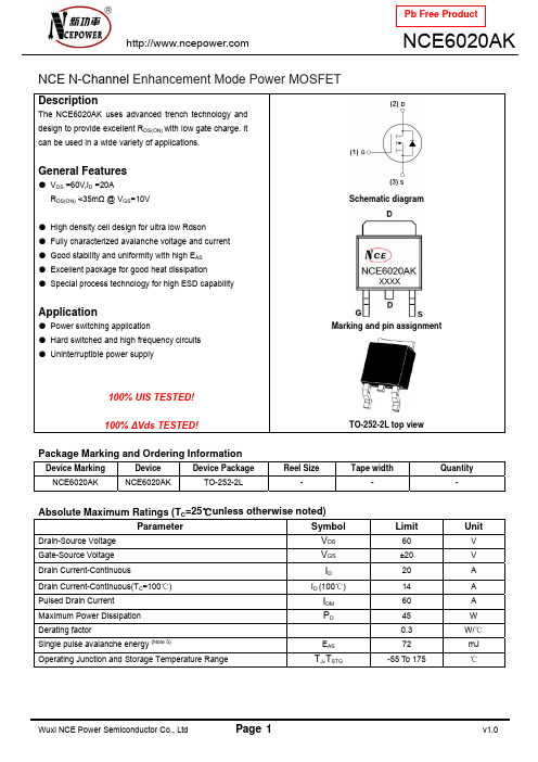
NCE N-Channel Enhancement Mode Power MOSFETDescriptionThe NCE6020AK uses advanced trench technology and design to provide excellent R DS(ON) with low gate charge. It can be used in a wide variety of applications.General Features● V DS =60V,I D =20AR DS(ON) <35m Ω @ V GS =10V● High density cell design for ultra low Rdson ● Fully characterized avalanche voltage and current ● Good stability and uniformity with high E AS ● Excellent package for good heat dissipation ● Special process technology for high ESD capabilityApplication● Power switching application● Hard switched and high frequency circuits ● Uninterruptible power supply100% UIS TESTED!100% ∆Vds TESTED!Schematic diagramMarking and pin assignmentTO-252-2L top viewPackage Marking and Ordering InformationDevice MarkingDeviceDevice PackageReel SizeTape widthQuantityNCE6020AK NCE6020AK TO-252-2L---Absolute Maximum Ratings (T C =25℃unless otherwise noted)Parameter Symbol Limit UnitDrain-Source Voltage V DS 60 V Gate-Source Voltage V GS±20 V Drain Current-ContinuousI D 20 ADrain Current-Continuous(T C =100℃) I D (100℃) 14 A Pulsed Drain Current I DM 60 A Maximum Power Dissipation P D45 W Derating factor0.3 W/℃Single pulse avalanche energy (Note 5)E AS 72 mJOperating Junction and Storage Temperature RangeT J ,T STG-55 To 175℃Thermal CharacteristicThermal Resistance,Junction-to-Case (Note 2)R θJC3.3/W ℃Electrical Characteristics (T C =25℃unless otherwise noted)Parameter Symbol ConditionMin Typ Max UnitOff CharacteristicsDrain-Source Breakdown Voltage BV DSS V GS =0V I D =250μA 60 - - V Zero Gate Voltage Drain Current I DSS V DS =60V,V GS =0V -- 1 μA Gate-Body Leakage Current I GSS V GS =±20V,V DS =0V - - ±100 nA On Characteristics (Note 3) Gate Threshold VoltageV GS(th) V DS =V GS ,I D =250μA 1.2 1.6 2.5 V Drain-Source On-State Resistance R DS(ON) V GS =10V, I D =20A - 27 35 m ΩForward Transconductance g FSV DS =5V,I D =5A 11- - S Dynamic Characteristics (Note4) Input Capacitance C lss - 500 - PFOutput CapacitanceC oss - 60 - PFReverse Transfer Capacitance C rssV DS =30V,V GS =0V,F=1.0MHz- 25 - PF Switching Characteristics (Note 4) Turn-on Delay Time t d(on) - 5 - nSTurn-on Rise Time t r - 2.6 - nS Turn-Off Delay Time t d(off) - 16.1 - nSTurn-Off Fall Time t fV DD =30V,I D =2A,R L =6.7Ω V GS =10V,R G =3Ω - 2.3 -nSTotal Gate Charge Q g - 47 nCGate-Source Charge Q gs - 6 nCGate-Drain ChargeQ gd V DS =30V,I D =4.5A,V GS =10V- 14 nC Drain-Source Diode Characteristics Diode Forward Voltage (Note 3) V SDV GS =0V,I S =20A -1.2 V Diode Forward Current (Note 2)I S - - 20 A Reverse Recovery Time t rr - 35 - nS Reverse Recovery Charge Qrr TJ = 25°C, IF =20Adi/dt = 100A/μs (Note3)- 53 - nCForward Turn-On Timet onIntrinsic turn-on time is negligible (turn-on is dominated by LS+LD)Notes:1. Repetitive Rating: Pulse width limited by maximum junction temperature.2. Surface Mounted on FR4 Board, t ≤ 10 sec .3. Pulse Test: Pulse Width ≤ 300μs, Duty Cycle ≤ 2%.4. Guaranteed by design, not subject to production5. EAS condition:Tj=25,VDD=℃30V,VG=10V,L=0.5mH,Rg=25ΩTest Circuit1) E AS test Circuit2) Gate charge test Circuit3) Switch Time Test CircuitTypical Electrical and Thermal Characteristics (Curves)Vds Drain-Source Voltage (V)Figure 1 Output CharacteristicsVgs Gate-Source Voltage (V)Figure 2 Transfer CharacteristicsI D - Drain Current (A)Figure 3 Rdson- Drain CurrentT J -Junction Temperature(℃)Figure 4 Rdson-Junction TemperatureQg Gate Charge (nC)Figure 5 Gate ChargeVsd Source-Drain Voltage (V)Figure 6 Source- Drain Diode ForwardR d s o n O n -R e s i s t a n c e (m Ω)I D - D r a i n C u r r e n t (A )I D - D r a i n C u r r e n t (A )N o r m a l i z e d O n -R e s i s t a n c eV g s G a t e -S o u r c e V o l t a g e (V )I s - R e v e r s e D r a i n C u r r e n t (A )Vds Drain-Source Voltage (V)Figure 7 Capacitance vs VdsVds Drain-Source Voltage (V)Figure 8 Safe Operation AreaT J -Junction Temperature(℃)Figure 9 BV DSS vs Junction TemperatureT J -Junction Temperature(℃)Figure 10 V GS(th) vs Junction TemperatureI D - D r a i n C u r r e n t (A )C C a p a c i t a n c e (p F )Square Wave Pluse Duration (sec)Figure 11 Normalized Maximum Transient Thermal Impedancer (t ),N o r m a l i z e d E f f e c t i v e T r a n s i e n t T h e r m a l I m p e d a n c eTO-252 Package InformationDimensions In Millimeters Dimensions In Inches SymbolMin.Max.Min.Max.A 2.200 2.400 0.087 0.094A1 0.000 0.127 0.000 0.005b 0.660 0.860 0.026 0.034c 0.460 0.580 0.018 0.023D 6.500 6.700 0.256 0.264D1 5.100 5.460 0.201 0.215 D2 0.483 TYP. 0.190 TYP.E 6.000 6.200 0.236 0.244e 2.186 2.386 0.086 0.0940.386 0.409L 9.80010.400L1 2.900 TYP. 0.114 TYP.L2 1.400 1.700 0.055 0.067 L3 1.600 TYP. 0.063 TYP.L4 0.600 1.000 0.024 0.039 Φ 1.100 1.300 0.043 0.051 θ0°8°0°8°h 0.000 0.300 0.000 0.012V 5.350 TYP. 0.211 TYP.Attention:■Any and all NCE power products described or contained herein do not have specifications that can handle applications that require extremely high levels of reliability, such as life-support systems, aircraft's control systems, or other applications whose failure can be reasonably expected to result in serious physical and/or material damage. Consult with your NCE power representative nearest you before using any NCE power products described or contained herein in such applications.■ NCE power assumes no responsibility for equipment failures that result from using products at values that exceed, even momentarily, rated values (such as maximum ratings, operating condition ranges, or other parameters) listed in products specifications of any and all NCE power products described or contained herein.■Specifications of any and all NCE power products described or contained herein stipulate the performance, characteristics, and functions of the described products in the independent state, and are not guarantees of the performance, characteristics, and functions of the described products as mounted in the customer’s products or equipment. To verify symptoms and states that cannot be evaluated in an independent device, the customer should always evaluate and test devices mounted in the customer’s products or equipment.■ NCE power Semiconductor CO.,LTD. strives to supply high-quality high-reliability products. However, any and all semiconductor products fail with some probability. It is possible that these probabilistic failures could give rise to accidents or events that could endanger human lives, that could give rise to smoke or fire, or that could cause damage to other property. When designing equipment, adopt safety measures so that these kinds of accidents or events cannot occur. Such measures include but are not limited to protective circuits and error prevention circuits for safe design, redundant design, and structural design.■ In the event that any or all NCE power products(including technical data, services) described or contained herein are controlled under any of applicable local export control laws and regulations, such products must not be exported without obtaining the export license from the authorities concerned in accordance with the above law.■No part of this publication may be reproduced or transmitted in any form or by any means, electronic or mechanical, including photocopying and recording, or any information storage or retrieval system, or otherwise, without the prior written permission of NCE power Semiconductor CO.,LTD.■Information (including circuit diagrams and circuit parameters) herein is for example only ; it is not guaranteed for volume production. NCE power believes information herein is accurate and reliable, but no guarantees are made or implied regarding its use or any infringements of intellectual property rights or other rights of third parties.■ Any and all information described or contained herein are subject to change without notice due to product/technology improvement, etc. When designing equipment, refer to the "Delivery Specification" for the NCE power product that you intend to use.■This catalog provides information as of Sep.2010. Specifications and information herein are subject to change without notice.。
常州安柏 AT810数字电桥说明书
!$Instruments 常州安柏精密仪器有限公司 江苏省常州市天宁区荡南工业园 [213014]电话:400 600 1217*************/89966117/89966227 销售服务电子邮件: *****************技术支持电子邮件: ****************©2005-2010 Applent Instruments, Inc.Rev.E固件说明:适用于主程序RevE0及以上的版本。
[AT810 LCR 数字电桥 ] 用户手册AT810 用户手册2安全须知当你发现有以下不正常情形发生,请立即终止操作并断开电源线。
立刻与安柏科技销售部联系维修。
否则将会引起火灾或对操作者有潜在的触电危险。
●仪器操作异常。
●操作中仪器产生反常噪音、异味、烟或闪光。
●操作过程中,仪器产生高温或电击。
●电源线、电源开关或电源插座损坏。
●杂质或液体流入仪器。
安全信息为避免可能的电击和人身安全,请遵循以下指南进行操作。
免责声明用户在开始使用仪器前请仔细阅读以下安全信息,对于用户由于未遵守下列条款而造成的人身安全和财产损失,安柏科技将不承担任何责任。
仪器接地 为防止电击危险,请连接好电源地线。
不可在爆炸性气体环境使用仪器 不可在易燃易爆气体、蒸汽或多灰尘的环境下使用仪器。
在此类环境使用任何电子设备,都是对人身安全的冒险。
不可打开仪器外壳 非专业维护人员不可打开仪器外壳,以试图维修仪器。
仪器在关机后一段时间内仍存在未释放干净的电荷,这可能对人身造成电击危险。
不要使用已经损坏的仪器 如果仪器已经损害,其危险将不可预知。
请断开电源线,不可再使用,也不要试图自行维修。
不要使用工作异常的仪器 如果仪器工作不正常,其危险不可预知,请断开电源线,不可再使用,也不要试图自行维修。
不要超出本说明书指定的方式使用仪器超出范围,仪器所提供的保护措施将失效。
声明:!, $, #,安柏标志和文字是常州安柏精密仪器有限公司的商标或注册商标。
德国百灵达产品参数

小型调音台UFX1604∙16通道模拟调音台,内置24/96火线音频接口∙8个XENYX话放,都带独立幻相供电开关∙16进4出火线音频接口∙支持MIDI走带控制的按钮,带背光∙100mm推子∙英式4段EQ,2个半参量EQ∙4个辅助发送/立体声返回,ALT 3-4总线,内置对讲话筒∙双通道多效果处理器∙可上机架QX-1202USB超低噪音(ULN) 电路,极大的动态余量,通透的音色8 个新颖的,录音棚级的―无形‖麦克风前置放大器:- 24 比特130 分贝动态范围,192 千赫采样率输入端-超大60 分贝增益范围内置24 比特数码立体声效果处理器,配有100 个音质优美的预置,如:混响,合唱,镶边,延迟,音高变动和各种多重效果所有声道配带有效的,音乐性极强的 2 频段均衡器,还配有削波二极发光管4 个平衡式线路输入端,动态余量充裕专业级4580 运算放大器, 超低噪音,极低失真度-- 要比4560 运算放大器好的多每路配有2 个辅助传送,1 前置推杆,适合监听使用;1 个后置推杆,适合内置效果或外置传送使用CD/磁带输入端可设置在主混音或控制室/耳机输出端上独立的控制室,耳机及立体声CD/磁带输出端平衡式主混音输出端,配有镀金卡侬连接插口提供+48 伏幻像电源开关,可使用电容话筒经久耐用的60 毫米流线型推杆和密封控制旋钮内置开关式电源(100 - 240 V ),使用灵活,具有无噪声,瞬间反应好,电耗低的特性高质量的元件和极其牢固的结构,使产品经久耐用德国百灵达研制设计X2442USB24 输入4/2 母线调音台, 配有XENYX 话放& 压缩器,英式均衡器,24 比特多种效果处理器,USB/音频界面和energyXT2 百灵达版音乐制作软件优质模拟调音台,超低噪音,大余量10 个技术新颖的XENYX 话筒前置放大器,配有幻象电源,可与单独的高级前置放大器媲美8个录音室级压缩器,配有简单的“一个按钮”功能和控制显示,打造一流的人声和乐器声新古典"英国式" 3 频段均衡器,配有半参数型中频,打造温暖的音色录音室级别效果处理器,配有16 种可编辑的预置,其中包括混响,合唱,镶边,延迟,变调,多重效果,节拍功能,用户参数设置可储存内置的立体声USB/音频插口可用来直接连接电脑。
M16B开发板实验指导书v1.0

安全需知
为防止损坏您的 AVR 相关工具,避免您或他人受伤,在使用本开发套装前请仔细阅读下面 的安全需知,并妥善保管以便所有本产品设备的使用者都可随时参阅。
请遵守本节中所列举的用以下符号所标注的各项预防措施,否则可能对产品造成损害。
该标记表示警告,提醒您应该在使用本产品前阅读 这些信息,以防止可能发生的损害。
警告
请勿在易燃气体环境中使用电子设备,以避免发生爆炸或火灾。 请勿在潮湿的环境中使用电子设备,以避免设备损坏。 发生故障时立即拔下所有线缆。 当您发现产品冒烟或发生异味时,请立刻拔下所有与其连接的线缆,切断电源,以避 免燃烧。若在这种情况下还继续使用,可能会导致产品的进一步损坏,并使您受伤。 请与我们联系后,将产品寄回给我们维修。 请勿自行拆卸本产品 触动产品内部的零件可能会导致受伤。 遇到故障时,请及时联系我们。 自行拆卸可能会导致其他意外事故发生。 使用合适的电缆线 若要将线缆连接到本设备的插座上,请使用本产品提供的线缆,以保证产品的规格的 兼容性。 请勿在儿童伸手可及之处保管本产品 请特别注意防止婴幼儿玩耍或将产品的小部件放入口中。
M16B 开 发 板 实验指导书
V1.0 – 2008-10-29
本资料由北京百纳信达科技有限公司编写、版权所有 商标咨询 ATMEL 与 AVR 分别是 ATMEL CORPORATION 的注册商标和商标 百纳信达、、 分别是北京百纳信达科技有限公司的商标与域名
实验二 Mega16 IO 口作为输入使用 ................................................................................................... 3
【实验目的】 .............................................................................................................................................. 3 【实验设备】 .............................................................................................................................................. 3 【实验要求】 .............................................................................................................................................. 3 【实验原理】 .............................................................................................................................................. 3 【实验步骤】 .............................................................................................................................................. 4 【范例路径】 .............................................................................................................................................. 4 【思考练习】 .............................................................................................................................................. 5
PSL601(A)系列数字式线路保护装置技术说明书要点
PSL601(A)系列数字式线路保护装置技术说明书V3.1国电南京自动化股份有限公司 2003年3月*本说明书可能会被修改请注意最新版本资料本技术说明书适用于以下版本的保护程序PSL 601纵联保护版本 3.16PSL 600后备保护版本 3.16PSL 600综合重合闸版本3.16装置修改说明1. PSL 601高频保护增加通道时间确认控制字可选择为5ms或8ms2. 距离和零序保护增加一个控制字KG3,其中1、增加快速距离投退控制位,2、零序段在非全相运行时是否加速控制位,零序段时间定值减去0.5s,3、零序段在是否增加一个辅助段,其电流定值和段相同无方向延时比段时间长1s3. 非全相永跳投入或退出控制字改为非全相再故障永跳或三跳4. CT反序修改为只在装置上电2小时之内检查5. 增加发停讯控制接点供录波使用6. 电流定值的最小值由0.1A改为0.05A7. 零序保护零序段和段的处理控制字选择为不灵敏段只在非全相运行及合闸100ms内投入选择为灵敏段则只在全相运行时投入合闸时延时100ms后才启动灵敏段的判断8. 零序保护增加3U0突变量开放零序保护控制字突变量取60ms前的保证3I0启动而不是突变量启动时也能判出3U0突变9. 闭锁式自动通道试验开始试验30秒后自动复归收发讯机复归信号持续1秒10. PSL 600零序功率方向元件电压浮动门坎该浮动门坎改动后限制其最大值为8V固定门坎为0.5V11.增加输出沟通三跳接点当重合闸退出三重方式充电未满或装置失电时沟通三跳接点闭合正常运行时打开沟通三跳接点12.增加合后继开入量输入解决先给保护电源再给操作电源时位置启动重合时可能动作的问题现在位置启动重合逻辑如下当控制字整定为合后继可用时位置启动重合除满足常规条件外还需合后继动作13.AD转换硬件改为AD加DSP模件目次1 概述 (1)1.1 保护配置及型号 (1)1.2 性能特征 (1)2 技术参数 (3)2.1 额定电气参数 (3)2.2 主要技术性能 (4)2.3 绝缘性能 (5)2.4 电磁兼容性能 (5)2.5 机械性能 (6)2.6工作大气条件 (6)3 保护原理说明 (7)3.1保护程序整体结构 (7)3.2启动元件和整组复归 (7)3.3 选相元件 (9)3.4 振荡闭锁的开放元件 (10)3.5 纵联保护 (12)3.6 波形比较法快速距离保护 (24)3.7距离保护 (25)3.8 零序电流保护 (30)3.9 非全相运行 (32)3.10 合闸于故障线路保护 (33)3.11 重合闸模件 (33)3.12 正常运行程序 (39)3.13 信息记录和分析 (40)3.14 与变电站自动化系统配合 (41)3.15 打印及显示信息一览表 (42)4 硬件使用说明 (45)4.1 PSL 601硬件使用说明 (45)4.2 PSL 601A硬件使用说明 (58)5 定值清单及整定说明 (65)5.1 PSL 601601A保护定值清单 (65)5.2 PSL 601601A保护定值整定说明 (68)5.3压板定值 (76)概述1 概述1.1 保护配置及型号PSL 601A型数字式超高压线路保护装置以纵联方向作为全线速动主保护以距离保护和零序方向电流保护作为后备保护保护有分相出口可用作220kV及以上电压等级的输电线路的主保护和后备保护保护功能由数字式中央处理器CPU模件完成其中一块CPU模件(CPU1) 完成纵联保护功能另外一块CPU模件(CPU2) 完成距离保护和零序电流保护功能对于单断路器接线的线路保护装置中还增加了实现重合闸功能的CPU模件(CPU3)可根据需要实现单相重合三相重合综合重合闸功能或者退出表1-1PSL 601A型数字式超高压线路保护的型号及其功能主要功能型号纵联保护距离保护和零序方向电流保护自动重合闸备注PSL 601能量积分方向,阻抗方向,零序方向快速距离保护三段式相间距离保护三段式接地距离保护四段式零序电流保护有适用于单断路器如双母线PSL 601A 同上同上无适用于23接线1.2 性能特征(1) 以能量积分方向为主以阻抗方向零序方向为辅的综合性方向元件作为纵联保护(2) 动作速度快线路近处故障动作时间小于10ms线路70处故障典型动作时间达到12ms线路远处故障小于25ms(3) 完善可靠的振荡闭锁功能能快速区分系统振荡与故障在振荡闭锁期间系统无论发生不对称性故障还是发生三相故障保护都能可靠快速地动作(4) 采用电流电压复合选相方法在复杂故障和弱电源系统故障时也能够正确选相(5) 纵联保护通道接口方式灵活可以与载波通道专用或复用光纤通道微波通道等各种通信设备连接有自适应判断弱电源侧的弱馈保护通道逻辑如通道检查位置停信等都由保护实现发停信控制采用单接点方式接点闭合为发信接点断开为停信(6) 完善的自动重合闸功能可以实现单重检线路三相有压重合闸方式专用于大电厂侧以防止线路发生永久故障电厂侧重合于故障对电厂机组造成冲击(7) 采用了多CPU共享AD的高精度模数转换自主专利技术解决了多CPU共享AD的难题提高了装置的模数转换精度简化了调试和维护的工作量(8) 通过了国家级电磁兼容实验室电磁辐射瞬变干扰等10个项目的抗干扰试验全部的试验结果证明其电磁兼容性能指标大大高于国家标准(9) 采用了全汉化显示/操作界面和全汉化图形化表格化打印输出(10) 采用透明化设计思想保护内部元件在系统故障时的动作过程可以全息再现便于分析保护的动作过程(11) 强大的故障录波功能可以保存1000次事件12至48次故障录波报告含内部元件动作过程故障时有重要开关量多次变化时会自动多次启动录波并且记录重要开关量如发信收信跳闸合闸等的变化录波数据可以保存为COMTRADE格式(12) 灵活的通信接口方式配有RS-232485和以太网通信接口(13) 通讯归约支持IEC60870-5-103标准2技术参数2 技术参数2.1 额定电气参数2.1.1 额定直流电压220V或110V(订货请注明)允许工作范围801152.1.2 额定交流数据a) 相电压 3/100 (额定电压Un)b) 线路抽取电压 100 V 或 3/100V有重合闸时可用软硬件自适应c) 交流电流 5A或1A(订货请注明额定电流In)d) 额定频率 50Hz或60Hz(60Hz时订货请注明)e) 过载能力电流回路 2 倍额定电流连续工作10倍额定电流允许10秒40倍额定电流允许1秒电压回路1.2倍额定电压连续工作1.8倍额定电压允许10秒2.1.3 功率消耗a) 直流回路正常时<40W跳闸时<50Wb) 交流电压回路 <0.5VA/相c) 交流电流回路 IQD +1.25IT其中为a,b,c三种相别T为20msi| i(t)-2*i(t-T)+i(t-2T) |为相电流突变量ITmax( | I(tT)-2*I(t-2T)+I(t-3T)) | )为相电流不平衡量的最大值当任一相电流突变量连续三次大于启动门坎时保护启动(2) 零序电流辅助启动元件为了防止远距离故障或经大电阻故障时相电流突变量启动元件灵敏度不够而设置该元件在零序电流大于启动门坎并持续30ms后动作(3) 静稳破坏检测元件为了检测系统正常运行状态下发生静态稳定破坏而引起的系统振荡而设置该元件判据为 BC相间阻抗在具有全阻抗特性的阻抗辅助元件内持续30ms或者A相电流大于1.2倍In持续30ms并且U1Cos小于0.5倍的额定电压当该元件动时保护启动进入振荡闭锁逻辑当PT1断线或者振荡闭锁功能退出时该检测元件自动退出3.2.2 启动继电器的闭锁措施PSL 601A数字式高压线路保护CPU模件硬件完全相同其出口回路完全独立任意一块CPU模件故障均不影响其他CPU模件的正常动作当采用三块CPU模件时启动回路可以由CPU1CPU3中两个CPU启动才开放保护出口继电器的负电源即构成三取二方式由于每个CPU都有较完善的硬件工况的监视系统单个硬件器件故障不会引起保护误动因此启动回路也可以选用三取一方式当只有两个保护CPU模件时如PSL 601A型保护对应的启动回路为二取二方式和二取一方式两种方式可以通过装置母板上的跳线JP1进行选择出厂时设置为三取一方式跳线JP1接法如下图所示两个连接片分别接在1和24和5上时即连接片在水平位置都连在左边启动继电器为三取一方式图中标识了1/3两个连接片分别接在2和35和6上时即连接片在水平位置都连在右边启动继电器为三取二方式图中标识了2/3当不接连接片时为三取二方式PT为电压互感器TV8保护原理说明JP11/32/3123456图3.2.1 母板中跳线JP1引脚图16为增加的示意标号3.2.3 整组复归各保护模件启动后就发出禁止整组复归的信号如果本保护所有的启动元件和故障测量元件都返回并且持续5秒本保护模件就收回禁止整组复归信号保护收到任一个模件禁止整组复归的信号就保持原先的启动状态直到所有模件都收回禁止整组复归信号时才能整组复归这样就能保证所有模件均满足整组复归条件时装置才整组复归3.3 选相元件选相元件是区分故障性质和相别以满足保护分相跳闸的要求PSL 601数字式线路保护的主保护和后备保护采用相同原理的选相元件为了在特殊系统(例如弱电源)和转换性等复杂故障下能够正确选相并有足够的灵敏度采用电压电流复合突变量和复合序分量两种选相原理相结合的方法在故障刚开始时采用快速和高灵敏度的突变量选相方法以后采用稳态的序分量选相方法保证在转换性故障时能够正确选相两种选相元件的原理如下3.3.1 电压电流复合突变量选相元件令ZIU× = &&φφφφφφcabcab,,=φφ其中φφU& φφI& 为相间回路电压电流的突变量Z为阻抗系数其值根据距离保护或者纵联方向保护中的阻抗元件的整定值自动调整设max min分别为abbcca中的最大值和最小值选相方法如下(1) 当min<0.25max时判定为单相故障否则为多相故障(2) 单相故障时若bc=min判定为a相故障若ca=min判定为b相故障若ab=min判定为c相故障(3) 多相故障时若同时满足ababU ≥ bcbcU ≥ 和cacaU ≥ 判定为区内相间故障否则为转换性故障(一正一反)采用相电流方向元件选择正向的故障相别9 保护原理说明(4) 判据 ()实际上是三个幅值比较方式的突变量方向继电器φφφφU≥ca bcab,,=φφ与传统的相电流差突变量选相原理相比本方法由于引进了电压突变量以及方向判别解决了弱电源系统和间隔时间很短的转换性故障的选相问题对于一般性的故障选相的灵敏度与相电流差突变量选相原理相当3.3.2 电压电流序分量选相元件令 ))31(arg(2200ZZIUIkUZ×××+=&&&&&θ即为补偿点零序电压和负序电压的相角差θ其中Z为阻抗系数与突变量选相元件类似ZK为零序补偿系数将的取值分成三个区θ每个区内包含有两种故障当时为A区oo9030≤< θ为A相接地或BC两相接地当90时为B区oo210≤<θ为B相接地或CA两相接地当时为C区oo330210≤Z时判定为A相接地否则(2) I或时105.0I<125.0IImI1时开放距离保护该方法是根据不对称故障时产生的零序和负序分量来开放保护m为可靠系数以确保区外故障时保护不会误动3) 振荡轨迹半径检测法系统纯振荡或振荡时发生经过渡电阻的故障测量阻抗的变化轨迹为园金属性故障时轨迹园蜕变为点阻抗变化率dz/dt与轨迹园的半径有内在的关系本方法是通过阻抗轨迹的测量来躲过会引起保护误动的振荡以及区外故障具体方法为在满足以下条件时开放BC相间距离11保护原理说明a) ∑c)dtdZZZbczdbc4 tSPm故 0)(tSm而此时对于线路端(属于正方向故障),同样存在能量函数n)(tSn并且有)()(tStSPnn =故 0)(即反向能量要大于正向能量综上所述能量函数有如下性质)(tSm()><=反向故障正向故障无故障tSm能量方向元件是根据故障附加网络的能量来判别故障方向从理论上解决了传统的故障分量超高速保护不能长期保持正确方向的缺点保护的动作快速性与安全性之间的矛盾得到了完美解决13保护原理说明在上面的理论推导中只是要求系统满足叠加原理而对于系统电源和其它各元件的特性没有作任何限制因此采用故障能量函数实现方向继电器时具有以下的优越特性能量函数不受故障暂态过程的影响因此不需要滤波换句话说故障电流电压中的工频分量非周期分量以及谐波分量都是能量函数在判别故障方向时有用的信息这就为实现超高速方向继电器打下了坚实的理论基础从故障一开始能量函数就有明确的方向性并且在故障持续期间其方向性不会任何改变,因此具有非常高的安全性使保护的动作快速性与安全性之间的矛盾得到了完美解决对于一些特殊系统的故障如串补线路故障中性点经消弧线圈接地系统的接地故障充电长线路发生反向出口故障或故障切除等由于受电容的影响基于工频量的方向继电器难以判别故障方向但能量函数的方向性不受任何影响另外由于反向故障时反向侧能量大于正向侧的能量在构成纵联方向保护时线路两侧的灵敏度自然得到配合能量函数在故障后一直保持明确的方向性但其大小一般是按两倍额定频率周期性波动的在电流过零时数值比较小保护的灵敏度和信噪比都下降为此可以将能量函数进一步积分构成能量积分函数即∫∫ =ttidtdtutSS00)(反向故障时由于能量函数始终大于0)(tS因此将S(t)积分后越积越大也就是说能量积分函数在反向故障时是单调上升的同理在正向故障时是单调下降的(绝对值则单调上升)因此不存在能量函数灵敏度下降的问题显然能量函数的其它优点能量积分函数仍然具备将数字化)(tSS可得能量积分函数的算法为[]∑∑ + + =jjababcacabcbckikukikukikuNTjSS0022)()()()()()()([]))1(,......,)1(,)0(max)( =jSSSSSSjM其中是三个相间回路故障电压和电流的突变量cabcabiu,,,,= φφφφφN为每周采样点数T为额定周期设故障开始的时间为0j就是故障开始后的采样点数也可以理解为故障已持续的时间14保护原理说明SS(j)称为能量积分函数是测量点检测到的故障能量的累计值M(j)是从故障开始到前一个采样点(j-1)之间能量积分函数的最大值能量积分函数SS(j)具有方向性正向故障时SS(j)0并且SS(j)还具有以下几个优越的特性1SS(j)的方向性不受故障暂态过程的影响故障工频分量非周期分量以及谐波分量对于SS(j)都是有用的信息因此不需要滤波可以实现超高速的方向继电器2故障期间SS(j)的方向性是始终正确的并且随着积分时间j的增加SS(j)的绝对值也单调的上升因此有|SS(j)|>M(j)基于能量积分函数的方向继电器的逻辑示意图如图3-5-3所示继电器由正向电压电流启动元件反向启动电压电流元件方向元件(SS(j)M(j))正向计时元件和反向计时元件等组成有正反两个方向的输出结果&Y2t+&Y1I>IQD+U>UQD+I>IQD-U>UQD-&JZ1SS(t)M(t-T)&JZ3&JZ21H11H2正向判定(SS)反向判定(SS)图3-5-3 能量积分方向继电器的逻辑示意图反向电流启动元件与装置的相电流差突变量启动元件相同采用固定门坎和浮动门坎相结合正向启动电流元件与反向类似只是将电流固定门坎抬高1.25倍使反向启动元件的灵敏度高于正向电压启动元件同样如此以正方向的判别为例:当SS(j)<0并正向电压电流启动元件动作时,通过正向计时计时达到积分时间门坎后输出正方向故障的判定结果正向元件动作后由H1将方向固定并闭锁反向元件的输出防止继电器由两个输出结果同样若反向元件先动作也将正方向元件闭锁正向计时元件还要受噪声检测元件的控制噪声检测元件的判据为|SS(j)|<M(J) 该元件动作时能量积分函数的单调性被破坏说明测量信号的噪声比较大计时器停止计15保护原理说明时但不返回待单调性恢复后再重新计数以进一步提高继电器的安全性积分时间决定了方向继电器的动作速度积分时间的长短不会影响方向判别的正确性但采取一定的积分时间可以提高方向判别的冗余度采用允许式时积分时间取2ms采用专用闭锁式时由于要有5ms的收信确认时间积分时间取5ms在不影响保护整组动作时间的前提下尽量多的利用故障信息由于能量方向元件的灵敏度很高为了减少通道干扰引起保护的误动在方向保护经通道逻辑配合判定为区内故障时由阻抗方向元件进行出口把关若在阻抗元件外保护延时30毫秒出口在此期间一旦检测到远方有闭锁信号对于允许方式则为允许信号消失则保护返回这样可以减小由于开关操作等因素产生通道干扰引起的误动对于一般性的故障阻抗出口把关不会影响保护的动作速度3.5.2 阻抗方向元件ZDRZDRZDZZDZZD图3-5-4 阻抗方向元件阻抗方向元件由高频距离阻抗定值ZZD和高频距离电阻定值RZD形成的两段圆弧组成动作判据为ρ<+ρRZD时ZD2ZD2ZDR2RZ+=ρ)90(jZD0ZDOe)R(Z + ρ=对于短线ZZD I-0ZDI+0ZD=纵联零序电流定值I-0ZD=零序电流启动定值零序方向元件的电压门坎取为固定门槛加浮动门槛动作范围oo32533arg1750≤≤IU3.5.4 方向元件配置PSL 601的能量方向阻抗方向和零序方向以反方向元件优先其中零序方向元件在合闸加速脉冲期间延时100毫秒动作在非全相运行时退出图3-5-5为方向元件配置70801H1T3FFI0I0ZZT2301H21H3&JZ1&JZ21H6&JZ31H4&JZ4&JZ51H7&JZ5FFT1图3-5-5 PSL 601(A)方向元件配置17保护原理说明3.5.5 通道方式纵联保护可以与载波通道专用或复用光纤通道微波通道等各种通信设备连接包括各种继电保护专用收发信机和复用载波机接口设备发停信控制采用一副接点不发信即为停信当用于专用闭锁式时通道逻辑完全由保护实现收发信机的停信和发信完全由保护控制为了防止通道上的干扰保护中设置了信号确认时间分为两级延时一是保护必须在收到闭锁信号5ms后才允许停信二是保护停信后要连续5ms或8ms通过控制字可选择建议光纤通道为5ms载波通道为8ms收不到闭锁信号才动作出口当用于允许式时采用单个允许信号为了防止区外故障切除时功率倒向引起保护的误动在反向元件动作10ms后投入功率倒向延时回路在反向转正向故障时近故障侧纵联保护延时40ms停信允许式为发信此时远故障侧纵联保护按常规逻辑执行这种功率倒向判断方法的优点是在非全相运行扰动导致启动等没有功率倒向的情况下发生线路故障时不会增加纵联保护的动作延时保护启动期间在检测到有其他保护动作开入量时一直停信允许式为发信在检测到断路器处于三跳位置后投入三跳位置停信回路以保证充电线路故障时充电侧纵联保护能够动作为了防止线路合闸时合闸环流引起保护的误动一旦检测到有三相合闸闭锁三跳位置停信功能150ms三跳位置停信分两种情况保护启动期间一直停信正常运行期间在收到闭锁信号后继续停信160ms以后就收回停信信号这样既能保证故障时对侧保护能够动作又不影响通道的检测通道检测的逻辑按四统一的方案可以手动检测也可通过控制字投入定时自动检测当用于允许式时由于本线路故障会引起通道的阻塞而导致保护拒动本保护还具有解除闭锁方式本保护不考虑单相故障造成通道阻塞的可能解除闭锁式只用于相间故障并且经控制字选择是否投入解除闭锁方式当本侧为正方向并且为相间故障时如果启动前无导频消失信号启动后的100ms内收到导频消失信号且无允许信号时保护跳闸动作3.5.6 弱馈保护弱馈保护作为线路弱馈端或无电源端的纵联保护使纵联保护达到全线速动的目的弱馈保护的功能当发生区内故障时弱馈侧能够快速发出允许对侧动作的信号并且18保护原理说明保持120 ms使对侧保护快速跳闸也就是说当用于专用闭锁式时弱馈侧能够快速停信用于允许式时弱馈侧能够快速发出允许信号当发生弱馈侧反方向故障时弱馈侧能够快速发出闭锁对侧动作的信号使纵联保护不误动弱馈侧的范围定义定性的说是线路弱馈端或者无电源端定量的说是当发生区内故障时某一端纵联保护的所有正方向元件灵敏度都不够时线路的该端可称为弱馈侧弱馈保护具有自适应于系统运行方式改变的能力即可能出现弱馈的一端可长期投入此功能该端变为强电侧时即使弱馈保护投入弱馈保护不会动作纵联保护仍然动作正确因为投入的弱馈保护是在正反方向元件都不动作时才可能发出允许对侧动作的信号特别要注意的是对于专用闭锁式的弱馈保护线路两端只能在其中的一侧投入弱馈功能否则在弱电源系统的强电源侧发生反向故障时如果线路两端的正反方向元件灵敏度不足时弱馈保护会误动所以对于专用闭锁式的弱馈保护弱馈保护在线路两端只能投入一侧对于弱馈侧当发生区内故障时用于专用闭锁式时弱馈侧可能无法停信导致对侧纵联保护拒动用于允许式时弱馈侧无法发出允许信号同样导致保护拒动下面以专用闭锁式为例本装置的弱馈保护具有下面两个功能(1) 当发生区内故障时弱馈侧快速停信(2) 弱馈侧可以选择跳闸弱馈侧能够启动满足下面条件时快速停信(1) 收到闭锁信号5ms(2) 正反方向元件均不动作表明非反方向故障(3) 至少有一相或者相间电压为低电压如果还满足下面两个条件弱馈侧跳闸(1) 弱馈侧跳闸控制字投入(2) 连续30ms收不到对侧的闭锁信号弱馈侧不启动满足下面条件时快速停信120ms(1) 收到闭锁信号10ms(2) 至少有一相或者相间电压为低电压3.5.6 纵联保护逻辑3.5.6.1高频专用收发信机闭锁式19保护原理说明20试验按钮1H1010&Y12000 0 2 & Y2 0 10" & Y3 1 H2 0 160 1 H3 T1 T2 T3 T4 T5 T6 & Y4 & Y6 1 H5& Y7 & Y8 & Y9 0 40 T7 & Y10 0 5 T9 50 10 T8H81H61H22&Y24&Y21&Y22120T115或8T10&Y23&Y251H2112010T12&Y26120T13&Y27&Y28030T141H19&Y11收信发信停信保护动作三跳位置定时检查通道保护起动整组复归保护跳闸信号反向元件动作低电压元件动作"1"1KG1.80"0"1H4120T211H30正向元件动作1KG1.110"0"1KG1.100"0"1H720T22KG1.8: 定时通道检查投入KG1.10:弱馈跳闸投入KG1.11:弱馈回音投入弱馈保护动作其他保护动作120T23PSL 601A纵联保护专用闭锁式逻辑保护原理说明高频专用收发讯机闭锁式逻辑1通道检查逻辑通道试验远方起信逻辑由本装置实现这样进行通道试验时就把两侧的保护装置收发信机通道一起进行检查与本装置配合时收发信机内部的远方起信逻辑部分应取消有手动通道检查开入或定时通道检查定时到时通过或门H1向对侧发送高频信号本侧收到这一高频信号经T2延时200ms闭锁与门Y1本侧不再发信同时与门Y1输出经时间元件T3展宽5s闭锁与门Y2因此本侧即使收到高频信号也要待T3返回后才能启动。
Futaba S3010 电控系列说明书
感谢您购买本产品!无刷动力系统功率强大,错误的使用可能造成人身伤害和设备损坏。
我们强烈建议您在使用设备前仔细阅读本说明书,并严格遵守规定的操作程序。
我们不承担因使用本产品而引起的任何责任,包括但不限于对附带损失或间接损失的赔偿责任;同时,我们不承担因擅自对产品进行修改所引起的任何责任。
我们有权在不经通知的情况下变更产品设计、外观、性能及使用要求。
· 电调与相关连接部件连接前,请确保所有电线和连接部件绝缘良好,短路会毁坏电调。
· 请务必仔细连接好各部件,若连接不良,您可能不能正常控制赛车,或出现设备损坏等其他不可预知的情况。
· 使用此电调前,请认真查看各动力设备以及车架说明书,确保动力搭配合理,避免因错误的动力搭配导致电机超载,最终损坏电调。
· 内置多种常用模式(如:零进角Zero Timing闪灯模式、一般练习模式、STOCK 竞赛模式),适合所有竞赛,即选即用。
电调的设定参数可以导入导出,便于车手相互交流和借鉴彼此的设定。
· 体积非常之小(31.6x25.8x16.2mm),车架布局更方便;重量非常之轻(不含线重量仅为23.5g),低重量为车架的平衡提供更多的可调空间。
· 内置BEC升压电路,BEC最大输出电流高达6A,且支持 6V和7.4V 切换,轻松驱动各种强力舵机及高压舵机。
03产品特色02注意事项05连接电子调速器06设置电子调速器设定油门行程1XERUN XR10 STOCK SPEC 1S车用无刷电子调速器使用说明书01声明1. 连接马达:连接有感无刷马达与无感无刷马达的方式有差异,请务必遵照如下接线方式: · 连接有感无刷马达时:电调与马达相连有严格的线序要求,电调的#A/#B/#C必须与电机的#A/#B/#C三线严格一一对应,用6针感应线把电调与电机的感应口对接。
若有感无刷马达未接上感应线,则电调会工作 在无感模式,相当于电调连接无感无刷电机。
RCLAMP0521P中文资料
Typical 9.3
Maximum 5 11
Units V V
0.025
1
µA
15
V
25
V
0.30
0.50
pF
2007 Semtech Corp.
2
元器件交易网
RClamp0521P
Clamping Voltage - VC (V)
PROTECTION PRODUCTS Typical Characteristics
Mechanical Characteristics
SLP1006P2 package Molding compound flammability rating: UL 94V-0 Marking: Marking code Packaging : Tape and Reel Lead Finish: NiPdAu RoHS/WEEE Compliant
90 80 70 60 50 40 30 20 10
0 0
Power Derating Curve
25
50
75
100
125
150
Ambient Temperature - TA (oC)
Clamping Voltage vs. Peak Pulse Current
24 22 20 18 16 14 12 10
10 MHz
100 MHz
13 GHz GHz
START. 030 MHz
STOP 3000.000000 MHz
3
元器件交易网
PROTECTION PRODUCTS Applications Information
Vista-20P中文说明书
柯德P4010ACS 120V AC电源火警报说明书
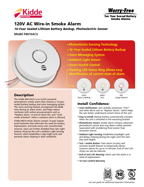
120V AC Wire-in Smoke Alarm10-Year Sealed Lithium Battery Backup, Photoelectric Sensor Model P4010ACSDescriptionThe Kidde P4010ACS is an AC/DC powered,photoelectric smoke alarm that contains a 10-year, sealed battery backup and voice messaging system. The voice warning feature accompanies the 85dB tone during an alarm event, and helps reduceInstall Confidence:• Voice Notification: Unit verbally announces “Fire!”and other alerts such as “Replace Alarm,” which helpsthe user better understand current status of the unit.• Easy to Install: Backup battery automatically activates Photoelectric Sensing Technology10 -Year Sealed Lithium Battery Backup Voice Messaging SystemAmbient Light SensorSmart Hush® ControlFlashing LED Status Ring allows easy identification of current state of alarmSee user guide for additional important information.Green:Device is WorkingAmber:ErrorRed:Danger DetectedArchitectural and Engineering SpecificationsThe smoke alarm model shall be P4010ACS or approved equal and is powered by a 120VAC, 60Hz source along with lithium battery backup. The lithium batteries shall be sealed in the 120V AC Wire-In Smoke Alarm10-Year Sealed Lithium Battery Backup, Photoelectric SensorModel P4010ACSInstallation of Smoke AlarmThe smoke alarm should be installed to comply with all local codes having jurisdic-tion in your area, Article 760 of the National Electric Code, and NFPA 72. Make certain all alarms are wired to a single, continuous (non-switched) power line, which is not protected by a ground fault interrupter. A maximum of 1000 ft. of wire can be 1016 Corporate Park Drive Mebane, NC Distributed by:P/N: KL-P4010ACS-sheet rev. 11-2017Ordering InformationOrdering Pack PackDimensionsCartons/NumberUPCI2F5Config.Quantity(w x d x h inches)WeightPallet21027537 0-47871-27537-3 100-47871-27537-0 Single 4 6.0 x 11.0 x 7.0 5 576Not for sale by individual uniting fires) sooner than ionization alams. Ionization alarms may detect invisible fire particles (associated with fast flaming fires) sooner than photoelectric alarms. Leading authorities recommend that both ionization and photoelectric smoke alarms be installed to help ensure maxi-mum detection of the various types of fires than can occur within the home.。
电脑的AT电源输出电压对照表
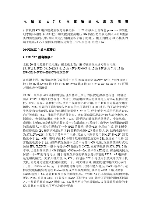
电脑的A T X电源输出电压对照表计算机的ATX电源脱离主板是需要短接一下20芯接头上的绿色poweron和黑色地才能启动的;启动后把万用表拨到主流电压20V档位,把黑表笔插入4芯D型插头的黑色接线孔中,用红表笔分别测量各个端子的电压;楼上列的是20芯接头的端子电压,4芯D型插头的电压是黄色+12V,黑色地,红色+5V;20-PINATX主板电源接口4-PIN“D”型电源接口主板20针电源插口及电压:在主板上看:编号输出电压编号输出电压13.3V113.3V23.3V12-12V3地13地45V14PS-ON5地15地65V16地7地17地8PW+OK18-5V95V-SB195V1012V205V在电源上看:编号输出电压编号输出电压205V1012V195V95V-SB18-5V8PW+OK17地7地16地65V15地5地14PS-ON45V13地3地12-12V23.3V113.3V13.3V可用万用电表分别测量;+3.3V:最早在ATX结构中提出,现在基本上所有的新款电源都设有这一路输出;而在AT/PSII电源上没有这一路输出;以前电源供应的最低电压为+5V,提供给主板、CPU、内存、各种板卡等,从第二代奔腾芯片开始,由于CPU的运算速度越来越快,INTEL公司为了降低能耗,把CPU的电压降到了3.3V以下,为了减少主板产生热量和节省能源,现在的电源直接提供3.3V电压,经主板变换后用于驱动CPU、内存等电路;+5V:目前用于驱动除磁盘、光盘驱动器马达以外的大部分电路,包括磁盘、光盘驱动器的控制电路;+12V:用于驱动磁盘驱动器马达、冷却风扇,或通过主板的总线槽来驱动其它板卡;在最新的P4系统中,由于P4处理器能能源的需求很大,电源专门增加了一个4PIN的插头,提供+12V电压给主板,经主板变换后提供给CPU和其它电路;所以P4结构的电源+12V输出较大,P4结构电源也称为ATX12V;-12V:主要用于某些串口电路,其放大电路需要用到+12V和-12V,通常输出小于1A.;-5V:在较早的PC中用于软驱控制器及某些ISA总线板卡电路,通常输出电流小于1A.;在许多新系统中已经不再使用-5V电压,现在的某些形式电源如SFX,FLEXATX一般不再提供-5V输出;在INTEL发布的最新的ATX12V1.3版本中,已经明确取消了-5V的输出;+5VStand—By,最早在ATX提出,在系统关闭后,保留一个+5V的等待电压,用于电源及系统的唤醒服务;以前的PSII、AT电源都是采用机械式开关来开机关机,从ATX开始包括SFX不再使用机械式开关来开机关机,而是通过键盘或按钮给主板一个开机关机信号,由主板通知电源关闭或打开;由于+5VStand-by是一个单独的电源电路,只要有输入电压,+5VSB就存在,这样就使电脑能实现远程Modem唤醒或网络唤醒功能;最早的ATX1.0版只要求+5VSB达到0.1A,随着CPU及主板的功能提高,+5VSB0.1A已不能满足系统的要求,所以INTEL公司在ATX2.01版提出+5VSB不低于0.72A;随着互联网应用的不断深入,一些系统要求+5VSB提供2A、3A,甚至更大的电流输出,以保障系统功能的实现,因此对电源提出了更高的设计要求;电脑电源上的输出线共有九种颜色,其中在主板20针插头上的绿色POWER-ON和灰色线POWER-GOOD,是主板启动的信号线,而黑色线则是地线G,其他的各种颜色的输出线的含义如下:红色线:+5VDC输出,用于驱动除磁盘、光盘驱动器马达以外的大部分电路,包括磁盘、光盘驱动器的控制电路,在传统上CPU、内存、板卡的供电也都由+5VDC供给,但进入PII时代后,这些设备的供电需求越来越大,导致+5VDC电流过大,所以新的电源标准将其部分功能转移到其他输出上,在最新的IntelATX12V2.2版本加强了+5V的供电能力,加强双核CPU的供电;它的电源质量的好坏,直接关系着计算机的系统稳定性;黄色线:+12VDC输出,用于驱动磁盘驱动器马达、冷却风扇,或通过主板的总线槽来驱动其它板卡;在最新的P4系统中,由于P4处理器能源的需求很大,电源专门增加了一个4PIN的插头,提供+12V电压给主板,经主板变换后提供给CPU 和其它电路而不再使用+5VDC,所以P4结构的电源+12V输出较大;如果+12V的电压输出不正常时,常会造成硬盘、光驱、软驱的读盘性能不稳定;当电压偏低时,表现为光驱挑盘严重,硬盘的逻辑坏道增加,经常出现坏道,系统容易死机,无法正常使用;偏高时,光驱的转速过高,容易出现失控现象,较易出现炸盘现象,硬盘表现为失速,飞转;随着加入了CPU和PCI-E显卡供电成分,+12V的作用在电源里举足轻重;目前,如果+12V供电短缺直接会影响PCI-E显卡性能,并且影响到CPU,直接造成死机;橙色线:+3.3VDC输出,是ATX电源设置为内存提供的电源;以前AT电源供应的最低电压为+5V,提供给主板、CPU、内存、各种板卡等,从PII时代开始,INTEL 公司为了降低能耗,把CPU、内存等的电压降到了3.3V以下;在新的24pin主接口电源中,着重加强了+3.3V供电;该电压要求严格,输出稳定,纹波系数要小,输出电流大,要20安培以上;一些中高档次的主板为了安全都采用大功率场管控制内存的电源供应,不过也会因为内存插反而把这个管子烧毁;使用+2.5VDDR内存和+1.8VDDR2内存的平台,主板上都安装了电压变换电路;白色线:-5VDC输出,5V是为逻辑电路提供判断电平的,需要的电流很小,一般不会影响系统正常工作,出现故障机率很小,在较早的PC中用于软驱控制器及某些ISA总线板卡电路.;在许多新系统中已经不再使用-5V电压,现在的某些形式电源一般不再提供-5V输出;-在INTEL发布的标准ATX12V1.3版本中,已经明确取消了-5V的输出,但大多数电源为了保持向上兼容,还是有这条输出线;蓝色线:-12VDC输出,是为串口提供逻辑判断电平,需要电流较小,一般在1安培以下,即使电压偏差较大,也不会造成故障,因为逻辑电平的0电平为-3到-15V,有很宽的范围;在目前的主板设计上也几乎已经不使用这个输出,而通过对+12VDC的转换获得需要的电流;紫色线:+5VStand—By,最早在ATX提出,通过PIN9向主板提供+5V720MA 的电源,在系统关闭后,保留一个+5V的等待电压,用于电源及系统的唤醒服务;这个电源为WOLWake-upOnLan和开机电路,USB接口等电路提供电源;如果你不使用网络唤醒等功能时,请将此类功能关闭,跳线去除,可以避免这些设备从+5VSB 供电端分取电流;这路输出的供电质量,直接影响到了电脑待机是的功耗,与我们的电费直接挂钩;绿色线:PS-ON电源开关端通过电平来控制电源的开启;当该端口的信号电平大于1.8V时,主电源为关;如果信号电平为低于1.8V时,主电源为开;使用万用表测试该脚的输出信号电平,一般为4V左右;因为该脚输出的电压为信号电平;这里介绍一个初步判断电源好坏的土办法:使用金属丝短接绿色端口和任意一条黑色端口,如果电源无反应,表示该电源损坏;现在的电源很多加入了保护电路,短接电源后判断没有额外负载,会自动关闭;因此大家需要仔细观察电源一瞬间的启动;灰色:PGPOWER-GOOD电源信号线一般情况下,灰色线PS的输出如果在2V以上,那么这个电源就可以正常使用;如果PS的输出在1V以下时,这个电源将不能保证系统的正常工作,必须被更换;这也是判断电源寿命及是否合格的主要手段之一;很明显,要考量一个电源的功率支持能力,最主要就是要看红色、黄色、橙色三条线的最大输出能力;。
- 1、下载文档前请自行甄别文档内容的完整性,平台不提供额外的编辑、内容补充、找答案等附加服务。
- 2、"仅部分预览"的文档,不可在线预览部分如存在完整性等问题,可反馈申请退款(可完整预览的文档不适用该条件!)。
- 3、如文档侵犯您的权益,请联系客服反馈,我们会尽快为您处理(人工客服工作时间:9:00-18:30)。
Return Loss dB min. VSWR max.
18
1.29
14
1.50
17
1.33
13
1.58
20
1.22
16
1.38
23
1.15
17
1.33
20
1.22
16
1.38
20
1.15
16
1.38
23
1.15
20.8
1.20
20.8
1.20
23
1.15
14
1.50
21
1.20
13
1.58
19
1.25
Load Life . . . . . . . . . . . . . .70؇C, 250 hours with rated load ∆A ) 0.5dB, ∆I ) 5%
Moisture and Load Life . . . . . . . . . . . . . 40؇C, 90-95%RH 90 minutes on, 30 minutes off, 0.2 watt, 120 cycles ∆A ) 0.5dB, ∆I ) 5%
元器件交易网
AT10 Series
Part Numbering System
AT 10 PK - 20dB 20S 500
Nominal Impedance Code: Expressed in ohms. A three digit code where the first two digits are significant figures, and the third digit indicates the number of zeros that follow these figures (i.e., 500 = 50Ω; 750 = 75Ω; 601 = 600Ω ).
Ⅲ 50Ω, 75Ω or 600Ω nominal impedance Ⅲ 6.5dB, 12dB or 20dB nominal attenuation Ⅲ 3-pin triangular PCB patterns Ⅲ Meets UL 94V-0 flammability requirements Ⅲ Sealed to withstand immersion cleaning
∆A = Attenuation Change at DC; ∆I = Impedance Change Ratio
102
TOCOS AMERICA, INC.
1177 East Tower Road, Schaumburg, IL 60173 Tel: 847-884-6664 Fax: 847-884-6665 E-mail: sales@
DC ~ 300MHz
DC ~ 500MHz
DC ~ 250MHz DC ~ 250MHz
DC ~ 250MHz
DC ~ 100kHz DC ~ 100kHz DC ~ 100kHz
Attenuation Flatness dB max. 0.2 0.3 0.2 0.3
A*= 0~10dB: 0.2 A*= 10~20dB: 2.0 A*= 0~10dB: 0.3 A*= 10~20dB: 4.5
20S
20mm
13mm
30S
30mm
23mm
Recommended PCB Layouts
P & PK Pin-Out
S Pin-Out
Unit: mm
Ø1.0 max. (3 holes)
IN
OUT
C
2.5ؓ0.3
2.5 2.5
ؓ0.3 ؓ0.3
5.0
ؓ0.6
C
Ø1.0 max. (3 holes)
Stop Strength . . . . . . . . . . . . . 800 gf • cm (11.09 oz • in) max.
Flammability of Plastic Materials . . . . . . . Meets UL 94V-0
Nominal Weight . . . . . . . . . . . . . . . . . . . . . 1.4g (P); 1.7g (S) 1.7g (PK 20mm shaft length) 2.0g (PK 30mm shaft length)
Shaft Length: 20S = 13mm Shaft with Knurled, Slotted End Style. 30S = 23mm Shaft with Knurled, Slotted End Style. Blank = No shaft.
元器件交易网
AT10 Series
TOCOS® AT T E N U AT O R S
10mm Square, Single-Turn, Through-Hole Sealed Cermet Attenuators
AT10P
AT10S
AT10PK
Features
Ⅲ 10mm square, single-turn, through-hole, sealed attenuators Ⅲ Cermet element Ⅲ Top and side adjust styles available Ⅲ Flush single-slot rotor adjustment Ⅲ Optional 20mm or 30mm plastic shaft with knurled, slotted end style
Specifications
Electrical Nominal Impedance . . . . . . . . . . . . . . . . . . 50Ω, 75Ω, 600Ω Attenuation Range at DC
Nominal Attenuation Attenuation Tolerance Minimum Attenuation
DC ~ 300MHz
DC ~ 500MHz
DC ~ 300MHz DC ~ 500MHz DC ~ 300MHz DC ~ 500MHz
DC ~ 300MHz
DC ~ 500MHz
DC ~ 100kHz DC ~ 100kHz DC ~ 100kHz DC ~ 300MHz DC ~ 500MHz DC ~ 300MHz DC ~ 500MHz
6.5dB 12dB
20dB
6.5dB 12dB
20dB
6.5dB 12dB 20dB 6.5dB 12dB
20dB
6.5dB 12dB 20dB 6.5dB 12dB 20dB
Frequency Range
DC ~ 300MHz DC ~ 500MHz DC ~ 300MHz DC ~ 500MHz
Unit: mm
AT10PK 13mm or 23mm Plastic Shaft with Knurled, Slotted End Style, Top Adjust, PK Terminal Style
AT10PK Shaft Codes and Dimensions
Shaft
L
A
Code ShaftHousing Length Actual Shaft Length
Vibration . . . . . . . . . . . . . . . . . .10-55Hz, 1.5mm amplitude, 3 directions, 2 hours each ∆A ) 0.5dB, ∆I ) 5%
Soldering Heat Resistance . . . . . . . . . . . 350؇C, 3 seconds ∆A ) 0.1dB, ∆I )1%
Thermal Shock . . . . . . . . . . . . . . . . . . . . . . 55؇C,100؇C, 30 minutes each, 5 cycles without load ∆A ) 0.5dB, ∆I ) 5%
Shock . . . . . . . . . . . . . 50G, 11ms, 6 directions, 3 times each ∆A ) 0.5dB, ∆I ) 5%
12
1.67
20
1.22
19
1.25
17
1.33
23
1.15
20.8
1.20
20.8
1.20
TOCOS AMERICA, INC.
103
1177 East Tower Road, Schaumburg, IL 60173 Tel: 847-884-6664 Fax: 847-884-6665 E-mail: sales@
5.0ؓ0.6
IN
OUT
2.5 2.5
ؓ0.3 ؓ0.3
5.0
ؓ0.6
Electrical Schematic
IN
R S1
RS2
ZIN RP
C
OUT ZO
104
TOCOS AMERICA, INC.
1177 East Tower Road, Schaumburg, IL 60173 Tel: 847-884-6664 Fax: 847-884-6665 E-mail: sales@
元器件交易网
AT10 Series
Model
Nominal Impedance
50Ω
AT10P & AT10PK
75Ω
600Ω0
50Ω AT10S
75Ω
600Ω0 * A = Attenuation
