DWR-131用户手册
AWAIS-1型船舶自动识别系统安装及使用说明书解读

第一部分:AWAIS-1操作说明书1 概述 (3)1.1 主要技术指标 (3)1.2 MKD显示器外形图 (3)2 安装要求 (3)2.1 安装位置 (3)2.2 注意事项 (3)3 MKD显示器功能介绍 (4)3.1 MKD前面板按键功能 (4)3.2 MKD显示器背面及接口介绍 (5)3.3 MKD液晶显示分区 (6)4 MKD显示器基本操作 (6)4.1 开机/关机 (6)4.2 功能菜单 (7)4.2.1 船只列表菜单 (8)4.2.2 本船参数设置菜单 (8)4.2.2.1 静态信息菜单 (9)4.2.2.1.1 船只静态信息菜单 (9)4.2.2.1.2 到达时间设置菜单 (10)4.2.2.1.3 频道设置菜单 (11)4.2.2.1.4 航行信息菜单 (12)4.2.2.1.5 GPS设置菜单 (14)4.2.2.2 远程设置菜单 (15)4.2.2.3 报警信息菜单 (16)4.2.2.3.1 继电器设置菜单 (16)4.2.2.3.2 状态信息菜单 (17)4.2.2.3.3 报警信息菜单 (18)4.2.2.3.4 停止运行信息菜单 (18)4.2.2.4 其他信息菜单 (19)4.2.2.4.1 密码设置菜单 (19)4.2.2.4.2 自检功能 (20)4.2.2.4.3 版本菜单 (21)4.2.2.4.4 波特率设置菜单 (22)4.2.2.5 区域设置菜单 (22)4.2.2.5.1 已设置区域菜单 (23)4.2.2.5.2 设置新区域菜单 (23)4.2.3 船只详细信息菜单 (25)4.2.4 短信息菜单 (26)4.2.4.1 已发短信息 (26)4.2.4.2 已收短信息 (27)4.2.4.3 发短信息 (28)4.2.4.4 远程信息菜单 (32)4.2.5 显示设置 (33)4.2.6 海图显示菜单 (33)4.2.7 本船信息菜单 (34)4.2.8 报警信息对话框 (35)5 维护 (35)第二部分:AWAIS-1安装说明书设备组成 (36)6 安装 (37)6.1 主机安装 (37)6.2 MKD安装 (37)6.3 VHF天线安装 (37)6.4 GPS天线安装 (37)6.5 接线盒安装 (38)7 接线 (40)7.1 电源线连接 (40)7.1.1 主机电源 (40)7.1.2 显示控制器电源 (40)7.2 数据线连接 (40)7.2.1 主机数据线连接方法 (40)7.2.2 显示控制器数据线 (40)7.3 接线盒连线说明 (41)8 指示灯 (43)9 设备安装尺寸 (44)9.1 主机 (44)9.2 显示控制器 (44)9.3 接线盒 (45)10 附录 (46)10.1 参考资料 (46)10.2 输入输出语句列表 (46)10.2.1 传感器输入语句 (46)10.2.2 AIS语句 (46)1 概述本设备(MKD)是上海埃威航空电子有限公司研制的自动识别系统(AIS)的显示控制器, 它采用RS422通信方式与系统主机(AIS)进行数据交换,获取本船及其他安装有AIS设备的船只的航行信息,有效提高航行效率,减少交通事故,保障航行中的财产和生命安全。
TI(德州仪器)公司产品导购手册

TI(德州仪器)德州仪器,简称TI,全球约 30,300人,总部位于美国得克萨斯州的达拉斯,2008年营业额为185亿美元, 是全球领先的半导体公司,为现实世界的信号处理提供创新的数字信号处理(DSP)及模拟技术, 应用领域涵盖无线通讯、宽带、网络家电、数字马达控制与消费类市场。
TI(德州仪器)目录更多关于产品•MSP430系列单片机•TMS370系列单片机•TMS470系列单片机•Stellaris系列单片机•32位C2000单片机•C2000 DSP•C5000 DSP•C6000 DSP•达芬奇 DSP•A/D转换器•D/A转换器•电池管理•PWM控制器•DC/DC控制器MSP430系列单片机MSP430 系列是一个 16 位的、具有精简指令集的、超低功耗的混合型单片机,在 1996 年问世,由于它具有极低的功耗、丰富的片内外设和方便灵活的开发手段,已成为众多单片机系列中一颗耀眼的新星。
MSP430 系列单片机的迅速发展和应用范围的不断扩大,主要取决于以下的特点。
强大的处理能力 MSP430 系列单片机是一个 16 位的单片机,采用了精简指令集( RISC )结构,具有丰富的寻址方式( 7 种源操作数寻址、 4 种目的操作数寻址)、简洁的 27 条内核指令以及大量的模拟指令;大量的寄存器以及片内数据存储器都可参加多种运算;还有高效的查表处理指令;有较高的处理速度,在 8MHz 晶体驱动下指令周期为 125 ns 。
这些特点保证了可编制出高效率的源程序。
在运算速度方面, MSP430 系列单片机能在 8MHz 晶体的驱动下,实现 125ns 的指令周期。
16 位的数据宽度、 125ns 的指令周期以及多功能的硬件乘法器(能实现乘加)相配合,能实现数字信号处理的某些算法(如 FFT 等)。
MSP430 系列单片机的中断源较多,并且可以任意嵌套,使用时灵活方便。
当系统处于省电的备用状态时,用中断请求将它唤醒只用 6us 。
IWCTT系列无线电流变比器传输器操作手册说明书

|IWCTT SeriesINDUSTRIAL WIRELESS CURRENT TRANSFORMER TRANSMITTERWhilst every effort has been taken to ensure the accuracy of this document, we accept no responsibility for damage, injury, loss, or expense resulting from errors or omissions, and reserve the right of amendment without notice.Information for usersThis equipment has been tested and found to comply with the limits for a Class B device, pursuant to part 15 of the FCC Rules. These limits are designed to provide reasonable protection against harmful interference in a residential installation. This equipment generates uses and can radiate radio frequency energy, and if not installed and used in accordance with the instructions, may cause harmful interference to radio communications. However, there is no guarantee that interference will not occur in a particular installation. If this equipment does cause harmful interference to radio or television reception, which can be determined by turning the equipment off and on, the user is encouraged to try to correct the interference by one or more of the following measures:•Reorient or relocate the receiving antenna•Increase the separation between the equipment and receiver•Connect the equipment into an outlet on a circuit different from that which the receiver is connected•Consult the dealer or an experienced radio/TV technician for helpCaution: To satisfy FCC RF Exposure requirements for mobile and base station transmission devices, a separation distance of 20cm or more should be maintained between the antenna of this device and persons during operation. To ensure compliance operation at closer than this distance is not recommended. The antenna used for this transmitter must not be co-located or operating in conjunction with any other antenna or transmitter. No other antenna may be used with this equipment other than the PCB antenna supplied with this equipment.This document may not be reproduced in any way without the prior written permission of the company.Cynergy3 Components Ltd7 Cobham Road, Ferndown Industrial Estate, WimborneDorset BH21 7PE, United KingdomTel:+44(0)1202897969,email:******************CONTENTS1.INTRODUCTION _______________________________________________________ 3 1.1 Safety Information________________________________________________________ 31.2Hardware Features_______________________________________________________ 32.UNPACKING__________________________________________________________ 43.PRODUCT IDENTIFICATION LABEL _____________________________________ 44.INSTALLING/CHANGING THE BATTERY________________________________ 45.SETTING UP THE IWT WIRELESS TRANSMITTER________________________ 56.TROUBLE-SHOOTING GUIDE__________________________________________ 77.SYSTEM PART NUMBERS______________________________________________ 88.SPECIFICATIONS______________________________________________________ 81. INTRODUCTION1.1 Safety InformationThis manual contains information that must be observed in the interest of your safety and to avoid damage to assets. Please read this manual before installing and commissioning the device and keep the manual in an accessible location for all users.Contains FCC ID: W70MRF24J40MDMECaution: To satisfy FCC RF Exposure requirements for mobile and base station transmission devices, a separation distance of 20cm or more should be maintained between the antenna of this device and persons during operation. To ensure compliance operation at closer than this distance is not recommended. The antenna used for this transmitter must not be co-located or operating in conjunction with any other antenna or transmitter. No other antenna may be used with this equipment other than the PCB antenna supplied with this equipment.Please see the Certifications section for more information on RF Exposure Compliance 1.2 Hardware FeaturesOur range of IWT wireless transmitters are available for a wide range of input types.The IWCTT Current Transformer Transmitter has been designed to accept an input from any mV AC output current transformer up to 500mVac and transmit the value to one of the IWR range of receivers.Please note that the IWCTT can also accept mV DC inputs up to a maximum of 0-500mVdcDepending on the receiver used, the value can be outputted as either a 4-20 mA or1-5 V dc signal, displayed and logged on a PC, output as a Modbus RTU or TCP/IP register, or transmitted to a remote server using MQTT messages. The range of receivers available is shown in the table below.Receiver Type FeaturesIWR-1 1 off 4-20 mA or 1-5 V and 1 off Relay OutputIWR-5 5 off 4-20 mA or 1-5 V and 1 off Relay OutputIWR-USB Connects to any PC for data display and loggingIWR-PORT Stores data from IWT transmitters as Modbus RegistersIoT-Gateway Stores data from IWT Transmitters & sends it to remoteservers using MQTT packetsThe IWCTT Current Transformer transmitter works within the ISM license-free 2.4GHz bands.Ranges of up to 500 m are possible using the standard transmitter and receiver unit with the optional 3dBi antenna giving a range of up to 750 m.The transmitter is powered by a primary 3.6 V lithium cell and care must be taken to insert the battery in the correct polarity.2.UNPACKINGThe instrument should be carefully inspected for signs of damage that may have occurred in transit. In the unlikely case that damage has been sustained, DO NOT use the instrument, but please retain all packaging for our inspection and contact your supplier immediately.3. PRODUCT IDENTIFICATION LABELThe unit delivered should be carefully inspected to ensure it is suitable for the application required. Detailed information on the product is included in the identification label and the user manual.Please ensure, in particular, that the input range of the IWT is suitable for the intended application and that the IWT unit will not be subjected to temperatures greater than those specified in this manual.4. INSTALLING/CHANGING THE BATTERYA Lithium 3.6V battery is included inside the IWT transmitter. The battery may be changed at any time, but care must be taken to install the battery with the correct polarity. After the battery has been changed, the unit should be switched on using the yellow slider switch SW3 and then the pushbutton SW1 should be pushed and held for 5s. This is to ensure the battery life count is reset correctly when a new battery is installed.The internal red LED will flash 5 times to indicate this procedure has been carried out successfully.The battery life is determined by the rate the transmitter sends the Temperature value to the receiver, this update rate can be selected using Dip Switch 1 and the default value is 10s.Please dispose of all batteries as specified by the legislator according to the Closed Substance Cycle and Waste Management Act or country regulations.! ! WARNING !MAKE SURE THE CORRECT BATTERY POLARITY IS OBSERVED!!! WARNING !INCORRECT BATTERIES MAY DAMAGE THE UNIT USE ONLY 3.6V LITHIUM C CELL BATTERIES5. SETTING UP THE IWT WIRELESS TRANSMITTERThe IWT instrument is shipped in a default configuration which allows the unit to connect with any default IWR receiver unit and transmit the measured signal every 10s simply by switching the unit on using SW3 on the internal circuit board.If a different update rate is required, or a different network frequency channel is required these parameters can be selected using DIP Switch 1 as detailed below:Switches 1, 2, 3 & 4 select the RF Network the IWT will transmit on. The default network for both the IWT transmitter and IWR receiver is network 1. RF NETWORK 1 2 3 4 1 0 0 0 0 2 0 0 0 1 3 0 0 1 0 4 0 0 1 1 5 0 1 0 0 6 0 1 0 1 7 0 1 1 0 8 0 1 1 19 1 0 0 010 1 0 0 1 11 1 0 1 0 12 1 0 1 1 13 1 1 0 0 14 1 1 0 1 15 1 1 1 0 16 1 1 1 1DIP SWITCHLED1BATTERYON/OFF Switch SW3SW1USB+Switches 5, 6 & 7 select the Transmission rate of the unit. This effectively sets how often the measured value is sent to the receiver.At 1 and 5 second rate, a power save option is available (on by default) that changes the transmit time to every 30 seconds if the IWR is switched off or out of range for more than 3 minutes. This option can be changed using the IWT-SET program.Transmit time 5 6 710 seconds 0 0 020 seconds 0 0 130 seconds 0 1 060 seconds 0 1 1120 seconds 1 0 0600 seconds 1 0 11 second 1 1 05 seconds 1 1 1Switches 8, 9, and 10 set the Channel Number of the transmitter. This is used with the 5 channel receiver unit (IWR-5) to select which IWT wireless transmitter is linked to which 4-20 mA or 1-5 V dc output channel.Channels 1 to 128 can be used with an IWR-USB, IWR-PORT, or IoT Gateway receiver. The channel number can be changed using the IWT-SET PC configuration software if switches 8, 9, and 10 are switched to the on position.Tx Channel Number 8 9 101 0 0 02 0 0 13 0 1 04 0 1 15 1 0 06 1 0 17 1 1 08 (or 1 to 128) 1 1 1The IWT transmitter is now set up and ready to be used. Install the unit where required, wire the appropriate input into the IWT as specified below (if there isn’t an integral sensor), and switch the unit ON using SW3. Pushbutton switch SW1 can be pushed to force the unit to transmit its current measured value. A red LED 1 will flash once when the transmit button is pressed and flash a second time if the transmission has been received and acknowledged by an IWR receiver unit.If the unit has transmitted successfully, the output of the connected receiver unit will output a value reflecting the signal level being measured.6.TROUBLE-SHOOTING GUIDEProblem encountered Possible CausesLED1 doesn’t flash when pushbutton SW1 is pressed Unit not switched on, switch on using SW3. The battery is not installed correctly.The battery needs replacing.LED1 only flashes once when SW1 is pressed IWR receiver not switched on. IWR receiver is not set up for the same RFnetwork.IWR receiver not within range of the transmitter.If an IWR-1 receiver is used, ensure that the transmitter is set to Tx Channel 1Output from the IWR receiver isn’t equivalent to the signal being monitored IWR receiver set up incorrectly, see IWR user manual for further details.Check that the green external LED on the receiver is flashing when the transmitter push button is pressed as the receiver may be out of range.7. SYSTEM PART NUMBERS8.SPECIFICATIONSPart Number Range Connection IWCTT50 0 - 50 mV ac 1. +ve 2. -ve IWCTT200 0 - 200 mV ac 1. +ve 2. -ve IWCTT330 0 - 330 mV ac 1. +ve 2. -ve IWCTT5000 - 500 mV ac1. +ve2. -veReceiver Part NumberNumber of Output ChannelsIWR-1 One IWR-5 FiveIWR-USB Data from up to 128 IWT Transmitters IWR-PORT Data from up to 128 IWT Transmitters IoT-Gateway Data from up to 128 IWT TransmittersIANT-33 dBi AntennaSystem PerformanceAccuracy (non-linearity & hysteresis) <± 1.0 % FSDSetting Errors Zero & Full Scale, <± 1.0% FSDInput rangeAc/dc mV From CT up to 0-500mV Ambient Temperature -20 to +80 °C Storage Temperature -20 to +80 °CWeight310 gRF TransmitterContains FCC W70MRF24J40MDME Power Requirements Lithium Thionyl Chloride C 3.6 V Cell Battery Life 5 Years (10s transmission rate)Dimensions 79 mm x 79 mm x 52mm (L x W x D)Mounting Any OrientationUnited States FCCThis equipment has been tested and found to comply with the limits for a Class B device, pursuant to part15 of the FCC Rules. These limits are designed to provide reasonable protection against harmful interference in a residential installation. This equipment generates, uses, and can radiate radio frequency energy, and if not installed and used in accordance with the instructions, may cause harmful interference to radio communications. However, there is no guarantee that interference will not occur in a particular installation. If this equipment does cause harmful interference to radio or television reception, which can be determined by turning the equipment off and on, the user is encouraged to try to correct theinterference by one or more of the following measures:•Reorient or relocate the receiving antenna•Increase the separation between the equipment and receiver•Connect the equipment into an outlet on a circuit different from that which the receiver is connected•Consult the dealer or an experienced radio/TV technician for helpWarning: Changes or modifications not expressly approved by Cynergy3 could void the user’s authority to operate the equipment.RF ExposureContains FCC ID: W70MRF24J40MDMEIn this equipment, the antenna supplied is a PCB antenna and an alternative antenna must not be used. Caution: To satisfy FCC RF Exposure requirements for mobile and base station transmission devices, a separation distance of 20cm or more should be maintained between the antenna of this device and persons during operation. To ensure compliance operation at closer than this distance is not recommended. The antenna used for this transmitter must not be co-located or operating in conjunction with any other antenna or transmitter. No other antenna may be used with this equipment other than the PCB antenna supplied with this equipment.Canada (IC)EnglishThis device complies with Industry Canada license-exempt RSS standard(s). Operation is subject to the following two conditions: (1) this device may not cause interference, and (2) this device must accept any interference, including interference that may cause undesired operation of the device.Under Industry Canada regulations, this radio transmitter may only operate using an antenna of the type and maximum (or lesser) gain approved for the transmitter by Industry Canada. To reduce potential radio interference to other users, the antenna type and its gain should be so chosen that the equivalent isotropically radiated power (e.i.r.p.) is not more than that necessary for successful communication. FrenchLe présent appareil est conforme aux CNR d’industrie Canada applicables aux appareils radio exempts de licence. L’explitation est autorisée aux deux conditions suivantes: (1) l’appareil ne doit pas produire de brouillage, et (2) l’utilisateur de l’appareil doit accepter tout brouillage, et (2) l’utilisateur de l’appareil doit accepter tout brouillage radioelectrique subi, même si le brouillage est susceptible d’en compromettre le fonctionnement.Conformément à la réglementation d’Industrie Canada, le présent émetteur radio peut fonctionner avec une antenna d’un type et d’un gain maximal (ou inférieur) approuvé pour l’émetteur par Industrie Canada. Dans le but de réduire les risques de brouillage radioélectrique à I’intention des autres utilisateurs, il faitchoisir le type d’antenne et son gain de sorte que la puissance isotrope rayonnée équivalente (p.i.r.e) ne dépasse pas l’intensité nécessaire à l’établissement d’une communication satisfaisante.| IWCTT SERIES WIRELESS CURRENT TRANSFORMER TRANSMITTER OPERATING MANUALC opyright © 2021 Sensata Technologies, Inc. Page 11 Sensata Technologies, Inc. (“Sensata”) data sheets are solely intended to assist designers (“Buyers”) who are developing systems thatincorporate Sensata products (also referred to herein as “components”). Buyer understands and agrees that Buyer remains responsible forusing its independent analysis, evaluation and judgment in designing Buyer’s systems and products. Sensata data sheets have been createdusing standard laboratory conditions and engineering practices. Sensata has not conducted any testing other than that specifically describedin the published documentation for a particular data sheet. Sensata may make corrections, enhancements, improvements and other changesto its data sheets or components without notice.Buyers are authorized to use Sensata data sheets with the Sensata component(s) identified in each particular data sheet. HOWEVER, NOOTHER LICENSE, EXPRESS OR IMPLIED, BY ESTOPPEL OR OTHERWISE TO ANY OTHER SENSATA INTELLECTUAL PROPERTY RIGHT, ANDNO LICENSE TO ANY THIRD PARTY TECHNOLOGY OR INTELLECTUAL PROPERTY RIGHT, IS GRANTED HEREIN. SENSATA DATA SHEETSARE PROVIDED “AS IS”. SENSATA MAKES NO WARRANTIES OR REPRESENTATIONS WITH REGARD TO THE DATA SHEETS OR USE OF THEDATA SHEETS, EXPRESS, IMPLIED OR STATUTORY, INCLUDING ACCURACY OR COMPLETENESS. SENSATA DISCLAIMS ANY WARRANTYOF TITLE AND ANY IMPLIED WARRANTIES OF MERCHANTABILITY, FITNESS FOR A PARTICULAR PURPOSE, QUIET ENJOYMENT, QUIETPOSSESSION, AND NON-INFRINGEMENT OF ANY THIRD PARTY INTELLECTUAL PROPERTY RIGHTS WITH REGARDTO SENSATA DATA SHEETS OR USE THEREOF.All products are sold subject to Sensata’s terms and conditions of sale supplied at SENSATA ASSUMES NO LIABILITYFOR APPLICATIONS ASSISTANCE OR THE DESIGN OF BUYERS’ PRODUCTS. BUYER ACKNOWLEDGES AND AGREES THAT IT IS SOLELYRESPONSIBLE FOR COMPLIANCE WITH ALL LEGAL, REGULATORY AND SAFETY-RELATED REQUIREMENTS CONCERNING ITS PRODUCTS,AND ANY USE OF SENSATA COMPONENTS IN ITS APPLICATIONS, NOTWITHSTANDING ANY APPLICATIONS-RELATED INFORMATION ORSUPPORT THAT MAY BE PROVIDED BY SENSATA. Mailing Address: Sensata Technologies, Inc., 529 Pleasant Street, Attleboro, MA 02703, USA.CONTACT US EUROPE +44 (0)1202 897969 ********************* Cynergy3 Components Ltd. 7 Cobham Road, Ferndown Industrial Estate, Wimborne, Dorset, BH21 7PE, United Kingdom USA +1 310 561 8092 / +1 866 258 5057 ********************* Europe The MRF24J40MD/ME wireless module used in this equipment has been tested and is in conformity with the essential requirements and other relevant requirements of the RED Directive 2014/53/EU. That module is in conformity with the following standards and/or other normative documents:Certification Standards Article Safety EN60950-1-2006 / A11:2009 / A1:2010 / A12:2011 / A2:2013(3.1(a)) Health EN 300 328 V2.1.1 / EN 62479:2010 (3.1(a)) EMC EN 301 489-1 V2.1.1 EN 301 489-1 V2.2.0 EN 301 489-17 V3.1.1 EN 301 489-17 V3.2.0(3.1(b)) Radio EN 300 328 V2.1.1 (3.2)。
Dwr入门操作手册
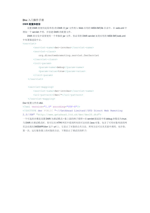
Dwr入门操作手册DWR配置和使用设置DWR的使用是简单的:将DWR的jar文件拷入Web应用的WEB-INF/lib目录中,在web.xml中增加一个servlet声明,并创建DWR的配置文件。
DWR的分发中需要使用一个单独的jar文件。
你必须将DWR servlet加到应用的WEB-INF/web.xml中布署描述段中去。
<servlet><servlet-name>dwr-invoker</servlet-name><servlet-class>org.directwebremoting.servlet.DwrServlet</servlet-class><init-param><param-name>debug</param-name><param-value>true</param-value></init-param></servlet><servlet-mapping><servlet-name>dwr-invoker</servlet-name><url-pattern>/dwr/*</url-pattern></servlet-mapping>Dwr配置文件的dtd:<?xml version="1.0" encoding="UTF-8"?><!DOCTYPE dwr PUBLIC "-//GetAhead Limited//DTD Direct Web Remoting2.0//EN" "/dwr/dwr20.dtd">一个可选的步骤是设置DWR为调试模式—象上面的例子那样—在servlet描述段中将debug参数设为true。
瓦尔特兵卒1控制阀使用指南说明书

Valtek Trooper1Valtek Trooper2The Valtek ® Trooper valve is a high-performance,general-service control valve with a high-thrust dia-phragm actuator. The valve is designed for use in ANSI Class 150 or 300 service applications with temperatures ranging from -20° to 650° F / -30° to 345° C.In addition to its high thrust, the reversible actuator is compact. An optional integral I/P or P/P positioner ensures high positioning accuracy proportional to the valve instrument signal. The integrally mounted posi-tioner eliminates external tubing requirements, reduces pinch points and keeps moving parts safe from external dirt and damage. Reversing the actuator does not require positioner, tubing changes or extras parts.The actuator accepts air supply pressures up to 60 psig / 4 Barg allowing the valve to shutoff against high-pressure drops. Different spring-sets are available to meet individual application requirements. Removing the reversible actuator from the valve is easy with the unique yoke design and yoke clamps.Many of the standard Mark One valve features are included in the Trooper general service valve including heavy duty, stem guides; self-centering, clamped-in seat ring; raised face integral flanges, multiple trim reductions and easy top-entry valve accessibility.The Trooper valve is available in 1, 11/2, 2, 3 and 4-inch valve sizes and with carbon steel or stainless steel bodies. Valve sizes 1 through 2-inch are also available in socketweld or NPT end connections.The Trooper control valve is the solution for most general-service applications.TMGeneral Service Control ValvesValtek TrooperFeatures & Advantages3Valtek Trooper Options / Flow Capacity4Valtek TrooperTechnical DataTable III: Actuator Data3 lbs / 1.4 kg for I/P positioner.5Valtek Trooper* Per ANSI/ISA S75.03, 1985; ANSI/ISA S75.12, 1987. Socketweld and NPT end connections are available on 1 through 2-inch valves with equivalent face-to-face dimensions.** With top-mounted handwheel add 3.6 in. / 91 mm to actuators sizes 48, 38, 38 I/P; add 4.9in. / 124 mm to actuator sizes 49, 39, 39 I/P.All trademarks and tradenames shown in this literature are the property of their respective owners.DimensionsTable VI: Dimensions (inches /mm )Flowserve Corporation has established industry leadership in the design and manufacture of its products. When properly selected, this Flowserve product is designed to perform its intended function safely during its useful life. However, the purchaser or user of Flowserve products should be aware that Flowserve products might be used in numerous applications under a wide variety of industrial service conditions. Although Flowserve can (and often does) provide general guidelines, it cannot provide specific data and warnings for all possible applications. The purchaser/user must therefore assume the ultimate responsibility for the proper sizing and selection, installation, operation and maintenance of Flowserve products.The purchaser/user should read and understand the Installation Operation Maintenance (IOM) instructions included with the product, and train its employees and contractors in the safe use of Flowserve products in connection with the specific application.While the information and specifications presented in this literature are believed to be accurate, they are supplied for informative purposes only and should not be considered certified or as a guarantee of satisfactory results by reliance thereon. Nothing contained herein is to be construed as a warranty or guarantee, express or implied, regarding any matter with respect to this product. Because Flowserve is continually improving and upgrading its product design, the specifications, dimensions and information contained herein are subject to change without notice. Should any question arise concerning these provisions, the purchaser/user should contact Flowserve Corporation at any of its worldwide operations or offices.。
Omega UWBT系列蓝牙无线温度、湿度和pH传感器产品说明书
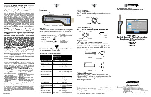
WGS/START HERE ARRO5WGS/START HERE ARRO6UWBT SERIESHandheld Bluetooth® Wireless Temperature,Humidity and pH Transmitter SeriesUWBT-TCUWBT-RTDUWBT-RHUWBT-PH WARRANTY/DISCLAIMEROMEGA ENGINEERING, INC. warrants this unit to be free of defectsin materials and workmanship for a period of 13 months from dateof purchase. OMEGA’s WARRANTY adds an additional one (1) monthgrace period to the normal one (1) year product warranty to coverhandling and shipping time. This ensures that OMEGA’s customersreceive maximum coverage on each product.If the unit malfunctions, it must be returned to the factory for evalua-tion. OMEGA’s Customer Service Department will issue an AuthorizedReturn (AR) number immediately upon phone or written request.Upon examination by OMEGA, if the unit is found to be defective, itwill be repaired or replaced at no charge. OMEGA’s WARRANTY doesnot apply to defects resulting from any action of the purchaser, includ-ing but not limited to mishandling, improper interfacing, operationoutside of design limits, improper repair, or unauthorized modifica-tion. This WARRANTY is VOID if the unit shows evidence of havingbeen tampered with or shows evidence of having been damaged as aresult of excessive corrosion; or current, heat, moisture or vibration;improper specification; misapplication; misuse or other operatingconditions outside of OMEGA’s control. Components inwhich wearis not warranted, include but are not limited to contact points, fuses,and triacs.OMEGA is pleased to offer suggestions on the use of its vari-ous products. However, OMEGA neither assumes responsibil-ity for any omissions orerrors nor assumes liability for anydamages that result from the use if its products in accordancewith information provided by OMEGA, either verbal or writ-ten. OMEGA warrantsonly that the parts manufactured bythe company will be as specified and free of defects. OMEGAMAKES NO OTHER WARRANTIES OR REPRESENTATIONS OFANY KIND WHATSOEVER, EXPRESSED OR IMPLIED, EXCEPTTHAT OF TITLE, AND ALL IMPLIED WARRANTIES INCLUDINGANY WARRANTY OF MERCHANTABILITY AND FITNESSFOR A PARTICULAR PURPOSEARE HEREBY DISCLAIMED.LIMITATION OF LIABILITY: The remedies of purchaser setforth herein are exclusive, andthetotal liability of OMEGAwith respect to this order, whether based on contract, warran-ty, negligence, indemnification, strict liability or otherwise,shall not exceed the purchase price of the component uponwhich liability is based. In no event shall OMEGA be liable forconsequential, incidental or special damages.CONDITIONS: Equipment sold by OMEGA is not intended to be used,nor shall it be used: (1) as a “Basic Component” under 10 CFR 21 (NRC),used in or with any nuclear installation or activity; or (2) in medical appli-cations or used on humans. Should any Product(s) be used in or withany nuclear installation or activity, medical application, used on humans,or misused in any way, OMEGA assumes no responsibility as set forthin our basic WARRANTY/DISCLAIMER language, and, additionally,purchaser will indemnify OMEGA and hold OMEGA harmless from anyliability or damage whatsoever arising out of the use of the Product(s)in such a manner.RETURN REQUESTS/INQUIRIESDirect all warranty and repair requests/inquiries to the OMEGACustomer Service Department. BEFORE RETURNING ANYPRODUCT(S) TO OMEGA, PURCHASER MUST OBTAIN ANAUTHORIZED RETURN (AR) NUMBER FROM OMEGA’S CUSTOMERSERVICE DEPARTMENT (IN ORDER TO AVOID PROCESSINGDELAYS). The assigned AR number should then be marked on theoutside of the return package and on any correspondence.FOR WARRANTY RETURNS,please have the followinginformation available BEFOREcontacting OMEGA:1. Purchase Order numberunder which the productwas PURCHASED,2. Model and serial number of theproduct under warranty, and3. Repair instructions and/orspecific problems relativeto the product.FOR NON-WARRANTY REPAIRS,consult OMEGA for current repaircharges. Have the followinginformation available BEFOREcontacting OMEGA:1. P urchase Order number to coverthe COST of the repair orcalibration,2. Model and serial number of theproduct, and3. R epair instructions and/or specificproblems relative to the product.OMEGA’s policy is to make running changes, not model changes,whenever an improvement is possible. This affords our customersthe latest in technology and engineering.OMEGA is a registered trademark of OMEGA ENGINEERING, INC.© Copyright 2017 OMEGA ENGINEERING, INC. All rights reserved.This document may not be copied, photocopied, reproduced,translated, or reduced to any electronic medium or machine-readableform, in whole or in part, without the prior written consent of OMEGAENGINEERING, INC.MQS5417/0717HardwareTransmitter DiagramRear LabelThe rear label is marked with international safety andhazard symbols in accordinance with IEC standards.you reach 20% battery level or lower.Transmitter LED Indication TableWiring DiagramsUWBT-TC-M12 WiringThe TC models use standard pin connections, as shownbelow:UWBT-RTD-M12 Wiringdiagram below:UWBT-RTD-TB Terminal Block WiringThe UWBT-RTD-TB comes with a 3-wire terminalblock. The terminal block can be unplugged from thebelow:POWER SWITCHOIMINI-B USB PAIR BUTTON GREEN LEDTC#2TC#2TC#1 –TC#1+PIN #1PIN #1PIN #3IEC SYMBOL:EU’s WASTE ELECTRICAL ANDELECTRONIC EQUIPMENTCOMPLIANCEIEC SYMBOL:CAUTION, REFER TOACCOMPANYINGDOCUMENTATIONAdditional InformationPlease visit the Omega website and download thefull-length UWBT manual for more information on theUWBT transmitter and its applications./uwbt/manuals/manualpdf/M5417.pdfThe Bluetooth® word mark is a registered trademark owned by Bluetooth SIG, Inc. andany use of such marks by OMEGA is under license.iOS is a trademark or registered trademark of Cisco in the U.S. and other countries and isused by Apple under license.Android is a trademark of Google, Inc.Other trademarks and trade names are those of their respective owners.RoHS 2 Compliant***********************®Servicing North America:U.S.A. Omega Engineering, Inc.Headquarters: Toll-Free: 1-800-826-6342 (USA & Canada only)Customer Service: 1-800-622-2378 (USA & Canada only)Engineering Service: 1-800-872-9436 (USA & Canada only)Tel: (203) 359-1660 Fax: (203) 359-7700e-mail:**************For Other Locations Visit /worldwideWGS/START HERE ARRO WGS/START HERE ARRO2WGS/START HERE ARRO34not mean that transmission is active. You must either bein the “Display” or “Settings” screens, or be loggingdata, for the Bluetooth® wireless transmission to beactive. Otherwise, the transmitter will unpair after 2minutes.smartphones or tablets. In order to view a transmitter’sinformation on a different tablet, you will need to unpairthe transmitter from the UWBT app.Software For (iOS)Initial Pairing InstructionsIn order to start communicating with the UWBTtransmitter, you need to pair it with your smartdevice via Bluetooth wireless communication. Fordevices that work with the iOS operating system,you must pair within the iOS settings beforepairing within the UWBT app. Devices for Androidonly require pairing from within the UWBT app.Pairing within smart device Settings menu (iOSonly):1. S witch on your UWBT transmitter.2. H old down the transmitter’s ‘Pair’ button for 2seconds – this will put the sensor in discoverymode.3. G o to the Settings page of your smart device4. S elect the Bluetooth wireless section5. M ake sure your Bluetooth wireless functionalityis turned on – the Bluetooth wireless slidershould be showing a green background.6. T ap the device to be paired via Bluetooth wirelesscommunication.Pairing Within the UWBT App:1. M ake sure your UWBT transmitter is switched onand that the Bluetooth wireless communication tothe smart device has already been established. See“Pairing within smart device Settings menu (iOSoperating system only)” in the previous section fordetails on this process.2. Open the UWBT app.3. I n the UWBT app, go to the ‘Transmitter Pairing’settings.4. I n the ‘Discovered Devices’ list, select the transmitteryou would like to pair with.5. Click on the ‘Pair’ button.6. Y ou are ready to display and log data!Software For (Android)Initial Pairing InstructionsIn order to start communicating with the UWBTtransmitter, you need to pair it with your smart devicevia Bluetooth wireless communication.Pairing within the UWBT App:1. M ake sure your UWBT transmitter is switched on.2. Open the UWBT app.3. I n the UWBT app, go to the ‘Transmitter Pairing’settings4. H old down the transmitter’s ‘Pair’ button for 2seconds – this will put the sensor in discovery mode.5. I n the ‘Discovered Devices’ list, select the transmitteryou would like to pair with.6. C lick on the ‘Pair’ button.7. T he smart device will create a prompt asking if youwould like to pair with the specific transmitter. Click‘Y es’. (Please note that this prompt only pops upduring your first time pairing with a transmitter.)8. Y ou are ready to display and log data!Software (PC)Installing the PC ApplicationT o install the UWBT PC application on yourcomputer follow these steps:1. D ownload the latest UWBT PC applicationrelease from our website at ftp://ftp.omega.com/public/DASGroup/products/2. A fter download is completed, open thedirectory where the download was saved3. C lick and run the UWBT PC app executablefile (.exe). The application and its drivers will beinstalled automatically.4. A fter application is fully installed, a shortcut iscreated on your computer desktop and “UWBTLibusb” directory is created in the C: drive ofyour PC. This directory contains the drivers forall UWBT transmitter models.Discover Transmitter:Clicking the “Discover Transmitter” buttonsearches for UWBT transmitters connected toUSB ports of the PC. The maximum number ofUWBT transmitters that can be discovered is four.After being discovered, only one UWBTtransmitter can be connected with the PC app at atime.• Y ou can connect to any of the discoveredtransmitters by clicking the “Select” button nextto the transmitter’s name.• Y ou can also switch the transmitter you areconnected to by clicking on the “Select” buttonnext to the new transmitter of your choice. Theapplication will automatically disconnect fromthe previous transmitter, and connect to the newThe “Discover Transmitter” button’s name changesto “Disconnect Transmitter” after a UWBT device isconnected.。
IND131&IND331使用说明书20090601

TH2811D使用说明书

第1章 准备使用1-31.1开箱检查1-3 1.2电源要求1-3 1.3电源和保险丝选择1-3 1.4周围环境1-3 1.5使用测试夹具1-4 1.6预热和连续工作时间 1-4 1.7仪器的其它特性1-4第2章 面板说明2-52.1前面板说明2-5 2.2后面板说明2-6 2.3显示区域定义2-7第3章 操作说明3-93.1开机3-9 3.2参数设定3-9 3.3频率设定3-10 3.4测试信号电压选择 3-10 3.5信号源内阻选择3-10 3.6测量速度选择3-10 3.7等效电路方式3-11 3.7.1设置串联与并联3-11 3.7.2选择串联或并联方式 3-11 3.8量程设定3-11 3.9开路清零3-12 3.10短路清零3-13第4章 基本性能指标4-144.1测量参数4-14 4.2等效方式4-14 4.3量程4-154.4 测试端方式4-15 4.5 测试速度4-15 4.6 基本精度 4-164.6.1 影响准确度的测量参数最大值、最小值 4-164.6.2 测量速度误差因子KS 4-164.6.3 测试电平误差因子KV 4-164.6.4 测试频率误差因子KF 4-164.7 测试信号频率4-16 4.8 测试信号电平4-17 4.9 输出阻抗4-17 4.10 测量显示范围4-17 4.11 清零功能4-17 4.12 量程保持4-17公公司司声声明明::本说明书所描述的可能并非仪器所有内容,同惠公司有权对本产品的性能、功能、内部结构、外观、附件、包装物等进行改进和提高而不作另行说明!由此引起的说明书与仪器不一致的困惑,可我公司进行联系。
第1章 准备使用本章讲述当您收到仪器后必须进行的一些检查,以及在安装使用仪器之前必须了解和具备的条件。
1.1 开箱检查感谢您购买和使用我公司产品,在您使用本仪器前请首先根据随机的装箱清单进行检查和核对。
若有不符可尽快与我公司联系,以维护您的权益。
FTW 171-3 FTW 172-3 KYOCERA 无线监控系统参考手册说明书

Flash Technology, 332 Nichol Mill Lane, Franklin, TN 37067(615) 261-2000FTW 171-3 / FTW 172-3 KYOCERAWireless Monitoring SystemReference ManualPart Number 7911713KYOCERAFront MatterAbstractThis manual contains information and instructions for installing, operating and maintaining the FTW 171-3 KYOCERA and FTW 172-3 KYOCERA Wireless Monitoring Systems. CopyrightCopyright © 2009, Flash Technology®, Franklin, TN, 37067, U.S.A.All rights reserved. Reproduction or use of any portion of this manual is prohibited without express written permission from Flash Technology and/or its licenser.Trademark AcknowledgementsFlash Technology® is a registered trademark name.ElectroFlash™, Flash Tech™, Flash Technology™, FTCA™, Flash™ and the Flash Technology Logo are all trademarks of Flash Technology.All trademarks and product names mentioned are properties of their respective companies and are recognized and acknowledged as such by Flash Technology.DisclaimerWhile every effort has been made to ensure that the information in this manual is complete, accurate and up-to-date, Flash Technology assumes no liability for damages resulting from any errors or omissions in this manual, or from the use of the information contained herein. Flash Technology reserves the right to revise this manual without obligation to notify any person or organization of the revision.In no event will Flash Technology be liable for direct, indirect, special, incidental, or consequential damages arising out of the use of or the inability to use this manual.WarrantyFlash Technology warrants all components, under normal operating conditions, for 1 year. ii Revision 3 – 8-21-2009 FTW 171-3/172-3 KYOCERATable of ContentsFTW 171-3 / FTW 172-3 KYOCERA (i)Front Matter (ii)Abstract (ii)Copyright (ii)Trademark Acknowledgements (ii)Disclaimer (ii)Warranty (ii)Table of Contents (iii)List of Figures .................................................................................................................................... i v List of Tables ..................................................................................................................................... i v Section 1 – Introduction . (5)Introduction (5)PLEASE NOTE (5)Description (5)Specifications (5)Section 2 – Initial On-Site Wireless Service Check (7)Unpacking (7)Important (7)Optional External Antenna (7)Section 3 – Mounting and Installation (8)Mounting (8)Installation (8)Wiring (8)Section 4 – Activation (14)Monitoring (14)Section 5 – Recommended Spare & Replaceable Parts (15)Customer Service (15)Ordering Parts (15)Disconnecting Power (15)Return Material Authorization (RMA) Policy (16)Return to Stock Policy (16)FTW 171-3/172-3 KYOCERA Revision 3 – 8-21-2009 iiiList of FiguresFigure 1-1 – FTW 171-3 / FTW 172-3 Internal Wiring & Component Layout (6)Figure 2-1 – Wireless Service Label (7)Figure 3-1 – AC Termination (8)Figure 3-2 – Dry Contact Input Label (8)Figure 3-3a – Enclosure Mounting Footprint (Vynckier) (9)Figure 3-3b – Enclosure Mounting Footprint (Stahlin) (10)Figure 3-4 – RS-485 Installation (12)Figure 3-5 – PCB 2903907 Layout and External Wiring (13)Figure 4-1 – Wireless Address (14)List of TablesTable 3-1 – PCB 9038 Medium Intensity TTB (11)Table 3-2 –PCB 2903907 LED’s (11)Table 5-1 – Replacement Parts (15)Table 5-2 – System Upgrade (For FTW 171 ONLY) (15)iv Revision 3 – 8-21-2009 FTW 171-3/172-3 KYOCERASection 1 – IntroductionIntroductionThis manual covers in detail the following two products: the FTW 171-3 and the FTW 172-3.The FTW 171-3 provides wireless monitoring through the use of four (4) dry contact inputs. The unit also monitors site power. Dry contacts are typically alarm relays provided by equipment for external monitoring of alarm conditions. Each input of the FTW 171-3 can be configured by the NOC to alarm on either open or closed status. Alarm on open is preferred for fail safe monitoring.The FTW 172-3 functions in the same manner as the FTW 171-3 but with the added benefit of RS-485 communication with Flash Technology lighting systems that are equipped with PCB 4747 or PCB 9038.Alarm and communication monitoring is handled by the Flash Technology National Operations Center (NOC). Additionally, the FTW 171-3 is RS-485 capable but not RS-485 enabled when shipped from the factory. Enabling the RS-485 on a FTW 171-3 will change the wireless monitoring unit to a FTW 172-3. If interested in upgrading, call the NOC at 1-800-821-5825 for assistance on this enhancement to your system.PLEASE NOTEBefore permanently installing and/or wiring the monitoring unit, power-up the system on-site to ensure wireless service in your area. Refer to Section 2 for detailed instructions. DescriptionThe component layout and internal wiring of the units are shown in Figure 1-1. The dry contact inputs are located on J2 of PCB 2903907 as shown in Figure 3-5. SpecificationsPhysical12H x 10W x 6D inches (Internal)10 lbs.ElectricalAC Voltage 120 VAC, 60 HzPower 7VA EnvironmentalStorage Temp -40 to 185F(-40 to 85C)Operating Temp -22 to 140F(-30 to 60C)FTW 171-3/172-3 KYOCERA Revision 3 – 8-21-2009 5Figure 1-1 – FTW 171-3 / FTW 172-3 Internal Wiring & Component Layout6 Revision 3 – 8-21-2009 FTW 171-3/172-3 KYOCERASection 2 – Initial On-SiteWireless Service Check UnpackingInspect shipping cartons for signs of damage before opening them. Check package contents against the packing list and inspect each item for visible damage. Report damage claims promptly to the freight handler.ImportantThe following steps will verify wireless service in your area and must be performed at the location where the unit is to be installed. A label located on the inside front cover of the monitoring unit is provided to call attention to this process. Figure 2-1 depicts the label noted above. Prior to installation, the on-site technician should apply 120 VAC to the unit and then monitor the green LED indicator labeled “ACTIVE” on PCB 2903907 for illumination. See Figure 3-5 for location of LED. If wireless service is available, the LED will blink indicating that the unit has connected to the wireless network. Once a wireless signal is found, the unit will then attempt to connect to Flash Technology’s National Operations Center (NOC). If communication is achieved, the “ACTIVE” LED will illuminate solid. This process may take several minutes. Upon successful completion of these steps, shut off power to the unit and proceed with installation. Optional External AntennaIf problems are encountered obtaining a signal, an optional external antenna is available with a 12’ cable. Refer to Recommended Spare Parts in Section 5 for ordering information. In some cases, it may be necessary to use a high gain antenna, such as a “Yagi Antenna”. Please contact Flash Technology for assistance or recommendation.Figure 2-1 – Wireless Service LabelFTW 171-3/172-3 KYOCERA Revision 3 – 8-21-2009 7Section 3 – Mounting and InstallationMountingThe base of the unit has four (4) mounting feet as shown in Figures 3-3a and 3-3b. Mounting hardware is not included.InstallationWiringConnect 120 VAC to the terminal block as shown in Figure 3-1, but leave power turned off until you are ready for activation (see Section 4).FTW 171-3 and FTW 172-3 Connect the equipment to be monitored via dry contact inputs as shown in Figure 3-5. A label has been provided on the inside cover of the unit to record each input, up to four (4), that is connected. Figure 3-2 depicts the dry contact input label.Figure 3-1 – AC TerminationFigure 3-2 – Dry Contact Input Label8 Revision 3 – 8-21-2009 FTW 171-3/172-3 KYOCERAFigure 3-3a – Enclosure Mounting Footprint (Vynckier)FTW 171-3/172-3 KYOCERA Revision 3 – 8-21-2009 910 Revision 3 –8-21-2009 FTW 171-3/172-3 KYOCERAFigure 3-3b – Enclosure Mounting Footprint (Stahlin)RS-485 Setup (FTW 172-3 Only) Connect the equipment to be monitored via RS-485 as shown in Figures 3-4. Figure 3-5 shows the layout of the PCB 2903907 board including the location of RS485 jumpers JP1 and JP2. No configuration of these jumpers is necessary.If the TTB in the last power converter in a chain has a PCB 4747, connect a 220 Ohm termination resistor at J9 terminals 1 and 2 on this TTB only. If the last power converter has a PCB 9038, refer to Table 3-1 below. All other power converters should have neither shunt installed.Table 3-1 – PCB 9038 Medium Intensity TTBTable 3-2 shown below describes the LED’s that are present on the PCB 2903907. The location of the LED’s is shown in Figure 3-5. Table 3-2 – PCB 2903907 LED’sFigure 3-4 – RS-485 InstallationFigure 3-5 – PCB 2903907 Layout and External WiringSection 4 – ActivationMonitoringOnce the installation is complete, follow the procedure below to activate the service and begin monitoring:1. Please be prepared to provide thefollowing information:The wireless address for this unit. See Figure 4-1. This label islocated on the inside front cover. Your name, contact number andcompany. If monitoring an FCC registered tower site, the site number andFCC number. Descriptions of the items being monitored by each input. 2. Re-apply power to the equipment and observe the “Active ” LED shown in Figure 3-5. The green LED should first blink when the unit has connected to the wireless network and illuminate solid when communicating with Flash Technology’s monitoring network . This process may take several minutes. 3. Connect the red wire to + (Positive) and the black wire to – (Negative) on the battery as shown in Figure 1-1. 4. Call 1-800-821-5825 to initiatemonitoring while on-site. The NOC technician will request several tests to be performed to verify correct installation and operation of the system. 5. Please note that once the unit is powered and communication isestablished, it will automatically send a message to the NOC to initiate service and billing will begin.Figure 4-1 – Wireless AddressSection 5 – Recommended Spare & Replaceable Parts Customer ServiceCustomer Service: (800) 821-5825Telephone: (615) 261-2000Facsimile: (615) 261-2600Shipping Address:Flash Technology332 Nichol Mill LaneFranklin, TN 37067Ordering PartsTo order spare or replacement parts, contact customer service at 1-800-821-5825.Disconnecting PowerWhen removing power from the equipment, ensure that the red wire to the battery is disconnected first.Return Material Authorization (RMA) PolicyIF A PRODUCT PURCHASED FROM FLASH TECHNOLOGY MUST BE RETURNED FOR ANY REASON (SUBJECT TO THE WARRANTY POLICY), PLEASE FOLLOW THE PROCEDURE BELOW:Note: An RMA number must be requested from Flash Technology prior to shipment of any product. No returned product will be processed without an RMA number. This number will be the only reference necessary for returning and getting information on the product’s progress.1. To initiate an RMA, customers should call Flash Technology’s Network Operation Center at (800-821-5825) to receive technical assistance and a Service Notification number. The following information is required before a Service Notification number can be generated:Site Name/Number / FCC Registration number/ Call Letters or Airport DesignatorSite Owner (provide all that apply – owner, agent or subcontractor)o Contractor Nameo Contractor CompanyPoint of Contact Information: Name, Phone Number, Email Address, Fax Number and Cell Phone (oralternate phone number)Product’s Serial NumberProduct’s Model Number or part numberService Notification Number (if previously given)Reason for call, with a full description of the reported issue2. The Service Notification number will then serve as a precursor to receiving an RMA number if it is determined that the product or equipment should be returned. To expedite the RMA process please provide:Return shipping methodPurchase Order (if non-warranty repair)Shipping AddressBill To AddressAny additional information to assist in resolving the issue or problem3. A P.O. is required in advance for the replacement of product that may be under warranty. Flash will then, at its discretion issue a credit once the validity of the warranty has been determined.4. A purchase order (P.O.) is also required in advance for all non-warranty repairs. NOTE: the purchase order is required prior to the issuance of the RMA number.If the P.O. number is available at the time of the call, an RMA number will be issued and the customer mustthen fax or email the P.O. with the RMA number as the reference, to ensure prompt processing.If the P.O. number is NOT available at the time of the call, a Service Notification Number will be given to the customer and should be referenced on the P.O. when faxed or emailed to RMA Rep.Flash will then, at its discretion repair or replace the defective product and return the product to the customer based on the shipping method selected.The customer may purchase a new product before sending in the existing product for repair. If FlashTechnology determines the existing product is still covered under warranty a credit will be issued to thecustomer for the new product.5. After receiving the Flash Technology RMA number, please adhere to the following packaging guidelines:All returned products should be packaged in a way to prevent damage in transit. Adequate packing should be provided taking into account the method of shipment.6. All packages should clearly display the RMA number on the outside of all RMA shipping containers. RMA products (exact items and quantity) should be returned to:Flash TechnologyAttn: RMA #XXX332 Nichol Mill LaneFranklin, TN 370677. All RMA numbers:Are valid for 30 days. Products received after may result in extra screening and delays.Must have all required information provided before an RMA number is assigned.Return to Stock PolicyParts can be returned within 60 days of ship date and will be subject to a 25% restocking fee. Product must:o Be in the original packagingo Not be damagedAfter 60 days no parts can be returned。
伟岸3351使用手册

S-PORT 串行通信口通过专用转接模块直接与计算机通信, 上位机界面可以完成比按键操作更多的功能。接专用 RS485 模块 可以实现数字信号远传,或构建 RS485 工业局域网。
简介
数字化 • 智能压力 / 差压变送器使用手册
数字化•智能压力 / 差压变送器是在采用世界先进的、成熟的、 可靠的电容传感器技术基础上,结合先进的单片计算机技术和传 感器数字转换技术精心设计而成的多功能数字化•智能仪表。
核心部件采用十六位单片机,其强大的功能和高速的运算能 力保证了变送器的优良品质。整个的设计框架着眼于可靠性、稳 定性、高精度和智能化,满足日益提高的工业现场应用之要求。 为此,软件中应用了数字信号处理技术,使其具有优良的抗干扰 能力和零点稳定性,且具备零点自动稳定跟踪能力(Z S C)和温 度自动补偿能力(TSC)。
数字化 • 智能压力 / 差压变送器使用手册
3.4 子菜单操作详细说明.......... 26 4 用户维护
4.1 概述................. 33 4.2 软维护................ 33 4.3 硬维护................ 34 4.4 故障排除............... 35 附录 A.1 性能指标............... 38 A.1.1 技术指标............. 38 A.1.2 使用条件............. 41 A.2 随机附件............... 42 A.3 注意事项............... 42
RealWear HMT-1Z1 T1100S 安全使用指南说明书

© 2019 RealWear Inc.v1.1 20190422https:///support ********************Safety Instructions HMT-1Z1 model T1100S1 NoteThis document contains the safety instructions necessary for the safe use of the HMT-1Z1 modelT1100S device in explosive and potentially explosive atmospheres. Such areas or zones are referred to as “ex-hazardous areas” in this document.2 IntroductionThis document contains information and safety regulations which are to be observed – without fail - for safe operation of the device under the described conditions. Non-observance of this information and instructions can have serious consequences and / or may violate regulations. Please read the manual and these safety instructions before using the device. In case of any translation or printing errors, the English version shall apply.3 Application3.1 ATEX & IECExThe HMT-1Z1 model T1100S is approved for use in zone 1, zone 2, zone 21 and zone 22 in accordance with directives 2014/34/EU (ATEX) and the IECEx System.3.2 NEC & CECThe HMT-1Z1 model T1100S is approved for use in Division 1 and 2 Class I, II, III.3.3 Manufactureri.safe MOBILE GmbH,i_Park Tauberfranken 1097922 Lauda-Koenigshofen; Germany4 Faults and DamageBefore entering ex-hazardous areas, the safety of the device must be checked. If there is any reason to sus-pect that the safety of the device has been compro-mised, it must be withdrawn from use and removed from any ex-hazardous areas immediately. Measures must be taken to prevent any accidental restarting of the device. The safety of the device may be compromised, if, for example:• Malfunctions occur.• The housing of the device shows damage.• The device has been exposed to excessive loads.• The device has been stored improperly.• Markings or labels on the device are illegible.• Permitted limit values have been exceeded.It is recommended that a device displaying errors or for which an error is suspected be sent back to an authorized service center to be checked.5 Ex-relevant / Intrinsic Safety RegulationsUse of this device assumes that the operator ob-serves the conventional safety regulations and has read and understood the user manual, safety instruc-tions and safety certificate. The following additional safety regulations must be complied with:5.1 Charging and battery• The device may only be charged outsideex-hazardous areas using the i.safe PROTECTOR1.0 USB-cable (or other e quipment approved byi.safe MOBILE GmbH.)• The device may only be charged at temperatures between +5°C and +40°C.• The battery is not removable by the user.5.2 Connections and covers• Physical connections to other equipment are only permitted outside ex-hazardous areas, using thei.safe PROTECTOR 1.0 USB-cable (or otherequipment approved by i.safe MOBILE GmbH.)• Inside ex-hazardous areas the covers of the Micro USB c onnector and the Micro SD card slot must be kept closed.• The audio jack can be used to connect approved headsets inside ex-hazardous areas.• To ensure the integrity of ingress protection (IP),check that all gaskets are present and functional.• During charging any headset or accessory must be unplugged from the audio jack.5.3 Usage environments• The device may not be taken into zones 0 or 20.• The device may not be exposed to any aggressive acids or alkalis.• The device must be protected from impactswith h igh impact e nergy, against excessive UVemission and high electrostaticcharge processes.• The permitted ambient operating temperaturerange is -20°C to +60°C.5.3 Accessories• Only accessories approved by i.safe MOBILEGmbH may be used.• Adjustment of the head strap in ex-hazardousareas is not permitted.Device Overviewport locatedunder coverUsing the HMT-1Z1 with a Hard HatTo get hard hat clips, visit .1. Hook the Hard Hat Clips into the HMT-1Z1 band and snap them into place.2. Slide the clips into the hard hat accessory slots; the HMT-1Z1 band should sitoutside of the hard hat’s harness.3. Put on the hard hat and if applicable, tighten until secure and comfortable.4. To remove the HMT-1Z1 from the hard hat, pinch the clip fingers and push the clip out ofthe hard hat slots.IEUsing the HMT-1Z1 without a Hard HatAttaching the Head StrapAttaching the Rear PadThe Rear Pad snapsonto the HMT-1Z1’srear band; align theopenings on the RearPad to the pegs onthe HMT-1Z1’s rearband, and snap intoplace.Insert the end of thestrap into the insideslot on both sidesof the HMT-1Z1 asshown. Fold the endback on itself andsecure using thevelcro patch.Charging the HMT-1Z11. Connect the Micro USB charging cable as shown.2. Connect the cable to the wallcharger as shown and plug in.A Red light means the battery is ex-tremely low or dead.A Yellow light means the battery is less than 100% and charging.A Green light means the battery is full.The USB cable included with the HMT-1Z1 is a special micro-USB cable for data transfer and charging. It includes a safety box that protects the HMT-1Z1’s safety circuits from power surges. These surges can damage the HMT-1Z1 and may occur when connecting the HMT-1Z1 to computers, wall chargers, carchargers, and other power sources that are not certified or approved as intrinsically safe. It is the only cable approved for charging the HMT-1Z1 and for moving files to and from the HMT-1Z1.Generate a QR Code for Configuration11. Go to realwear from your computer or mobile device.2. Select Configuration .3. Follow the prompts to enter information andgenerate a QR Code.1. Download the RealWear Companion app from the G oogle Play or Apple App Store.2. Launch RealWear Companion from your smartphone.3. Select Configuration .4. Select First Time Setup .5. Follow the steps in the application in enter information and generate a QR Code.Scan this code from your smartphone to download RealWear Companion.Use the RealWear Companion AppUse ORPut on the HMT-1Z1235678910Do not extend the display too far from your eye. Keep the display as close to the eye as possible for thebest viewing experience. Adjust the overhead strap such that the HMT-1Z1 rests horizontally, slightly abovethe tops of your ears. Position the shoulder and elbow joints into a “Z” shape, below the line of sight, left or right eye.Eye dominance is the tendency to prefer visual input from one eye to the other. Most people areright-eye dominant; however in a small portion of the population neither eye is dominant. It is best to use your dominant eye when viewing the display.To determine which eye is dominant 1. Form a triangle with your hands placed together at arms length. 2. With both eyes open, focus on any distant object centered in the triangle.3. Maintaining focus on the object centered in the triangle, close your right eye. If the object is still in the triangle, you are left eye dominant.4. Maintaining focus on the object centered in the triangle, close your left eye. If the object is still in the triangle, y ou are right eye dominant.5. If the object is in the triangle with either eye then you a re dominant eye neutral.6.Repeat test to confirm.Check your eye dominance245678910Press and hold thepower button for 3seconds to turn on the device.Rotate camera up/down to get the best view.Adjust display pod so you can clearly see all 4 corners of the display and then lock into position using ring.Turn on the HMT-1Z1346789101. The HMT-1Z1 will automatically launch into configuration mode.2. Point the camera at the QR code you generated in Step 1.3. The HMT-1Z1 will detect the QR code and configure the device.The HMT-1Z1 is controlled by voice and head motion.Say what you see on the screen and move your head to navigate. If you get stuck say “SHOW HELP”.Say What You See568910Scan the Configuration QR Code from the HMT-1Z14578910Note: Once the device connects to WiFi an update of RealWear Device Agent may occur.Note: To change your language, press and hold theaction button on the side of the HMT-1Z1. The language selection will switch automatically, let go of the button when the language you want is selected.i.safe MOBILE GmbHi_Park Tauberfranken 1097922 Lauda-Koenigshofen; Germany。
梅特勒托利多IND131-331称重显示控制器使用说明书(1)

梅特勒托利多IND131-331称重显示控制器使用说明书(1)附录E树形菜单结构图参数设定表F1F2F3F4F5CommunicationScale秤台Application应用Terminal仪表通讯Maintenance维护gF1.1F2.1F3.1F4.1F5.1TargetOperationOutputTemplateScaleDiagnosticsType类型预置点设置SerialNumber序列号秤的诊断输出模板F1.1.1F2.1.1F3.1.1F4.1.1F5.1.1ToleranceTypeSerialNumberLoadCellOutputName名称允差类型序列号Format格式传感器输出.F1.1.2F2.1.2F3.2F4.1.2F5.1.2OutputTypeScreenSaverPrintScaleNameCalibrationValuesApproval认证输出类型屏保打印秤名称标定值F1.2F2.1.3F3.2.1F4.2F5.1.2.1Capacity&Increment量程与分度值TargetSource目标值数据源ScreenSaverConnections通讯接口连接ZeroCounts屏保零点内码F1.2.1F2.1.4F3.3F4.2.1F5.1.2.2Units单位TargetLatching目标值锁存Region区域COM1Assignment串口1应用TestLoad1砝码1值3F1.2.2F2.2F3.3.1F4.2.1.1F5.1.2.3TestLoad1CountsCapacity量程TargetValues预置点MenuLanguage快捷操作菜COM1Checksum校验和砝码1内码F4.2.2F1.2.3F2.2.1F3.3.2F5.1.2.4单语言COM2AssignmentIncrement分度值T argetSetupLanguage设置菜单语言串口2应用TestLoad2砝码2值目标值F1.2.4F2.2.2F3.4F4.2.2.1F5.1.2.5COM2ChecksumTestLoad2Counts×10Always10倍扩展-TolUser用户校验和砝码2内码负允差F1.3F2.2.3F3.4.1F4.3F5.1.3PasswordProtectionCalibration标定+T ol正允差密码保护Serial串口Statistics统计F1.3.1F2.2.4F3.4.2F4.3.1F5.1.3.1LinearityPasswordCOM1Weightments线性Spill提前量密码串口1称重次数F1.3.2F2.2.5F3.5F4.3.1.1F5.1.3.2SetZero标定零点MenuKeys快捷操作菜单BaudRate波特率Overloads过载次数FineFeed细喂料F1.3.3F2.3F3.5.1F4.3.1.2F5.1.3.3SetSpan标定量程ComparatorsCalibrationAccess访问标定DataBits数据位Peakweight最大称重比较器F1.3.4F2.3.1F3.5.2F4.3.1.3F5.1.3.4逐步替代法标定Comparator1Source比较器1数据源ZeroCommandsStepCalTargetAccess访问目标值Parity奇偶校验清零指令F1.3.5F2.3.2F3.5.3F4.3.2F5.1.3.5Comparator1ActiveComparatorAccessZeroFailures CalFREE免标定比较器1算子访问比较器COM2串口2清零失败COM2/F1.4F2.3.3F3.6F4.3.2.1F5.2ZeroResetBaudRateSerialTest清零Limit1下限1复位并行波特率串口测试F1.4.1F2.3.4F4.3.2.2F5.2.1输入AutoZero自动清零HighLimit1DataBits数据位COM1串口1 上限1输出F1.4.2F2.3.5F4.3.2.3F5.2.2DeviceNetAutoZeroRangeComparator2Source自动清零范围比较器2数据源选件Parity奇偶校验COM2串口2 F1.4.3F2.3.6F4.3.2.4F5.3选件PowerUpModeComparator2ActiveDiscreteI/OTest开机模式比较器2条件Interface接口输入输出(DIO)测试F1.4.4F2.3.7F4.4F5.4DisplayTest显示屏测试式UnderZeroBlanking欠载范围Limit2下限2PLCPLC7F5.5F1.4.5F2.3.8F4.4.0SoftwareUpdate软件升级PowerUpZeroF1开机清零HighLimit2上限2PLCTypePLC类型F5.6F1.4.6F2.3.9F4.4.1Reset复位PushbuttonZero按键清零Comparator3Source比较器3数据源AnalogOutput模拟量输出F2.3.10F4.4.1.1F1.5Comparator3Active比较器2条件Source数据源Tare去皮F2.3.11F4.4.1.2模拟量输出选件F1.5.1ZeroValues零点值Limit3下限3PushbuttonTare按键去皮F2.3.12F4.4.1.3F1.5.2FullSpanValueHighLimit3上限3满量程值NetSignCorrection负净重修正F2.4F4.4.1.4F1.6CalibrationOutputDiscreteI/O输入输出(DIO)标定输出Rate流量F2.4.1F4.4.1F1.6.1DiscreteInputsA-BRIOA-BRIO输入(IO)WeightUnits重量单位F2.4.1.1F4.4.1.5F1.6.2Input1PolarityNodeAddress节点地址输入1极性TimeUnits时间单位F2.4.1.2F4.4.1.6F1.6.3Input1Assignment输入1应用StartQuarter起始组MeasurementPeriod测量时间F2.4.1.3F4.4.1.7F1.6.4Input2Polarity输入2极性LastRack终结机架OutputAverage输出平均值A-BRIO选件F2.4.1.4F4.4.1.8F1.7Input2Assignment输入2应用DataRate数据传输速率Filter滤波F2.4.2F4.4.2F1.7.1 DiscreteOutputsDataFormat输出(DO)数据格式LowPassFilter低通滤波F2.4.2.1F4.4.2.1F1.7.2Output1AssignmentFormat格式输出1应用StabilityFilter稳态滤波F2.4.2.2F4.4.2.2F1.8Output2AssignmentByteOrder字节顺序输出2应用Stability稳态F2.4.2.3F4.4.1F1.8.1Output3Assignment输出3应用PROFIBUSPROFIBUSPROFIBUSMotionRange动态范围F2.4.2.4F4.4.1.5F1.9Output4Assignment输出4应用NodeAddress节点地址PROFIBUS选件LogorPrint日志或打印F2.5F4.4.2F1.9.1DataFormatReset复位数据格式AutoPrint自动打印F4.4.1F1.10 DeviceNetDeviceNet1Reset复位F4.4.1.5DeviceNNetodeAddress节点地址DeviceNet选件F4.4.1.9DataRate数据传输速率F4.4.2DataFormat数据格式F4.5Reset复位136。
Cerabar T PMC131 绝对和压力测量传感器技术数据手册 TD 042E US ae 10

Pressure transmitters for absolute and gauge pressure measurementCerabar T PMC131Technical Datasheet TD 042E/US/ae/10.09US/INDD CS• Rugged ceramic sensor withstands corrosion and abrasion • Can withstand up to 40 times overload at peak pressures • Reliable with long-term stability • Suitable for vacuum applications • Dry (oil-free) measurement cellApplicationThe Cerabar T PMC131 allows measurement of absolute and gaugepressure in liquids, vapors and gases. Safe operation is guaranteed by special long-term stability and overload resilience of the capacitance ceramic sensors. This instrument is a pressure transducer equipped with a highly accurate capacitance ceramic sensor. The ceramic sensor is very resistant to corrosion and abrasion. It is especially suitable for measurement of absolute and gauge pressure ranges between 0 to 5 psi and 500 psi.Measurement principleThe measurement pressure causes a slight deflection of the sensor diaphragm. The change in proportion to pressure is measured and isavailable as a 4 to 20 mA output signal. The pressure transducer comes with a plug connection (ISO 4400) for wiring to an external loop-power supply (e.g. an RNS221 power supply from E-direct).Measurement systemCerabar T pressure transducer with 4 to 20 mA output and external power supply, such as RNS221 from E-direct.Application exampleCerabar T pressure transducer and external power supply, such as RNS221 and remote display unit from E-direct.Power SupplyPMC131RIA261-C2K DisplayRNS221-AK Power SupplyAnalog output 4 to 20 mA to PLCProduct:liquids, vapors and gases Measuring cell:Dry (oil-free) ceramic cell Overload stability:up to factor 40 Measuring range (limits): -0.29 to 580 psi Product temperature: -4 to +212°FAccuracy:< 0.5 %PMC131/plug/pressure gauge connectionPMC131 cable connection1) FS = Full Scale = Measuring range Dimensions in inches (mm) and materials PMC131/plug/pressure gauge connectionPMC131 cable connectionTechnical dataGeneral•O utput signal 4 to 20 mA/two-wire•M ax. load R a R a [Ω] ≤ (U b -11 V)/0.02 AAccuracy•M easurement accuracy Reference conditions according to DIN IEC 770;< 0.6% FS1) (linearity including hysteresis andrepeatability)•E ffect of ambient temperature in relation to nominal value Zero point: typ. < 0.15%/10 K Range: typ. < 0.1%/10 K•L ong-term stability< 0.15% FS1) per year•R esponse time T9040 msOperating conditions•M aterial temperature-4 to +212°F•A mbient temperature-4 to +185°F•S torage temperature-58 to +212°F•C limate class4K4H according to DIN EN 60721-3•P rotection NEMA 4 w/plug; NEMA 6 w/cable •V ibration stability4M5 according to DIN EN 60721-3•E lectromagnetic compatibility Interference emission according to EN 50081-1, Interference emission according to EN 50082-2, 10 V/m according to EN 61000-4-3Mechanical construction•P rocess connection½” MNPT with ¼” FNPT•M aterials in contact with medium Process connection and housing: 304 SS Seal (internal location): FPM (Viton)•P rocess diaphragm Al203 (aluminum oxide ceramic)•E lectrical connection4-pole plug connection according to ISO 4400with ½” NPT conduit entry or 15 ft. fixed cable, 3conductor with pressure compensation line Power supply U b•S upply voltage11 to 30 V DC at 5% waveElectrical connection Plug versionVersion with 2-wirem n o not assigned * Ground (PE)HousingSeal– Insert the MINIDIS display n between the plug o and plug base m of the sensor.– Replace the screw p with the extended screw included in the package.– Place seals (included) between sensor/MINIDIS display and MINIDIS display/plug – The display can be rotated 90°– A sticker which is included in the package andcontains information on the engineering units can be affixed beneath the LED display.Mechanical connection (display rotated 90° compared to delivery status). Image showsPMP131; MINIDIS may be installed on PMP131 or PMC131.½” MNPT and ½” FNPTAccessories - MINIDIS display for plug version • D isplay4 digits, red LED, loop powered to use in 4 to 20 mA loops, angular connector DIN 43650 0.3” (7.62 mm) display height, turnable in angle of 90°• D isplay range -1999 to +9999, programmable by two buttons • P rotection classNEMA 4• M aterial plastic PA6 GF30, face plate PMMA • V oltage drop ≤ 5 V (equivalent burden of max. 250 Ω)• T emperature range 32 to 140°F (0 to 60°C) Ambient • P rogrammingBy means of two keys, menu-guided; display scale, decimal point, damping, error message • D imensions• I nstallation of MINIDISin inches (mm)* please add code for measuring rangeMeasuring range, Unit Overload Code Gauge pressure (psi)Q4F 0 to 5 psig 100 psi Q4H 0 to 15 psig 150 psi Q4N 0 to 50 psig 300 psi Q4R 0 to 150 psig 600 psi Q4T 0 to 500 psig 850 psiplease add to `Order No.´Measuring rangesfor Cerabar T PMC131 plug versionMeasuring range, Unit Overload Code Gauge pressure (psi)Q4H 0 to 15 psig 150 psi Q4R 0 to 150 psig6000 psiplease add to `Order No.´for Cerabar T PMC131 cable version Many other models, versions and options are available. Please contactEndress+Hauser for more information.Acceptance per our Standard Terms and Conditions (find at ).Total price:FOB Greenwood, IN; shipped pre-paid; shipping charges and applicable taxes added to invoice.$__________E-direct catalog (free)Online Shop WarrantyDeliveryOrder:by phone by fax Should an instrument fail during the 1year warranty period,areplacement unit will be provided.Shipment from receipt of order for quantities 1–3within 2business days.800-321-7754888-EH DIRECT(343-4732)For specialrequests,e-mail us:*******************.com(For customers in the USA only)E-directEndress+Hauser,Inc.2350Endress Place Greenwood,IN 46143Online Shop WarrantyDeliveryOrder:by phone by fax Should an instrument fail during the 1year warranty period,areplacement unit will be provided.Shipment from receipt of order for quantities 1–3within 2business days.800-321-7754888-EH DIRECT(343-4732)For specialrequests,e-mail us:*******************.com(For customers in the USA only)。
施耐德WIFER Quick Start guide - WIFER TCSEGWB131W 说明书
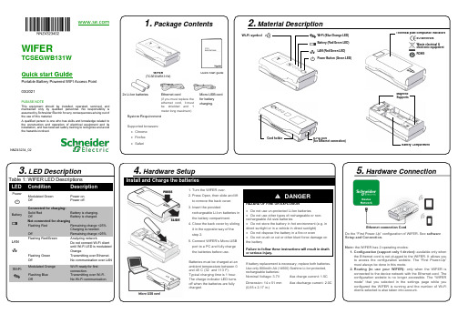
4. Hardware SetupInstall and Charge the batteries1. Turn the WIFER over.2. Press Open, then slide and liftto remove the back cover.3. Insert the providedrechargeable Li-Ion batteries inthe battery compartment.4. Close the back cover by slidingit in the opposite way of thestep 2.5. Connect WIFER’s Micro-USBport to a PC and fully chargethe batteries before use.Batteries must be charged at anambient temperature between 0°and 45°C (32° and 113°F).Typical charging time is 1 hour.The charge indicator LED turnsoff when the batteries are fullycharged.DANGERHAZARD OF FIRE OR EXPLOSION•Do not use un-protected Li-Ion batteries•Do not use other types of rechargeable or non-rechargeable AA size batteries•Do not store the battery in hot environment (e.g. indirect sunlight or in a vehicle in direct sunlight)•Do not dispose the battery in a fire or oven•Do not crush or cut or other blunt force damage onthe batteryFailure to follow these instructions will result in deathor serious injury.If battery replacement is necessary, replace both batteries.Use only 800mAh AA (14500) Soshine Li-Ion protected,rechargeable batteries:Nominal Voltage: 3.7V Max charge current: 1.5CDimension: 14 x 51 mm(0,55 x 2,17 in.)Max discharge current: 2.0C3. LED DescriptionTable 1: WIFER LED DescriptionsLED Condition DescriptionPowerModulated GreenOffPower on.Power off.BatteryConnected for charging:Solid RedOffNot connected for charging:Flashing RedOffBattery is charging.Battery is charged.Remaining charge <25%Charging is needed.Remaining charge >25%LANFlashing Red/GreenFlashing GreenOffAnalyzing network.Do not connect Wi-Fi clientuntil Wi-Fi LED is modulatedOrange.Transmitting over Ethernet.No communication over LANWi-Fi Modulated OrangeFlashing BlueOffWi-Fi ready for firstconnection.Transmitting over Wi-Fi.No Wi-Fi communication.1. Package ContentsWIFER(TCSEGWB131W)Quick Start guide2x Li-Ion batteries Ethernet cord(if you must replace theethernet cord, it mustbe shielded and 1meter long maximum)Micro-USB cordfor batterycharging.System RequirementSupported browsers:•Chrome•Firefox•SafariWIFERTCSEGWB131WQuick start Guid ePortable Battery Powered WIFI Access Point03/2021PLEASE NOTEThis equipment should be installed, operated, serviced, andmaintained only by qualified personnel. No responsibility isassumed by Schneider Electric for any consequences arising out ofthe use of this material.A qualified person is one who has skills and knowledge related tothe construction and operation of electrical equipment and itsinstallation, and has received safety training to recognize and avoidthe hazards involved.2. Material DescriptionNNZ43234_02Wi-Fi symbol Wi-Fi (Blue/Orange LED)Battery (Red/Green LED)LAN (Red/Green LED)Power Button (Green LED)Technical plate compliance indicatorsEU directivesWaste electrical &electronic equipmentROHSCord holder RJ-45 port(for Ethernet connection)MagneticSupportsBattery Compartment5. Hardware ConnectionDo the “First Power-Up” configuration of WIFER. See softwareSetup and Connection.Note: the WIFER has 2 operating modes:1. Configuration (support only 1 device): available only whenthe Ethernet cord is not plugged to the WIFER. It allows youto access the configuration website. The “First Power-Up”must always be done in this mode.2. Routing (to use your WIFER): only when the WIFER isconnected to the device network with the Ethernet cord. Theconfiguration website is no longer accessible. The “WIFERmode” that you selected in the setting s page while youconfigured the WIFER is running and the number of Wi-Ficlients selected is also taken into account.Ethernet connection Cordis not available until the first power-upOrange, select the SSID for your WIFERThe X corresponds to the last 5 digits ofthe serial number of your WIFER (on theTroubleshootingWi-Fi & Ethernet LED are flashing fast & authentication processThe Wi-Fi LED (Orange/Blue) and Ethernet LED (Red/green) are flashing fast, it is indicating a detected error.The network is full, WIFER does not find IP addresses available for itself and for the client devices.The network is almost full and small, also WIFER has some difficulty to launch the scanning process.In both cases, it is due to a non-conformity between WIFER and the target network.and reboots before the end of a network network scan.mode. This requires knowledge of the network IP 9. Cyber securityIn terms of security practices, we advise you to:•set the operating distance to the lowest value.•set the number of device connections to the exactnumber of devices you will connect.Note:In static Mode, the users must configure the WIFER under the system administrator responsibility. If configured static addresses are already used by other devices on the network, the WIFER will significantly disturb this one.NNZ43234_02 – 03/2021。
DATA HARVEST 智能无线电压电流传感器 1130 1131 使用指南说明书

Smart Wireless VoltageCurrent SensorProduct No. 1130 ±20 V and ±1 A (±1000 mA) Product No. 1131 ±5 V and ±0.1 A (±100 mA)Data Harvest Group Ltd.1 Eden Court, Leighton Buzzard, Beds, LU7 4FYTel: 01525 373666, Fax: 01525 851638e-mail:*************************************************.ukData Harvest. Freely photocopiable for use within the purchasers establishmentContentsIntroduction .......................................................................................................................................... 2 The Smart Wireless Voltage - Current sensor ...................................................................................... 2 Connecting the Voltage - Current sensor to a computer ..................................................................... 3 Measurement procedure ..................................................................................................................... 4 Practical information ............................................................................................................................ 6 Manually calculating Resistance or Power ........................................................................................... 7 Specifications ........................................................................................................................................ 8 Batteries ............................................................................................................................................... 9 Updating the Firmware ........................................................................................................................ 9 Hard Reset ............................................................................................................................................ 9 Investigations ..................................................................................................................................... 10 Magnetic induction ....................................................................................................................... 10 Charge stored on a capacitor ........................................................................................................ 12 Start-up current of a bulb ............................................................................................................. 13 Limited warranty .. (14)IntroductionThe Smart Wireless Voltage - Current sensor is both USB and Bluetooth compatible. Using Bluetooth the sensor can wirelessly connect to mobile devices such tablets and mobile phones as well as desktop or laptop computers giving students the ability to run experiments independently without being tethered to a traditional data logger. See the EasySense2 user manual system requirements for further details. The Voltage - Current sensor is a combined voltage and current sensor in one package. It can be used to measure both electric current and the potential difference across a component in low voltage AC or DC circuits.The four 4 mm sockets (2 for Voltage and 2 for Current) allow for connection to most standard available electronics kits and school based power supplies using 4 mm plug leads (not supplied). The sensor is supplied with a mini USB lead (1 m standard A to standard mini B).The Smart Wireless Voltage - Current sensorCharge the sensor fully before first useStatus lightOn/Off switch USB inputUnique ID number2 x 4 mm sockets for measuring voltage (V) 2 x 4 mm sockets for measuring current (I)Use the USB lead supplied to connect the sensor either direct to a USB port on your computer* or to a USB mains charger that outputs 5 V at 500 mA or more. A full charge can take up to 4 hours.*Or a powered USB hub. Your computer should be turned on and not in sleep or standby mode or the battery may drain instead of charge.To switch the sensor off: Press and hold down the On/Off switch for about 2 seconds until the white light is lit solidly then release.If not communicating with the EasySense2 software the sensor will put itself to sleep after a period of about one hour of inactivity (blue LED flashing).Connecting the Voltage - Current sensor to a computerBluetooth users:Do NOT pair devices(if paired the sensor will not be available to the EasySense2 software). Computers or devices will need to support Bluetooth Low Energy (BLE), for further information refer to the instructions provided for the EasySense2 software.Install the EasySense2 software, if it is not already on your computer. For details of how to install and operate this app, please refer to the instructions provided for the EasySense2 software.If connecting via USB:This sensor can be used like a traditional data logger connected via USB.Step 1: Connect the sensor to the computer’s USB port using the USB cable supplied. The computer will automatically detect a new device and install the drivers. The status light on the sensor will flash whiteto show it is charging.Step 2: Open the EasySense2app.Lab Setup will open showing the sensor as connected(Devices icon green).The status light on the sensor will flash green to indicatea connection is established.If connecting via Bluetooth:Step 1: Short press the On switch, the blue LED will flash. Step 2: Open the EasySense2 app.Step 3: Lab Setup will open, select the red Devices icon.Step 4: Select to connect to the sensor (the list will show the ID number printed on the sensor).The Devices icon will change to green and the status light on the sensor will flash green to indicate a connection has been established.Tap or click on the slide switch to switch sensors on or off. A grey slide switch indicates the sensor is off so no readings will be taken from this sensor.Click or tap on to close the box.When you have finished use of the sensor select Devices and Disconnect.To add another data logger or smart wireless sensorOnly one USB device can be connected at the same time and it will be added automatically.For Bluetooth or Wi-Fi devices select the Devices icon (top left of screen) then the Connect button for the device from the list of those available.TroubleshootingIf the sensor loses Bluetooth connection and will not reconnect try∙ Closing and reopening the EasySense2 software.∙ Close the EasySense2 software. Switch the sensor Off and then On again (To switch off : Press and holddown the On/Off switch for about 2 seconds until the white light is lit solidly then release. To switch back on: Press the On/Off switch (blue LED will flash). Reopen the EasySense2 software.∙ If you are using a Bluetooth Smart USB Adaptor unplug the adaptor, plug back in again and try toreconnect.∙Hard reset the sensor and then try to reconnect, see page 9.Measurement procedureConnectSlide switches indicate that the Voltage sensor is On and the Current sensor is Off∙ Connect the Voltage - Current sensor to the EasySense2 software.∙Voltage, referred to as potential difference or electromotive force (e.m.f.) is the electrical potential energy between two points in a circuit and is the driving force pushing the electricity around a circuit.Connect 4 mm leads from the V red and black socket in parallel with a component. Voltage is measured with respect to the negative socket and not to circuit ground, this allows connection without the constraints of common grounding.∙Current is the rate of flow of electrical charge past a point per second.Connect 4 mm leads from the I red and black socket in series with the circuit component through which the current is to be measured.∙ The sensors measure from positive to negative as positive. Observe the correct polarity e.g. the leadfrom the black socket to the negative terminal of the cells.Positive+Resistive load e.g. lamp, resistor, etc.BatteriesNegativePositiveResistive load e.g. lamp, resistor, etc.BatteriesNegativeAV Batteries∙ If the Voltage sensor is not part of a complete circuit, then data collected may appear ‘noisy’. To measure voltage accurately you need an impedance (resistance), the Voltage sensor is a high impedance device and will pick up any electrical ‘noise’.Note: To demonstrate zero impedance, short out a Voltage sensor by connecting its black & red plugs together .∙ The Current sensor has a very low resistance so it will introduce as little resistance as possible to the circuit. ∙ An alternative to batteries is to use a fully isolated mains power supply with a regulated DC output (smoothed and fully rectified). Be aware that some power supplies are ½ wave rectified producing an average rather than true DC. The sensors will ‘pick up’ the fluctuations in voltage and current from this type of power supply.Log of the voltage and current supplied by a ½ wave rectified power unit (voltage fixed at 4.5 V)∙ The suitability of components can be checked using Ohms law.The sensor most suitableCurrent (I) = Voltage (V) Resistance (R)∙ When large quantities of cells are used in a circuit the current flow can cause low value resistors to become very hot (W = V x I).For example: A 100 Ω 3 W resistor give s good results without too much heat.∙ 6 V supply with 10 Ω resistor = 0.6 A (600 mA) current flow (Power 0.6 x 6 = 3.6 W). ∙ 6 V supply with 50 Ω resistor = 0.12 A (120 mA) current flow (Power 0.12 x 6 = 0.72W). ∙ 6 V supply with 100 Ω resistor = 0.06 A (60 mA) current flow (Power 0.06 x 6 = 0.36W ).∙The Current sensor is protected to a voltage of ±13 V, so as long as the voltage on its inputs are below this value the sensor will not be damaged.∙ The maximum working voltage of the Current sensor is ±13 V.If you measure current in the return wire (i.e. the 0 V wire) the voltage will be much lower and more likely to be within safe limits.∙ The operating range of the sensor is 0 to 40˚C and 0 to 95% RH (non -condensing). Do not subject to extreme heat or cold. Do not expose to direct sunlight for extended periods of time. ∙ The sensor is not waterproof. It may be cleaned using a damp cloth. Do not immerse in water or detergent. Do not place the sensor in an environment in which high humidity levels are possible as this may result in damage or malfunctionManually calculating Resistance or PowerResistance and Power can be calculated from Current and Voltage data.Resistance∙ Select the Calculate icon. ∙ Select Add Series .∙ Enter Resistance as the name∙ Increase the number of decimals as appropriate e.g. 3 ∙ Enter the series unit as Ohm . ∙ Select ax/by as the Formula.∙ Enter 1 as the value for ‘a’, and 0.001 as value for ‘b’ (to convert mA readings into A). ∙ Select Voltage as the series for x and Current as the series for y and Apply .Current sensor connected before the resistor so voltagewill be higherPower supplyRCurrent sensor connected after the resistor so voltage will be lowerPower∙ Select the Calculate icon. ∙ Select Add Series . ∙ Enter Power as the name∙ Increase the number of decimals as appropriate e.g. 3 ∙ Enter the series unit as W . ∙ Select axy as the Formula.∙ Enter 0.001 as value for ‘a ’ (to convert mA readings into A).∙ Select Current as the series for x and Voltage as the series for y and Apply .Graph showing the result from a resistance investigation using a 47 Ω resistorSpecificationsConnectivity: USB or BluetoothFastest logging speed: Bluetooth & USB = 20,000 samples per second (interval 50 µs) Memory approx. 65 k samples, shared between the Voltage and Current channels. Firmware upgradeableUSB communication to PC: Full speed compliant Power specifications: 5 V at 500 mAPress and hold down the On/Off button for at least 8 secondsRelease when LED gives a flash of BLUE lightBattery: rechargeable internal lithium-ion 3.7 V, 1300 mAh Operating range: 0 - 40˚C and 0 to 95% RH (non -condensing) Weight: approx. 82 gExternal dimensions: approx. height 33 mm x width 50 mm x length 92 mmBluetoothBluetooth 4.2 low energy radio, single mode compliant Transmit (TX) power: 0 dBm Receiver (RX) sensitivity: - 90 dBmUsable transmission range: up to 10 m in open air Frequency Range: 2.402 to 2.480 GHz operationBatteriesThe Voltage - Current sensor is fitted with a rechargeable lithium-ion battery. Whenever the sensor is connected to the USB port on the computer or to a USB mains charger (output 5 V at 500 mA or more), it will automatically re-charge the battery (LED status flashing white).The sensor will stay awake for 60 mins when Bluetooth advertising (LED status flashing blue).Once connected to the EasySense2 software (LED status flashing green) the sensor will stay awake until the battery loses charge.To switch Off: Press and hold down the On/Off switch for about 2 seconds until the white light is lit solidly then release.Lithium-ion batteries are ‘memory -free’ and prefer a partial rather than a full d ischarge. Constant partial discharges with frequent recharges will not cause any harm. Frequent full discharges should be avoided whenever possible. Ideally the sensor should be stored at about 40% or more charge.The speed at which a lithium-ion battery will age is governed by both its storage temperature (preferably less than 40˚C) and state-of-charge. Eventually the battery will no longer deliver the stored energy and will need to be replaced. A fully charged battery that loses its charge quickly will demonstrate the need for replacement. When this happens, contact Data Harvest.Updating the FirmwareOccasionally Data Harvest may release updated firmware which will contain improvements or new features. Updates will be made available from the product specific page on the Data Harvest website.Hard ResetIf the Voltage - Current sensor fails to respond to the computer carry out a hard reset.If necessary attach the sensor to power. Press and hold down the On/Off button for at least 8 seconds until the status LED gives a flash of blue light then release.If the sensor still fails to respond contact Product Support at Data Harvest. Please provide details of:∙ The computer platform it is being used with and the EasySense2 software’s version number. ∙ A description of the problem being encounteredIf possible, telephone from a location where you can operate the sensor with the computer.InvestigationsMagnetic inductionThis investigation measures the voltage induced by a magnet falling through a wire coil.If voltage is recorded than either the 1130 ±20V or 1131 ±5V sensors would be suitable. If current is recorded then the 1131 ±100 mA sensor would be the better choice.MagnetVoltage sensorWire CoilProduct No. 31731. Assemble the apparatus as shown. Open EasySense2 and select the Voltage - Current sensor as the device. Deselect the Current sensor.2.Select Setup and the options for recording the data. For example:3. Tap or click on Start to begin. Mark one end of the magnet and drop this end through the coil.4. Select Overlay and drop the other end of the magnet through the coil.In this graph data was collected with a 500 µs interval, rises above 0.04 V with a pre-trigger time of 500 ms,stop after 1 s with the magnet dropped twice (different end each time), data auto scaledNotes:∙ A suitable trigger value for the Current sensor in the same setup is likely to be about 4 mA. ∙If you are using your own wire coil connect a 0.01μf ceramic capacitor across the coil terminals to reduce e.m.f. noise.Charge stored on a capacitorMeasuring the charge that a capacitor can store and then deliver when discharged. Current values are likely to be low so the 1131 ±100 mA sensor is the better choice for this investigation.Note: To select the appropriate capacitor and resistor, use the formula T = CR, where T = time in seconds, C = capacitor value in farads, R = resistor value in ohms.1. Assemble the apparatus as shown with the switch open. Use the largest value resistor first.Open EasySense2 and select the Voltage - Current sensor as the device. 2. Select Setup , Continuous mode, with an Interval of 20 ms. To ensure logging starts at the samevalue each time enter a trigger to start condition e.g. Voltage value rises above 0.3 V. 3. Put the switch in the discharge position (B) and short out the capacitor (e.g. connect a piece ofwire across the terminals of the capacitor) so it is fully discharged. 4. Select Start . Put the switch in the charge position (A) to fully charge the capacitor (until thevoltage stops rising). 5. Swap the switch to discharge the capacitor. Stop logging when the voltage reaches zero. Makea note of the maximum value the voltage reached. 6. Change the resistor to a different size. Select Overlay and repeat (charge to the same voltagelevel as in step 5).In this example a 10,000 μF capacitor was used with a 680, 470, 330, & 100 Ω resistor, data auto scaledACurrent sensorBatteriesResistorSwitchVoltage sensorCapacitorV ABStart-up current of a bulbAs the current may exceed 100 mA the 1130 ±20 V ±1 A sensor is likely to be the better choice .1. Set up the apparatus and leave theswitch open.2. Open the EasySense program. SelectSetup and the options for recording the data (see table for suggestions).3. Select Start . Close the switch to complete the circuit. Open the switch when the recording has finishedA 4.5 V battery and 6 V bulb, interval 500 µs, trigger when the Current sensor rises above 30 mA with a 200 ms (20%) pre-trigger, duration 500 ms, both Current and Voltage recorded, data auto scaled±1 A Current sensorSwitchLampBatteryALimited warrantyFor information about the terms of the product warranty, see the Data Harvest website at: https:///warranty.FCC DetailsThis device complies with Part 15 of the FCC Rules. Operation is subject to the following two conditions: (1) this device may not cause harmful interference, and (2) this device must accept any interference received, including interference that may cause undesired operation.。
SHARP XLMP131 Quick 说明书
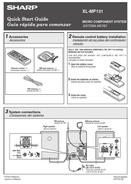
“ ” will appear when an FM broadcast is in stereo. Para recibir una transmisión de FM en estéreo: Pulse el botón TUNER (BAND) para que se visualice el indicador “ST”.
Podrá colocar los discos en las bandejas 2 - 5 siguiendo los pasos 2 - 4.
6 Press the / button to start playback.
Pulse el botón / para iniciar la reproducción.
1 Open the battery cover.
Abra la cubierta de las pilas.
2 Insert the batteries as shown.
Inserte las pilas como se muestra.
3 Close the cover.
Cierre la cubierta.
1 Accessories Accesorios
Remote control × 1 Controlador remoto × 1
AM loop antenna × 1 Antena de cuadro de AM × 1
FM antenna × 1 Antena de FM × 1
XL-MP131
导航系统131手册说明书
AAccessing the Address Book List (75)Add to Today’s Destinations......40, 44 Adding Destinations to the List.. (40)Address..............................21, 22, 76 Address Book .....................21, 41, 75 Address Book PIN.. (79)Advanced (33)Auto Daylight Saving Time (92)Auto Service (32)Auto Time Zone by GPS (92)Avoid Streets (63)BBack to Current Route (64)Banking (32)Basic Settings (91)Breadcrumbs.......................18, 58, 89 Brightness.. (72)By Address (22)By Address Book (41)By Go Home (42)By Intersection (26)By Map Input (36)By Places (31)By Previous Destinations (39)By Today’s Destinations (40)C Calculator (70)Calendar.................................. 17, 68CANCEL button (10)Cancel Current Route (64)Category.................................. 31, 77CD Voice Commands (127)Change Method (45)Change Routing Method........... 45, 63Change State............................ 22, 27Changing the DVD (101)Changing the Route (61)Changing the Routing Method (45)Changing Your Destination (64)City................................... 22, 27, 37City Vicinity (34)Climate Control Commands (125)Clock Adjustment (92)Color (93)Community (32)Continental USA (38)Contrast (74)Convert(Unit) (70)Correct Vehicle Position (90)Coverage Areas (102)Current Location...................... 19, 59Current Position....................... 36, 76Current Street (6)Customer Assistance (99)DDatabase Limitations (98)Delete Previous Destination (80)Deleting Waypoints (63)Destination ........................ 21, 44, 50Destination Icon (54)Destination Map (46)Detailed Coverage Areas ...... 102, 106Detour (63)Direct Route (45)Direction List (50)Display (73)Driving to Your Destination (44)EEasy Route (45)Edit Avoid Area (86)Edit Waypoint Search Area (88)Edit/Delete Address (78)Editing Today’s Destination List (40)Emergency (32)Entering a Destination (21)Entering Address Book (76)Entering the Security Code (94)131Entering the Street Number (26)Entering Your Schedule (69)Error Message (118)Exit Info (51)FFind Place Commands (124)Frequently Asked Questions (111)GGetting Started (10)Global Commands (122)Glossary (119)Go Home..................................21, 42 Go Home PIN...........................42, 80 Going Off the Route (58)GPS Initialization (95)Guidance Mode (89)Guidance Prompts.....................47, 74 Guidance Screen.. (49)HHome Address (78)Hotel/Motel (Lodging) (32)IIcon Bar (56)INFO button ............................ 10, 66 Information (66)Information Screen VoiceCommands (127)Intersection.............................. 21, 26J Joystick (11)KKey to Zagat Ratings (71)Keyboard Layout (91)LLandmark Icons (54)Leisure (32)Lodging (Hotel/Motel) (32)MMap Color (93)Map Coverage (102)Map Input................................ 21, 36Map Legend....................... 18, 48, 68Map Matching (95)Map Orientation (53)Map Scale (52)Map Screen........................ 18, 46, 48MAP/GUIDE button................. 10, 49Maximize Freeways (45)MENU button .......................... 10, 21Menu Color (93)Message (69)Microphone (12)Minimize Freeways (45)Minimize Toll Roads (45)NName ................................ 31, 35, 76NAVI BACK button (12)NAVI Talk button (12)Navigation Display Commands (123)Navigation General Commands (122)OOff-road Tracking .................... 58, 89On-Screen Commands (129)On-Screen Commands Assist (129)On-Screen Keyboard (15)132PPC Card (101)Personal Information (75)Phone Number....................31, 35, 77 PIN Number.. (79)Place Name ..............................33, 35 Place Name by Keyword.. (33)Places.................................21, 31, 77 Previous Destinations....21, 39, 77, 80 RRadio Voice Commands (126)Read List..................................32, 68 Recalculation. (81)Reporting Errors (99)Rerouting (81)Restaurant (32)Routing & Guidance (81)Routing Method (45)SSave Current (59)Schedule (69)Schedule List (69)Screen............................................11Search Waypoint on Route.. (61)Security Code (94)Selecting the City..................... 22, 27Selecting the State or Province.. 22, 27Selecting the Street................... 24, 29SET UP button (11)Setup Screen (first) Commands (128)Shopping (33)Show Icons on the Map (54)Sort by Distance to Travel (33)Split Screen Guidance (51)State.................................. 22, 27, 37 Street....................................... 24, 29System Controls (10)System Function Diagram (20)System Information (91)System Initialization (94)System Limitations (96)System Set-up (72)System Start-up (16)TTemperature Voice Commands (126)Time Adjustment (92)Title (69)Today’s Destination List (40)Today’s Destinations................ 21, 40 Travel.. (33)Trip Computer (66)Troubleshooting (118)UUnit Conversion (70)Units (mile or km) (91)Unverified Area Routing........... 82, 83Unverified streets (7)Update DVD (100)User Name (80)Using the Voice Control System (13)VVehicle (89)Verified streets (7)View Routes (45)Voice (91)Voice Command Help (67)Voice Command Index (122)Voice Control Basics (12)Voice Recognition Feedback (91)Voice Recognition, Improving (13)Volume (72)WWaypoints ............................... 61, 88Route ...........................44, 47, 58, 61133ZZOOM buttons (11)134。
RealWear HMT-1用户手册说明书
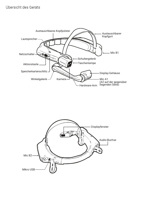
Übersicht des GerätsAufladen des HMT-11. S chließen Sie das USB-C-Ladekabel wiedargestellt an.2. S chließen Sie das Kabel wie abgebildetan das Ladegerät an und stecken Sie es ein.Der POWER-Knopf blinkt ROT, wenn das Gerätaufgeladen wird und GRÜN, wenn es vollständig aufgeladen ist.Micro-USB-Daten- undLadeanschluss unterder AbdeckungBenutzung des HMT-1 mit einem SchutzhelmUm die Schutzhelm-Clips zu erwerben, besuchen Sie .1. Nehmen Sie das Hinterkopfpolster und den oberen Kopfgurt ab.2. Haken Sie die Schutzhelm-Clips in das HMT-1-Band ein und rasten Sie diese ein.3. Schieben Sie die Clips in die Zubehör-Steckplätze des Schutzhelms; das HMT-1-Band sollte außerhalb der Kopfbefestigung des Schutzhelms sitzen.4. Setzen Sie den Schutzhelm auf und ziehen Sie ihn, falls nötig, fest, bis er bequem sitzt.5. Um das HMT-1 vom Schutzhelm zu entfernen, drücken Sie die Clip-Spitzen zusammen und schieben Sie den Clip aus den Schlitzen des Schutzhelms.I EQR Code für Konfiguration generieren11. B esuchen Sie auf Ihrem Computer oder Mobilgerät.2. Wählen Sie Konfiguration .3. F olgen Sie den Anweisungen, um Informationen einzugeben und einen QR-Code zu generieren.1. L aden Sie die RealWear Companion App aus dem Google Play oder Apple App Store herunter.2. S tarten Sie RealWear Companion auf Ihrem Smartphone.3. Wählen Sie Konfiguration .4. Wählen Sie Erstinstallation .5. F olgen Sie den Schritten in der App, um Informationen einzugeben und einen QR-Code zu generieren.Scannen Sie diesen Code mit Ihrem Smartphone, um RealWear Companion herunterzuladen.RealWear Companion App verwenden verwendenODERAufsetzen des HMT-1 235678910Halten Sie das Display nicht zu weit vom Auge entfernt. Führen Sie das Display so nahe wie möglichan das Auge, um eine optimale Sicht zu erhalten. Stellen Sie den Überkopf-Riemen so ein, dass der HTM-1 sich in der waagerechten Position etwas oberhalb Ihrer Augen befindet. Positionieren Sie dasSchulter- und Winkelgelenk in einer Z-Form, unterhalb der Sichthöhe, des linken oder rechten Auges.Als Augendominanz bezeichnet man die Tendenz dazu, visuelle Einflüsse des einen Auges über die des anderen zu bevorzugen. Die meisten Menschen haben eine Dominanz des rechten Auges; jedoch gibt es auch einen geringen Anteil der Bevölkerung, bei dem keine Dominanz eines Auges vorliegt.Am besten verwenden Sie Ihr dominantes Auge, wenn Sie auf das Display schauen.Entscheiden, welches Auge dominant ist1. Formen Sie mit Ihren Händen ein Dreieck. Strecken Sie dabei Ihre Arme aus.2. F okussieren Sie mit beiden (geöffneten) Augen e in beliebiges Objekt in der Ferne, sodass es sichin der Mitte des Dreiecks befindet.3. B ehalten Sie die Fokussierung auf das Objekt im Dreieck bei und schließen Sie das rechte Auge.Wenn sich das Objekt jetzt immer noch mittig im Dreieck befindet, ist Ihr linkes Auge dominant.4. B ehalten Sie die Fokussierung auf das Objekt im Dreieck bei und schließen Sie das linke Auge.Wenn sich das Objekt immer noch mittig im Dreieck befindet, ist Ihr rechtes Auge dominant.5. Ist das Objekt bei beiden Augen mittig im Dreieck, dann haben Sie eine neutrale Augendominanz.6.Wiederholen Sie den Test, um ihn zu bestätigen.Prüfen Sie Ihre Augendominanz245678910Halten Sie die Einschalttastefür 3 Sekunden gedrückt, um das Gerät einzuschalten.Drehen Sie die Kamera so nach oben/unten, dass Sie die optimale Sicht erhalten.Stellen Sie das Display-Gehäuse so ein, dass Sie alle vier Ecken des Displays sehen undblockieren Sie es dann mithilfe des Rings in der Position.Einschalten des HMT-1346789101. Der HMT-1 startet automatisch in den Konfigurationsmodus.2. Richten Sie die Kamera auf den QR Code, den Sie in Schritt 1 generiert haben.3. Der HMT-1 erkennt den QR Code und konfiguriert das Gerät.Der HMT -1 wird durch Sprache und Kopfbewegungengesteuert. Sagen Sie, was Sie auf dem Bildschirm sehen und bewegen Sie Ihren Kopf, um zu navigieren. Wenn Sie nicht weiterkommen, sagen Sie Hilfe anzeigen . Sagen Sie, was Sie sehen568910Scannen Sie den QR Code des HMT-14578910Hinweis: Sobald das Gerät mit dem WLAN verbunden ist, kann eine Aktualisierung des RealWear Device Agent auftreten.Hinweis: Um die Sprache zu ändern, drücken Sie die Funktionstaste an der Seite des HMT -1 und halten Sie sie gedrückt. Die Sprachauswahl wird automatisch wechseln. Lassen Sie die Taste los, wenn die von Ihnen gewünschte Sprache ausgewählt ist.。