毕业设计说明书中英文摘要范本--南京理工大学
080601545 谢裕鹏 外文资料翻译

南京理工大学紫金学院毕业设计(论文)外文资料翻译系:计算机系专业:计算机科学与技术姓名:谢裕鹏学号: 080601545外文出处:Pankaj Jalote. JSP in Practice(用外文写)Process for Executing SoftwareProjects at Infosys[Z]. AddisonWedsley Longman, Inc, 2009附件:1.外文资料翻译译文;2.外文原文。
注:请将该封面与附件装订成册。
附件1:外文资料翻译译文Overview of JSP TechnologyJSP provides the following benefits over servlets alone:A number of years ago, Marty was invited to attend a small 20-person industry roundtable discussion on software technology. Sitting in the seat next to Marty was James Gosling, inventor of the Java programming language. Sitting several seats away was a high-level manager from a very large software company in Redmond, Washington. During the discussion, the moderator brought up the subject of Jini, which at that time was a new Java technology. The moderator asked the manager what he thought of it, and the manager responded that it was too early to tell, but that it seemed to be an excellent idea. He went on to say that they would keep an eye on it, and if it seemed to be catching on, they would follow his company's usual "embrace and extend" strategy. At this point, Gosling lightheartedly interjected "You mean disgrace and distend."Now, the grievance that Gosling was airing was that he felt that this company would take technology from other companies and suborn it for their own purposes. But guess what? The shoe is on the other foot here. The Java community did not invent the idea of designing pages as a mixture of static HTML and dynamic code marked with special tags. For example, ColdFusion did it years earlier. Even ASP (a product from the very software company of the aforementioned manager) popularized this approach before JSP came along and decided to jump on the bandwagon. In fact, JSP not only adopted the general idea, it even used many of the same special tags as ASP did.So, the question becomes: why use JSP instead of one of these other technologies? Our first response is that we are not arguing that everyone should. Several of those other technologies are quite good and are reasonableoptions in some situations. In other situations, however, JSP is clearly better. Here are a few of the reasons..NET is well-designed technology from Microsoft. is the part that directly competes with servlets and JSP. The advantages of JSP are twofold.First, JSP is portable to multiple operating systems and Web servers; you aren't locked into deploying on Windows and IIS. Although the core .NET platform runs on a few non-Windows platforms, the ASP part does not. You cannot expect to deploy serious applications on multiple servers and operating systems. For some applications, this difference does not matter. For others, it matters greatly.Second, for some applications the choice of the underlying language matters greatly. For example, although .NET's C# language is very well designed and is similar to Java, fewer programmers are familiar with either the core C# syntax or the many auxiliary libraries. In addition, many developers still use the original version of ASP. With this version, JSP has a clear advantage for the dynamic code. With JSP, the dynamic part is written in Java, not VBScript or another ASP-specific language, so JSP is more powerful and better suited to complex applications that require reusable components.You could make the same argument when comparing JSP to the previous version of ColdFusion; with JSP you can use Java for the "real code" and are not tied to a particular server product. However, the current release of ColdFusion is within the context of a J2EE server, allowing developers to easily mix ColdFusion and servlet/JSP code.附件2:外文原文(复印件)JSP技术概述JSP提供下述好处:许多年前,Marty受到邀请,参加一个有关软件技术的小型(20个人)研讨会.做在Marty旁边的人是James Gosling--- Java编程语言的发明者。
毕业设计说明书中英文摘要范本--南京理工大学

毕业设计说明书(论文)外文摘要
TitleThree-dimensionalModeling of the Computer Case
Abstract
As scientific technologies and living conditions advance, more and more people use computer to socialize, shop online, and stay tuned to news events. Computers have greatly enriched people’s lives. As an essential component of an operating desktop computer, the computer case not only carries other important components of the computer, but also helps the computer ventilate as well as blocking radiations from reaching the users. This paper discusses the sheet metal forming processes and the calculation of the key process parameters of the computer case as a sheet metal product.By usingSolidWorkssoftware and relevant information regarding sheet metal and 3D modeling, the project designs and assembles case parts on a 3D platform under the premise of ensuring the functionality of the case. The engineering drawings of the design are also produced.
毕业设计中英文翻译【范本模板】
英文The road (highway)The road is one kind of linear construction used for travel。
It is made of the roadbed,the road surface, the bridge, the culvert and the tunnel. In addition, it also has the crossing of lines, the protective project and the traffic engineering and the route facility。
The roadbed is the base of road surface, road shoulder,side slope, side ditch foundations. It is stone material structure, which is designed according to route's plane position .The roadbed, as the base of travel, must guarantee that it has the enough intensity and the stability that can prevent the water and other natural disaster from corroding.The road surface is the surface of road. It is single or complex structure built with mixture。
The road surface require being smooth,having enough intensity,good stability and anti—slippery function. The quality of road surface directly affects the safe, comfort and the traffic。
计算机专业毕业设计说明书外文翻译(中英对照)
Talking about security loopholesRichard S. Kraus reference to the core network security business objective is to protect the sustainability of the system and data security, This two of the main threats come from the worm outbreaks, hacking attacks, denial of service attacks, Trojan horse. Worms, hacker attacks problems and loopholes closely linked to, if there is major security loopholes have emerged, the entire Internet will be faced with a major challenge. While traditional Trojan and little security loopholes, but recently many Trojan are clever use of the IE loophole let you browse the website at unknowingly were on the move.Security loopholes in the definition of a lot, I have here is a popular saying: can be used to stem the "thought" can not do, and are safety-related deficiencies. This shortcoming can be a matter of design, code realization of the problem.Different perspective of security loo phole sIn the classification of a specific procedure is safe from the many loopholes in classification.1. Classification from the user groups:● Public loopholes in the software category. If the loopholes in Windows, IEloophole, and so on.● specialized software loophole. If Oracle loopholes, Apach e, etc. loopholes.2. Data from the perspective include :● could not reasonably be read and read data, including the memory of thedata, documents the data, Users input data, the data in the database, network,data transmission and so on.● designa ted can be written into the designated places (including the localpaper, memory, databases, etc.)● Input data can be implemented (including native implementation,according to Shell code execution, by SQL code execution, etc.)3. From the point of view of the scope of the role are :● Remote loopholes, an attacker could use the network and directly throughthe loopholes in the attack. Such loopholes great harm, an attacker can createa loophole through other people's computers operate. Such loopholes and caneasily lead to worm attacks on Windows.● Local loopholes, the attacker must have the machine premise accesspermissions can be launched to attack the loopholes. Typical of the local authority to upgrade loopholes, loopholes in the Unix system are widespread, allow ordinary users to access the highest administrator privileges.4. Trigger conditions from the point of view can be divided into:● Initiative trigger loopholes, an attacker can take the initiative to use the loopholes in the attack, If direct access to computers.● Passive trigger loopholes must be computer operators can be carried out attacks with the use of the loophole. For example, the attacker made to a mail administrator, with a special jpg image files, if the administrator to open image files will lead to a picture of the software loophole was triggered, thereby system attacks, but if managers do not look at the pictures will not be affected by attacks.5. On an operational perspective can be divided into:● File opera tion type, mainly for the operation of the target file path can be controlled (e.g., parameters, configuration files, environment variables, the symbolic link HEC), this may lead to the following two questions: ◇Content can be written into control, the contents of the documents can be forged. Upgrading or authority to directly alter the important data (such as revising the deposit and lending data), this has many loopholes. If history Oracle TNS LOG document can be designated loopholes, could lead to any person may control the operation of the Oracle computer services;◇information content can be output Print content has been contained to a screen to record readable log files can be generated by the core users reading papers, Such loopholes in the history of the Unix system crontab subsystem seen many times, ordinary users can read the shadow ofprotected documents;● Memory coverage, mainly for memory modules can be specified, writecontent may designate such persons will be able to attack to enforce the code (buffer overflow, format string loopholes, PTrace loopholes, Windows 2000 history of the hardware debugging registers users can write loopholes), or directly alter the memory of secrets data.● logic errors, such wide gaps exist, but very few changes, so it is difficult todiscern, can be broken down as follows : ◇loopholes competitive conditions (usually for the design, typical of Ptrace loopholes, The existence of widespread document timing of competition) ◇wrong tactic, usually in design. If the history of the FreeBSD Smart IO loopholes. ◇Algorithm (usually code or design to achieve), If the history of Microsoft Windows 95/98 sharing password can easily access loopholes. ◇Imperfections of the design, such as TCP / IP protocol of the three-step handshake SYN FLOOD led to a denial of service attack. ◇realize the mistakes (usually no problem for the design, but the presence of coding logic wrong, If history betting system pseudo-random algorithm)● External orders, Typical of external commands can be controlled (via the PATH variable, SHELL importation of special characters, etc.) and SQL injection issues.6. From time series can be divided into:● has long found loopholes: manufacturers already issued a patch or repairmethods many people know already. Such loopholes are usually a lot of people have had to repair macro perspective harm rather small.● recently discovered loophole: manufacturers just made patch or repairmethods, the people still do not know more. Compared to greater danger loopholes, if the worm appeared fool or the use of procedures, so will result in a large number of systems have been attacked.● 0day: not open the loophole in the private transactions. Usually such loopholes to the public will not have any impact, but it will allow an attacker to the targetby aiming precision attacks, harm is very great.Different perspective on the use of the loopholesIf a defect should not be used to stem the "original" can not do what the (safety-related), one would not be called security vulnerability, security loopholes and gaps inevitably closely linked to use.Perspective use of the loopholes is:● Data Perspective: visit had not visited the data, including reading and writing.This is usually an attacker's core purpose, but can cause very serious disaster (such as banking data can be written).● Competence Perspective: Major Powers to bypass or p ermissions. Permissionsare usually in order to obtain the desired data manipulation capabilities.● Usability perspective: access to certain services on the system of controlauthority, this may lead to some important services to stop attacks and lead to a denial of service attack.● Authentication bypass: usually use certification system and the loopholes willnot authorize to access. Authentication is usually bypassed for permissions or direct data access services.● Code execution perspective: mainly procedures for the importation of thecontents as to implement the code, obtain remote system access permissions or local system of higher authority. This angle is SQL injection, memory type games pointer loopholes (buffer overflow, format string, Plastic overflow etc.), the main driving. This angle is usually bypassing the authentication system, permissions, and data preparation for the reading.Loopholes explore methods mustFirst remove security vulnerabilities in software BUG in a subset, all software testing tools have security loopholes to explore practical. Now that the "hackers" used to explore the various loopholes that there are means available to the model are:● fuzz testing (black box testing), by constructing procedures may lead toproblems of structural input data for automatic testing.● FOSS audit (White Box), now have a series of tools that can assist in thedetection of the safety procedures BUG. The most simple is your hands the latest version of the C language compiler.● IDA anti-compilation of the audit (gray box testing), and above the sourceaudit are very similar. The only difference is that many times you can obtain software, but you can not get to the source code audit, But IDA is a very powerful anti-Series platform, let you based on the code (the source code is in fact equivalent) conducted a safety audit.● dynamic tracking, is the record of proceedings under different conditions andthe implementation of all security issues related to the operation (such as file operations), then sequence analysis of these operations if there are problems, it is competitive category loopholes found one of the major ways. Other tracking tainted spread also belongs to this category.● patch, the software manufacturers out of the question usually addressed in thepatch. By comparing the patch before and after the source document (or the anti-coding) to be aware of the specific details of loopholes.More tools with which both relate to a crucial point: Artificial need to find a comprehensive analysis of the flow path coverage. Analysis methods varied analysis and design documents, source code analysis, analysis of the anti-code compilation, dynamic debugging procedures.Grading loopholesloopholes in the inspection harm should close the loopholes and the use of the hazards related Often people are not aware of all the Buffer Overflow Vulnerability loopholes are high-risk. A long-distance loophole example and better delineation:●R emote access can be an OS, application procedures, version information.●open unnecessary or dangerous in the service, remote access to sensitiveinformation systems.● Remote can be restricted for the documents, data reading.●remotely important or res tricted documents, data reading.● may be limited for long-range document, data revisions.● Remote can be restricted for important documents, data changes.● Remote can be conducted without limitation in the important documents, datachanges, or for general service denial of service attacks.● Remotely as a normal user or executing orders for system and network-leveldenial of service attacks.● may be remote management of user identities to the enforcement of the order(limited, it is not easy to use).● can be remote management of user identities to the enforcement of the order(not restricted, accessible).Almost all local loopholes lead to code execution, classified above the 10 points system for:●initiative remote trigger code execution (such a s IE loophole).● passive trigger remote code execution (such as Word gaps / charting softwareloopholes).DEMOa firewall segregation (peacekeeping operation only allows the Department of visits) networks were operating a Unix server; operating systems only root users and users may oracle landing operating system running Apache (nobody authority), Oracle (oracle user rights) services.An attacker's purpose is to amend the Oracle database table billing data. Its possible attacks steps:● 1. Access pea cekeeping operation of the network. Access to a peacekeepingoperation of the IP address in order to visit through the firewall to protect the UNIX server.● 2. Apache services using a Remote Buffer Overflow Vulnerability direct accessto a nobody's competence hell visit.● 3. Using a certain operating system suid procedure of the loophole to upgradetheir competence to root privileges.● 4. Oracle sysdba landing into the database (local landing without a password).● 5. Revised target table data.Over five down for process analysis:●Step 1: Authentication bypass●Step 2: Remote loopholes code execution (native), Authentication bypassing ● Step 3: permissions, authentication bypass● Step 4: Authentication bypass● Step 5: write data安全漏洞杂谈Richard S. Kraus 网络安全的核心目标是保障业务系统的可持续性和数据的安全性,而这两点的主要威胁来自于蠕虫的暴发、黑客的攻击、拒绝服务攻击、木马。
毕业设计说明书中英文摘要
湖南大学毕业设计 第 I 页X4市给水工程初步设计摘 要本设计的主要内容包括:取水构筑物设计;净水厂设计;输配水管网设计;工程总概算与制水成本分析四部分。
经用水量计算知,新水厂近期供水规模为5.4万3/m d ,远期为11万3/m d ,以地表水为水源。
取水工程由菱形箱式取水头部、自流管以及取水泵房组成。
取水泵房内径16.5m ,近期1台30019S 型水泵(Q=612-9353/m h ,H=22-14m ,N =103kw,n=970r/min )和2台50022S A 型水泵(其中1台为备用泵)(Q=1400-20203/m h ,H=20-14m ,N =185kW,n=970r/min )。
远期将30019S 型水泵换成50022S A 型水泵,并再增设一台50022S A 型水泵,即3台50022S A 工作,1台50022S A 备用。
净水工程常规工艺采用折板絮凝池、平流沉淀池、V 型滤池、液氯消毒工艺,絮凝剂选用碱式氯化铝。
絮凝池与沉淀池合建,采用2组,每组设计水量为32.7/q m d =万。
絮凝池设计絮凝时间为19.9min ,絮凝池尺寸:15.68.20 3.50L B H m m m ⨯⨯=⨯⨯,有效水深为3.20m 。
平流沉淀池设计停留时间为2h ,尺寸:868.2 3.6L B H m m m ⨯⨯=⨯⨯,有效水深:3.3H m =,池内平均水平流速:11/v mm s =,弗劳德数:51.1810Fr -=⨯(在510-~410-范围内),雷诺数:Re 14880=(一般为4000-15000)。
V 型滤池设两组,每组设计水量为32.7/q m d =万,共四格,单格池宽 3.0B m =,池长10.5L m =,面积为422m 。
设计滤速采用9/v m h =,强制滤速v '=11/m h 。
滤池采用单层石英砂均粒滤料,有效粒径在0.95~1.35m ,不均匀系数80 1.30K =。
毕业设计(论文)外文资料翻译
南京理工大学紫金学院毕业设计(论文)外文资料翻译系:机械工程系专业:机械工程及自动化姓名:徐华俊学号:100104348外文出处:WASTE FOOD DISPOSAL SYSTEM(3)(用外文写)附件:1.外文资料翻译译文;2.外文原文。
指导教师评语:该生翻译了一篇有关《废弃食物处理系统》的论文,论文内容跟课题的研究领域相关,在将来的课题设计中可以借鉴。
译文语句基本通顺,专业术语正确,标点符号运用无误。
说明该生具备一定的英语水平和翻译能力。
但文中仍有部分语句组织得不够完善,可以进一步修改。
签名:年月日注:请将该封面与附件装订成册。
附件1:外文资料翻译译文垃圾食物处理系统(3)打开功率继电器32的驱动,关闭与其相连的常闭开关118,从而消除了在此之前被施加到定时器单元40的控制终端146的触发信号,并且需要注意的是,功率继电器30的电源开关108供应了一个类似的功能,如本文所述的,启动系统10每天第一次激活功率继电器30的时候,这个功能中断了定时器单元40的控制终端146,即先前追踪的触发信号电路,如本文所述。
进一步,在与功率继电器32相连的开关被关闭的时候,它的驱动被触发的结果是非常明显的,断开常开继电器开关119,为高流量水阀22的电磁阀80建立了一个到地面的备用路径,也就是可以追踪到电源线200;通过导线202;电磁阀80;导线204;导线416和现在被断开的功率继电器32的闭合开关119到地面,如此一来就能明显并且很方便的注意到,与功率继电器30相连的开关109执行同样的功能,通过一个完全可追踪的功率继电器30,而不是功率继电器32,使功率继电器30处于启动状态,所以在任何时期,控制单元12的电动机46可在任意一个方向操作(这取决于功率继电器30或功率继电器32处于激活状态),电磁阀80也将保持通电,来保持高流量水阀22在该段时期内处于闭合状态,这样的话,水流将会在需要大幅率的时候流通,通过管道76和78流到控制单元12,这个控制单元12的机构52正积极粉碎积累废料,并且已经积累或正在采用,接着顺着水流冲到下水道或者通过类似单元12的出口58.你将会很方便的观察到电磁阀74保持通电,并且在控制单元12积极运作期间,低流量水阀20也保持闭合,并且应当在任何特定安装情况下,把阀22的流通能力考虑在内。
校级优秀毕业设计论文-南京理工大学理学院【范本模板】
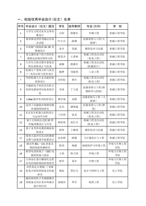
教育实验学院
96
多通道电能计量与充电过程实时监控系统设计
董文杰
张合
机械工程及自动化(实院)
教育实验学院
97
面向监控视频的行人跟踪算法设计与实现
邵晴薇
赵春霞
计算机科学与技术(实院)
教育实验学院
98
小型化定量相位显微成像仪
张佳琳
陈钱
光电信息工程(实院)
教育实验学院
99
宽带滤波电路中可重构限带结构的设计与分析
陈锦成
韩玉阁
热能与动力工程
能源与动力工程学院
54
重庆市某县人民医院主体(A区)空调系统设计
苏杭
曹琳
建筑环境与设备工程
能源与动力工程学院
55
基于多体系统传递矩阵法的直升机武器系统动力学建模与仿真
王勋
芮筱亭
武器系统与发射工程
能源与动力工程学院
56
氧化铒选择性辐射器光谱辐射特性研究
赵斌
谭洪
热能与动力工程
能源与动力工程学院
73
基于纹理提取与优化的图像矢量化方法
杨阳
李建良
数学与应用数学
理学院
74
分子动力学模拟研究石墨烯材料缺陷演化机理
夏骏
尹晓春
工程力学
理学院
75
声波在颗粒链中的非线性传播特性
矫滕菲
黄德财
应用物理学
理学院
76
ZrTe5,HfTe5的单晶生长及输运性质研究
康宝蕾
吴海平
应用物理学
理学院
77
多个专家数据的集成方法研究
经济管理学院
50
商品评论信息的观点抽取及其分类研究
毕业设计(论文)外文资料翻译【范本模板】
南京理工大学紫金学院毕业设计(论文)外文资料翻译系:机械系专业:车辆工程专业姓名:宋磊春学号:070102234外文出处:EDU_E_CAT_VBA_FF_V5R9(用外文写)附件:1。
外文资料翻译译文;2.外文原文.附件1:外文资料翻译译文CATIA V5 的自动化CATIA V5的自动化和脚本:在NT 和Unix上:脚本允许你用宏指令以非常简单的方式计划CATIA。
CATIA 使用在MS –VBScript中(V5.x中在NT和UNIX3。
0 )的共用部分来使得在两个平台上运行相同的宏。
在NT 平台上:自动化允许CATIA像Word/Excel或者Visual Basic程序那样与其他外用分享目标。
ATIA 能使用Word/Excel对象就像Word/Excel能使用CATIA 对象。
在Unix 平台上:CATIA将来的版本将允许从Java分享它的对象。
这将提供在Unix 和NT 之间的一个完美兼容。
CATIA V5 自动化:介绍(仅限NT)自动化允许在几个进程之间的联系:CATIA V5 在NT 上:接口COM:Visual Basic 脚本(对宏来说),Visual Basic 为应用(适合前:Word/Excel ),Visual Basic。
COM(零部件目标模型)是“微软“标准于几个应用程序之间的共享对象。
Automation 是一种“微软“技术,它使用一种解释环境中的COM对象。
ActiveX 组成部分是“微软“标准于几个应用程序之间的共享对象,即使在解释环境里。
OLE(对象的链接与嵌入)意思是资料可以在一个其他应用OLE的资料里连结并且可以被编辑的方法(在适当的位置编辑).在VBScript,VBA和Visual Basic之间的差别:Visual Basic(VB)是全部的版本。
它能产生独立的计划,它也能建立ActiveX 和服务器。
它可以被编辑。
VB中提供了一个补充文件名为“在线丛书“(VB的5。
南京理工大学毕业论文格式
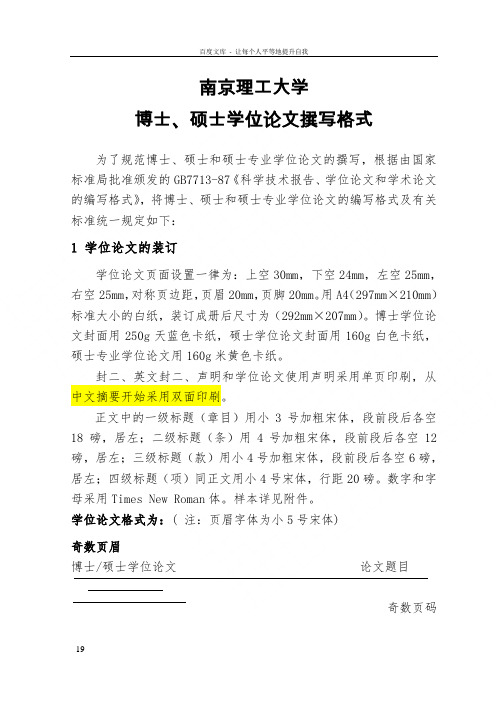
南京理工大学博士、硕士学位论文撰写格式为了规范博士、硕士和硕士专业学位论文的撰写,根据由国家标准局批准颁发的GB7713-87《科学技术报告、学位论文和学术论文的编写格式》,将博士、硕士和硕士专业学位论文的编写格式及有关标准统一规定如下:1 学位论文的装订学位论文页面设置一律为:上空30mm,下空24mm,左空25mm,右空25mm,对称页边距,页眉20mm,页脚20mm。
用A4(297mm×210mm)标准大小的白纸,装订成册后尺寸为(292mm×207mm)。
博士学位论文封面用250g天蓝色卡纸,硕士学位论文封面用160g白色卡纸,硕士专业学位论文用160g米黄色卡纸。
封二、英文封二、声明和学位论文使用声明采用单页印刷,从中文摘要开始采用双面印刷。
正文中的一级标题(章目)用小3号加粗宋体,段前段后各空18磅,居左;二级标题(条)用4号加粗宋体,段前段后各空12磅,居左;三级标题(款)用小4号加粗宋体,段前段后各空6磅,居左;四级标题(项)同正文用小4号宋体,行距20磅。
数字和字母采用Times New Roman体。
样本详见附件。
学位论文格式为:( 注:页眉字体为小5号宋体)奇数页眉博士/硕士学位论文论文题目奇数页码偶数页眉章节号和名博士/硕士学位论文偶数页码2 学位论文前置部分封面封面按统一的学位论文封面的内容和格式填写。
(见附件,注:密级部分如:秘密、机密或绝密必须填,其余可不填。
密级后面★作标志,★后注明保密期限。
)书脊要注明学位论文题名及学位授予单位名称。
封二学位论文的封二可作为封面标识项目的延续,内容包括学位论文级别、题目、作者、指导教师、作者单位、出版时间等。
该页置于封面下面,包括中英文版,中文在前,英文在后。
字体和字号以封面为准。
见附件和附件。
声明另页起,用附件,对其内容不得作任何改动。
该声明置于封二之后,中文摘要之前。
摘要摘要是学位论文内容的不加注释和评论的简短陈述,说明研究工作的目的、实验方法、实验结果和最终结论等。
毕业设计的论文中英翻译
Anti-Aircraft Fire Control and the Development of IntegratedSystems at SperryT he dawn of the electrical age brought new types of control systems. Able to transmit data between distributed components and effect action at a distance, these systems employed feedback devices as well as human beings to close control loops at every level. By the time theories of feedback and stability began to become practical for engineers in the 1930s a tradition of remote and automatic control engineering had developed that built distributed control systems with centralized information processors. These two strands of technology, control theory and control systems, came together to produce the large-scale integrated systems typical of World War II and after.Elmer Ambrose Sperry (I860-1930) and the company he founded, the Sperry Gyroscope Company, led the engineering of control systems between 1910 and 1940. Sperry and his engineers built distributed data transmission systems that laid the foundations of today‟s command and control systems. Sperry‟s fire control systems included more than governors or stabilizers; they consisted of distributed sensors, data transmitters, central processors, and outputs that drove machinery. This article tells the story of Sperry‟s involvement in anti-aircraft fire control between the world wars and shows how an industrial firm conceived of control systems before the common use of control theory. In the 1930s the task of fire control became progressively more automated, as Sperry engineers gradually replaced human operators with automatic devices. Feedback, human interface, and system integration posed challenging problems for fire control engineers during this period. By the end of the decade these problems would become critical as the country struggled to build up its technology to meet the demands of an impending war.Anti-Aircraft Artillery Fire ControlBefore World War I, developments in ship design, guns, and armor drove the need for improved fire control on Navy ships. By 1920, similar forces were at work in the air: wartime experiences and postwar developments in aerial bombing created the need for sophisticated fire control for anti-aircraft artillery. Shooting an airplane out of the sky is essentially a problem of “leading” the target. As aircraft developed rapidly in the twenties, their increased speed and altitude rapidly pushed the task of computing the lead out of the range of human reaction and calculation. Fire control equipment for anti-aircraft guns was a means of technologically aiding human operators to accomplish a task beyond their natural capabilities.During the first world war, anti-aircraft fire control had undergone some preliminary development. Elmer Sperry, as chairman of the Aviation Committee of the Naval Consulting Board, developed two instruments for this problem: a goniometer,a range-finder, and a pretelemeter, a fire director or calculator. Neither, however, was widely used in the field.When the war ended in I918 the Army undertook virtually no new development in anti-aircraft fire control for five to seven years. In the mid-1920s however, the Army began to develop individual components for anti-aircraft equipment including stereoscopic height-finders, searchlights, and sound location equipment. The Sperry Company was involved in the latter two efforts. About this time Maj. Thomas Wilson, at the Frankford Arsenal in Philadelphia, began developing a central computer for firecontrol data, loosely based on the system of “director firing” that had developed in naval gunn ery. Wilson‟s device resembled earlier fire control calculators, accepting data as input from sensing components, performing calculations to predict the future location of the target, and producing direction information to the guns.Integration and Data TransmissionStill, the components of an anti-aircraft battery remained independent, tied together only by telephone. As Preston R. Bassett, chief engineer and later president of the Sperry Company, recalled, “no sooner, however, did the components get to the point of functioning satisfactorily within themselves, than the problem of properly transmitting the information from one to the other came to be of prime importance.”Tactical and terrain considerations often required that different fire control elements be separated by up to several hundred feet. Observers telephoned their data to an officer, who manually entered it into the central computer, read off the results, and telephoned them to the gun installations. This communication system introduced both a time delay and the opportunity for error. The components needed tighter integration, and such a system required automatic data communications.In the 1920s the Sperry Gyroscope Company led the field in data communications. Its experience came from Elmer Spe rry‟s most successful invention, a true-north seeking gyro for ships. A significant feature of the Sperry Gyrocompass was its ability to transmit heading data from a single central gyro to repeaters located at a number of locations around the ship. The repeaters, essentially follow-up servos, connected to another follow-up, which tracked the motion of the gyro without interference. These data transmitters had attracted the interest of the Navy, which needed a stable heading reference and a system of data communication for its own fire control problems. In 1916, Sperry built a fire control system for the Navy which, although it placed minimal emphasis on automatic computing, was a sophisticated distributed data system. By 1920 Sperry had installed these systems on a number of US. battleships.Because of the Sperry Company‟s experience with fire control in the Navy, as well as Elmer Sperry‟s earlier work with the goniometer and the pretelemeter, the Army approached the company for help with data transmission for anti-aircraft fire control. To Elmer Sperry, it looked like an easy problem: the calculations resembled those in a naval application, but the physical platform, unlike a ship at sea, anchored to the ground. Sperry engineers visited Wilson at the Frankford Arsenal in 1925, and Elmer Sperry followed up with a letter expressing his interest in working on the problem. He stressed his company‟s experience with naval problems, as well as its recent developments in bombsights, “work from the other end of the pro position.” Bombsights had to incorporate numerous parameters of wind, groundspeed, airspeed, and ballistics, so an anti-aircraft gun director was in some ways a reciprocal bombsight . In fact, part of the reason anti-aircraft fire control equipment worked at all was that it assumed attacking bombers had to fly straight and level to line up their bombsights. Elmer Sperry‟s interests were warmly received, and in I925 and 1926 the Sperry Company built two data transmission systems for the Army‟s gun directors.The original director built at Frankford was designated T-1, or the “Wilson Director.” The Army had purchased a Vickers director manufactured in England, but encouraged Wilson to design one thatcould be manufactured in this country Sperry‟s two data tran smission projects were to add automatic communications between the elements of both the Wilson and the Vickers systems (Vickers would eventually incorporate the Sperry system into its product). Wilson died in 1927, and the Sperry Company took over the entire director development from the Frankford Arsenal with a contract to build and deliver a director incorporating the best features of both the Wilson and Vickers systems. From 1927 to 193.5, Sperry undertook a small but intensive development program in anti-aircraft systems. The company financed its engineering internally, selling directors in small quantities to the Army, mostly for evaluation, for only the actual cost of production [S]. Of the nearly 10 models Sperry developed during this period, it never sold more than 12 of any model; the average order was five. The Sperry Company offset some development costs by sales to foreign govemments, especially Russia, with the Army‟s approval 191.The T-6 DirectorSperry‟s modified version of Wilson‟s director was designated T-4 in development. This model incorporated corrections for air density, super-elevation, and wind. Assembled and tested at Frankford in the fall of 1928, it had problems with backlash and reliability in its predicting mechanisms. Still, the Army found the T-4 promising and after testing returned it to Sperry for modification. The company changed the design for simpler manufacture, eliminated two operators, and improved reliability. In 1930 Sperry returned with the T-6, which tested successfully. By the end of 1931, the Army had ordered 12 of the units. The T-6 was standardized by the Army as the M-2 director.Since the T-6 was the first anti-aircraft director to be put into production, as well as the first one the Army formally procured, it is instructive to examine its operation in detail. A technical memorandum dated 1930 explained the theory behind the T-6 calculations and how the equations were solved by the system. Although this publication lists no author, it probably was written by Earl W. Chafee, Sperry‟s director of fire control engineering. The director was a complex mechanical analog computer that connected four three-inch anti-aircraft guns and an altitude finder into an integratedsystem (see Fig. 1). Just as with Sperry‟s naval fire control system, the primary means of connection were “data transmitters,” similar to those that connected gyrocompasses to repeaters aboard ship.The director takes three primary inputs. Target altitude comes from a stereoscopic range finder. This device has two telescopes separated by a baseline of 12 feet; a single operator adjusts the angle between them to bring the two images into coincidence. Slant range, or the raw target distance, is then corrected to derive its altitude component. Two additional operators, each with a separate telescope, track the target, one for azimuth and one for elevation. Each sighting device has a data transmitter that measures angle or range and sends it to the computer. The computer receives these data and incorporates manual adjustments for wind velocity, wind direction, muzzle velocity, air density, and other factors. The computer calculates three variables: azimuth, elevation, and a setting for the fuze. The latter, manually set before loading, determines the time after firing at which the shell will explode. Shells are not intended to hit the target plane directly but rather to explode near it, scattering fragments to destroy it.The director performs two major calculations. First, pvediction models the motion of the target and extrapolates its position to some time in the future. Prediction corresponds to “leading” the target. Second, the ballistic calculation figures how to make the shell arrive at the desired point in space at the future time and explode, solving for the azimuth and elevation of the gun and the setting on the fuze. This calculation corresponds to the traditional artillery man‟s task of looking up data in a precalculated “firing table” and setting gun parameters accordingly. Ballistic calculation is simpler than prediction, so we will examine it first.The T-6 director solves the ballistic problem by directly mechanizing the traditional method, employing a “mechanical firing table.” Traditional firing tables printed on paper show solutions for a given angular height of the target, for a given horizontal range, and a number of other variables. The T-6 replaces the firing table with a Sperry ballistic cam.” A three-dimensionally machined cone shaped device, the ballistic cam or “pin follower” solves a pre-determined function. Two independent variables are input by the angular rotation of the cam and the longitudinal position of a pin that rests on top of the cam. As the pin moves up and down the length of the cam, and as the cam rotates, the height of the pin traces a function of two variables: the solution to the ballistics problem (or part of it). The T-6 director incorporates eight ballistic cams, each solving for a different component of the computation including superelevation, time of flight, wind correction, muzzle velocity. air density correction. Ballistic cams represented, in essence, the stored data of the mechanical computer. Later directors could be adapted to different guns simply by replacing the ballistic cams with a new set, machined according to different firing tables. The ballistic cams comprised a central component of Sperry‟s mechanical computing technology. The difficulty of their manufacture would prove a major limitation on the usefulness of Sperry directors.The T-6 director performed its other computational function, prediction, in an innovative way as well. Though the target came into the system in polar coordinates (azimuth, elevation, and range), targets usually flew a constant trajectory (it was assumed) in rectangular coordinates-i.e. straight andlevel. Thus, it was simpler to extrapolate to the future in rectangular coordinates than in the polar system. So the Sperry director projected the movement of the target onto a horizontal plane, derived the velocity from changes in position, added a fixed time multiplied by the velocity to determine a future position, and then converted the solution back into polar coordinates. This method became known as the “plan prediction method”because of the representation of the data on a flat “plan” as viewed from above; it was commonly used through World War II. In the plan prediction method, “the actual movement of the target is mechanically reproduced on a small scale within the Computer and the desired angles or speeds can be measured directly from the movements of these elements.”Together, the ballistic and prediction calculations form a feedback loop. Operators enter an estimated “time of flight” for the shell when they first begin tracking. The predictor uses this estimate to perform its initial calculation, which feeds into the ballistic stage. The output of the ballistics calculation then feeds back an updated time-of-flight estimate, which the predictor uses to refine the initial estimate. Thus “a cumulative cycle of correction brings the predicted future position of the target up to the point indicated by the actual future time of flight.”A square box about four feet on each side (see Fig. 2) the T-6 director was mounted on a pedestal on which it could rotate. Three crew would sit on seats and one or two would stand on a step mounted to the machine. The remainder of the crew stood on a fixed platform; they would have had to shuffle around as the unit rotated. This was probably not a problem, as the rotation angles were small. The direc tor‟s pedestal mounted on a trailer, on which data transmission cables and the range finder could be packed for transportation.We have seen that the T-6 computer took only three inputs, elevation, azimuth, and altitude (range), and yet it required nine operators. These nine did not include the operation of the range finder, which was considered a separate instrument, but only those operating the director itself. What did these nine men do?Human ServomechanismsTo the designers of the director, the operato rs functioned as “manual servomechanisms.”One specification for the machine required “minimum dependence on …human element.‟ The Sperry Company explained, “All operations must be made as mechanical and foolproof as possible; training requirements must visualize the conditions existent under rapid mobilization.” The lessons of World War I ring in this statement; even at the height of isolationism, with the country sliding into depression, design engineers understood the difficulty of raising large numbers of trained personnel in a national emergency. The designers not only thought the system should account for minimal training and high personnel turnover, they also considered the ability of operators to perform their duties under the stress of battle. Thus, nearly all the work for the crew was in a “follow-the-pointer”mode: each man concentrated on an instrument with two indicating dials, one the actual and one the desired value for a particular parameter. With a hand crank, he adjusted the parameter to match the two dials.Still, it seems curious that the T-6 director required so many men to perform this follow-the-pointer input. When the external rangefinder transmitted its data to the computer, it appeared on a dial and an operator had to follow the pointer to actually input the data into the computing mechanism. The machine did not explicitly calculate velocities. Rather, two operators (one for X and one for Y) adjusted variable-speed drives until their rate dials matched that of a constant-speed motor. When the prediction computation was complete, an operator had to feed the result into the ballistic calculation mechanism. Finally, when the entire calculation cycle was completed, another operator had to follow the pointer to transmit azimuth to the gun crew, who in turn had to match the train and elevation of the gun to the pointer indications.Human operators were the means of connecting “individual elements” into an integrated system. In one sense the men were impedance amplifiers, and hence quite similar to servomechanisms in other mechanical calculators of the time, especially Vannevar Bush‟s differential analyzer .The term “manual servomechanism”itself is an oxymoron: by the conventional definition, all servomechanisms are automatic. The very use of the term acknowledges the existence of an automatic technology that will eventually replace the manual method. With the T-6, this process was already underway. Though the director required nine operators, it had already eliminated two from the previous generation T-4. Servos replaced the operator who fed back superelevation data and the one who transmitted the fuze setting. Furthermore, in this early machine one man corresponded to one variable, and the machine‟s requirement for operators corresponded directly to the data flow of its computation. Thus the crew that operated the T-6 director was an exact reflection of the algorithm inside it.Why, then, were only two of the variables automated? This partial, almost hesitating automation indicates there was more to the human servo-motors than Sperry wanted to acknowledge. As much as the company touted “their duties are purely mechanical and little skill or judgment is required on the part of the operators,” men were still required to exercise some judgment, even if unconsciously. The data were noisy, and even an unskilled human eye could eliminate complications due to erroneous or corrupted data. The mechanisms themselves were rather delicate and erroneous input data, especially if it indicated conditions that were not physically possible, could lock up or damage the mechanisms. Theoperators performed as integrators in both senses of the term: they integrated different elements into a system.Later Sperry DirectorsWhen Elmer Sperry died in 1930, his engineers were at work on a newer generation director, the T-8. This machine was intended to be lighter and more portable than earlier models, as well as less expensive and “procurable in quantities in case of emergency.” The company still emphasized the need for unskilled men to operate the system in wartime, and their role as system integrators. The operators were “mechanical links in the apparatus, thereby making it possible to avoid mechanical complication which would be involved by the use of electrical or mechanical servo motors.” Still, army field experience with the T-6 had shown that servo-motors were a viable way to reduce the number of operators and improve reliability, so the requirements for the T-8 specified that wherever possible “electrical shall be used to reduce the number of operators to a minimum.” Thus the T-8 continued the process of automating fire control, and reduced the number of operators to four. Two men followed the target with telescopes, and only two were required for follow-the-pointer functions. The other follow-the-pointers had been replaced by follow-up servos fitted with magnetic brakes to eliminate hunting. Several experimental versions of the T-8 were built, and it was standardized by the Army as the M3 in 1934.Throughout the remain der of the …30s Sperry and the army fine-tuned the director system in the M3. Succeeding M3 models automated further, replacing the follow-the-pointers for target velocity with a velocity follow-up which employed a ball-and-disc integrator. The M4 series, standardized in 1939, was similar to the M3 but abandoned the constant altitude assumption and added an altitude predictor for gliding targets. The M7, standardized in 1941, was essentially similar to the M4 but added full power control to the guns for automatic pointing in elevation and azimuth. These later systems had eliminated errors. Automatic setters and loaders did not improve the situation because of reliability problems. At the start of World War II, the M7 was the primary anti-aircraft director available to the army.The M7 was a highly developed and integrated system, optimized for reliability and ease of operation and maintenance. As a mechanical computer, it was an elegant, if intricate, device, weighing 850 pounds and including about 11,000 parts. The design of the M7 capitalized on the strength of the Sperry Company: manufacturing of precision mechanisms, especially ballistic cams. By the time the U.S. entered the second world war, however, these capabilities were a scarce resource, especially for high volumes. Production of the M7 by Sperry and Ford Motor Company as subcontractor was a “real choke” and could not keep up with production of the 90mm guns, well into 1942. The army had also adopted an English system, known as the “Kerrison Director” or M5, which was less accurate than the M7 but easier to manufacture. Sperry redesigned the M5 for high-volume production in 1940, but passed in 1941.Conclusion: Human Beings as System IntegratorsThe Sperry directors we have examined here were transitional, experimental systems. Exactly for that reason, however, they allow us to peer inside the process of automation, to examine the displacement of human operators by servomechanisms while the process was still underway. Skilled asthe Sperry Company was at data transmission, it only gradually became comfortable with the automatic communication of data between subsystems. Sperry could brag about the low skill levels required of the operators of the machine, but in 1930 it was unwilling to remove them completely from the process. Men were the glue that held integrated systems together.As products, the Sperry Company‟s anti-aircraft gun directors were only partially successful. Still, we should judge a technological development program not only by the machines it produces but also by the knowledge it creates, and by how that knowledge contributes to future advances. Sperry‟s anti-aircraft directors of the 1930s were early examples of distributed control systems, technology that would assume critical importance in the following decades with the development of radar and digital computers. When building the more complex systems of later years, engineers at Bell Labs, MIT, and elsewhere would incorporate and build on the Sperry Company‟s experience,grappling with the engineering difficulties of feedback, control, and the augmentation of human capabilities by technological systems.在斯佩里防空炮火控和集成系统的发展电气时代的到来带来了新类型的控制系统。
毕业设计(论文)外文资料翻译(学生用)

南京理工大学紫金学院毕业设计(论文)外文资料翻译系:计算机专业:计算机科学与技术姓名:沈俊男学号: 060601239外文出处: E. Jimenez-Ruiz,R. Berlanga. The Management(用外文写)and Integration of Biomedical[M/OL].Castellon:Spanish Ministry of Education andScience project,2004[2005-09098]./ftp/cs/papers/0609/0609144.pdf附件: 1.外文资料翻译译文;2.外文原文。
注:请将该封面与附件装订成册。
附件1:外文资料翻译译文管理和集成的生物医学知识:应用于Health-e-Child项目摘要:这个Health-e-Child项目的目的是为欧洲儿科学发展集成保健平台。
为了实现一个关于儿童健康的综合观点,一个复杂的生物医学数据、信息和知识的整合是必需的。
本体论将用于正式定义这个领域的专业知识,将塑造医学知识管理系统的基础。
文中介绍了一种对生物医学知识的垂直整合的新颖的方法。
该方法将会主要使临床医生中心化,并使定义本体碎片成为可能,连接这些碎片(语义桥接器),丰富了本体碎片(观点)。
这个策略为规格和捕获的碎片,桥接器和观点概述了初步的例子证明从医院数据库、生物医学本体、生物医学公共数据库的生物医学信息的征收。
关键词:垂直的知识集成、近似查询、本体观点、语义桥接器1.1 医学数据集成问题数据来源的集成已经在数据库社区成为传统的研究课题。
一个综合数据库系统主要的目标是允许用户均匀的访问一个分布和一个异构数据库。
数据集成的关键因素是定义一个全局性的模式,但是值得指出的是,我们必须区分三种全局模式:数据库模式、概念模式和域本体模式。
首先介绍了数据类型的信息存储、本地查询;其二,概括了这些图式采用更富有表达力的数据模型,如统一建模语言(UML)(TAMBIS和SEMEDA都遵循这个模式)。
毕业设计说明书 (理工类专业学生用)

毕业设计说明书作者: 学号:学院:专业(方向):题目:指导者:(姓名) (专业技术职务)(姓名) (专业技术职务)评阅者:(姓名) (专业技术职务)年月声明我声明,本毕业设计说明书及其研究工作和所取得的成果是本人在导师的指导下独立完成的。
研究过程中利用的所有资料均已在参考文献中列出,其他人员或机构对本毕业设计工作做出的贡献也已在致谢部分说明。
本毕业设计说明书不涉及任何秘密,南京理工大学有权保存其电子和纸质文档,可以借阅或网上公布其部分或全部内容,可以向有关部门或机构送交并授权保存、借阅或网上公布其部分或全部内容。
学生签名:年月日指导教师签名:年月日第页本科毕业设计说明书目次1绪论 (1)1.1 课题研究背景及现状 (1)1.2 非晶合金的形成原理 (2)1.3 非晶合金材料的制备方法 (3)1.4非晶合金的性能和生物医用研究进展 (4)1.5 合金元素的添加对非晶合金的影响 (6)2 实验方法 (7)2.1试样制备 (7)2.2非晶合金的制备及非晶合金结构确定 (7)2.3实验所用仪器及步骤 (8)2.4试样表面成分分析 (9)3 实验数据分析 (10)3.1 XRD结构特征分析 (10)3.2在NaCl溶液下的电化学腐蚀测试 (11)3.3在PBS磷酸根缓冲液下的电化学腐蚀测试 (15)结论 (21)致谢 (22)参考文献 (23)本科毕业设计说明书第I 页第0 页本科毕业设计说明书1 绪论1.1 课题背景及研究的现状1.1.1 背景资料现存的固体材料种类众多,拥有许多不同的性能,按照其结构状态来划分,一般可分为晶体、准晶体、非晶体。
非晶材料分为:(1)传统玻璃;(2)非晶合金;(3)非晶半导体;(4)高分子聚合物。
非晶合金是非晶材料的四大分支之一,微观结构上所拥有的基本特征有:(1)长程无序,短程有序;(2) TEM衍射花样为弥散的晕环组成,TEM中可观察不到晶粒晶界、晶格缺陷等形成的衍衬反差;其径向分布函数(RDF)中出现清晰可见的第一峰和第二峰,而第三近邻以后几乎没有可分辨的峰,这和通常的晶态材料明显不同[2]。
南京理工大毕业证英文翻译模板

School (Seal): Chongqing No.11 Middle School (Seal) Chongqing Education Commission (Seal) Principal (Seal): Chen Qipeng (Signature) Made by Chongqing Education Commission June 20, 2006
Regular Senior High School of Chongqing
Diploma
Made by Chongqing Education Commission
Regular Senior High School of xx, male, 18 years old, a native of Chongqing, studied as a senior high school student in Class 1, Grade 2006 of our school from September 2003 to June 2006. Upon completion of
Nanjing University of Posts and Telecommunications
Diploma
Photo
Nanjing University of Posts and Telecommunications (Steel seal) xxxxx, male, born on October 8, 1987, majoring in Communication Engineering at the School of Telecommunication and Information Engineering of this University from September 2006 to July 2010, has been permitted to graduate upon completing all the courses specified by the four-year undergraduate teaching program with qualified scores. Electronic Registration No.: xxxxxxxx Student No.: xxxxx No.: xxxxxxx July 9, 2010 President: Yang Zhen (Signature)
毕业设计方案英文翻译资料(中文)

故障概率模型的数控车床摘要:领域的失效分析被计算机数字化控制<CNC)车床描述。
现场收集了为期两年的约80台数控车床的故障数据。
编码系统代码失效数据是制定和失效分析数据库成立的数控车床。
失败的位置和子系统,失效模式及原因进行了分析,以显示薄弱子系统的数控车床。
另外,故障的概率模型,分析了数控车床的模糊多准则综合评价。
作者关键词:数控车床;场失败;概率模型;模糊信息文章概述1.介绍2. CNC车床的概述3.收集和整理数据3.1. 收集数据3.2. 领域失效数据的有效性3.3. 数据核对和数据库4. 失效分析4.1. 对失败位置和子系统的频率分析4.2. 对失败形式的频率分析5.失败机率模型5.1. 方法学5.2. 分布倍之间连续的失败5.3. 修理时间的发行6.结论1.介绍在过去十年中,计算机数字化控制<CNC)车床已经越来越多地被引入到机械加工过程中。
由于其固有的灵活性很大,稳定的加工精度和高生产率,数控车床是能给用户巨大的利益。
然而,作为一个单一的数控车床故障也许会导致整个生产车间被停止,而且维修更加困难和昂贵,当故障发生时[1],数控车床能够给用户带来很多的麻烦。
与此同时,制造商还需要持续改进数控车床的可靠性来提高市场的竞争力。
因此,数控车床的可靠性能使生产商和用户增加显著性和至关重要的意义。
需要改进数控车床的可靠性,使用户和制造商收集和分析领域的故障数据和采取措施减少停机时间。
本文论述了研究失效模式及原因,失效的位置和薄弱的子系统,故障概率模型的数控车床。
C车床的概述数控车床是一个复杂的系统,以高层次的自动化和复杂的结构,采用机械,电子,液压等。
它主要由机械系统,数控系统,液压和/或供气系统[2,3,4]。
图1是系统方框图的一个典型的数控车床。
图1系统框图的数控车床机械系统包括主轴及其传动链<固定在主轴箱),两根滑动轴<命名X、Z或者U,W在轮),车床拖板箱,转动架或刀架,尾座,床身等。
南京理工大学毕业设计论文范文 激光清洗的原理及应用

共 37 页
毕业设计说明书(论文)中文摘要
本文对激光清洗技术的几种常用清洗方法、清洗机理、影响清洗效果的主要 因素、以及目前的主要应用方向等进行了比较详细、全面的介绍,并将激光清洗 技术与传统清洗方法进行比较,指出了激光清洗的优势所在。之后,本文重点选 取了激光脱漆这一应用方向,对其进行了更加具体、深入的调研。内容包括:激 光器的选取、如何确定脱漆用的激光脉冲的能量密度、能量密度对激光作用机理 的影响、确定合适的脉冲宽度、激光扫描速度及扫描轨道搭接率的选择、采用液 膜法提高脱漆效率、检验脱漆对工件力学性质的影响、如何对脱漆过程进行实时 监测、实际应用中的激光脱漆机的组成。对于激光脱漆的讨论,都是面向整个激 光清洗领域,而不是仅限于激光脱漆这一应用。在对激光清洗的其他应用进行研 究时,也要按同样的研究思路、角度、方法进行。
关键词
激光清洗
激光脱漆
本 科 毕 业 设 计 说 明 书( 论 文 )
第 3 页
共 37 页
毕业设计说明书(论文)外文摘要
Title
The principle and application of laser cleaning
AbstraBiblioteka tIn this paper, the methods, principles and major effecting factors for various kinds of laser cleaning technology and their major applications are introduced comprehensively. Besides, comparison between laser cleaning and traditional cleaning methods are made to indicate the superiority of laser cleaning. After that, the paper selects laser stripping as the application direction to conduct more concentrate and deeper research. The main content includes : The selection of laser, how to choose the energy density of laser pulse in laser stripping, the effect of energy density to laser mechanism, how to choose the proper pulse width, how to choose laser scanning speed and rate of scanning orbital overlap, the usage of liquid membrane to improve stripping efficiency, testing of the effect of stripping to mechanical properties of workpieces, how to real-time monitor the stripping process and the composition of laser stripping machine in real applications. The discussion of laser stripping is oriented to the whole laser cleaning area instead of laser stripping only. The same perspective and method can be used in study of other laser cleaning applications.
0毕业论文

0毕业论文南京理工大学紫金学院毕业设计说明书(论文)2021年 5月南京理工大学紫金学院毕业设计(论文)评语学生姓名:班级、学号:题目:综合成绩:指导者评语:指导者(签字):年月日毕业设计(论文)评语评阅者评语:评阅者(签字):年月日答辩委员会(小组)评语:答辩委员会(小组)负责人(签字):年月日毕业设计说明书(论文)中文摘要通过该课题的设计,了解发电厂和变电站控制回路、信号回路、测量回路、调节回路、继电保护与操作型自动装置回路的基本组成;掌握如何设计断路器具有灯光监视功能的各种操作控制回路与信号回路。
断路器合/跳闸控制电路:具有手动和自动合/跳闸功能、防连续合/跳闸闭锁等功能。
断路器合/跳闸信号电路:具有灯光监视功能,反映手动合/跳闸操作、自动合/跳闸操作、继电保护动作跳闸操作等不同状态。
针对变电站常用主接线方式设计对应的隔离开关操作电气闭锁电路。
深刻领会任务内容及要求的基础上,查阅文献资料、调查研究和方案论证,设计出电路设计原理图后,进行实物搭建验证,最终完成断路器控制与信号回路设计。
关键词断路器控制回路信号电路隔离开关闭锁毕业设计说明书(论文)外文摘要Title The design of breaker's control circuit Abstract Through the design of the subject , to understand the power plantsand substations control circuit; signal circuit ; measuring circuit ;Automatic devices of relay protection and operation of the basic components ofthe circuit . Learn how to design a circuit breaker with lighting monitoringvarious operation control circuit and signal circuit. Breaker close / tripControl circuit:manual and automatic close / trip function 、 anti-continuous close / trip lockout function. Breaker close / trip signal circuit :different state lighting monitoring functions , operating to reflect manualclose / Trip、 automatic close / trip、 The different states of the relaytripping operation . Atresia circuit design corresponds to the isolationswitch operating electrical substation common main wiring. On the basis ofthe a profound understanding of tasks contents and requirements , the Accessto literature Data 、 investigation and research and programs argumentation ,design a the after of the circuit design principles Figure , carried out in -kind to set up his verify ,the final completion of the circuit breakercontrol and signal loop design . Keywords Breaker Control circuit Signalcircuit Isolation switch Atresia感谢您的阅读,祝您生活愉快。
- 1、下载文档前请自行甄别文档内容的完整性,平台不提供额外的编辑、内容补充、找答案等附加服务。
- 2、"仅部分预览"的文档,不可在线预览部分如存在完整性等问题,可反馈申请退款(可完整预览的文档不适用该条件!)。
- 3、如文档侵犯您的权益,请联系客服反馈,我们会尽快为您处理(人工客服工作时间:9:00-18:30)。
随着科技水平和生活水平的提高,越来越多的人利用计算机进行交友、网上购物、关注社会动态,计算机大大丰富了人们的精神生活。机箱作为计算机的部件不仅是各种计算机元器件的载体同时还起到通风和抗辐射的作用。论文详细阐述了机箱作为钣金产品,其相关的钣金工艺及关键工艺参数的计算,并运用SolidWorks三维设计软件,结合钣金件以及三维建模的相关知识,在满足机箱实用性能的前提下,完成了机箱零件的三维造型设计、机箱装配和机箱零件及机箱整体的工程图的生成。
KeywordsSheetMetalComputer CaseThree-dimensionalModeling
毕业设计说明书(论文)中文摘要
随着科学技术的发展,真空应用领域日渐扩大到工业和科学研究的各个方面,真空技术也逐渐向高真空、超高真空技术发展,高真空、超高真空获得设备也在快速地发展。本次毕业设计为动态图像测试台的设计。本课题正是为了满足光电倍增管高真空测试环境获得的需要,设计高真空排气台。本次毕业设计经过前期的资料查找、数据确定与计算,然后确定设计方案,并且利用设计软件SolidWorks2010完成动态图像测试台真空系统、烘箱、提升机构、台架体等零件的三维造型以及部件的装配,最终完成动态图像测试台的整体装配以及工程图的生成。
KeywordsVacuumSystemExhausting SystemDynamic Image
关键词真空系统排气台ign of ADynamicImageTestingPlatform
Abstract
The advancement of scientific technologies bears witness to an increased variety of applications of vacuum technology within the fields of industrial practices and scientific researches. The development of vacuum technology is oriented towards high-vacuum and ultra-high-vacuum, which triggers the rapid development of high vacuum and ultra-high-vacuum equipment. The dynamic image testing platform this graduation projects designs is a high-vacuum inspecting environment that allows for precise testing of a photoelectric multiplier tube on an exhausting platform. The project is completed through several steps, including post-experimental researches that results in the identification and calculation of relevant data, a design plan, 3D modeling and assembly of components including the vacuum system, the oven, the lifting mechanism, and the supporting table using softwareSolidWorks2010, the virtual assembly of the platform, and the generation of engineering drawing.
关键词钣金机箱三维造型
毕业设计说明书(论文)外文摘要
TitleThree-dimensionalModeling of the Computer Case
Abstract
As scientific technologies and living conditions advance, more and more people use computer to socialize, shop online, and stay tuned to news events. Computers have greatly enriched people’s lives. As an essential component of an operating desktop computer, the computer case not only carries other important components of the computer, but also helps the computer ventilate as well as blocking radiations from reaching the users. This paper discusses the sheet metal forming processes and the calculation of the key process parameters of the computer case as a sheet metal product.By usingSolidWorkssoftware and relevant information regarding sheet metal and 3D modeling, the project designs and assembles case parts on a 3D platform under the premise of ensuring the functionality of the case. The engineering drawings of the design are also produced.
