车辆的加速和减速国际标准
国际上流行的标准振动标准
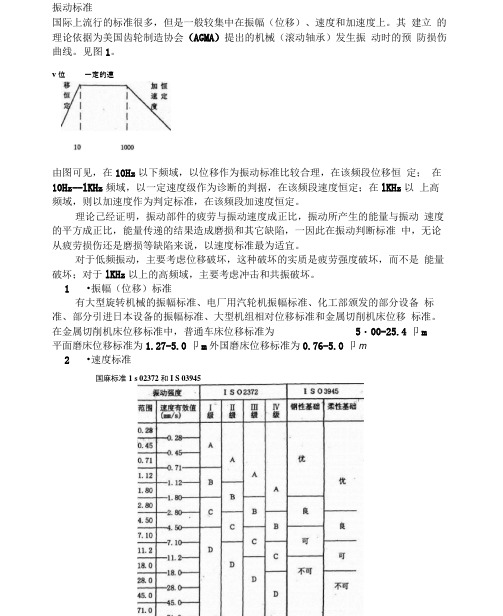
振动标准国际上流行的标准很多,但是一般较集中在振幅(位移)、速度和加速度上。
其建立的理论依据为美国齿轮制造协会(AGMA)提出的机械(滚动轴承)发生振动时的预防损伤曲线。
见图1。
v位一定的速度由图可见,在10Hz以下频域,以位移作为振动标准比较合理,在该频段位移恒定;在10Hz--lKHz频域,以一定速度级作为诊断的判据,在该频段速度恒定;在lKHz以上高频域,则以加速度作为判定标准,在该频段加速度恒定。
理论己经证明,振动部件的疲劳与振动速度成正比,振动所产生的能量与振动速度的平方成正比,能量传递的结果造成磨损和其它缺陷,一因此在振动判断标准中,无论从疲劳损伤还是磨损等缺陷来说,以速度标准最为适宜。
对于低频振动,主要考虑位移破坏,这种破坏的实质是疲劳强度破坏,而不是能量破坏;对于lKHz以上的高频域,主要考虑冲击和共振破坏。
1•振幅(位移)标准有大型旋转机械的振幅标准、电厂用汽轮机振幅标准、化工部颁发的部分设备标准、部分引进日本设备的振幅标准、大型机组相对位移标准和金属切削机床位移标准。
在金属切削机床位移标准中,普通车床位移标准为5・00-25.4卩m平面磨床位移标准为1.27-5.0卩m外国磨床位移标准为0.76-5.0卩m 2•速度标准国麻标准1 s 02372和I S 03945有国际标准ISO2372和3945(见图2)、电机振动速度标准ISO2373轴承的振动速度判据。
3•加速度标准有日本的一般标准齿轮箱诊断标准、滚动轴承的加速度标准、滚动轴承与齿轮箱的“示值”绝对判斯标准。
4•利用冲击系数作判据,判断旋转机械设备轴承的故障类型。
冲击系数是振动峰值与平均值的比值,只有加速度测试值反映峰值,因而冲击系数法只适用于用加速度作为测量参数时。
一般用加速度的高频值和低频值的比较来近似的判断。
判据标准如图3所示:i II 1肿得过簞缺抽Atl諛障英現谕常不是)振动参量的选取2008-12-16 16:15:26来源:作者:【大中小]浏览:门98次评论:0条描述振动和描述一般运动一样,有加速度、速度、一位移三个参量。
30min最高车速标准
30min最高车速标准在国际道路交通安全协会(IRSA)制定的交通安全标准中,30分钟最高车速是一项重要的考量因素。
这一标准旨在确保车辆在道路上的安全行驶,并最大程度地减少交通事故的发生。
以下是与30分钟最高车速标准相关的一些参考内容。
1. 定义和背景:30分钟最高车速标准是指车辆在任何道路上以最高30分钟/公里的速度行驶时所允许的最高速度。
该标准的制定是为了保护行人、车辆和道路设施的安全。
2. 交通安全研究:根据交通安全研究的结果,超过30分钟最高车速的行驶速度将会增加交通事故发生的风险,特别是在城市道路和高峰时间段。
因此,设置适当的最高车速标准是保障道路安全的重要措施。
3. 国家法律和规定:许多国家都制定了关于30分钟最高车速的法律和规定。
这些法律和规定可能会因地区而异,但基本原则是将最高车速限制在不超过30分钟/公里。
4. 道路标志和标线:道路标志和标线是向驾驶员传递交通规则和信息的关键工具。
在与30分钟最高车速标准相关的道路上,应设置适当的标志和标线,以提醒驾驶员注意限制速度。
例如,设置限速标志和限速线等。
5. 驾驶员教育和培训:驾驶员教育和培训是提高道路安全意识和规范驾驶行为的重要手段。
相关的教育和培训课程应当包含对30分钟最高车速的说明和强调,使驾驶员明白在道路上保持适当的速度是确保安全行驶的关键。
6. 执法和罚款措施:对于违反30分钟最高车速标准的驾驶员,应有相应的执法和罚款措施。
这将起到强制作用,迫使驾驶员遵守最高车速限制,并减少交通事故的发生。
7. 科技应用:科技的发展使得交通安全管理更加智能化和高效化。
一些智能交通系统和车辆技术可以监测和控制车辆速度,以保证驾驶员在规定的最高车速范围内行驶。
8. 道路设计和改造:道路设计和改造也是降低交通事故风险的关键因素。
在与30分钟最高车速标准相关的道路上,应采取合适的设计措施,如减速带、限速标线和交通岛等,以降低车辆速度。
总结起来,30分钟最高车速标准在道路交通安全管理中起着至关重要的作用。
ISO362—1:2007在商用车试验中的应用

( 任编辑 责
修 改稿 收到 日期 为 2 1 0 0年 1第 1期
车 辆 加 速行 驶 噪声 测 量 丁 程 法 第 一部 分 : N 类 M、
e g n s wih r s c o e iso o he v ut e i ls n i e t e pe tt m s insf m a y d y v h ce r
EEC,2 05 5 / 0 / 5 EC n 00 78EC. a d 2 5/ /
车 辆 》 与 IO 3 219 S 6 : 8相 比 . O 3 2 1 0 7标 9 I 6— : 0 S 2 准 中 的商用 车试 验 载 荷 、 加速 距 离等 内容产 生 了较
大变 化l 4 l 。 IO 3 2 1 0 7标 准 将 车 辆 的 试 验 分 为 两 大 S 6 — : 0 2 类 : ≤ 35 0k 、 类 车 辆 ,其 试 验 方 法 等 同 于 M2 0 g N1 M1 车 辆 … M2 35 0k 、 2 N 、 类 ; > 0 g N 、 3 M3类 车 辆 试 验 。
d rn o s e t R s a c s ma e t e i l e up e t n n a n u o t r n miso n t e fl wig a p c s u i g n ie t s. e e r h i d o v h ee q i p d wi la n la d a t mai t s s in o h o l n s e t: h c a o
X eD n m n , i B n G oY n , u i o g ig Q u i, u o g MaY e
汽车百米加速 一般标准

汽车百米加速一般标准
百米加速是指汽车在百米距离内从静止加速到最高车速所需要的时间,是衡量汽车动力性能的重要指标之一。
一般来说,汽车的百米加速时间越短,说明车辆的动力性能越好。
根据不同车型和排量,汽车的百米加速时间也有所不同。
一般来说,小型车的百米加速时间在8-12秒之间,紧凑型车在7-9秒之间,中型车在6-8秒之间,豪华车在5-7秒之间。
当然,百米加速时间也受到其他因素的影响,例如车辆重量、轮胎抓地力、发动机功率和扭矩等。
因此,在比较不同车型的百米加速时间时,需要综合考虑这些因素。
减速机制造标准与国家标准
减速机制造标准与国家标准减速机是一种广泛应用于机械传动系统中的重要设备,其质量和性能直接影响到整个传动系统的稳定运行。
因此,制定减速机制造标准和国家标准显得尤为重要。
首先,减速机制造标准是指针对减速机的设计、加工、装配、检验等环节所制定的技术规范。
这些标准的制定,可以规范减速机制造企业的生产行为,保障产品的质量和性能。
在制造标准中,应当包括减速机的设计要求、材料选用、加工工艺、装配要求、检验方法等内容,以确保减速机在使用过程中能够稳定可靠地工作。
其次,国家标准是对减速机产品性能、安全、环保等方面的统一规定。
国家标准的制定,可以帮助减速机制造企业了解国家对减速机产品质量和性能的要求,促进企业提高产品质量,满足市场需求。
在国家标准中,应当包括减速机的技术要求、性能指标、安全要求、环保要求等内容,以确保减速机产品符合国家标准,对用户和环境没有危害。
减速机制造标准和国家标准的制定,需要充分考虑减速机在不同行业的应用特点和需求。
例如,对于矿山、冶金、化工等重工业领域,减速机的耐磨、耐高温、耐腐蚀等性能要求较高;对于食品、医药、轻工等清洁行业,减速机的卫生要求较高。
因此,制定减速机标准需要综合考虑不同行业的需求,确保标准的适用性和实用性。
此外,减速机制造标准和国家标准的制定还需要借鉴国际标准和先进经验。
随着全球化的发展,减速机产品的质量和性能已成为国际贸易的重要议价因素。
因此,制定符合国际标准的减速机制造标准和国家标准,有利于提高我国减速机产品的国际竞争力,拓展国际市场。
综上所述,减速机制造标准和国家标准的制定对于保障减速机产品质量和性能、促进产业升级、拓展国际市场具有重要意义。
我们应当充分认识到这一点,加强标准制定工作,推动减速机行业健康发展。
同时,减速机制造企业应当严格遵守相关标准,不断提升产品质量,满足市场需求,为我国减速机行业的发展做出积极贡献。
国内外铁路客车制动系统标准比对
国内外铁路客车制动系统标准比对■ 王文珺 向世明 武冬生 杨大华(安特百科技术发展有限公司)摘 要:制动性能是反映铁路客车整车质量的重要项目,也是保证铁路客车安全行车的关键因素,本文选取我国与欧洲铁路客车制动系统标准,分别从客车分类、制动系统使用条件、制动系统组成以及制定系统技术要求等四个方面进行了比对分析,提出了我国铁路客车制动系统标准需要完善和修订的内容。
关键词:铁路客车,制动系统,标准DOI编码:10.3969/j.issn.1002-5944.2021.05.030Comparison of Braking System Standards between Chinese and ForeignRailway Passenger CarsWANG Wen-jun XIANG Shi-ming WU Dong-sheng YANG Da-hua(Antpedia Technology Development Co., Ltd.)Abstract: Braking performance is an important item reflecting the quality of the whole train, and it is also a key factor to ensure the safe operation of railway passenger cars. This paper selects the standards of braking system of Chinese and European railway passenger cars, compares and analyzes the classification of passenger cars, service conditions of braking system, composition of braking system and formulation of system technical requirements, and puts forward the contents that need to be improved and revised in China's railway passenger car braking system standards. Keywords: railway passenger cars, braking system, standards标准比对1 引 言铁路客车是各国交通运输系统中的重要运输工具,必须确保其使用安全,而制动性能则是反映铁路客车整车质量的重要项目,也是保证铁路客车安全行车的关键因素[1]。
车辆的加速和减速国际标准

Corresponding author: Rahmi Akçelik Director, Akcelik & Associates Pty Ltd,P O Box 1075 G, Greythorn Victoria, Australia 3104 Tel: +61 3 9857 9351, Fax: + 61 3 9857 5397 rahmi@.au23rd Conference of Australian Institutes of Transport Research (CAITR 2001), Monash University, Melbourne, Australia, 10-12 December 2001Revised: 11 July 2002Acceleration and deceleration modelsRahmi Akçelik and Mark BesleyAkcelik & Associates Pty Ltd1 INTRODUCTIONModelling of acceleration and deceleration distances and times associated with speed change cycles (stop - start and slow down - speed up manoeuvres) under normal driving conditions is essential for the analysis of operating cost, fuel consumption and pollutant emissions, as well as for determining geometric, stopped and queuing components of overall delay (Akcelik and Associates 2002). Similarly, modelling of acceleration and deceleration characteristics of individual vehicles is a key issue in relation to the accuracy of microsimulation models (Akçelik and Besley 2002).A polynomial model of acceleration and deceleration profiles was derived for estimating instantaneous acceleration and deceleration rates, and the model was calibrated using extensive real-life driving data representing general driving conditions, i.e. involving a wide range of speeds change cycles on different road types (Akçelik and Biggs 1987). The model parameters were adjusted for use in intersection analysis on the basis of acceleration and deceleration rates reported in the literature in order to obtain more realistic values representing stop-start conditions at intersections. Further adjustments have been made to model parameters recently for use in aaSIDRA version 2 making use of acceleration time and distance information derived from queue discharge characteristics at signalised intersections (Akcelik and Associates 2002).This paper describes the acceleration and deceleration models, and emphasises the research needs for better model calibration considering different vehicle types (cars, buses, trucks), specific traffic facilities (roundabouts, signalised and sign-controlled intersections, signalised and unsignalised pedestrian crossings, freeways), different traffic demand levels (light, medium, heavy), road types (urban, rural roads, city centre, suburban), and a wide range of initial and final speeds.Figure 1 shows an example of time-distance and speed-time diagrams representing the acceleration and deceleration manoeuvres of a vehicle stopping and starting at traffic signals.2Akçelik and Besleywww.aatraffic .comSpeedFigure 1 - Time-distance and speed-time diagrams showing the acceleration and decelerationmanoeuvres of a vehicle stopping and starting at traffic signalsAcceleration and deceleration models3www.aatraffic.com2 ACCELERATION AND DECELERATION MODELSAcceleration and deceleration distances and times, together with the initial and final speeds during acceleration and deceleration manoeuvres, are the key information for modelling acceleration and deceleration of vehicles. The expressions used in aaSIDRA 2 for estimating acceleration and deceleration distances, times and rates are given below. Default values of model parameters (p 1 to p 7) are given in the aaSIDRA User Guide (Akcelik and Associates 2002).Acceleration and deceleration distances, times and rates for various initial and final speeds for light vehicles are shown in Figures 2 to 4. Acceleration distanceL a m a (v i + v f ) t a / 3.6( 1 )whereL a = acceleration distance (m),v i = initial speed in acceleration (km/h), v f = final speed in acceleration (km/h), t a = acceleration time (seconds), and m a = a model parameter given by:m a = p 1 + p 2 v f - p 3 v i p7 ( 2 ) subject to m amin ≤ m a ≤ m amax m amin = [v i + ρamin (v f - v i )] / (v i + v f ) ( 2a ) m amax = [v i + ρamax (v f - v i )] / (v i + v f ) ( 2b ) ρa = (v a - v i ) / (v f - v i ) ( 3 ) subject to ρamin ≤ ρa ≤ ρamax ρamin = 0.400 ( 3a )ρamax = 0.700( 3b )wherev a = average speed during acceleration (km/h) given by:v a= 3.6 L a / t a( 3c )Deceleration distanceL d = m d (v i + v f ) t d / 3.6( 4 )L d = deceleration distance (m),v i = initial speed in deceleration (km/h), v f = final speed in deceleration (km/h), t d = deceleration time (seconds), and m d = a model parameter given by:m d = p 1 + p 2 v i - p 3 v f p7 ( 5 ) subject to m dmin ≤ m d ≤ m dmax m dmin = [v f + ρdmin (v i - v f )] / (v i + v f ) ( 5a )m dmax = [v f + ρdmax (v i - v f )] / (v i + v f )( 5b )4Akçelik and Besleywww.aatraffic .comρd = (v d - v f ) / (v i - v f ) ( 6 ) subject to ρdmin ≤ ρd ≤ ρdmax ρdmin = 0.400 ( 6a )ρdmax = 0.700( 6b )wherev d = average speed during deceleration (km/h) given by:v d = 3.6 L d / t d ( 3c )Figure 2 - Acceleration and deceleration distances for various initial andfinal speeds (v i ,v f ) for light vehiclesFigure 3 - Acceleration and deceleration times for various initial andfinal speeds (v i ,v f ) for light vehiclesAcceleration and deceleration models5www.aatraffic.comFigure 4 - Average acceleration and deceleration rates for various initial andfinal speeds (v i ,v f ) for light vehiclesAcceleration time and ratet a = (v f - v i ) / a aawhere v f > v i and a ad < 0( 7 )wheret a , v f , v i = as in Equation (1), anda aa = average acceleration rate (m/s 2) calculated as follows:a aa = f aLV [p 1 + p 2 (v f - v i )0.5- p 3 v i ] / 3.6 ( 8 ) for light vehiclesa aa = f aHV [p 1 + p 2 PWR (v f - v i )0.5( 9 )+ PWR 0.5 (p 4 - p 3 v i ) - (p 5 v f 0.5+ p 6 Gr)/ PWR] / 3.6for heavy vehicleswheref aLV = adjustment factor for light vehicle acceleration rates f aHV = adjustment factor for heavy vehicle acceleration rates, Gr = approach grade (per cent)PWR = power to weight ratio calculated from:PWR = 1000 P max / M HV ( 9a )whereP max = maximum rated engine power,M HV = heavy vehicle mass in kg.Default heavy vehicle parameters (representing 5 heavy vehicle classes as used in aaSIDRA 2) are M HV = 11000 kg, P max = 130, PWR = 11.8.6Akçelik and Besleywww.aatraffic .comDeceleration time and ratet d = (v f - v i ) / a ad where v f < v i and a ad < 0 ( 10 )wheret d , v f , v i = as in Equation (4), anda ad = average deceleration rate (m/s 2) calculated as follows:a ad = - f dLV [p 1 + p 2 (v i - v f )0.5- p 3 v f ] / 3.6 ( 11 ) for light vehiclesa ad = -f dHV [p 1 + p 2 PWR (v i - v f )0.5- p 3 v f ( 12 )- p 4M HV 0.5+ p 5 v i + p 6 Gr] / 3.6for heavy vehicleswheref dLV = adjustment factor for light vehicle deceleration rates f dHV = adjustment factor for heavy vehicle deceleration rates, M HV = heavy vehicle mass in kg, and Gr = approach grade (per cent).Acceleration and deceleration profilesThe polynomial model of acceleration and deceleration profiles described by Akçelik and Biggs (1987) can be expressed as follows:a (t) = r a m θ (1 - θm )2( 13 )v (t) = v i + 3.6 r a m t a/d θ2[0.5 - 2 θm/ (m+2) + θ2m/ (2m+2)]subject to m > 0L (t) = v i t / 3.6 + r a m t 2a/d θ3[1/6 - 2 θm/ ((m+2) (m+3))+ θ2m/ ((2m+2) (2m+3))]wherea (t) = acceleration or deceleration rate at time t (m/s 2) (a > 0 for acceleration, a < 0 fordeceleration)v (t) = speed at time t (km/h) L (t) = distance at time t (m)a m = maximum acceleration or deceleration rate (m/s 2) (a ma > 0 for acceleration, a md < 0 fordeceleration) θ = time ratio (θ = t / t a/d , i.e. θ = t / t a or θ = t / t d ) t = time since the start of acceleration (seconds)t a/d = acceleration or deceleration time (t a or t d ) (seconds) v i = initial speed (km/h)m = model calibration parameter, and r=model parameter given by:r = [(1+2 m)2+1/m] / 4 m 2( 13a )The maximum acceleration rate (a m ) and the time when it is reached (θm ) can be determined from:a m = a a / (r q)( 14 )Acceleration and deceleration models 7www.aatraffic.com θm = (1 + 2 m)-1/m( 14a )where a a is the average acceleration rate (m/s2) calculated from Equation (8) or (9) for acceleration or Equation (11) or (12) for deceleration, parameter r is calculated from Equation (13a) and parameter q is calculated from:q = m2 / [(2 m + 2) (m + 2)] ( 14b ) The model is calibrated by determining parameter m using known acceleration distance and time, and initial and final speed values.Recent calibration of the aaSIDRA 2 acceleration models made use of acceleration time and distance information derived from queue discharge characteristics at signalised intersections (Akçelik and Besley 2002).Figures 5 and 6 show the acceleration rate, speed and distance profiles based on the polynomial model for the cases of a light vehicle (i) accelerating from zero initial speed, v i = 0, to a final speed of v f = 60 km/h (acceleration distance, L a = 106.4 m, average acceleration rate, a aa = 1.53 m/s2, maximum acceleration rate, a ma = 2.69 m/s2, acceleration time, t a = 10.9 s, with parameters m a = ρa = 0.587 and v a = 35.2 km/h), and (ii) decelerating from an initial speed of v i = 60 km/h to zero final speed, v f = 0 (deceleration distance, L d = 88.5 m, average deceleration rate, a ad = -1.78 m/s2, maximum deceleration rate, a md = -3.09 m/s2, deceleration time, t d = 9.4 s, with parameters m d = ρd = 0.566 and v d = 34.0 km/h).8Akçelik and Besleywww.aatraffic .comFigure 5 - Polynomial model: Acceleration, speed and distance profiles for a vehicle ACCELERATING from zero initial speed to a final speedof 60 km/hFigure 6 - Polynomial model: Acceleration, speed and distance profiles for a vehicle DECELERATING from an initial speed of 60 km/h to zerofinal speedAcceleration and deceleration models9www.aatraffic.com3 CONCLUSIONFurther research is recommended towards improved calibration of acceleration and deceleration models described in this paper considering:(i) specific traffic facilities (roundabouts, signalised and sign-controlled intersections,signalised and unsignalised pedestrian crossings, freeways), (ii) different vehicle types (cars, buses, trucks),(iii) different traffic demand levels (light, medium, heavy), and (iv) different road types (urban, rural roads, city centre, suburban).Such research would result in acceleration and deceleration models that are more representative of acceleration and deceleration capabilities of the current vehicle fleet, and would reflect driver behaviour in current traffic conditions.This would benefit both analytical and microsimulation models towards achieving better estimates of geometric delay, operating cost, fuel consumption and pollutant emissions.DISCLAIMERThe readers should apply their own judgement and skills when using the information contained in this paper. Although the authors have made every effort to ensure that the information in this report is correct at the time of publication, Akcelik & Associates Pty Ltd excludes all liability for loss arising from the contents of the paper or from its use. Akcelik and Associates does not endorse products or manufacturers. Any trade or manufacturers' names appear in this paper only because they are considered essential for the purposes of this document.REFERENCESAKCELIK & ASSOCIATES (2002). aaSIDRA User Guide . Akcelik and Associates Pty Ltd, Melbourne, Australia.AKÇELIK, R. and BESLEY, M. (2001). Microsimulation and analytical methods for modelling urban traffic. Paper presented at the Conference on Advance Modeling Techniques and Quality of Service in Highway Capacity Analysis , Truckee, California, USA, July 2001. [Available from .au/downloads.htm]AKÇELIK, R. and BIGGS, D.C. (1987). Acceleration profile models for vehicles in road traffic. Transportation Science , 21 (1), pp. 36-54.。
aeb 国际标准

标题:AEB国际标准及其应用引言:AEB(Automatic Emergency Braking)国际标准是一项重要的汽车安全标准,它通过通过自动刹车系统帮助驾驶员避免碰撞事故。
本文将详细介绍AEB国际标准的定义、原理、标准制定过程以及其在实际应用中的意义和效果。
一、AEB国际标准的定义AEB国际标准是指在汽车制造领域中,针对自动刹车系统的技术要求和性能评估所制定的一套标准。
该标准旨在通过利用车辆感知和控制系统,检测前方障碍物并自动刹车,从而避免或减轻碰撞事故的发生。
二、AEB国际标准的原理AEB系统主要由传感器、控制单元和执行机构组成。
传感器负责感知前方的障碍物,如雷达、摄像头等。
控制单元分析传感器获取的数据,并根据预设的算法进行判断和决策。
执行机构则负责对车辆进行制动操作,以实现自动刹车的功能。
三、AEB国际标准的制定过程AEB国际标准的制定是一项复杂而严谨的过程,通常由国际标准化组织和汽车制造商联合进行。
制定过程中包括对AEB技术的研究和测试,并根据实际道路环境和车辆情况进行不断改进和更新。
此外,制定过程还需要考虑法律法规、市场需求和消费者安全等多个因素。
四、AEB国际标准的意义和效果1. 提高行车安全性:AEB系统可以在驾驶员无法及时反应时,自动刹车避免碰撞事故的发生,大大提高行车安全性。
2. 降低交通事故伤害:AEB系统能够在碰撞事故发生前减速或避免碰撞,有效降低交通事故的伤亡程度。
3. 减少车辆损失:AEB系统可以减少碰撞事故对车辆的损坏程度,降低维修和保险成本。
4. 推动汽车行业发展:AEB国际标准的制定促使汽车制造商不断改进和创新技术,推动整个汽车行业向更安全、更智能的方向发展。
五、AEB国际标准在实际应用中的挑战和展望1. 技术难题:AEB系统需要高精度的传感器和快速响应的执行机构,而这些技术仍面临着挑战。
2. 标准统一:不同国家和地区对AEB国际标准的要求存在差异,如何实现标准的统一仍然是一个亟待解决的问题。
- 1、下载文档前请自行甄别文档内容的完整性,平台不提供额外的编辑、内容补充、找答案等附加服务。
- 2、"仅部分预览"的文档,不可在线预览部分如存在完整性等问题,可反馈申请退款(可完整预览的文档不适用该条件!)。
- 3、如文档侵犯您的权益,请联系客服反馈,我们会尽快为您处理(人工客服工作时间:9:00-18:30)。
Corresponding author: Rahmi Akçelik Director, Akcelik & Associates Pty Ltd,P O Box 1075 G, Greythorn Victoria, Australia 3104 Tel: +61 3 9857 9351, Fax: + 61 3 9857 5397 rahmi@.au23rd Conference of Australian Institutes of Transport Research (CAITR 2001), Monash University, Melbourne, Australia, 10-12 December 2001Revised: 11 July 2002Acceleration and deceleration modelsRahmi Akçelik and Mark BesleyAkcelik & Associates Pty Ltd1 INTRODUCTIONModelling of acceleration and deceleration distances and times associated with speed change cycles (stop - start and slow down - speed up manoeuvres) under normal driving conditions is essential for the analysis of operating cost, fuel consumption and pollutant emissions, as well as for determining geometric, stopped and queuing components of overall delay (Akcelik and Associates 2002). Similarly, modelling of acceleration and deceleration characteristics of individual vehicles is a key issue in relation to the accuracy of microsimulation models (Akçelik and Besley 2002).A polynomial model of acceleration and deceleration profiles was derived for estimating instantaneous acceleration and deceleration rates, and the model was calibrated using extensive real-life driving data representing general driving conditions, i.e. involving a wide range of speeds change cycles on different road types (Akçelik and Biggs 1987). The model parameters were adjusted for use in intersection analysis on the basis of acceleration and deceleration rates reported in the literature in order to obtain more realistic values representing stop-start conditions at intersections. Further adjustments have been made to model parameters recently for use in aaSIDRA version 2 making use of acceleration time and distance information derived from queue discharge characteristics at signalised intersections (Akcelik and Associates 2002).This paper describes the acceleration and deceleration models, and emphasises the research needs for better model calibration considering different vehicle types (cars, buses, trucks), specific traffic facilities (roundabouts, signalised and sign-controlled intersections, signalised and unsignalised pedestrian crossings, freeways), different traffic demand levels (light, medium, heavy), road types (urban, rural roads, city centre, suburban), and a wide range of initial and final speeds.Figure 1 shows an example of time-distance and speed-time diagrams representing the acceleration and deceleration manoeuvres of a vehicle stopping and starting at traffic signals.2Akçelik and Besleywww.aatraffic .comSpeedFigure 1 - Time-distance and speed-time diagrams showing the acceleration and decelerationmanoeuvres of a vehicle stopping and starting at traffic signalsAcceleration and deceleration models3www.aatraffic.com2 ACCELERATION AND DECELERATION MODELSAcceleration and deceleration distances and times, together with the initial and final speeds during acceleration and deceleration manoeuvres, are the key information for modelling acceleration and deceleration of vehicles. The expressions used in aaSIDRA 2 for estimating acceleration and deceleration distances, times and rates are given below. Default values of model parameters (p 1 to p 7) are given in the aaSIDRA User Guide (Akcelik and Associates 2002).Acceleration and deceleration distances, times and rates for various initial and final speeds for light vehicles are shown in Figures 2 to 4. Acceleration distanceL a m a (v i + v f ) t a / 3.6( 1 )whereL a = acceleration distance (m),v i = initial speed in acceleration (km/h), v f = final speed in acceleration (km/h), t a = acceleration time (seconds), and m a = a model parameter given by:m a = p 1 + p 2 v f - p 3 v i p7 ( 2 ) subject to m amin ≤ m a ≤ m amax m amin = [v i + ρamin (v f - v i )] / (v i + v f ) ( 2a ) m amax = [v i + ρamax (v f - v i )] / (v i + v f ) ( 2b ) ρa = (v a - v i ) / (v f - v i ) ( 3 ) subject to ρamin ≤ ρa ≤ ρamax ρamin = 0.400 ( 3a )ρamax = 0.700( 3b )wherev a = average speed during acceleration (km/h) given by:v a= 3.6 L a / t a( 3c )Deceleration distanceL d = m d (v i + v f ) t d / 3.6( 4 )L d = deceleration distance (m),v i = initial speed in deceleration (km/h), v f = final speed in deceleration (km/h), t d = deceleration time (seconds), and m d = a model parameter given by:m d = p 1 + p 2 v i - p 3 v f p7 ( 5 ) subject to m dmin ≤ m d ≤ m dmax m dmin = [v f + ρdmin (v i - v f )] / (v i + v f ) ( 5a )m dmax = [v f + ρdmax (v i - v f )] / (v i + v f )( 5b )4Akçelik and Besleywww.aatraffic .comρd = (v d - v f ) / (v i - v f ) ( 6 ) subject to ρdmin ≤ ρd ≤ ρdmax ρdmin = 0.400 ( 6a )ρdmax = 0.700( 6b )wherev d = average speed during deceleration (km/h) given by:v d = 3.6 L d / t d ( 3c )Figure 2 - Acceleration and deceleration distances for various initial andfinal speeds (v i ,v f ) for light vehiclesFigure 3 - Acceleration and deceleration times for various initial andfinal speeds (v i ,v f ) for light vehiclesAcceleration and deceleration models5www.aatraffic.comFigure 4 - Average acceleration and deceleration rates for various initial andfinal speeds (v i ,v f ) for light vehiclesAcceleration time and ratet a = (v f - v i ) / a aawhere v f > v i and a ad < 0( 7 )wheret a , v f , v i = as in Equation (1), anda aa = average acceleration rate (m/s 2) calculated as follows:a aa = f aLV [p 1 + p 2 (v f - v i )0.5- p 3 v i ] / 3.6 ( 8 ) for light vehiclesa aa = f aHV [p 1 + p 2 PWR (v f - v i )0.5( 9 )+ PWR 0.5 (p 4 - p 3 v i ) - (p 5 v f 0.5+ p 6 Gr)/ PWR] / 3.6for heavy vehicleswheref aLV = adjustment factor for light vehicle acceleration rates f aHV = adjustment factor for heavy vehicle acceleration rates, Gr = approach grade (per cent)PWR = power to weight ratio calculated from:PWR = 1000 P max / M HV ( 9a )whereP max = maximum rated engine power,M HV = heavy vehicle mass in kg.Default heavy vehicle parameters (representing 5 heavy vehicle classes as used in aaSIDRA 2) are M HV = 11000 kg, P max = 130, PWR = 11.8.6Akçelik and Besleywww.aatraffic .comDeceleration time and ratet d = (v f - v i ) / a ad where v f < v i and a ad < 0 ( 10 )wheret d , v f , v i = as in Equation (4), anda ad = average deceleration rate (m/s 2) calculated as follows:a ad = - f dLV [p 1 + p 2 (v i - v f )0.5- p 3 v f ] / 3.6 ( 11 ) for light vehiclesa ad = -f dHV [p 1 + p 2 PWR (v i - v f )0.5- p 3 v f ( 12 )- p 4M HV 0.5+ p 5 v i + p 6 Gr] / 3.6for heavy vehicleswheref dLV = adjustment factor for light vehicle deceleration rates f dHV = adjustment factor for heavy vehicle deceleration rates, M HV = heavy vehicle mass in kg, and Gr = approach grade (per cent).Acceleration and deceleration profilesThe polynomial model of acceleration and deceleration profiles described by Akçelik and Biggs (1987) can be expressed as follows:a (t) = r a m θ (1 - θm )2( 13 )v (t) = v i + 3.6 r a m t a/d θ2[0.5 - 2 θm/ (m+2) + θ2m/ (2m+2)]subject to m > 0L (t) = v i t / 3.6 + r a m t 2a/d θ3[1/6 - 2 θm/ ((m+2) (m+3))+ θ2m/ ((2m+2) (2m+3))]wherea (t) = acceleration or deceleration rate at time t (m/s 2) (a > 0 for acceleration, a < 0 fordeceleration)v (t) = speed at time t (km/h) L (t) = distance at time t (m)a m = maximum acceleration or deceleration rate (m/s 2) (a ma > 0 for acceleration, a md < 0 fordeceleration) θ = time ratio (θ = t / t a/d , i.e. θ = t / t a or θ = t / t d ) t = time since the start of acceleration (seconds)t a/d = acceleration or deceleration time (t a or t d ) (seconds) v i = initial speed (km/h)m = model calibration parameter, and r=model parameter given by:r = [(1+2 m)2+1/m] / 4 m 2( 13a )The maximum acceleration rate (a m ) and the time when it is reached (θm ) can be determined from:a m = a a / (r q)( 14 )Acceleration and deceleration models 7www.aatraffic.com θm = (1 + 2 m)-1/m( 14a )where a a is the average acceleration rate (m/s2) calculated from Equation (8) or (9) for acceleration or Equation (11) or (12) for deceleration, parameter r is calculated from Equation (13a) and parameter q is calculated from:q = m2 / [(2 m + 2) (m + 2)] ( 14b ) The model is calibrated by determining parameter m using known acceleration distance and time, and initial and final speed values.Recent calibration of the aaSIDRA 2 acceleration models made use of acceleration time and distance information derived from queue discharge characteristics at signalised intersections (Akçelik and Besley 2002).Figures 5 and 6 show the acceleration rate, speed and distance profiles based on the polynomial model for the cases of a light vehicle (i) accelerating from zero initial speed, v i = 0, to a final speed of v f = 60 km/h (acceleration distance, L a = 106.4 m, average acceleration rate, a aa = 1.53 m/s2, maximum acceleration rate, a ma = 2.69 m/s2, acceleration time, t a = 10.9 s, with parameters m a = ρa = 0.587 and v a = 35.2 km/h), and (ii) decelerating from an initial speed of v i = 60 km/h to zero final speed, v f = 0 (deceleration distance, L d = 88.5 m, average deceleration rate, a ad = -1.78 m/s2, maximum deceleration rate, a md = -3.09 m/s2, deceleration time, t d = 9.4 s, with parameters m d = ρd = 0.566 and v d = 34.0 km/h).8Akçelik and Besleywww.aatraffic .comFigure 5 - Polynomial model: Acceleration, speed and distance profiles for a vehicle ACCELERATING from zero initial speed to a final speedof 60 km/hFigure 6 - Polynomial model: Acceleration, speed and distance profiles for a vehicle DECELERATING from an initial speed of 60 km/h to zerofinal speedAcceleration and deceleration models9www.aatraffic.com3 CONCLUSIONFurther research is recommended towards improved calibration of acceleration and deceleration models described in this paper considering:(i) specific traffic facilities (roundabouts, signalised and sign-controlled intersections,signalised and unsignalised pedestrian crossings, freeways), (ii) different vehicle types (cars, buses, trucks),(iii) different traffic demand levels (light, medium, heavy), and (iv) different road types (urban, rural roads, city centre, suburban).Such research would result in acceleration and deceleration models that are more representative of acceleration and deceleration capabilities of the current vehicle fleet, and would reflect driver behaviour in current traffic conditions.This would benefit both analytical and microsimulation models towards achieving better estimates of geometric delay, operating cost, fuel consumption and pollutant emissions.DISCLAIMERThe readers should apply their own judgement and skills when using the information contained in this paper. Although the authors have made every effort to ensure that the information in this report is correct at the time of publication, Akcelik & Associates Pty Ltd excludes all liability for loss arising from the contents of the paper or from its use. Akcelik and Associates does not endorse products or manufacturers. Any trade or manufacturers' names appear in this paper only because they are considered essential for the purposes of this document.REFERENCESAKCELIK & ASSOCIATES (2002). aaSIDRA User Guide . Akcelik and Associates Pty Ltd, Melbourne, Australia.AKÇELIK, R. and BESLEY, M. (2001). Microsimulation and analytical methods for modelling urban traffic. Paper presented at the Conference on Advance Modeling Techniques and Quality of Service in Highway Capacity Analysis , Truckee, California, USA, July 2001. [Available from .au/downloads.htm]AKÇELIK, R. and BIGGS, D.C. (1987). Acceleration profile models for vehicles in road traffic. Transportation Science , 21 (1), pp. 36-54.。