汇流箱安装(通用)
光伏汇流箱安装
光伏汇流箱安装光伏汇流箱安装指南目录:1.安装前检查2.需要使用的安装工具及零件3.机械安装基本要求3.1 外形尺寸3.2 汇流箱机械安装注意事项3.3 安装方式选择原则4.电气接线及步骤4.1 汇流箱电器安装注意事项4.2 对外接线端子介绍4.3 输入接线4.4 输出连线4.5 通讯接线4.6 端子大小与连接线径5.汇流箱的试运行6.汇流箱的验收1.安装前检查在安装汇流箱之前,必须进行以下检查:检查所有零部件是否完好无损。
检查所有电气元件是否符合要求。
检查所有接线端子是否紧固可靠。
检查所有安装位置是否符合要求。
检查所有安全措施是否已经实施。
2.需要使用的安装工具及零件在安装汇流箱时,需要使用以下工具和零件:扳手螺丝刀铅笔卷尺绝缘胶带接线端子连接线3.机械安装基本要求3.1 外形尺寸在安装汇流箱时,必须保证其外形尺寸符合要求,以确保其能够正常工作。
3.2 汇流箱机械安装注意事项在安装汇流箱时,必须注意以下事项:汇流箱必须安装在平整、干燥、通风的地方。
汇流箱必须与支架紧密连接,以确保其稳定性。
汇流箱必须与其他设备保持一定的距离,以便进行维护和检修。
3.3 安装方式选择原则在选择汇流箱的安装方式时,必须考虑以下因素:安装位置是否符合要求。
汇流箱与其他设备的距离是否合适。
安装方式是否能够保证汇流箱的稳定性。
4.电气接线及步骤4.1 汇流箱电器安装注意事项在安装汇流箱的电器部件时,必须注意以下事项:所有电器元件必须符合要求。
所有接线必须紧固可靠。
所有接线必须正确连接。
4.2 对外接线端子介绍在安装汇流箱时,必须了解其对外接线端子的功能和使用方法。
4.3 输入接线在安装汇流箱时,必须正确连接输入接线。
4.4 输出连线在安装汇流箱时,必须正确连接输出连线。
4.5 通讯接线在安装汇流箱时,必须正确连接通讯接线。
4.6 端子大小与连接线径在安装汇流箱时,必须选择正确的端子大小和连接线径,以确保电气连接的可靠性和安全性。
汇流箱安装验收记录
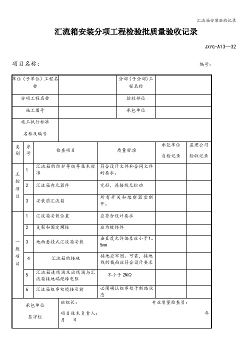
汇流箱组串电缆接引前
必须确认组串处于断路状态
承包单位
签字栏
班组长:专业质量检查员:
项目技术负责人:年月日
EPC总承包单位签ຫໍສະໝຸດ 栏项目技术负责人:年月日监理公司
签字栏
专业监理工程师:
年月日
本表一式4份,建设管理单位存1份、项目监理部存1份、承包单位存2份.
汇流箱内元器件
完好,连接线无松动
3
安装前汇流箱
所有开关和熔断器宜断开。
一般项目
1
汇流箱安装位置
应符合设计要求
2
支架和固定螺栓
应为镀锌件
3
地面悬挂式汇流箱安装
垂直度允许偏差应小于1。5mm
4
汇流箱的接地
接地应牢固、可靠,接地线的截面应符合设计要求
5
汇流箱进线端及出线端与汇流箱接地端绝缘电阻
不小于2MΩ
汇流箱安装分项工程检验批质量验收记录
JXYG-A13—32
项目名称:编号:
单位(子单位)工程名称
分部(子分部)工程名称
分项工程名称
验收部位
施工图号
承包单位
施工执行标准
名称及编号
类别
序号
检查项目
质量标准
承包单位
自检记录
监理公司
验收记录
主控项目
1
汇流箱的防护等级等技术标准
符合设计文件和合同文件的要求。
2
汇流箱使用手册

京仪绿能JINGY1 RENEWABLE ENERGYJYHL-8IN光伏阵列汇流箱使用手册北京京仪绿能电力系统工程有限公司北京京仪绿能电力系统工程有限公司• JYHL-8IN-201004 •版本:1.0目录1. 符号解释............................................................... 1.2. 安全说明............................................................... 2.3. 简介................................................................... 3.3.1. 供货范围.......................................................... 3.3.2. 型号说明..........................................................4.3.3. 铭牌..............................................................4.4. 系统结构............................................................... 6.4.1. 内部结构.......................................................... 6.4.2. 保险丝等级........................................................ 7.4.3. 直流断路器等级.................................................... 7.5. 安装与使用............................................................. 8.5.1. 安装前检查........................................................ 8.5.2. 需要使用的安装工具及零件 (8)5.3. 机械安装.......................................................... 9.5.3.1. 外型尺寸..................................................... 9.5.3.2. 基本安装要求................................................. 9.5.3.3. 机箱的开启与关闭 (10)5.4. 电气接线及步骤 (11)5.4.1. 对外接线端子介绍 (11)5.4.2. 端子大小与连接线径 (12)5.4.3. 对外接线操作步骤 (13)5.5. 更换保险丝 (15)6. 技术数据 (16)7. 附录 (17)7.1. 质量保证 (17)7.2. 联系我们 (17)1. 符号解释为了更好的使用本手册,请仔细阅读以下符号说明此符号标识对于如果不当操作则可能对用户的安全产生危险和(或)可能造成重大硬件损坏的注意事项或者说明。
电气连接和汇流箱安装施工方案
电气连接和汇流箱安装施工方案安徽省阜阳市颖东区新乌江镇的永明20MW农光互补分布式光伏发电项目需要进行汇流箱电气安装。
以下是该项目的汇流箱安装作业施工方案。
第一章:编制依据本方案的编制依据包括项目相关技术文件、设计文件和标准规范等。
第二章:工程概述该项目是一项分布式光伏发电项目,位于安徽省阜阳市颖东区新乌江镇永明地区。
总装机容量为20MW。
第三章:施工管理目标3.1质量目标保证施工质量符合相关标准和规范要求。
3.2安全目标确保施工过程中人员和设备的安全。
3.3进度目标按照工期要求保质保量完成施工任务。
第四章:施工准备4.1技术准备施工前需对相关技术进行了解和熟悉,确保施工质量。
4.2施工机械设备准备准备必要的施工机械设备,包括吊车、脚手架等。
第五章:施工工序及主要施工工艺5.1施工工序施工工序包括:现场勘测、基础施工、架设支架、电缆敷设、汇流箱安装等。
5.2汇流箱安装施工方法及工艺5.2.1施工准备准备必要的工具和设备,包括电缆、电缆槽、连接器等。
同时,对施工现场进行检查,确保安全。
以下省略,因为剩下的内容格式错误且无法改写)Chapter 1: Basis for nXXX plan for the 20MW distributed photovoltaic power n project in Yongming。
New Wujiang Town。
Yingdong District。
Fuyang City。
Anhui Province:1.XXX n n)2.The company's current comprehensive management system for quality。
environment。
XXX and safety3.Technical ns。
ns。
and standards related to this project issued by the state and the power XXX laws。
光伏电站逆变器、汇流箱安装检查表

合格不合格
逆变器端交流线缆连接
逆变器交流输出线连接极性正确(交流线缆与接头接线孔对应关系正确,L1,L2,L3对应孔1,2,3)
合格不合格
交流接头加工时线缆皮无破损,无漏铜丝现象
合格不合格
线缆与接头连接螺丝牢固,无松动
逆变器、汇流箱安装检查表
检查大项
检查子项
检查结果
备注
逆变器安装
机箱编号清晰
合格不合格
逆变器安装牢固,背板和底部连接螺丝紧固到位
合格不合格
逆变器安装不得前倾
合格不合格
逆变器端线缆布放总体要求
各类线缆自然下垂固定,应力小
合格不合格
线缆标识清晰
合格不合格
未接线的接口盖好防尘堵头
合格不合格
逆变器保护地线连接
合格不合格
通信线缆按照设计图纸连接
合格不合格
汇流箱安装检查
机箱编号清晰
合格不合格
线缆与空开之间的对应关系标识清晰
合格不合格
线缆连接可靠,OT端子压接牢固,OT端子柄和铜芯无外露,用绝缘胶带缠紧或套热缩套管
合格不合格
线缆OT端子与断路器连接螺丝紧固到位
合格不地可靠连接
合格不合格
并网检查
查看逆变器输出参数中电压测量值与实际电压等级一致,电网频率与当地电网频率一致
合格不合格
对于额定电压480V的逆变器(28KTL、40KTL)满载时逆变器端口交流电压不能超过520Vac
合格不合格
合格不合格
交流接头与逆变器连接可靠,接头外护套紧固到位
合格不合格
交流接头密封圈用扳手拧紧,无松动
汇流箱及逆变器的安装调试技术方案
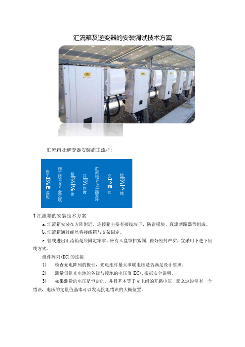
汇流箱及逆变器的安装调试技术方案汇流箱及逆变器安装施工流程:1汇流箱的安装技术方案a.汇流箱安装在方阵附近,连接箱主要有接线端子、防雷模块、直流断路器等组成。
b.汇流箱通过螺丝将接线箱与支架固定。
c.管线进出汇流箱是应固定牢靠,应有入盒锁扣紧固,做好密封严实,宜采用下进下出线方式。
组件阵列(DC)的连接1) 检查光电阵列的极性,光电组件最大串联电压是否满足设计要求。
2) 测量每组光电池的各级与接地的电压值(DC),根据安全说明。
3)如果测量的电压是恒定的,并且基本等于光电组的开路电压,那么这说明有一个错误,电压的定量值基本可以发现接地错误的大概位置。
检l ⅞l^线交I ^E验汇流箱⅛a⅛{器安装开l ⅞作收基l ⅛l⅛收施工技¼⅛w 全交底施工I ⅞E编制4)连接没有问题的光电组到逆变器。
并确认连接到正确的接线端子和极性。
d.并网前汇流箱、并置箱、总箱检查1)检查汇流箱内所有接线,需牢固可靠。
2)用万用表测量极性是否正确,开路电压是否符合要求。
3)紧固箱内所有接线螺栓。
4)确保所有断路器处于OFF状态。
e.光伏发电项目汇流箱安装质量标准及检查验收方法工序检查验收项目性质单位质量标准检查验收方法和器具设备检查防护等级符合设计、合同要求观察外形尺寸符合图纸用钢尺检测元器件完好、无松动内部检查开关和熔断器主要断开灵活、可靠操作试验设备位置符合图纸设计核对图纸检查支架和固定螺栓镀锌件外观检查垂直度mm允许偏差应小于1.5mm港"接地应牢固、可靠对照标准检查接地线的截面符合设计要求卡尺实测绝缘电阻测试汇流箱进线端与接地端绝缘电阻主要MC绝缘电阻不小于2MQ用兆欧表测试汇流箱进线端与接地端绝缘电阻主要MΩ绝缘电阻不小于2MQ用兆欧表测试2逆变器的安装技术方案a.逆变器在运输过程中要固定牢靠,防止磕碰,避免元件、仪表及油漆的损坏。
b.逆变器到场后,应开箱检查规格型号是否与设计相符,柜内零件和备品是否齐全,有无出厂合格证、说明书、出厂报告等技术文件。
060 直流汇流布线及汇流箱安装作业指导书
58.直流汇流布线及汇流箱安装(一、工程概述****光伏并网发电项目位于****,本期工程共设计ZRC-YJV-0.6/1KV-2x50、ZRC-YJV-0.6/1KV-2x70、ZRC-YJV-0.6/1KV-1x4 三种型号的直流汇流电缆610公里,设计GHL-112/15-SRO型光伏防雷汇流箱880只。
二、编制依据1、****电力设计院施工图纸2、《光伏发电系统施工组织总设计》3、《电气装置安装工程电缆线路施工及验收规范》GB50168-20064、《电气装置安装工程接地装置施工及验收规范》GB50169-20065、《电气装置安装工程质量检验及评定规程》DL/T 5161.1--5161.17-20026、《电力建设安全工作规程》(火力发电厂部分)DL5009.1-20027、《绿色施工导则》建质[2007]233号8、《光伏发电站施工质量检查及验收规程》试行版9、****厂家图纸三、施工准备四、主要施工方案1、汇流箱支架采用热镀锌槽钢、热镀锌角钢制作,焊接后使用热镀锌螺栓固定到光伏支架上。
2、直流汇流电缆采用挖沟直埋敷设方式,电缆上、下方应按照设计要求使用软土、细砂进行防护,电缆过路处应穿管敷设。
3、光伏支架上安装的直流汇流电缆应使用绑线牢固绑扎。
4、直流汇流电缆穿入汇流箱后应按图纸设计的回路号接线。
5、直流汇流电缆保护管安装高度应一致,穿线后用防火材料严密封堵。
五、施工工艺流程六、施工注意事项1、所有施工人员,必须经体检合格并通过三级安全教育,持证上岗,严格按技术交底要求进行施工。
2、对照图纸,领取所需设备、材料,并检验型号及规格符合设计要求。
3、使用电焊机必须配备面罩和焊工手套,施工中有水及焊接手套潮湿后不得进行焊接作业,严禁利用钢筋、角铁、槽钢等作为电焊机接地线。
4、焊机要接地良好,电焊机使用前必须检查其绝缘,电源线及电焊导线严禁破损漏电,严禁使用破旧、淘汰的焊机。
5、使用切割机、无齿锯时必须佩戴防护眼镜,且锯前方不准朝向路口或行人,施工时应安排熟练工进行操作,并严格遵守操作规程。
汇流箱使用手册

JYHL-8IN 光伏阵列汇流箱使用手册北京京仪绿能电力系统工程有限公司北京京仪绿能电力系统工程有限公司●JYHL-8IN-201004 ●版本:1.0目录1. 符号解释 (1)2. 安全说明 (2)3. 简介 (3)3.1. 供货范围 (3)3.2. 型号说明 (4)3.3. 铭牌 (4)4. 系统结构 (6)4.1. 内部结构 (6)4.2. 保险丝等级 (7)4.3. 直流断路器等级 (7)5. 安装与使用 (8)5.1. 安装前检查 (8)5.2. 需要使用的安装工具及零件 (8)5.3. 机械安装 (9)5.3.1. 外型尺寸 (9)5.3.2. 基本安装要求 (9)5.3.3. 机箱的开启与关闭 (10)5.4. 电气接线及步骤 (11)5.4.1. 对外接线端子介绍 (11)5.4.2. 端子大小与连接线径 (12)5.4.3. 对外接线操作步骤 (13)5.5. 更换保险丝 (15)6. 技术数据 (16)7. 附录 (17)7.1. 质量保证 (17)7.2. 联系我们 (17)1.符号解释为了更好的使用本手册,请仔细阅读以下符号说明。
警告!此符号标识对于如果不当操作则可能对用户的安全产生危险和(或)可能造成重大硬件损坏的注意事项或者说明。
说明!此符号标识使得系统良好工作所需的重要注意事项。
2.安全说明安装前请仔细阅读本手册,若未按本手册中的说明辦行安装而出现设备损坏,本公司有权不予质量保证。
3.简介对于大型光伏并网发电系统,为了减少光伏组件与逆变器之间连接线,方便维护,提高可靠性,一般需要在光伏组件与逆变器之间增加直流汇流装置。
本公司的光伏阵列汇流箱系列产品就是为了满足这一要求而特别设计的,可与本公司的光伏逆变器产品相配套组成完整的光伏发电系统解决方案。
使用光伏阵列汇流箱,用户可以根据逆变器输入的直流电压范围,把一定数量的规格相同的光伏组件串联组成 1 个光伏组件串列,再将若干个串列接入光伏阵列防雷汇流箱,通过防雷器与断路器后输出,方便了后级逆变器的接入。
汇流箱组串逆变器安装
重大综合一般林州市横水镇60MWp光伏发电项目汇流箱组串逆变器安装方案编制:审核:批准:目录一、适用范围..................................错误!未定义书签。
二、作业前应做的准备及必须具备的条件..........错误!未定义书签。
三、主要工具配置图............................错误!未定义书签。
四、汇流箱施工安装规范........................错误!未定义书签。
五、组串逆变器施工安装规范 (2)六、注意事项 (2)七、安装质量控制及检验 (3)八、职业健康安全与环境管理 (3)一、适用范围此施工工法适用于光伏区的汇流箱及组窜逆变器的安装施工。
二、作业前应做的准备及必须具备的条件2.1参加作业人员的资格及要求(包括人员等级及数量、人员考核、人员责任)。
2.2作业所需工具及仪器、仪表和准确度的要求。
2.3 汇流箱及组串逆变的规格、类型各项设计标准符合规范要求有出厂合格证。
2.4 检查汇流箱及组串逆变器,如有表面损伤、变形及松动等问题,应及时进行修整、校正等处理,合格后才能进行安装。
2.5 作业环境应达到的条件。
2.6 安装前检查,在技术协议书中会对汇流箱的防护等级,元器件的品牌和型号做出相应的要求,安装前应进行检查;经过长途运输和现场保管应对箱内元器件及连线进行检查,是否存在破损和松动现象。
三、主要工具配置安装工具选用:绝缘电阻测试仪、一字螺丝刀、十字螺丝刀、力矩扳手、扳手、斜口钳、卷尺、万用表、角尺、热风机、绝缘摇表等。
四、汇流箱施工安装规范依据《光伏发电工程验收规范》GB50796-20124.1施工安装步骤:汇流箱检验→汇流箱固定支架制作→汇流箱固定及安装→汇流箱接地→汇流箱安装验收4.2汇流箱安装注意事项1、安装情况:检查汇流箱高度、位置、水平度应符合设计及合同要求。
2、标识:检查汇流箱标识应齐全。
3、连接:检查箱体和支架连接牢固。
汇流箱安装(通用)
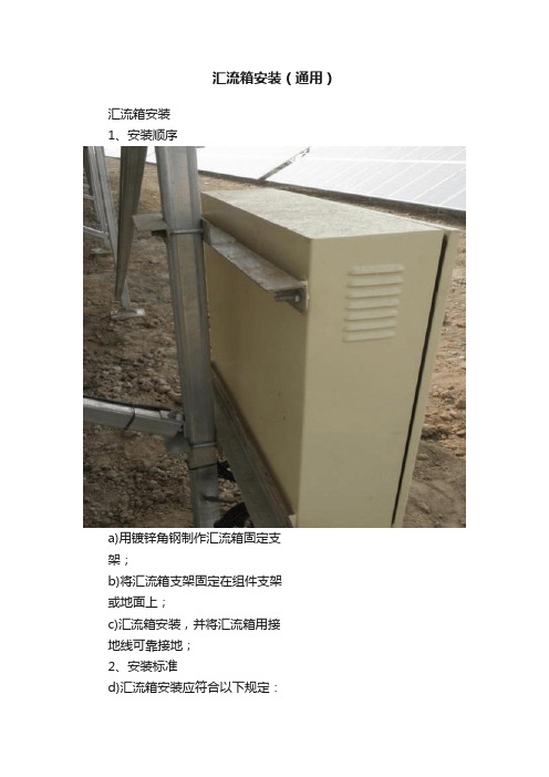
汇流箱安装(通用)
汇流箱安装
1、安装顺序
a)用镀锌角钢制作汇流箱固定支
架;
b)将汇流箱支架固定在组件支架
或地面上;
c)汇流箱安装,并将汇流箱用接
地线可靠接地;
2、安装标准
d)汇流箱安装应符合以下规定:
e)位置正确、部件齐全、箱体开孔合适、切口整齐、箱体紧贴墙面;无绞线现象,油漆完
整、盘内外清洁、箱盖开关灵活、回路编号齐全、接线整齐、PE 保护地线安装明显、牢固;导线截面、相色符合规范规定。
f)汇流箱外壳应有明显可靠的PE 保护地线(PE 为黄绿相间的双色线);但PE保护地线
不允许利用箱体或盒体串连。
g)汇流箱配线排列整齐,并绑扎成束;在活动部位应固定;盘面引出及引进的导线应留有
适当余度,以便于检修。
h)汇流箱内刀闸及保险等,均应处于断路状态。
i)电气设备、器具和非带电金属部件的保护接地支线敷设应符合以下规定:
连接紧密、牢固;保护地线截面选用正确,需防腐的部分涂漆均匀无遗漏;线路走向合理、色标准确、涂刷后不污染设备和墙面。
检验方法:观察检查。
允许偏差:体高50mm 以下允许偏差1.5mm;体高50mm 以上允许偏差3mm。
汇流箱、箱变、逆变安装资料概论

1区汇流箱安装分项工程质量检验评定表工程编号:03-03-011区汇流箱汇线分项工程质量检验评定表工程编号:09-01-00-041区汇流箱汇线分项工程质量检验评定表(续表)工程编号:09-01-00-041#箱式变压器本体安装分项工程质量检验评定表1#区逆变器安装分项工程质量检验评定表1#区逆变器安装分项工程质量检验评定表(续表)2#区支架安装质量验收记录表编号:09-02-00-012#区组件安装质量验收记录表编号:09-02-00-022区汇流箱安装分项工程质量检验评定表工程编号:09-02-00-032区汇流箱汇线分项工程质量检验评定表工程编号:09-02-00-042区汇流箱汇线分项工程质量检验评定表(续表)工程编号:09-02-00-042#箱式变压器本体安装分项工程质量检验评定表工程编号:09-02-00-052#区逆变器安装分项工程质量检验评定表2#区逆变器安装分项工程质量检验评定表(续表)3#区支架安装质量验收记录表3#区组件安装质量验收记录表编号:09-03-00-023区汇流箱安装分项工程质量检验评定表工程编号:09-03-00-033区汇流箱汇线分项工程质量检验评定表工程编号:09-03-00-043区汇流箱汇线分项工程质量检验评定表(续表)工程编号:09-03-00-043#箱式变压器本体安装分项工程质量检验评定表工程编号:09-03-00-053#区逆变器安装分项工程质量检验评定表3#区逆变器安装分项工程质量检验评定表(续表)4#区支架安装质量验收记录表编号:09-04-00-014#区组件安装质量验收记录表4区汇流箱安装分项工程质量检验评定表工程编号:09-04-00-034区汇流箱汇线分项工程质量检验评定表工程编号:09-04-00-044区汇流箱汇线分项工程质量检验评定表(续表)工程编号:09-04-00-044#箱式变压器本体安装分项工程质量检验评定表工程编号:09-04-00-054#区逆变器安装分项工程质量检验评定表4#区逆变器安装分项工程质量检验评定表(续表)5#区支架安装质量验收记录表编号:09-05-00-015#区组件安装质量验收记录表编号:09-05-00-025区汇流箱安装分项工程质量检验评定表5区汇流箱汇线分项工程质量检验评定表工程编号:09-05-00-045区汇流箱汇线分项工程质量检验评定表(续表)工程编号:09-05-00-045#箱式变压器本体安装分项工程质量检验评定表工程编号:09-05-00-055#区逆变器安装分项工程质量检验评定表5#区逆变器安装分项工程质量检验评定表(续表)6#区支架安装质量验收记录表编号:09-06-00-016#区组件安装质量验收记录表编号:09-06-00-026区汇流箱安装分项工程质量检验评定表工程编号:09-06-00-036区汇流箱汇线分项工程质量检验评定表工程编号:09-06-00-046区汇流箱汇线分项工程质量检验评定表(续表)工程编号:09-06-00-046#箱式变压器本体安装分项工程质量检验评定表工程编号:09-06-00-056#区逆变器安装分项工程质量检验评定表6#区逆变器安装分项工程质量检验评定表(续表)7#区支架安装质量验收记录表编号:09-07-00-017#区组件安装质量验收记录表7区汇流箱安装分项工程质量检验评定表7区汇流箱汇线分项工程质量检验评定表工程编号:09-07-00-04。
电气安装规范
山东天裕新能源工程有限公司光伏场区电气设备安装规范一、汇流箱安装(1)汇流箱安装前应做如下准备:1)汇流箱的防护等级等技术标准应符合设计文件和合同文件的要求。
2)汇流箱内元器件完好,连接线无松动。
3)安装前汇流箱的所有开关和熔断器宜断开。
(2)汇流箱安装应符合以下要求:1)安装位置应符合设计要求。
支架和固定螺栓应为镀锌件。
2)屋面卧式汇流箱安装的角度应符合设计要求。
3)汇流箱的接地应牢固、可靠。
接地线的截面应符合设计要求。
4) 汇流箱进线端及出线端与汇流箱接地端绝缘电阻不小于2MΩ(DC1000V)。
5)汇流箱组串电缆接引前必须确认组串处于断路状态。
(3)汇流箱接线1)汇线完毕应按施工图检查核对汇线是否正确。
在会流箱接线端子处检测电压、电流、正负极是否正确。
2)组件接线盒出口处的连接线应向下弯曲防雨水流入接线盒。
3)方阵汇线及检测完毕应盖上并锁紧所有汇流箱门。
4)方阵的输出端应有明显的极性标志和子方阵的编号标志。
5)将电池板串联的连线接入汇线箱内再用铠装电缆接入逆变柜,电缆的金属铠装应做接地处理。
4)汇流箱施工安装要求及流程;A.箱体定位螺栓固定箱面组装符合图纸B.汇流箱应安装在安全、干燥、易操作的位置。
C.汇流箱作好明显可靠的接地;导线引出面板时,面板线孔应光滑无毛刺;金属面板应装设绝缘保护套。
D.汇流箱外壳应有明显可靠的PE保护地线(PE为黄绿相间的双色线);但PE 保护地线不允许利用箱体或盒体串连。
E.并绑扎成束:在活动部位应固定;盘面引出及引进的导线应留有适当余度,以便于检修。
F.PE保护地线若不是供电电缆或电缆外护层的组成部分时,按机械强度要求,截面不应小于下列数值:有机械保护时为2.5mm2;无机械保护时为4mm2;G.绝缘摇测:汇流箱全部安装完毕后,用500V兆欧表对线路进行绝缘摇测。
两人进行摇测,同时做好记录,作为技术资料存档。
5)质量标准A.接地保护措施和其他安全要求必须符合施工验收规范规定。
简述汇流箱投入运行及退出运行的操作步骤
简述汇流箱投入运行及退出运行的操作步骤汇流箱(也称为集电箱)是太阳能光伏系统中的一个关键组件,用于收集和分配太阳能电池板产生的电能。
以下是汇流箱投入运行和退出运行的一般操作步骤:汇流箱投入运行的操作步骤:1. 检查安装:确保汇流箱已正确安装在光伏系统中,并且所有连接都牢固。
检查电缆和连接器的状态,确保没有松动或损坏的部分。
2. 检查电缆:检查电缆的绝缘状况,确保没有暴露的金属部分。
如果发现问题,及时修复或更换电缆。
3. 检查防护:确保汇流箱的外壳和接线端子处于良好状态,以防止环境因素对电气部件的影响。
4. 连接电池板:将太阳能电池板的输出电缆连接到汇流箱的输入端子。
确保连接正确,正负极对应。
5. 检查参数设置:检查汇流箱的参数设置,包括电流和电压等参数。
根据实际情况进行必要的调整,确保适应光伏系统的要求。
6. 开启断路器:如果系统中有断路器,确保将其打开,使电流流通。
7. 监测运行状态:启动光伏系统并监测汇流箱的运行状态。
使用监控设备或系统控制器来确保电流和电压在正常范围内。
汇流箱退出运行的操作步骤:1. 关闭断路器:首先,关闭光伏系统中的断路器,停止电流流通。
2. 断开电池板连接:断开太阳能电池板的输出电缆与汇流箱的输入端子的连接。
3. 检查运行状态:在断开连接之前,再次检查汇流箱的运行状态,确保系统处于安全状态。
4. 断开电缆:断开与汇流箱相关的电缆连接,确保安全地解开连接。
5. 关闭系统:如果需要,关闭整个光伏系统。
这可能包括关闭逆变器或其他关键组件。
6. 维护和检修:定期对汇流箱进行维护和检修,确保其长期可靠运行。
这可能包括清理外壳、检查接线端子、更换损坏的部件等。
7. 记录数据:在退出运行之前,记录系统的性能数据,以便后续分析和维护。
这可以帮助识别潜在问题并提高系统的效率。
请注意,具体的操作步骤可能会因制造商、型号和系统配置而有所不同,因此在执行任何操作之前,应参考相关的用户手册和安装指南。
光伏发电项目汇流箱安装质量标准及检查验收方法

光伏发电项目汇流箱安装质量标准及检查验收方法
汇流箱安装
工序检查验收项目性
质
单
位
质量标准检查验收方法和器具
设备检查防护等级符合设计、合同要求观察
外形尺寸符合图纸用钢尺检测元器件完好、无松动内部检查开关和熔断器
主
要
断开灵活、可靠操作试验
设备位置符合图纸设计核对图纸检查支架和固定螺栓镀锌件外观检查
垂直度mm 允许偏差应小于1.5mm 测量
接地应牢固、可靠对照标准检查接地线的截面符合设计要求卡尺实测
绝缘电阻测试汇流箱进线端与接地端
绝缘电阻
主
要
MΩ绝缘电阻不小于2MΩ用兆欧表测试汇流箱进线端与接地端
绝缘电阻
主
要
MΩ绝缘电阻不小于2MΩ用兆欧表测试。
(完整版)汇流箱技术协议(通用)

*****光伏并网项目汇流箱技术协议**年**月目录1通用部分 (3)1.1电站工程概况 (3)1.2电站环境条件 (3)1.3供货范围 (3)1.4备品备件 (4)1.5专用工器具 (4)1.6标准和规程 (5)1.7材料、工厂涂漆和保护涂层 (6)1.8铭牌与标志 (6)1.9工厂组装、试验见证 (7)1.10责任认定 (7)2专用部分 (8)2.1汇流箱总体要求 (8)2.2汇流箱技术性能要求 (8)2.3汇流箱内主要元件要求 (9)2.4关键元器件要求 (13)2.5电气参数范围 (15)1通用部分1.1 电站工程概况1.1.1 项目名称:××××1.1.2 工程地址:××××1.1.3 运输方式:公路或铁路1.2 电站环境条件1.2.1 环境条件1.3 供货范围1.3.1供货范围汇流箱台数、型号及用途见表1-1表1.1 供货范围任何元件、装置或附件,如果上述条款中并未专门提到,但它对于一个完整的性能优良的汇流箱设备又是必不可少的,那么这些元件、装置或附件也应属于供货范围,其费用含在总价中。
设备详细元器件表:1.4 备品备件备品备件与原附件应具有相同的材料和质量,可以互换,并经过与原附件同样的工厂检查和试验。
备品备件应包括必需的安装材料。
备品备件应按要求进行处理和保护,以保证长期贮存不坏。
备品备件包装箱应有清楚的标记。
卖方应提供备品备件的技术参数和使用说明书等资料。
表1.2 备品备件1.5 专用工器具专用工器具是为便于汇流箱及其附属设备安装、搬运、运行、维修所必需的。
卖方应提供专用工器具的技术参数和使用说明书等资料。
表1.3 专用工器具1.6 标准和规程1.6.1 本范围内的设备应首先采用中华人民共和国国家标准及部颁标准和行业标准,在国内标准不完善的情况下,可采用相应的国际标准(如IEC、IEEE等)中最适宜的条款部分或双方认定的其他国家标准。
汇流箱、箱变、逆变安装资料

1区汇流箱安装分项工程质量检验评定表工程编号:03-03-011区汇流箱汇线分项工程质量检验评定表工程编号:09-01-00-041区汇流箱汇线分项工程质量检验评定表(续表)工程编号:09-01-00-041#箱式变压器本体安装分项工程质量检验评定表1#区逆变器安装分项工程质量检验评定表1#区逆变器安装分项工程质量检验评定表(续表)编号:09-02-00-01编号:09-02-00-022区汇流箱安装分项工程质量检验评定表工程编号:09-02-00-032区汇流箱汇线分项工程质量检验评定表工程编号:09-02-00-042区汇流箱汇线分项工程质量检验评定表(续表)工程编号:09-02-00-042#箱式变压器本体安装分项工程质量检验评定表2#区逆变器安装分项工程质量检验评定表2#区逆变器安装分项工程质量检验评定表(续表)编号:09-03-00-01编号:09-03-00-023区汇流箱安装分项工程质量检验评定表工程编号:09-03-00-033区汇流箱汇线分项工程质量检验评定表工程编号:09-03-00-043区汇流箱汇线分项工程质量检验评定表(续表)工程编号:09-03-00-043#箱式变压器本体安装分项工程质量检验评定表3#区逆变器安装分项工程质量检验评定表3#区逆变器安装分项工程质量检验评定表(续表)编号:09-04-00-01编号:09-04-00-024区汇流箱安装分项工程质量检验评定表工程编号:09-04-00-034区汇流箱汇线分项工程质量检验评定表工程编号:09-04-00-044区汇流箱汇线分项工程质量检验评定表(续表)工程编号:09-04-00-044#箱式变压器本体安装分项工程质量检验评定表4#区逆变器安装分项工程质量检验评定表4#区逆变器安装分项工程质量检验评定表(续表)编号:09-05-00-01编号:09-05-00-025区汇流箱安装分项工程质量检验评定表工程编号:09-05-00-035区汇流箱汇线分项工程质量检验评定表工程编号:09-05-00-045区汇流箱汇线分项工程质量检验评定表(续表)工程编号:09-05-00-045#箱式变压器本体安装分项工程质量检验评定表5#区逆变器安装分项工程质量检验评定表5#区逆变器安装分项工程质量检验评定表(续表)编号:09-06-00-01编号:09-06-00-026区汇流箱安装分项工程质量检验评定表工程编号:09-06-00-036区汇流箱汇线分项工程质量检验评定表工程编号:09-06-00-046区汇流箱汇线分项工程质量检验评定表(续表)工程编号:09-06-00-046#箱式变压器本体安装分项工程质量检验评定表6#区逆变器安装分项工程质量检验评定表6#区逆变器安装分项工程质量检验评定表(续表)编号:09-07-00-01编号:09-07-00-027区汇流箱安装分项工程质量检验评定表工程编号:09-07-00-037区汇流箱汇线分项工程质量检验评定表工程编号:09-07-00-04。
比亚迪电池盒高压汇流箱安装手册说明书

Battery-Box Premium HVS/HVM Combiner Box Installation Manual Model: CBH-40AV1.2BYD Smart Device Hungary Kft.Battery Box Premium HVS/HVM Combiner Box BYD Smart Device Hungary Kft.Legal ProvisionsAll the information in this document is the property of BYD Smart Device Hungary Kft. No partof this document could be reproduced in any way for business use. Internal use is allowed.BYD Smart Device Hungary Kft. makes no representations or warranties express or implied, with respect to this document, including (with no limitation) any implied warranties of utility, merchantability, or fitness for any particular purpose. All such representations or warranties are expressly disclaimed. Neither BYD Smart Device Hungary Kft. nor its distributors or dealers shallbe liable for any indirect, incidental, or consequential damages under any circumstances.The exclusion of implied warranties may not apply in all cases under some statutes, and thus the above exclusion may not apply.This document does not replace and is not intended to replace any local, state, provincial, federal, or national laws, regulations, or codes applicable to the installation, electrical safety, and use of the battery system. BYD Smart Device Hungary Kft. assumes no responsibility for the compliance or noncompliance with such laws or codes in connection with the installation of the battery system. Specifications are subject to change without notice. Every effort has been made to make this document complete, accurate, and up-to-date. However, BYD Smart Device Hungary Kft. may need to make some improvements under certain circumstances without advance notice. BYD Smart Device Hungary Kft. shall not be responsible for any loss caused by this document, including, but not limited to, omissions errors, typographical errors, arithmetical errors, or listing errors in this document.All trademarks are recognized.BYD Smart Device Hungary Kft.H-2071 Páty, Szent József út 4.Battery Box Premium HVS/HVM Combiner Box BYD Smart Device Hungary Kft.ContentLegal Provisions (2)rmation on this Document (5)1.1.Validity (5)1.2.Target Group (5)1.3.Symbols (5)2.Safety (6)2.1.Intended Use (6)2.2.Instructions and Warnings (6)2.3.Position and securing (6)2.4.Safety Precautions (6)3.Scope of delivery (8)4.Product Description (9)4.1.Circuit Diagram (9)4.2.Type Label (9)4.3.Symbols on the Type Label (10)5.Assembly (11)5.1.Wall Mounting (11)5.1.1.Selecting the Mounting Location (11)5.1.2.Mounting the Combiner Box (11)6.Electrical Connection (13)6.1.Connection Instructions (13)6.1.1.Preliminary Checks (13)6.1.2.Safety during Electrical Connection (14)6.2.Inserting the Cables into the Switch Cabinet (14)6.2.1.Bottom view of Combiner Box with cable glands (14)6.2.2.Overview of the Connection Area (15)6.3.Leading the Cables through the Cable Glands with sealing Gasket (15)6.4.Connecting the DC Cables (16)6.5.Connecting the Grounding Cable (17)7.Maintenance (18)7.1.Periodic Maintenance (18)7.2.Extraordinary Maintenance (18)Battery Box Premium HVS/HVM Combiner BoxBYD Smart Device Hungary Kft.8.Decommissioning (19)8.1.Disassembling the Combiner Box (19)8.2.Disposing of the Combiner Box (19)9.Technical Data (20)10.Contact Information (22)Battery Box Premium HVS/HVM Combiner Boxrmation on this Document1.1.ValidityThis document is valid for the Battery-Box Premium HVS/HVM Combiner Box CBH-40A.1.2.Target GroupThe instructions in this document may only be performed by qualified persons who must have the following skills:•Knowledge of how batteries work and are operated•Knowledge of how an inverter works and is operated•Knowledge of, and adherence to the locally applicable connection requirements, standards, and directives•Knowledge of, and adherence to this document and the associated system documentation, including all safety instructions•Training in dealing with the hazards associated with the installation and operation of electrical equipment and batteries•Training in the installation and commissioning of electrical equipmentFailure to do so will make any manufacturer's warranty, guarantee or liability null, and void unless you can prove that the damage was not due to non-compliance.1.3.SymbolsSymbol ExplanationIndicates a hazardous situation which, if not avoided, will result in death orserious injuryIndicates a hazardous situation which, if not avoided, can result in death orserious injuryIndicates a hazardous situation which, if not avoided, can result in minor ormoderate injuryIndicates a situation which, if not avoided, can result in property damagePackaging instructionsBYD Smart Device Hungary Kft.Battery Box Premium HVS/HVM Combiner Box 2.Safety 2.1. Intended Use2.2. Instructions and WarningsFailure to follow these instructions may have serious consequences, such as the destruction of the device, personal injury or death due to electric shock. Therefore, the following safety instructions must be read and understood prior to installation and use of the Combiner Box. For any clarifications or additional information, contact the BYD local service.Symbol ExplanationOnce the product has been removed from its original packaging, visually inspect for damage that may have occurred during shipment. If damage is found, contact the distributor or manufacturer.This product must only be used for the purpose for which it has been designed. Any other use is considered improper and therefore dangerous. The manufacturer is not liable for possible damage caused by improper, incorrect or unreasonable useBYD holds itself responsible only for the product in its original configuration. BYD declines all responsibility for consequences deriving from non-original spare parts.Any intervention that alters the structure or the operating cycle of the product must be carried out or authorized by BYD Smart Device Hungary Kft.This manual is an integral and essential part of the product. Carefully read the recommendations contained in it since they provide important information on safe use and maintenance.BYD may make technical changes in this manual and to the product at any time without notice. In case of typing errors or other types of errors, the corrections will be included in the new versions of the manual.2.3. Position and securingFailure to follow these instructions may have serious consequences, such as the destruction of the device, personal injury or death due to electric shock. Therefore, the following safety instructions must be read and understood prior to installation and use of the Combiner Box. For any clarifications or additional information, contact BYD local service.Symbol ExplanationIf positioning in a closed environment, make sure the area is ventilated and allows regular recirculation of air. If installing in an open environment, position the enclosure in an area that is constantly shaded and protected from exposure to direct sunlight. These measures are important for preventing unnecessary and excessive overheating, which prolonged in time impairs the duration and operation of parts inserted inside.Make sure the wall where the enclosure is to be mounted is suitable to support the weight. The weight is around 10 kg.2.4. Safety PrecautionsThis section contains safety precautions that must be observed at all times when working on or with the product. To prevent personal injury and property damage and to ensure long-term operation of the product, read this section carefully and follow all safety precautions at all times.BYD Smart Device Hungary Kft.Battery Box Premium HVS/HVM Combiner Box BYD Smart Device Hungary Kft.Danger to life from electric shock due to live voltageHigh voltages are present in the live components of the Combiner Box. Touching live components results in death or serious injury due to electric shock.•Wear personal protective equipment when working on the Combiner Box.•Do not touch live components.•Before performing any work, always disconnect the Combiner Box from voltage sources unless supply voltage is absolutely necessary.•Ensure that the device cannot be reconnected.•Ensure that no voltage is present.•Groun d and short-circuit.•Cover or isolate any adjacent live components. Protective covers must always be mounted.Danger to life from electric shock due to live DC cablesTouching live DC cables from batteries or an inverter results in death or serious injury.•Prior to connecting the DC cables, ensure that the DC cables are voltage-free.•Wear suitable personal protective equipment when working on the Combiner Box.Danger to life from electric shock if the Combiner Box is damagedIf the Combiner Box is damaged, dangerous situations may arise during operation that results in death or serious injury from electric shock.•Only use the Combiner Box when it is in a technically faultless condition and safe to operate.•Regularly check the Combiner Box for visual damage.•Make sure that all external safety equipment is freely accessible at all times.•Make sure that all safety equipment is in good working order.3.Scope of deliveryCheck the scope of delivery for completeness and any externally visible damage. Contact your distributor if the scope of delivery is incomplete or damaged.Figure 1 Component included in the scope of deliveryA Battery-Box Premium HVS/HVM Combiner Box CBH-40AB Installation ManualA BBattery Box Premium HVS/HVM Combiner Box BYD Smart Device Hungary Kft.Battery Box Premium HVS/HVM Combiner Box4.Product Description4.1.Circuit DiagramThe CBH-40A Combiner Box is a BYD battery system junction box to an inverter. Up to three HVS/ HVM battery towers could be connected in parallel with this Combiner Box.Figure 2 Block circuit diagram of the CBH-40A Combiner Box“1-B+”, “1-B-“ and “PE 1“in the diagram above mean the positive power cable, negative power cable, and grounding cable from the battery tower Number 1.4.2.Type LabelThere is one type label attached to the Combiner Box.The type label is located on the left upside of the Combiner Box.You will find the following information on the type label:•Manufacturer•Device type•Serial number•Device-specific characteristics•Production dateYou will require the information on the type label to use the product safely and when seeking customer support from the BYD local service. The type label must remain permanently attached to the product.Production date: Year Month DayBYD Smart Device Hungary Kft.Battery Box Premium HVS/HVM Combiner BoxBeware of electrical voltage. WEEE designation Do not dispose of the system together with the household waste but inaccordance with the disposal regulations for electronic waste applicable atthe installation site. Indicates a hazardous situation which, if not avoided, will result in death or serious injury.BYD Smart Device Hungary Kft.Installation Manual V1.0 5.Assembly5.1. Wall Mounting5.1.1. Selecting the Mounting Locationo The mounting location must not be in a living or office area.o The mounting location must not block any escape routes.o The mounting location must be freely and safely accessible at all times without the necessity for any auxiliary equipment (such as scaffolding or lifting platforms). Non-fulfillment of these criteria may restrict servicing.o The mounting location must be suitable for the weight and dimensions of the Combiner Box.o The mounting location must not be exposed to direct solar irradiation.o The recommended height of the location is higher than 1.6 meter s from the ground.o Make sure that the Combiner Box enclosure is not mounted in the path of rainwater.Requirements for mounting:o Mount the Combiner Box in such a way that the connection area is facing downwards.o The recommended height of the wall boxo Do not mount the Combiner Box in an inclined position.5.1.2. Mounting the Combiner BoxFire hazard due to wrong choice of mounting locationUnder fault conditions electric arcs may occur in the Combiner Box. Electric arcs can cause fires if the Combiner Box is mounted on flammable materials.•Do not mount the Combiner Box on flammable construction materials.•Do not mount the Combiner Box near highly flammable materials.•Do not mount the Combiner Box in potentially explosive atmospheres.Danger of crushing if the Combiner Box is dropped• When mounting the Combiner Box, take the weight of up to 9.7 kg into account.•Installer should use personal protective equipment.Additionally required mounting material (not included in the scope of delivery): • Four M5 screws. Take wall properties into account when choosing the screw type.•Four washers.•If necessary, four screw anchors. Take wall properties into account when choosing the screw anchor type.Figure 3 Dimensions of the Combiner BoxProcedure:1.Mark the position of the drill holes on the wall or stand.2.Drill holes at the marked positions.3.If necessary, insert the screw anchors.4.Fasten the Combiner Box to the wall or stand using suitable screws and washers.5.Ensure that the Combiner Box is securely fixed.Damage to cable glands and plug connections due to improper transport and installation The cable glands and plug connections protrude from the enclosure.6.Electrical Connection6.1.Connection InstructionsBefore connecting the Combiner Box to the battery and inverter, make sure that:•The Combiner Box is in good condition and there was no damage during transport.•The Combiner Box is firmly anchored to walls and stable supports.•There are no remaining metallic parts, chips and derivatives from the installation activities.After performing the checks listed in the points above, proceed to wire the cables according to what is shown in the wiring diagram, making sure to use suitable sizes and colors.Make sure that the DC connections are properly secured inside the terminals in order to prevent possible overheating that may lead to dangerous situations.6.1.2. Safety during Electrical Connection6.2. Inserting the Cables into the Switch Cabinet6.2.1. Bottom view of Combiner Box with cable glandsFigure 4 Bottom view of Combiner Box with cable glandsPosition DescriptionA Cable entry for connecting positive power cables from battery towersB Cable entry for connecting negative power cables from battery towersC Grounding cables input from battery towersD Output DC cable glands to an inverterEGrounding cable output gland to a common ground pointDanger to life due to electric shockHigh voltages are present in the live components of the Combiner Box. Therefore, work on the Combiner Box is only allowed if the power is disconnected and the guidelines that apply at the installation location are strictly followed.•Disconnect from voltage sources:•Ensure that the device cannot be reconnected.•Ensure that no voltage is present.•Ground and short-circuit.•Cover or isolate any adjacent live components. Protective covers must always be mounted.BEACD6.2.2. Overview of the Connection AreaFigure 5 Overview of the connection areaPosition DescriptionA Positive input cable blocksB Negative input cable blocksC Grounding posts for input grounding cablesD Output DC cable blocksEGrounding post for output grounding cable6.3. Leading the Cables through the Cable Glands with sealing GasketProcedure:1.Release the cable gland.2.Lead the cable through the swivel nut of the cable gland. Ensure that the thread of the swivel nut is facing upwards.3.Lead the cable through the seal insert.4.Insert the seal insert into the cable gland together with the cable.ABCDE5.Cut the cable to length.6.4.Connecting the DC CablesBYD recommends using bootlace ferrules for connecting the DC cables to the blocks.Damage to the Combiner Box due to moisture penetration•Moisture can penetrate the Combiner Box through unsealed cable glands.Cable requirements:The diameter of the DC cables: 5 mm to 12.5 mm.Cross section: 6 mm2 to 16 mm2Procedure:1.Attach the cables to an external cable support rail.2.Cut the cables to length and strip 25 mm off theinsulation.3.If you are using bootlace ferrules, mount thebootlace ferrules and crimp gas-tight.4.Lead the cables to the blocks.5.Insert a flat-head screwdriver into the switch of theconnector.( recommended screwdriver type, S3.5×100)6.Hold the cables, and push up the screwdriver to make the switch go tothe end.7.Make sure the switch is well fixed at the end of the sink.8.Remove the screwdriver from the connector.6.5.Connecting the Grounding CableCable requirement•Conductor cross-section: 10 -16 mm2•Outer diameter: 5 mm to 12.5 mm•With a ring terminalProcedure:1.Loose the original nut and washer on the ground post.2.Put the grounding cable in the ground post.3.Tighten the nut and washer. (torque: 5.5 Nm).4.Ensure that the grounding cable is securely fixed.7.Maintenance7.1.Periodic MaintenanceIt is recommended to periodically inspect the panel and check the following points:•There are no evident signs of rust or corrosion which may impair functioning and safety. (Yearly - Visual inspection)•There are no water infiltrations and excessive dust infiltration.(Yearly - Visual inspection)•The mass grounding and drains are efficient.(Yearly - Visual inspection)•There is insulation between the electrical circuits and masses.(5 Year - Insulation test)•All the DC connections are correctly tightened.(Yearly - Dynamometric torque tool)•There are no burn marks on the terminals.(Yearly - Visual inspection)•The door panel of the enclosure is firmly closed at the end of all the checks and after any maintenance.(Yearly - Visual inspection)7.2.Extraordinary MaintenanceIf damaged components need to be replaced only use materials identical to those originally supplied. If the electrical connections are damaged due to mechanical or electrical causes or due to rodents, immediately disconnect the system or at least the damaged part. After verifying that no failures were caused to the equipment, proceed with the replacement of the wires using similar materials.All the maintenance operations must be performed by taking into account all safety instructions, checking beforehand that the components are not powered.8.Decommissioning8.1. Disassembling the Combiner BoxRequirement:The Combiner Box must be disconnected from voltage sources. Procedure:1.Open the doors of the Combiner Box.2.Disconnect the input cables from the blocks.3.Disconnect the output cables.4.Disconnect the grounding cables.5.Release the cable glands.6.Pull all cables out of cable glands and isolate them.7.Disassemble the Combiner Box.8.2. Disposing of the Combiner BoxDispose of the Combiner Box in accordance with the applicable disposal regulations for electronic waste.Danger to life due to electric shock when touching live components of the Combiner Box •Observe th e following safety rules when disconnecting:–Disconnect from voltage sources.–Ensure that the device cannot be reconnected.–Check that no voltage or current is present.–Ground and short-circuit.–Cover or isolate any adjacent live components.Risk of burns from touching hot components9.Technical DataMaximum Operating Voltage (Un) 1000V DCRated Insulation Voltage (Ui) 1000V DCRated Impulse Voltage (Uimp) 6kVMaximum input current per battery tower 35 AMaximum output current 40ARated Current of the ASSEMBLY (InA): 40ARated short-time withstand current (Icw) <10kAPollution degree 3Fuse holder Rail Mounting -1,500 VDC Fuse type 40A 22x58 - 1,500 VDC - gPVLength/ Width/ Height 540×350×120mmWeight 9.7kgDegree of Protection IP55Type of electrical connection FFF – fixed connectionForm of separation Form1 (no internal separation)Battery Box Premium HVS/HVM Combiner Box(Note 1): Derating of 0.5%/K of max. current from 40°C to 50°C.(Note 2): Derating of maximum voltage versus altitude. 1.5 % per 100 m from 2,001 m to 3,000 m. 1.0% per 100 m from 3,001 m to 4,000m.Humidity 0 % to 95 % non-condensing Altitudeup to 4,000 m (Note 2)Input connectionDirectly on terminal blocks DC conductor cross-section 6 mm 2 to 16 mm 2 Output cable glands entry 3 M20×1.5 with 1 input each Input connectionDirectly on terminal blocks DC c onductor cross-section 6 mm 2 to 16 mm 2 Ground cable cross-section10 mm 2 to 16 mm 2Ground cable cross-section10 mm 2 to 16 mm 2BYD Smart Device Hungary Kft.Battery Box Premium HVS/HVM Combiner Box10.Contact InformationBYD Global Service*******************Social media linkTelephone: +86 755 89888888-47175 https:///BatteryBoxBYD/Address:No.3009,BYD Road, Pingshan,Shenzhen,518118,P.R.China https:///BYD_BatteryBoxhttps:///company/byd-battery-boxAustralia Alps Power Pty Ltd*********************.auTelephone: +61 2 8005 6688 Address:14/47-51 Lorraine St Peakhurst NSW221.au Europe EFT-Systems GmbH**********************Telephone +49 9352 8523999+44 (0) 2037695998(UK)+34 91 060 22 67(ES)+39 02 873683(IT)Address: Bruchtannenstraße 28, 63801Kleinostheim, Germanywww.eft-systems.deSouthAfricaAFRIPLUS ENERGY GROUP (PTY) LTD USA BYD US service*************************.za*********************Telephone: +27 21 140 3594 Telephone: +1(833) 338-8721Address: The Pavilion, Corner of Dock& Portswood Road, V&AWATERFRONT, 8001, CAPE TOWNBYD Smart Device Hungary Kft.。
光伏电站建设与施工技术:光伏汇流箱

第一章 汇流箱的安装
直、交流光伏汇流箱
在光伏电站中,为了减少光伏组件与逆变器之间的连接线,或者提高 逆变器输入的直流电压范围,将相同功率等级的光伏组件串联,组成 光伏串列,然后将若干光伏串列并联接入光伏直流汇流箱,经过保险 汇流后,通过光伏专用直流断路器输出,接入直流配电柜和光伏逆变 器,进而逆变输出并网发电。
主要由箱体、断路器、熔断器、防雷器和监控等组成。
图 2-15 智能型光伏直流汇流箱的内部结构图
直流光伏汇流箱
汇流箱的电气连接
图2-16智能型光伏直流汇流箱的电气连接图
交流光伏汇流箱
光伏交流汇流箱安装于逆变器交流输出侧和 并网点/负载之间,内部配置有输入断路器、 输出断路器、交流防雷器,可选配智能监控 仪表(监测系统电压、电流、功率、电能等 信号)。 主要作用:汇流多个逆变器的输出电流,同 时保护逆变器免受到来自交流并网侧/负载的 危害,作为逆变器输出断开点,提高系统的 安全性,保护安装维护人员的安全性。
汇流箱分类
直流光伏汇流箱
1、输入路数:汇流箱分为4路、8路、10路、12路、16路等,可接入汇流 箱分为4路、8路、10路、12路、16路等太阳能电池串,每路电流最大可达 10A。 2、类型分类:智能型、非智能型
a)光伏直流汇流箱八进一出
b)光伏直流汇流箱十六进一出
直流光伏汇流箱
汇流箱的组成和结构
交流光伏汇流箱
光伏交流汇流箱产品示例
a)光伏交流汇流箱外壳 b)光伏交流汇流箱内部
交流光伏汇流箱
光伏交流汇流箱技术参数
性能参数
元件参数 外观信息 环境要求
ห้องสมุดไป่ตู้
输入电压范围( )
最大工作电压( ) 每路最大输入电流(A) 并联输入路数 最大输出电流(A) 认证情况 输入接线截面积 ( )
- 1、下载文档前请自行甄别文档内容的完整性,平台不提供额外的编辑、内容补充、找答案等附加服务。
- 2、"仅部分预览"的文档,不可在线预览部分如存在完整性等问题,可反馈申请退款(可完整预览的文档不适用该条件!)。
- 3、如文档侵犯您的权益,请联系客服反馈,我们会尽快为您处理(人工客服工作时间:9:00-18:30)。
汇流箱安装
1、安装顺序
a)用镀锌角钢制作汇流箱固定支
架;
b)将汇流箱支架固定在组件支架
或地面上;
c)汇流箱安装,并将汇流箱用接
地线可靠接地;
2、安装标准
d)汇流箱安装应符合以下规定:
e)位置正确、部件齐全、箱体开孔合适、切口整齐、箱体紧贴墙面;无绞线现象,油漆完
整、盘内外清洁、箱盖开关灵活、回路编号齐全、接线整齐、PE 保护地线安装明显、牢固;导线截面、相色符合规范规定。
f)汇流箱外壳应有明显可靠的PE 保护地线(PE 为黄绿相间的双色线);但PE保护地线
不允许利用箱体或盒体串连。
g)汇流箱配线排列整齐,并绑扎成束;在活动部位应固定;盘面引出及引进的导线应留有
适当余度,以便于检修。
h)汇流箱内刀闸及保险等,均应处于断路状态。
i)电气设备、器具和非带电金属部件的保护接地支线敷设应符合以下规定:
连接紧密、牢固;保护地线截面选用正确,需防腐的部分涂漆均匀无遗漏;线路走向合理、色标准确、涂刷后不污染设备和墙面。
检验方法:观察检查。
允许偏差:体高50mm 以下允许偏差1.5mm;体高50mm 以上允许偏差3mm。
