共晶焊资料
共晶焊回流焊
共晶焊回流焊
共晶焊和回流焊是电子制造中常见的焊接工艺,在电子产品的制造过程中起到了重要的作用。
共晶焊是一种常见的手工焊接工艺,适用于小批量生产或维修。
它是通过将焊料(通常是含有锡)涂在待焊接的金属表面上,然后加热至共晶温度,使焊料融化并与金属表面反应,形成均匀的焊缝。
这种焊缝具有良好的强度和可靠性,适用于连接电子元器件和电路板。
回流焊是一种自动化的焊接工艺,主要用于大规模生产。
它使用专门的回流焊炉,将焊料涂在金属表面上,然后使用高温炉将整个电路板加热至共晶温度。
加热过程使焊料融化并与金属表面反应,形成均匀的焊缝。
回流焊具有高效、高质量的特点,在大规模生产中可以实现高速焊接。
共晶焊和回流焊都是电子制造中常用的焊接工艺,具有各自的特点和适用范围。
在选择焊接工艺时,需要根据具体情况进行综合考虑,包括生产规模、焊接质量要求、工艺难度等因素,选择最合适的焊接方法。
共晶
一.共晶焊原理
共晶是指在相对较低的温度下共晶焊料发生共晶物熔合的现象,共晶合金直接从固态变到液态,而不经过塑性阶段,是一个液态同时生成两个固态的平衡反应。
其熔化温度称共晶温度。
共晶焊又称低熔点合金焊接.共晶合金的特性是:两种不同的金属可在远低于各自的熔点的温度下按一定重量比例形成合金.
现有的大功率LED晶片底部都镀有金锡(Au-Sn)合金作接触面镀层,晶粒可焊接于镀有金或银的基板上。
当基板被加热至适合的共晶温度时,金或银元素渗透到金锡合金层,合金层成份的改变提高溶点,令共晶层固化并将LED紧固的焊于热沉或基板上。
二,共晶焊的优点
1、降低热阻---锡SN或者金锡AU-SN材料都是金属材料,导热更好!
2、提供光效---led发光效率和热阻成反比!
3、提高效率---led共晶一次固晶成型!
4. 粘结强度大于银胶固晶,大幅减少掉晶现象!
三.LED共晶的实现途径
1.直接共晶:需要晶片底部镀有金的合金,支架镀银,利用共晶机对支架加热,对晶片使用类似于焊线机超声焊接的工艺将晶片直接焊接在支架上.优点是固晶一次完成.可直接进入下一道工序焊线,省去银胶固晶的烘烤过程,缩短制程.但需另外采购设备,投入较大,市面上使用的设备有ASM的AD8930UV(用于直插),AD819-11B.国产的有家深圳创维星UDB-5200
2锡膏共晶:采用锡膏代替银胶固晶,将固好的材料放入烤箱,烤箱温度设定在高于锡膏熔点10-20度左右,1-3分钟后即可取出冷却固化完成固晶,优点是利用现有设备即可操作,能显著缩短固晶制程时间,锡膏导热系数67W/m*K大于银胶的25W/m*K,价格也远低于银胶.但锡膏熔点较高,要考虑晶片及支架的耐受能力.锡膏供应商有深圳晨日科技。
LED共晶焊
Development of an Low Cost Wafer Level Flip Chip Assembly Process for High Brightness LEDs Using the AuSn MetallurgyGordon Elger, Rafael Jordan, Maria v. Suchodoletz and Hermann OppermannFraunhofer Institute for Reliability and MicrointegrationBerlin, GermanyAbstractA low cost wafer level packaging process for bumped flip-chip LEDs (light emitting diodes) is demonstrated. The GaAlAs-LEDs are picked from blue tape and placed on the silicon 4"-substrate wafer containing more than 2000 single substrates. After reflow soldering in an infrared oven under active atmosphere, the wafer is diced and the components are individualized. The pick and place process, the tacking of the LEDs on the wafer and the reflow soldering process are investigated to obtain a high process yield.Due to the flip chip design all electrical contacts are formed in one assembly step and wire bonding isn't necessary. Another advantage is the good heat transfer to the substrate due to the p-side down connection that allows high current and therefore high brightness of the LED.Au80Sn20 solder is used for the electrical and mechanical interconnection. The AuSn solder is applied in different ways: Sn is either electroplated on the Au-contacts of the LEDs or as a pad on the Au metallization of the substrates. The metallurgy of the solder process and the reliability of the LEDs are investigated. The amount of Au and Sn was adjusted, i.e. the thickness of the electroplated Au and Sn layers, to achieve interconnections formed by the intermetallic phases AuSn and ζ of the Au80Sn20 eutectic solder. Due to the good mechanical properties, the good thermal conductivity and the low growth of intermetallic phases the reliability of the contacts is very high. It is demonstrated that the performance of the LED is excellent and the degradation is very small. Due to the high melting point of Au80Sn20 solder (278°C) the component can be used in SMD processes without remelting of the LED contacts.IntroductionSince LEDs were developed in the 1960th themarket has grown rapidly. Constantly, theefficiency and the brightness of the LEDs havebeen increased by the employment of newtechnologies.Flip-Chip LEDs (FC-LEDs) have the n- and p-contact on one side. All electric contacts can bejoined to the substrate in one assembly step. Theassembly process, investigated in this paper, wasdeveloped for a high brightness FC-LED, whichhas one p- and two n-contact (see Fig. 1), manufactured by the company EPIGAP. The p- and the n-contact are in the same plane. This is achieved by an etching technique for GaAs (see Fig. 2). The flip-chip is used to realize high power LEDs on a small area without any wire bond. The chip is soldered with the contacts on a SMD-type carrier. The light is emitted to the rear side of the chip intensified by the reflector. No bonding wire disturbs the light output. Because the p-n-junction is near to the area of the electrical contact, which itself can be soldered directly on a heat sink, the heat transfer is excellent. High current and, therefore, high radiant output power can be achieved. Without wire bonds the reliability is improved compared to standard devices and handling is easier. Also arrays of flip-chip-LEDs can be realized with very narrow distances between the single devices due to the low thermal resistance of the assembly.Fig. 1 Flip-Chip LED on substrateTo increase the reliability of the component the metallurgy of the solder joints were modified. Instead of tin-rich solder joints Au-rich solder joints (Au80Sn20) were established. The substrate metallization was redesigned in a way that the project partner EPIGAP is still able to perform the plating in his own facilities.Au80Sn20 (gold 80wt% and tin 20wt%) is a reliable solder applied for flip-chip assemblies. A detailed description of the technical application is given in [1,2]. An advantage for optoelectroniccomponents is that the Au80Sn20 solder can be used in a flux-free process. The melting point of Au80Sn20 is 278°C and, therefore, higher than the temperature of SMD reflow processes. The mounted LEDs can be used as SMDs when soldered with Au80Sn20. Reliability investigations were performed to demonstrate the superiority of the achieved Au-rich interconnection compared to the earlier Sn-rich interconnection [3].Usually, the AuSn solder is used in its eutectic composition as solder preforms, AuSn-bumps or metallization layers on the substrate. Typically, 1.5 µm Au-layer per 1µm Sn-layer is necessary to achieve the Au/Sn ratio of the Au80Sn20 solder. In this paper, the solderability is investigated when the solder compounds, gold and tin, are electroplated separated on different sides. The LED contacts and the substrate pads were Au-plated. Tin was either electroplated on the Au metallized substrate pads or on the Au contacts of the LEDs. The solderability of both layouts were investigated. When the tin is plated on the LED wafer the situation is similar to AuSn chip-wafer bumping described in [4,5,6]. However, usually after electroplating a separated reflow step is performed for forming the eutectic AuSn solder caps of the bump.AssemblyFig. 2 Flip-Chip designFor the assembly two different strategies were investigated. On the one hand single chip thermode bonding on the other hand reflow bonding on wafer level.Fig. 4 Assembled LEDs on a silicon substrate For the thermode bonding a flip-chip bonder from Karl-Suss with an accuracy of ± 1µm was used. The chip is picked by a vacuum tool (arm) from a waffle pack. The substrate is fixed on the bonding table (chuck) also by vacuum. The chip is aligned on the substrate using a simultaneous up and down looking microscope. After the alignment the chip is placed on the substrate and hold in this position for the whole bonding process with a given small force. Because arm and chuck can be heated separately, the heating profile for soldering can be adjusted taking into account the different thermal mass of chip and substrate. Additionally the manner of melting can be influenced. Maximum heating rates are about 40K/s and a bonding cycle is about 75s. The advantage of thermode bonding is the high accuracy. But heating the tool and changing thesubstrate for each die increases the bond cycle compared to a simple pick and place process. Using the reflow-process the whole substrate wafer is populated with a maximum rate of 3s/die. The wafer (4") with about 2250 LEDs will than soldered in one step, so the longer soldering cycle of 3-5min is negligible.Fig. 3 BSE picture of a cross section of a LED assembly after reflow (C, 290°C)The common solution for the packaging of the LEDs is the following process: The LEDs are offered face up on blue tape; the LEDs are flipped by a flip-unit during the picking process of the machine. The dies were detached from the blue tape using a die eject system with a small needle. After flipping, the LEDs are placed on the substrate wafer. Important for the process yield is the tacking of the LEDs because the populating of the wafer takes more than one hour. After reflowing thewhole wafer (Fig. 4), the components areindividualized by dicing the wafer.Fig. 6 AuSn-phase diagramm [7]For automatic assembly an apm2200 from DATACON with an maximum accuracy of ± 10µm was used. Running the common way of placing the LEDs have shown, that the vacuum tool can not grip the die on the bump side as reliable as on the flat surface. Additionally flipping the die needs more time. Therefore the LEDs are now placed face down on the blue tape to avoid the flipping step. Picking the LEDs with the bond arm is less difficult because it can be synchronized with the needle system. This prevent from damaging the sensitive LEDs. To increase the gripping force of the pick and place arm a special rectangle tool with the exact size of the LED was build.Under this conditions a reliable pick and place process can be run (Fig. 5).To increase the picking time from the blue tape it isstill under investigation to use a green tape. The green tape looses his adhesion by heating to about 90°C.AuSn metallurgyThe metallurgy of the AuSn system has been discussed earlier [1,4-6]. The phase diagram is shown in Fig. 6 [7]. The first Sn-rich eutectic Au10Sn90 forms at 217°C. The Sn-rich eutectic consists of Sn and AuSn 4. The Au10Sn90 eutectic is known to be brittle. With increasing Au content the Au-richer intermetallic phases AuSn 2 and AuSn can be observed. The melting point of the Au-rich eutectic Au80Sn20 is 278°C. It is formed by the solid phases AuSn and ζ (Au 5Sn). Increasing the temperature more Au can be dissolved in the liquid phase. If excess Au is available at a giventemperature formation of ζ-phase is observed. The growth of the ζ-phase is diffusion controlled and, therefore, depends on the thickness of the ζ-phase layer. Although the growth rate is quite small, a four micron thick ζ-phase layer forms at 290°C in 25s. The ζ-phase is stable up to 519°C; it has good mechanical properties, i.e. a lower Vickers microhardeness than eutectic Au80Sn20, an increased thermal conductivity and an excellent reliability [5,8]. Therefore, it is suited also for high power applications [9]. Contacts formed by the ζ-phase don’t remelt at the Au80Sn20 reflow temperature any more and show a better performance [6]. Working with the ζ-phase offers the possibility to use the fluxfree AuSn metallurgy on different assembly hierarchies of optoelectronic modules without remelting the interconnectionssoldered at previous assembly steps.Fig. 5 Part of a soldered waferMetallizationchip pad substrate10 m Au µ7 m Au µ5 m Au µAu3-5 m Au µ10 m Auµ4 m SnµSn10-16 m Sn µ6 m Au µABCDtin on substratebumped LEDFig. 7 Metallization scheme. GaAlAs Chip: Au electroplated on an AuGe contact, siliconsubstrate: Sn electroplated on 3 µm Cu/0.5 µm Ti. For the assembly C, the Sn is patterned (undersize pad) and an Au layer is introduced between Cu-layer and Sn-pad. For metallization type D the LED wafer was bumped by plating 5µm tin on 7µm Au contacts.For the previous tin-rich solder contacts the silicon substrate was metallized as follows: 10 µm Sn-layer over 3 µm Cu and 0.5 µm Ti. The chip was electroplated with 3-6 µm Au over an AuGe contact (metallization type A, Fig. 7). The thickness of the metallization was changed to form interconnections with the Au-rich Au80Sn20 solder. In Fig. 7 the different metallization types are shown schematically. The thickness of the Sn-layer could not be reduced to less than 4 µm due to the electroplating process of EPIGAP. Therefore, the Au-layer on the contacts of the chip was increasedto 10 µm and the Sn-layer was decreased to 4 µm (metallization type B, Fig. 7). In a second step, a gold layer was introduced on the Si substrate over the Cu-layer. This Au-layer has two functions: Oneis to increase the amount of Au, the other is that an Au-layer on Cu can separate the AuSn solder from the Cu which effects long time reliability [10 Zakel (1994)]. The Sn was patterned on the Au-layer (metallization type C, Fig. 7). The pad size is crucial for the assembly. As the pad formed by the tin was larger than the gold pad on the LED (case A and B, Fig. 7), the excessive tin flew into the joining area. By using undersized pads the amountof tin was reduced without having to reduce the thickness. Because of the excellent wetting properties of AuSn solder, the interconnection areais not decreased by using undersized pads (see Fig. 10). Finally, the LED wafer was bumped by plating5µm tin on 7µm Au contacts (metallization type D). The substrates used for soldering this bumped LEDs had 3-5µm Au on a Ti adhesion layer. Fig. 8 BSE picture of a LED after reflow (A, 280°C) The bright domains are AuSn4 and the dark domains pure Sn. Notable is the crack (top). Large cracks were often found in the Au10Sn90 eutectic (AuSn4/Sn domains). With excess of Sn, the typical structure of the eutectic Au10Sn90 is found (bottom). Because the Sn-layer was larger than the Au-pad of the chip, large amounts of solder flewinto the joint area.AuAuSnAuSnη2Fig. 9 BSE picture of the solder interconnection of a LED (B,240°C). The phase η contains 50% Sn, 25% Au and 25%Cu (at%).Reflow soldering of LEDsThe metallurgic phases of the solder joints were investigated with a scanning electron microscope using the BSE modus (back scattered electron). Using metallization type A at a reflow temperature of 280°C the Sn-rich eutectic (see Fig. 8, top) was observed. Often cracks appear directly after cooling down to room temperature (see Fig. 8, top). With increased Au content (metallization type B) at a higher reflow temperature at 240°C the Au-richer intermetallic phases AuSn2 and AuSn were observed. In Fig. 9 a cross section of a flip-chip LED after reflow at 240°C is shown. Using metallization type C at a reflow temperature of 290°C a typical Au80Sn20 interface was obtained (see Fig. 10). Because the Au was offered from chip and substrate side the eutectic Au80Sn20 is observed between ζ phase layers growing on chip and substrate interface (see Fig. 11). Reliable ζ-phase interconnection where achieved in a wide parameter range (325-350°C) with the bumped LED (metallization type D).ReliabilityThe reliability of the solder joint formed by tin-rich and gold-rich eutectic AuSn solder was compared earlier [3]. Here we focus on the comparison between gold-rich interfaces of the metallization type C and D . The shear values of the bumped LEDs (metallization type D ) are significant higher than the shear values of metallization type C. For the layout C different shear modes were observed (chip breaking, partly solder joint, pad lift on substrate side). Sometimes not all three Au contacts of the LED were wetted by the tin. Because the tin pads were undersized a competition between wetting of the full Au substrate pad and wetting of the LED Au contact proceed. In contrast, for the layout D solely chip breaking was observed and the values are between 400cN and 900cN. This is due to the improved wetting situation of the layout C .The yield of the solder process is better than 98% using solder temperatures between 325°C and 350°C. Over 50 LEDs were aged for 120h or 240h at 200°C or cycled between -40°C and +150°C for 500 times. Neither the voltage drop increased nor the luminance decreased for any LED and the shear values were within the normal range. Due to the formation of Kirkendall voids it was observed earlier that the tin caps of AuSn electroplated bumps fall off if no reflow is performed. For the FC-LED we could show that the reflow step can be omitted and LED wafer were used that were plated more than three month before assembly without adecrease of yield and shear values.Fig. 10 BSE picture of a solder joint of the LED. (C,290°C). The connection is formed by theeutectic Au80Sn20. ζ phase layers (bright phase) grow at the chip and at the substrate side.fFig. 11 BSE picture of an interconnection of a LED (D , 350°C) formed by the ζ phase.Conclusions and OutlookA low cost FC-process was developed for soldering the electric contacts of LEDs with Au80Sn20 suited to the plating process of EPIGAP. The automatic pick and place process was investigated. On a apm2200 from Datacon a throughput of 3 s/units could be achieved.It was shown that reliable Au80Sn20 solder joints can be achieved with ζ-phase layers formed on the substrate and on chip side. Pure ζ-phase interconnections are formed in case of sufficient Au-excess.For bumped LEDs a very reliable solder process was established with a high yield (better than 98%) and a wide process window.The next step will be the transfer of the wafer level process from silicon wafers to ceramic wafers. Bumped FC-LEDs were soldered on single ceramic carriers which can be individualized just by breaking. The ceramic LED carrier will have the advantage of through connection and the components will function as real SMD devices (seeFig. 12).Fig. 12 LED on a ceramic carrier[1] H, Reichl, E. Zakel, "Flip Chip Assembly Using the Gold, Gold-Tin and Nickel-Gold Metallurgy", in J. Lau (editor), Flip Chip technologies, McGraw Hill, p.415-484, 1995[2] G. S. Matijasevic, "Bonding technology of semiconductor devices and its characterization using scanning acoustic microscopy", Dissertation, University of California, Irvine, C:UMI, 1991 [3] G. Elger, M. Hutter, H. Oppermann, R. Aschenbrenner, H. Reichl, E. Jäger, Development of an Assembly Process and reliability Investigations for flip-chip LEDs using the AuSn soldering, Microsystem Technology 7, 2002, p. 239-243[4] H.H. Oppermann, E. Zakel, G. Engelmann, H. Reichl, H, " Investigation of Self-Alignment during Flip-Chip Assembly Using Eutectic Gold-Tin Metallurgy", 4th Micro System Technologies, Conference, Berlin, p. 509-519, 1994[5] C. Kallmayer, H.H. Oppermann, J. Klöser, E. Zakel, H. Reichl "Self Alignment Flip Chip Assembly Using Eutectic Gold/Tin Solder in Different Atmospheres", 7th ITAP, San Jose, p225-236, 1995[6] M. Hutter, H. Oppermann, G. Engelmann, J. Wolf, O. Ehrmann, R. Aschenbrenner, H. Reichl, Calculation of Shape and Experimental Creation of AuSn Solder Bumps for Flip Chip Application,52th ECTC, San Diego, 2002, in press[7] H. Okamoto, T.B. Massalski, "The Au-Sn(Gold-Tin) System, ASM International Metal Park", Ohio, 1987[8] W. Pittroff, G. Erbert, G. Beister, F. Bugge, A. Klein, A. Knauer, J. Maege, P. Ressel, J. Sebastian, R. Staske and G. Traenkle, Mounting of High Power Laser Diodes on Boron Nitride Heat Sinks Using an Optimized Au/Sn Metallurgy, 50th ECTC, Las Vegas, 2000, p.119-124[9] S. Weiß, V. Bader, G. Azdasht, P. Kasulke, E. Zakel, H. Reichl, "Fluxless Die Bonding of High Power Laser Bars using the AuSn-Metallurgy", Proc. 47th ECTC, San Jose, p780-787, 1997 [10] E. Zakel, Untersuchung von Cu-Sn-Au- und CuSn-Metallisierungssystemen für TAB-Technologie, Dissertation, TU-Berlin, 1994。
共晶snagcu焊料[整理版]
![共晶snagcu焊料[整理版]](https://img.taocdn.com/s3/m/54cac6f44bfe04a1b0717fd5360cba1aa8118cce.png)
共晶SnAgCu焊料与Al/Ni(V)/Cu薄膜间界面显微组织的转变摘要研究了两种共晶焊料SnAgCu、SnPb与Al/Ni(V)/Cu薄膜界面在时效过程中显微组织转变过程。
在共晶SnPb体系中,Ni(V)层在220℃回流20次后保存完好。
在SnAgCu焊料体系,在260℃回流5次后,形成(Cu,Ni)6Sn5三元化合物,且在Ni(V)层发现Sn。
回流20次后,Ni(V)层消失,并观察到(Cu,Ni)6Sn5层开始破碎,从而解释了在焊球剪切测试中断裂方式由韧性向脆性断裂的转变现象。
由于Cu在SnAgCu及SnPb系焊料中的溶解度不同,所以两种焊料在熔化时的界面反应不同。
基于Sn-Ni-Cu三元相图讨论了(Cu,Ni)6Sn5相的溶解及形成。
此外,还研究了150℃固态时效过程。
研究发现,SnAgCu在时效1000小时后,Ni(V)层完好,形成的IMC为Cu6Sn5而不是(Cu,Ni)6Sn5,这与共晶SnPb系中观察到的一样。
1.引言铅对人类的毒作用已经被广泛认识。
当今,电子工业排出的大量废弃物导致地下水中Pb含量过高。
如今全球电子工业正在努力禁止在焊料中含铅。
焊料的无铅化迫切要求建立无铅焊料组织、性能、成分、设备的知识体系。
倒装芯片连接系统可以分为UBM层(under bump metallization,凸点下金属化层)、焊球及镀金基板三个部分。
UBM主要起连接,阻碍焊料扩散、反应,润湿焊料及防止氧化等作用。
在锡球沉淀及形成,芯片在基板上封装形成封装元件,以及元件在电路板上组装过程中。
连接的锡球承受一系列热处理,回流焊接成焊点。
锡球连接的机械性能主要受焊球强度以及焊球与基板界面强度影响。
虽然曾报道过很多种结构的UBM,但是目前商业上广泛应用的倒装芯片UBM薄膜主要为IBM开发的Cr-Cu/Cu/Au以及Delco研发的Al/Ni(V)/Cu两种。
UBM薄膜的重要性在于降低了镀层周围硅片的残余应力,从而降低了危险。
共晶
共晶焊资料(转引)2009-09-02 18:22:56| 分类:焊接| 标签:|字号大中小订阅2007-09-12 09:47:281 引言共晶焊技术在电子封装行业得到广泛应用,如芯片与基板的粘接、基板与管壳的粘接、管壳封帽等等。
与传统的环氧导电胶粘接相比(表1),共晶焊接具有热导率高、电阻小、传热快、可靠性强、粘接后剪切力大的优点,适用于高频、大功率器件中芯片与基板、基板与管壳的互联。
对于有较高散热要求的功率器件必须采用共晶焊接。
共晶焊是利用了共晶合金的特性来完成焊接工艺的。
共晶合金具有以下特性:(1)比纯组元熔点低,简化了熔化工艺;(2)共晶合金比纯金属有更好的流动性,在凝固中可防止阻碍液体流动的枝晶形成,从而改善了铸造性能;(3)恒温转变(无凝固温度范围)减少了铸造缺陷,如偏聚和缩孔;(4)共晶凝固可获得多种形态的显微组织,尤其是规则排列的层状或杆状共晶组织,可成为优异性能的原位复合材料(in-situ composite)。
共晶是指在相对较低的温度下共晶焊料发生共晶物熔合的现象,共晶合金直接从固态变到液态,而不经过塑性阶段。
其熔化温度称共晶温度。
"真空/可控气氛共晶炉"是国际上近几年推出的新设备,可实现器件的各种共晶工艺;共晶时无需使用助焊剂,并具有抽真空或充惰性气体的功能,在真空下共晶可以有效减少共晶空洞;如辅以专用的夹具,则能实现多芯片一次共晶。
我所根据新的工艺要求,研制出2种型号真空/可控气氛共晶炉,如图1所示。
GJL-2023B是PLC(可编程控制器)控制,在温控仪表上设定温度曲线,气体流量控制手动调节。
GJL-225是工控机控制,在液晶显示屏上设定工艺曲线及气体流量等工艺参数,由控制软件自动完成工艺过程。
2 真空/可控气氛共晶炉主要应用领域2.1 IC芯片焊接IC芯片与基板的焊接是共晶焊的主要应用方向。
通常使用金锡(AlaSn 80/20)、金硅(AuSi)、金锗(AuGe)等合金材料的焊片将芯片焊接到基板(载板)上,合金焊片放在IC与基板问的焊盘上。
氮化镓器件的共晶焊接技术
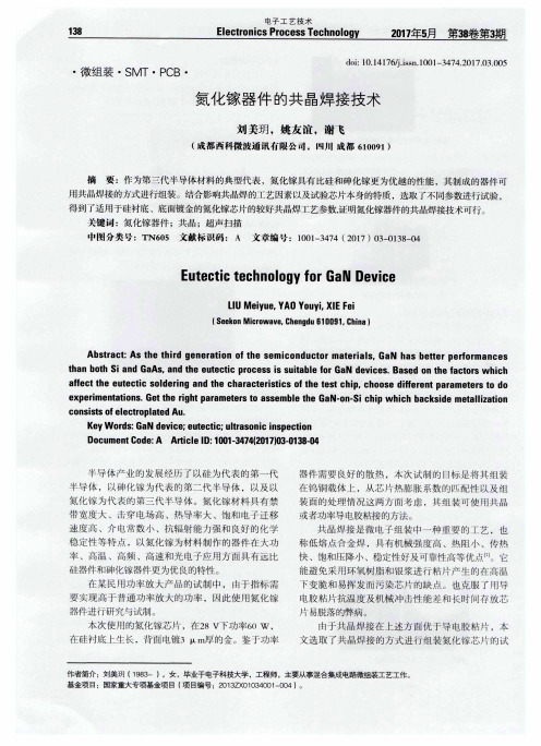
K e y Wo r d s : G a N d e v i c e ; e u t e c t i c ; u l t r a s o n i c i n s p e c t i o n
Ab s t r a c t : As t h e t h i r d g e n e r a t i o n o f t h e s e mi c o n d u c t o r ma t e r i a l s ,Ga N h a s b e t t e r p e r f o r ma n c e s t h a n b o t h S i a n d G a A s . a n d t h e e u t e c t i c p r o c e s s i S s u i t a b l e f o r Ga N d e v i c e s . Ba s e d o n t h e f a c t o r s wh i c h a fe c t t h e e u t e c t i c s o l d e r i n g a n d t h e c h a r a c t e r i s t i c s o f t h e t e s t c h i p , c h o o s e d i fe r e n t p a r a me t e r s t o d o e x p e r i me n t a t i 0 n s . G e t t h e r i g h t p a r a me t e r s t o a s s e mb l e t h e Ga N- o n - S i c h i p wh i c h b a c k s i d e me t a l l i z a t i o n
微波芯片共晶焊接技术研究

微波芯片共晶焊接技术研究(引言):随着无线通信技术的发展,微波芯片在雷达、卫星通信、无线电频率识别等领域得到了广泛的应用。
微波芯片的性能要求高、封装密度大,对共晶焊接技术提出了更高的要求。
本文旨在探讨微波芯片共晶焊接技术的研究与应用。
(主体):一、微波芯片共晶焊接技术概述:微波芯片共晶焊接技术是将芯片与封装基板通过高温下的熔点金属固定在一起,实现电气连接和机械固定的方法。
其中,共晶焊接技术是最常用的一种方法。
共晶焊接采用熔点低于芯片的金属合金作为焊料,通过加热使其在芯片和基板之间形成共晶结构,实现电气连接。
共晶焊接技术具有焊点可靠性高、传导性能优良、成本低等特点,被广泛应用于微波芯片的封装中。
二、微波芯片共晶焊接技术研究:1.材料研究:在微波芯片共晶焊接技术中,选择合适的焊料对焊接质量至关重要。
目前常用的微波芯片共晶焊料有Au-Sn、Au-Ge、Au-In等。
这些金属合金具有低熔点、相容性好、导电性能优良等优点,能够满足微波芯片的封装需求。
2.工艺研究:微波芯片共晶焊接工艺需要控制好温度、压力和时间等关键因素。
温度的选择应考虑焊料的熔点和芯片的耐热性。
热板加热、热风加热和激光加热是常用的加热方式。
压力的选取应保证芯片和基板间的良好接触和导热性能。
时间的控制需根据焊接材料的熔化速度来确定。
此外,焊接过程中的环境条件也需要注意,如控制气氛、避免氧化等。
3.质量控制研究:微波芯片共晶焊接的质量控制主要从两个方面进行,一是焊接工艺参数的控制,二是焊接质量的检测。
通过优化焊接工艺参数,如温度、压力和时间的控制,可提高焊接质量。
焊接质量的检测主要包括焊点形态、焊接强度和导电性能等方面。
通过可靠的质量控制手段,能够确保微波芯片共晶焊接连接可靠,有助于提高芯片封装的可靠性。
(结论):微波芯片共晶焊接技术在微波通信领域具有重要的应用价值。
本文对微波芯片共晶焊接技术进行了概述,并对其在材料选择、工艺研究和质量控制等方面的研究进行了探讨。
微波芯片低空洞率共晶焊接技术研究
微波芯片低空洞率共晶焊接技术研究
微波芯片具有低空洞率和良好的共晶焊接技术是当今微电子技
术发展中非常重要的一环。
根据不断发展的微电子技术应用需要,对于低空洞率和共晶焊接技术有着日益深入的研究。
本文主要介绍了微波芯片低空洞率共晶焊接技术的研究以及其背后原理。
首先,本文介绍了低空洞率的概念及其优点。
低空洞率的概念源于半导体的晶体结构,指的是由晶体结构决定的电子活动程度。
一般来说,低空洞率的晶体结构具有较高的电子活动程度,高电子活动程度的晶体结构可以更快地完成电路的功能。
此外,低空洞率的晶体结构还具有低功耗和少漏电等优点,有利于实现更精细的功能和更高的效率。
其次,本文介绍了低空洞率共晶焊接技术的原理和技术流程。
在共晶焊接技术中,采用特定的溶剂,使微波芯片的晶体结构与两片硅基材料之间的接触表面平滑光洁,从而大大提高了共晶焊接的可靠性。
此外,共晶焊接技术还可以保证高焊接温度,使微波芯片中的晶体结构在接触表面上形成稳定的共晶,有助于实现低空洞率。
综上所述,微波芯片低空洞率共晶焊接技术是当今微电子技术发展中重要的一环,其目的是通过高焊接温度、高接触表面平滑光洁等技术手段,实现低空洞率的晶体结构的共晶,从而达到低功耗、少漏电等要求。
本文分析了低空洞率共晶焊接技术的原理,提高了对该技术的理解和应用,为微电子技术的发展提供了参考和借鉴意义。
- 1 -。
共晶焊原理
共晶焊原理
共晶焊原理【焊接工艺与测试】
共晶焊又称低熔点合金焊接。
共晶合金的基本特性是:两种不同的金属可在远低于各自的熔点温度下按一定重量比例形成合金。
在微电子器件中最常用的共晶焊是把硅芯片焊到镀金的底座或引线框上去,即“金-硅共晶焊”。
众所周知,金的熔点1063℃,而硅的熔点更高,为1414℃。
但是如果按照重量比为2.85%的硅和97.15%的金组合,就能形成熔点为363℃的共晶合金体。
这就是金硅共晶焊的理论基础。
金-硅共晶焊的焊接过程是指在—定的温度(高于363℃)和一定的压力下,将硅芯片在镀金的底座上轻轻揉动摩擦,擦去界面不稳定的氧化层,使接触表面之间熔化,由二个固相形成—个液相。
冷却后,当温度低于金硅共熔点(363℃)时,由液相形成的晶粒形式互相结合成机械混合物金-硅共镕晶体,从而使硅芯片牢固地焊接在底座上,并形成良好的低阻欧姆接触。
共晶焊接工艺
共晶焊接工艺
共晶焊接工艺是一种高温焊接技术,它将两个或多个金属部件焊接在一起。
该工艺的原理是在金属部件的焊点处加热到足够高的温度,使得该点上的金属熔化并形成一种称为共晶的液态合金。
在共晶焊接工艺中,使用的焊接材料通常是含有铅和锡的合金,因为这些材料的熔点较低,易于熔化和混合。
共晶焊接技术广泛应用于电子电路板的制造,因为它可以产生可靠的连接,并且可以保证极小的电阻和电感。
但是,由于铅等有毒物质的使用可能会对环境和健康产生负面影响,因此一些国家已开始寻求使用环保型的焊接材料,例如含有银或铜的合金。
共晶技术资料
共晶技术的热阻更小,毕竟是金属连接1.在生产效率上,哪个更高?银浆工艺时间较共晶长,但银浆操作较共晶简单:——这点不赞同,如果用锡膏也算共晶的话,锡膏作业会减慢作业时间2。
适合大功率、中小功率? 大功率,共晶优势在于减小热阻大功率的最大问题就是散热,毫无疑问,共晶技术散热好3.光效?侧面来说共晶高————因为共晶能更快的散热,而LED发光效率是与热成反比的另外,银胶里面有有机物成分,而这些有机物成分容易老化4.未来发展方向? 共晶—-———对银浆可说是绝对的优势关键字:LED照明LED芯片共晶覆晶LED封装环氧树脂随着手机闪光灯、大中尺寸(NB、LCD-TV等)LED显示屏光源模块以至特殊用途照明系统之应用逐渐增多.末来再扩展至用于一般照明系统设备,采用白光LED技术之大功率(High Power)LED市场将陆续显现。
在技术方面,现时遇到最大挑战是提升及保持亮度,若再增强其散热能力,市场之发展深具潜力。
近年来,随着LED生产技术发展一日千里,令其发光亮度提高和寿命延长,加上生产成本大幅降低,迅速扩大了LED应用市场,如消费产品、讯号系统及一般照明等,于是其全球市场规模快速成长。
2003年全球LED市场约44.8亿美元(高亮度LED市场约27亿美元),较2002年成长17.3%(高亮度LED市场成长47%),乘着手机市场继续增长之势,预测2004年仍有14。
0%的成长幅度可期。
芯片设计从芯片的演变历程中发现,各大LED生产商在上游磊晶技术上不断改进,如利用不同的电极设计控制电流密度,利用ITO薄膜技术令通过LED的电流能平均分布等,使LED芯片在结构上都尽可能产生最多的光子。
再运用各种不同方法去抽出LED发出的每一粒光子,如生产不同外形的芯片;利用芯片周边有效地控制光折射度提高LED取光效率,研制扩大单一芯片表面尺寸(〉2mm2)增加发光面积,更有利用粗糙的表面增加光线的透出等等.有一些高亮度LED芯片上p-n两个电极的位置相距拉近,令芯片发光效率及散热能力提高。
ASM共晶焊分析

粗糙的表面
平滑的表面
选择材料
芯片
– 共晶点 < 支架/陶瓷板 最高可承受的温 度
支架
– 塑胶材料 Tg > 共晶材料的共晶点 – 支架设计
坚固性
– 表面粗糙度 < 共晶材料的厚度
能力及挑战
实例 1: 共晶
– 芯片: 底层镀Sn – 支架镀银; 塑胶材料 Tg ~281°C
能力及挑战
Capability & Challenges
实例 2: 焊剂共晶
– 焊剂的选择
注意焊剂残余物会否对LED有影响
– 焊剂的控制
焊剂点印的份量要一致 焊剂份量不可太多, 否则进回流炉加热时会LED会 浮起, 影响LED跟支架的接触, 影响推力及LED的 位置
能力及挑战
实例 2: 焊剂共晶
Vf 固晶前后分别
(单位: V) Die # 1 2 3 4 5 6 7 8 9 10 固晶前 固晶后 2.11 2.107 2.106 2.102 2.105 2.104 2.102 2.102 2.097 2.096 2.112 2.109 2.108 2.105 2.110 2.108 2.104 2.104 2.099 2.097
材料选择
固晶温度
– 选择Tg 较固晶温度高10°c或以上
E.g. AuSn(282°C) 塑胶 Tg ≥ 330°C 固晶或回流加热最高温度:
315-320°C
E.g. AgSn/ Sn (232°C) 塑胶 Tg ≥ 290°C 固晶或回流加热最高温度:
270°C
DMA 分析
DMA (Dynamic Mechanical Analysis)
浅析真空环境下的共晶焊接
浅析真空环境下的共晶焊接摘要:随着经济和科技的发展,微电子组装水平也在飞速进步,而作为其中重要的焊接工艺的共晶焊接占有重要的地位,对其探讨也具有非常重要的现实意义。
本文结合笔者的实践工作经验,首先对共晶焊接的相关理论进行了探讨,包括共晶焊接的概念、原理以及焊料和设备的选用等,然后对真空环境下影响共晶焊接质量的因素进行了探讨,最后在结合理论分析的基础上,提出了两种在真空环境下改进共晶设备的措施,相信可以为实践提供一定的指导意义。
关键词:真空环境;共晶焊接;共晶设备;影响因素1.引言随着科技的进步,微电子组装向着小型化、高可靠性等方向发展,越来越多的芯片需要使用共晶来实现互联,这无意中对芯片焊接工艺提出了非常高的要求。
而真空环境下的共晶焊接却为解决这种要求带来了曙光,它可以解决大面积薄醒功率芯片的无空洞焊接。
但是笔者经过实践分析后认为,共晶焊接的质量对芯片的寿命及可靠性具有比较大的影响,合理的共晶焊接真空度、保护气氛等可以起到非常好的作用。
因此,值得深入进行探讨。
近些年来,真空共晶技术得到了飞速的发展,在混合集成电路领域得到了前所未有的广泛应用,随着真空环境下共晶焊接技术的推广,其相应的设备也得到了快速发展。
在这种现状下,普通的共晶焊接设备明显不能满足一些高性能和高可靠性芯片的焊接工作,笔者立足于真空环境下共晶焊接质量的影响因素,从改进设备方面来寻求解决之道,以达到提升共晶焊接质量的目的,以提升芯片焊接质量的高可靠性。
2.共晶焊接的相关理论2.1. 共晶焊接概念共晶焊接是一种低熔点的合金焊接,它是指在相对较低的温度下共晶焊料发生共晶物熔合的现象,共晶合金直接从固态变成液态,而不经过塑性阶段。
在对共晶焊接分析时可知,共晶焊料是由两种或者两种以上的若干金属组成的合金。
还有一个概念是共晶温度,它是共晶材料的熔化温度,它往往会受到共晶焊料中合金成分比例的影响。
2.2.选取共晶焊料共晶焊料的选取非常重要,是共晶焊接中比较关键的部分。
- 1、下载文档前请自行甄别文档内容的完整性,平台不提供额外的编辑、内容补充、找答案等附加服务。
- 2、"仅部分预览"的文档,不可在线预览部分如存在完整性等问题,可反馈申请退款(可完整预览的文档不适用该条件!)。
- 3、如文档侵犯您的权益,请联系客服反馈,我们会尽快为您处理(人工客服工作时间:9:00-18:30)。
共晶焊资料(转引)焊接2009-09-02 18:22:56 阅读593 评论0 字号:大中小2007-09-12 09:47:281 引言共晶焊技术在电子封装行业得到广泛应用,如芯片与基板的粘接、基板与管壳的粘接、管壳封帽等等。
与传统的环氧导电胶粘接相比(表1),共晶焊接具有热导率高、电阻小、传热快、可靠性强、粘接后剪切力大的优点,适用于高频、大功率器件中芯片与基板、基板与管壳的互联。
对于有较高散热要求的功率器件必须采用共晶焊接。
共晶焊是利用了共晶合金的特性来完成焊接工艺的。
共晶合金具有以下特性:(1)比纯组元熔点低,简化了熔化工艺;(2)共晶合金比纯金属有更好的流动性,在凝固中可防止阻碍液体流动的枝晶形成,从而改善了铸造性能;(3)恒温转变(无凝固温度范围)减少了铸造缺陷,如偏聚和缩孔;(4)共晶凝固可获得多种形态的显微组织,尤其是规则排列的层状或杆状共晶组织,可成为优异性能的原位复合材料(in-situ composite)。
共晶是指在相对较低的温度下共晶焊料发生共晶物熔合的现象,共晶合金直接从固态变到液态,而不经过塑性阶段。
其熔化温度称共晶温度。
"真空/可控气氛共晶炉"是国际上近几年推出的新设备,可实现器件的各种共晶工艺;共晶时无需使用助焊剂,并具有抽真空或充惰性气体的功能,在真空下共晶可以有效减少共晶空洞;如辅以专用的夹具,则能实现多芯片一次共晶。
我所根据新的工艺要求,研制出2种型号真空/可控气氛共晶炉,如图1所示。
GJL-2023B是PLC(可编程控制器)控制,在温控仪表上设定温度曲线,气体流量控制手动调节。
GJL-225是工控机控制,在液晶显示屏上设定工艺曲线及气体流量等工艺参数,由控制软件自动完成工艺过程。
2 真空/可控气氛共晶炉主要应用领域2.1 IC芯片焊接IC芯片与基板的焊接是共晶焊的主要应用方向。
通常使用金锡(AlaSn 80/20)、金硅(AuSi)、金锗(AuGe)等合金材料的焊片将芯片焊接到基板(载板)上,合金焊片放在IC与基板问的焊盘上。
为了抑制氧化物的形成,通常在IC的背面镀一层金。
以上3种焊料已经被成功地使用于器件进行高温处理,它具有好的机械性能和热传导性。
微波、毫米波电路中,合金焊料通常选用AuSn(熔点280℃)、AuGe(熔点365℃)。
由于2种合金的熔点相差较大,故一般采用AuGe合金将薄膜电路焊接在载板上,再采用AuSn合金焊接微波芯片、电容等元件。
为了避免芯片等元件受到高温热冲击,不少公司采用AuSn合金将薄膜电路共晶到载板上,其他芯片元件采用导电胶焊接的方式。
在多芯片组件中,焊接芯片和基板的材料及组装工艺与混合电路中使用的大致上差不多。
和混合电路一样,在90%/6以上的多芯片模块中使用低成本、易于返修的环氧树脂。
焊料或共晶焊接法主要用于大功率电路或者必须达到宇航级要求的电路。
多芯片组件是当前微组装技术的代表产品,是一种可以满足军用、宇航电子装备和巨型计算机微小型化、高可靠、高性能等方面迫切需求的先进微电子组件。
它将多个集成电路芯片和其它片式元器件组装在一块高密度多层互连基板上,封装在管壳内。
多芯片组件以其高密度、高性能、高可靠性、轻重量、小体积等明显的优势被广泛地应用于航空航天、军用通信和常规武器等军事领域。
多芯片组件在密度不断增加的趋势下还向着大功率、高频的方向发展,而多芯片共晶工艺有助于提高大功率、高频器件的制造技术,适用的夹具有助于提高生产效率,提高成品率,对促进微封装产业的发展具有重要意义。
图2是多芯片样品共晶后的照片及焊接用石墨夹具。
图3是多芯片组件制造的丰要工艺过程示意图。
从此图中可以看出,芯片与基板粘接是成功完成多芯片组件(模块)的关键工艺步骤之一。
目前实现这一步骤的主要工艺有环氧导电胶粘接和共晶焊料焊接2种方法。
虽然导电胶和缘绝胶贴片非常方便,生产率高。
但在微波频率高或功率大时,由于导电胶的电阻率大(100~500μΩ·cm)、导热系数(2~8 W/m·k)小,会造成微波损耗大,管芯热阻大,结温高,影响功率输出和可靠性。
因此对于频率高、功率大的器件,只能采用共晶焊接。
实现共晶焊接的设备有多种,本文介绍的有关共晶焊接的工艺是采用真空/可控气氛共晶炉设备实现的。
使用真空/可控气氛共晶炉进行芯片共晶焊需要注意以下几个方面的问题:2.1.1 焊料的选用焊料是共晶焊接非常关键的因素。
有多种合金可以作为焊料,如AuGe、AuSn、AuSi、Snln、SnAg、SnBi等,各种焊料因其各自的特性适于不同的应用场合。
如:含银的焊料SnAg,易于与镀层含银的端面接合,含金、含铟的合金焊料易于与镀层含金的端面接合。
根据被焊件的热容量大小,一般共晶炉设定的焊接温度要高于焊料合金的共晶温度30~50℃。
芯片能耐受的温度与焊料的共晶温度也是进行共晶时应当关注的问题。
如果焊料的共晶温度过高,就会影响芯片材料的物理化学性质,使芯片失效。
因此焊料的选用要考虑镀层的成份与被焊件的耐受温度。
此外,如焊料存放时间过长,会使其表面的氧化层过厚,因焊接过程中没有人工干预,氧化层是很难去除的,焊料熔化后留下的氧化膜会在焊后形成空洞。
在焊接过程中向炉腔内充入少量氢气,可以起到还原部分氧化物的作用,但最好是使用新焊料,使氧化程度降到最低。
2.1.2 温度控制工艺曲线参数的确立共晶焊接方法丰要用于高频、大功率电路或者必须达到宇航级要求的电路。
焊接时的热损耗,热应力,湿度,颗粒以及冲击或振动是影响焊接效果关键因素。
热损伤会影响薄膜器件的性能;湿度过高可能引起粘连,磨损,附着现象;无效的热部件会影响热的传导。
共晶时最常见的问题是基座(Heater Block)的温度低于共晶温度.在这种情况下,焊料仍能熔化,但没有足够的温度来扩散芯片背面的镀金层,而操作者容易误认为焊料熔化就是共晶了。
另一方面,用过长的时间来加热基座会导致电路金属的损坏,可见共晶时温度和时间的控制是十分重要的。
由于以上原因,温度曲线的设置是共晶好坏的重要因素。
由于共晶时需要的温度较高,特别是用AuGe焊料共晶,对基板及薄膜电路的耐高温特性提出了要求。
要求电路能承受400℃的高温,在该温度下,电阻及导电性能不能有改变。
因此共晶的一个关键因素是温度,它不是单纯的到达某个定值温度,而是要经过一个温度曲线变化的过程,在温度变化中,还要具备处理任何随机事件的能力,如抽真空、充气、排气等事件。
这些都是共晶炉设备具备的功能。
多芯片共晶的温度控制与单芯片共晶不同。
多芯片共晶时会出现芯片材料不同,共晶焊料不同,因此共晶温度不同的情况。
这时需要采用阶梯共晶的方法。
一般先对温度高的共晶焊料共晶,再共晶温度低的。
共晶炉控制系统可以设定多条温度曲线,每条温度曲线可以设定9段,通过链接的方式可扩展到81段,在温度曲线运行过程中可增加充气、抽真空、排气等工艺步骤。
2.1.3 降低空洞率共晶后,空洞率是一项重要的检测指标,如何降低空洞率是共晶的关键技术。
空洞通常是由焊料表面的氧化膜、粉尘微粒、熔化时未排出的气泡形成。
由氧化物所形成的膜会阻碍金属化表面的结合部相互渗透,留下的缝隙,冷却凝结后形成空洞。
共晶焊时形成的空洞会降低器件的可靠性,扩大IC断裂的可能,并会增加器件的工作温度、削弱管芯的粘贴能力。
共晶后焊接层留下的空洞会影响接地效果及其它电气性能。
消除空洞的主要方法有:(1)共晶焊前清洁器件与焊料表面,去除杂质;(2)共晶时在器件上放置加压装置,直接施加正压;(3)在真空环境下共晶。
2.1.4 如伺实现多个芯片一次共晶存进行多芯片组件共晶时,由于芯片的尺寸越来越小,数量越来越多,就必须采用特制的夹具来完成。
这类夹具不但具有固定芯片和焊料位置的功能,本身还要具有易操作、耐高温不变形的特性。
由于有些芯片的尺寸只有0.5 mm2甚至更小,不易定位,人工放置不便,所以共晶炉一般焊接1mm2以上的芯片;在共晶时由于有气流变化,为防止芯片移动,用夹具定位是必需的。
图4、图5、图6是夹具图。
·定位芯片的夹具。
如图4所示;·放置基板的热板;如图5所示;·加压装置。
如图6所示。
夹具除对加工精度的要求外,还须耐受高温且不变形,物理化学性质不会改变、或说其变化不会给共晶带来不利影响、甚至有助于共晶:制造夹具的材料还必须易于加工,如果加工很困难,不利于功能实现。
另外,易于使用也是着要重考虑的方面。
石墨基本附合以上要求,共晶炉的夹具一般选用的就是高纯石墨,它具有以下特点:(1)高温变形小,对器件影响较小;(2)导热性好,有利于热量传播,使温度均匀性好;(3)化学稳定好,长期使用不变质;(4)可塑性好,容易加工。
在一个氧化环境中,石墨中的碳形成CO和CO2,背"擦干"氧气的优点。
石墨是各向同性材料,晶粒在所有方向上均匀、密集分布,受热均匀。
焊接元件被固定在石墨上,热量直接传导,加热均匀,焊接面平整。
2.2 基板与管壳的焊接与芯片和基板的焊接工艺相似,基板与管壳的焊接也是共晶焊很好的应用领域。
在这一工艺中要注意空洞率要符合国军标GJB548-96A的要求,军用产品控制在25%以下。
由于基板一般比芯片尺寸大,且材质较厚、硬些,对位置精度要求低,所以用共晶炉能更好地焊接。
2.3 封帽工艺器件封帽也是共晶炉的用途之一。
通常器件的外壳是陶瓷或可伐等材料外镀金镍而制成的。
"陶瓷封装"在实际应用中由于它容易装配、容易实现内部连接和成本低而成为最优封装介质。
陶瓷能经受住苛刻的外部环境,高温、机械冲击和振动,它是一个刚硬的材料,并且有一个接近硅材料的热膨胀系数值。
这类器件的封装可以采用共晶焊的方法,陶瓷腔体上部有一个密封环,用来与盖板进行共晶焊接,以获得一个气密、真空封焊。
金层一般需要1.5μm,但是由于工艺处理及高温烘烤,腔体和密封环都需电镀2.5μm的金,过多的金用来保护镍的迁移。
镀金可伐盖板可被用来作为气密性封焊陶瓷管壳的材料,在共晶前一般要进行真空烘烤。
共晶炉还可应用于芯片电镀凸点再流成球、共晶凸点焊接、光纤封装等工艺。
除混合电路、电子封装外,LED行业也是共晶炉应用领域。
3 共晶炉与其它共晶设备的比较除共晶炉外,实现共晶焊接的设备还有:带有吸嘴和镊子的共晶机、红外再流焊炉、箱式炉等。
使用这类设备共晶时存在以下问题:(1)在大气环境下焊接,共晶时容易产生空洞;(2)使用箱式炉和红外再流焊炉进行共晶需要使用助焊剂,会产生助焊剂流动污染,增加清洗工艺,若清洗不彻底导致电路长期可靠性指标降低;(3)镊子共晶机对操作者要求高,许多工艺参数不可控,不能任意设置温度曲线,在进行多芯片共晶时,芯片重复受热,焊料多次融化易使焊接面氧化,芯片移位,焊区扩散面不规则,严重影响芯片的寿命和性能。
