MARIS自膨式外周支架系统使用说明201234633420101
Cordis自膨式支架和栓子捕获系统课件
推荐适合血管范围
(N/mm)慢性扩张力Fra bibliotek直径径向支撑力
支架直径
文档仅供参考,不能作为科学依据,请勿模仿;如有不当之处,请联系本人改正。
Biased Stiffness
(N/mm)
慢性扩张力
推荐适合血管范围
径向支撑力
支架直径
直径为10mm的支架在 6mm的血管中的慢性 扩张力
文档仅供参考,不能作为科学依据,请勿模仿;如有不当之处,请联系本人改正。
节段设计确保支架与血管内径的一致性
节段 2mm
连接桥
峰对谷设计
支架弯曲时, 峰对谷设计不 会造成支架突 起,确保最佳 柔顺性
峰
谷
1mm
外展
60°弯曲时
1cm 5 个节段
文档仅供参考,不能作为科学依据,请勿模仿;如有不当之处,请联系本人改正。
Baseline S.M.A.R.T.-design Wallstent
文档仅供参考,不能作为科学依据,请勿模仿;如有不当之处,请联系本人改正。
节段设计确保支架与血管内径的一致性
微网设计: 适合分岔血管
文档仅供参考,不能作为科学依据,请勿模仿;如有不当之处,请联系本人改正。
节段设计确保支架与血管内径的一致性
直径为10mm的支架 在7mm的血管中的慢 性扩张力
直径为10mm的支架 在8.5mm的血管中的 慢性扩张力
文档仅供参考,不能作为科学依据,请勿模仿;如有不当之处,请联系本人改正。
节段设计确保支架与血管内径的一致性
Courtesy of Dr. Skalej, Tübingen
文档仅供参考,不能作为科学依据,请勿模仿;如有不当之处,请联系本人改正。
COOK大支架使用说明书

Zenith®腹主动脉瘤内植入支架产品描述Zenith®腹主动脉瘤内植入支架用于血管内修补肾动脉开口下方的腹主动脉瘤。
它有两套单独的系统可用,一个是分叉系统,另一个是主-单侧髂系统。
支架是自膨式的、标准化的。
支架的主体被事前置于H&L-B One-Shot TM置入系统内。
支架的髂支有各种不同的直径与长度,可选择性与主体的两个髂肢或主-单侧髂的髂支匹配。
适应症Zenith®腹主动脉瘤内植入支架及其置入系统适用于腹主动脉、主髂动脉瘤或髂动脉瘤患者的治疗。
警告●当动脉瘤直径小于40mm时不予治疗,除非有确凿证据表明瘤体快速增长或破裂危险增加。
●不能保证至少一侧髂内动脉开放会增加盆腔器官或肠缺血的风险。
●开放的且不可或缺的肠系膜下动脉可能会导致内漏或盆腔器官或肠的缺血。
●近端瘤颈短于15mm易导致支架的移位。
●近端瘤颈直径大于28mm易产生支架的移位。
●近端瘤颈成角大于60度易产生内漏。
●圆锥形的瘤颈(从肾动脉到动脉瘤上方直径变化超过3mm)易产生支架的移位。
●远端固定部位的髂总动脉直径大于20mm时可能会导致内漏或继续扩张。
●髂外动脉直径小于7mm可能会阻碍置入系统的进入。
●髂总动脉直径小于10mm时可能会妨碍成功的展开和置入系统的进入。
●对不锈钢或聚酯材料过敏不宜置入血管内支架。
●阻碍导丝和置入系统进入的髂股部疾病会妨碍血管内修复的进行。
●有全身感染的患者会增加内支架感染的危险。
●对造影剂过敏时可能会影响支架置入的精确性。
●抗凝不适当会增加出血并发症发生的危险。
●瘤颈部的血栓或钙化会增加移位或肾/远端动脉栓塞的危险。
●股动脉或髂总动脉的严重血栓或钙化会妨碍支架的置入并可能增加远端动脉栓塞的危险。
●临床应用过程中请遵守医疗规程中与这一器械相关的诊疗规定。
●Zenith®腹主动脉瘤内植入支架的置入应在手术室或介入室内应用无菌器械进行,可随时在必要的情况下进行开放性手术。
Hippocampus肾动脉支架系统使用说明201234614350101
肾动脉肾动脉支架系统支架系统(商品名商品名::Hippocampus )使用说明书无菌的,使用环氧乙烷进行灭菌。
仅供一次性使用,不可以重复使用。
在“失效日期”之前使用。
产品目录数字。
批号。
在凉爽,干燥,避光的条件下保存。
请认真地阅读使用说明书。
达到了欧洲指南93/42/EEC中关于医疗器械的要求。
制造商参与了号召节省和再利用外包装的协会。
没有使用橡胶。
无致热原反应。
如果外包装已经打开或者损坏,请勿使用。
仪器名称仪器的商品名是INVATECHIPPOCAMPUSTMRenalStentSystem,仪器的通用名称是肾动脉球囊扩张式支架系统。
描述HIPPOCAMPUSTMRenalStentSystem包括不锈钢的、球囊扩张式支架。
支架是和与之相匹配的球囊一同被预先安装在快速交换支架传送系统(SDS)上的。
在SDS上,球囊近端和远端的下面,有两个不透过X射线的标记,可以协助准确的放置支架。
这一系统适用于肾动脉狭窄性病变的治疗,例如肾动脉开口处狭窄、夹层或者闭塞。
HIPPOCAMPUSTMRenalStentSystem有不同尺寸的可供选择的支架。
额定的支架直径和长度均印刷在接头上。
支架结构球囊扩张式支架是采用激光对不锈钢管AISI316L进行切割而成的。
闭环网格单元设计是以单个网格单元之间的标准连接为基础的,没有尖锐的连接或者焊接点。
而且,我们对支架的设计进行了改进,从而使支架在扩张过程中发生缩短的可能性降到最低,同时也可以实现在肾动脉开口处血管中展开支架的近端。
球囊导管的结构支架传送系统是以快速交换球囊导管的设计为基础的。
快速交换部分只适用于0.014”的导丝。
经过控制的特殊的球囊材料的顺应性可以使球囊能够在不同的球囊压力下达到不同的支架所需要的直径。
在8bar的压力下,每个球囊都能够达到额定的直径和长度。
球囊工作于额定压力和额定破裂压力之间。
在高于额定压力时,所有的支架传送系统都将被扩张到额定尺寸之上,能够达到的最大标准差是±5%。
支架成形术操作规范

脑动脉狭窄的血管内治疗操作规范一、术前准备:1、复习病史、进行物理检查、复习有关的实验室检查,尽可能做出病因学诊断。
2、NIHSS评分,便于手术并发症的及时发现和评价。
3、进行脑CT、MRI、MRA、TCD、DSA检查,对动脉狭窄进行临床分型和LMA分型;进行颈动脉超声检查,评价颈内动脉粥样硬化性斑块的稳定性。
4、有条件的单位可进行CBF的研究,可采用灌注CT、灌注MR、PET、SPECT等进行研究;采用Diamox进行激发试验意义最大,对激发试验异常者,结合临床和有关检查,能判断相应的动脉狭窄是否为“罪犯病变”,并预测支架成形术后能否获得预期的疗效。
5、术前3—7天起抗血小板治疗,阿司匹林300mg和噻氯匹定250mg或氯吡格雷75mg qd。
6、术前1天,请麻醉科会诊。
7、术前2小时起,静脉泵注尼莫地平,以3ml/h(10mg/50ml)起,预防脑动脉痉挛。
视血压情况调整尼莫地平用量,维持血压在110-120/70-80mmHg水平,利用其降压和扩张非缺血区动脉的作用,防止高灌注综合征的发生。
二、颅外段脑动脉狭窄内支架成形术的围手术期治疗和监护1、术前3-7天起,口服抵克力得250mg或氯吡格雷75mg,qd,服用1个月。
2、术前3-7天起,口服肠溶阿司匹林300mg/日,病人若无不适,术后可长期服用。
3、术前2小时起,静脉泵注尼莫地平,3ml/h(10mg/50ml)起,依据血压调整用量。
4、术中采用镇痛、镇静麻醉监护。
5、术中采用TCD监测。
6、术中采用ACT监测,指导肝素使用,成形术前即刻静脉入壶3000-5000单位,然后每小时入壶800-1000单位,维持ACT在250-300秒。
7、术后即刻做NIHSS评价,即刻行CT检查,以除外出血并发症。
8、术后使用肝素3次,每次800-1000单位/小时,再观察3小时,待ACT正常后拔鞘,病人平卧24小时,注意局部情况,监测血压、脉搏、尿量、足背动脉、意识状态、神经功能。
自膨式金属支架封堵主动脉食管瘘的应用
·临床经验·自膨式金属支架封堵主动脉食管瘘的应用探讨陈卓然1,唐庆林2,苏军凯2,张华玉2,张鸣青1,2[摘要]目的探讨胃镜下置入自膨式金属支架封堵主动脉食管瘘的临床应用。
方法采用自膨式金属支架治疗主动脉食管瘘,分析支架的治疗效果及安全性。
结果所有的主动脉食管瘘患者均治愈,随访至今未复发。
结论自膨式金属支架是治疗主动脉食管瘘的简便、快捷、安全有效方法。
[关键词]主动脉食管瘘;金属支架;食管异物[中图分类号]R571[文献标志码]B[文章编号]1672-271X(2012)06-0534-02主动脉食管瘘(aortoesophageal fistula,AEF)是一种极其少见的,预后非常凶险的疾病。
本病诊断有一定的难度,病情进展迅速,抢救成功率低,病死率高[1-2]。
近年来,虽然诊断和治疗技术的不断提高,但病死率无明显下降[3]。
我院2009年7月至2010年12月收治4例AEF,应用自膨式金属支架(self-expanding metal stent,SEMS)封堵AEF,获得成功,现报告如下。
1对象与方法1.1对象4例为男性,年龄40 66岁,平均53.75岁,均为食管异物取出后AEF。
食管异物1例为鸡骨,3例为鱼骨。
部位分别位于距门齿20 cm、20cm、21cm、25cm,分别于吞下异物后6、72、72、72h后就诊。
主要症状:胸骨后及后背部刺痛,吞咽、咳嗽及进食时加重,但无胸闷、气喘、呼吸困难及黑便。
门诊电子胃镜检查确诊食管异物。
1.2术前准备入院后完善术前常规检查、电子胃镜检查、食管CT增强扫描、心电图检查。
嘱患者禁食,卧床休息,勿剧烈活动。
术前予抑酸、补液等治疗,备血并签署手术同意书。
1.3手术方法心电监护下,取左侧卧位,电子胃镜下,予食管异物取出术,见梗卡处食管黏膜充血糜烂,均能成功取出食管异物,迅速再次进镜,见梗卡处食管黏膜活动性涌血,即置入西格玛CZES-II型覆膜自膨式金属支架封堵,压迫止血,要求支架上下端分别超过病变部位2cm左右,覆膜要求完全封堵作者简介:陈卓然(1990-),女,安徽宣城人,硕士研究生,从事消化内科工作作者单位: 1.361005福建厦门,厦门大学预防医学系;2.363000福建漳州,解放军175医院(厦门大学附属东南医院)消化内科通讯作者:张鸣青,E-mail:zmqing8084@sina.com 住瘘口,两端直径较常规支架大,使其可以与食管壁紧密相贴,镜下观察数分钟,未见活动性出血退镜,确保生命体征平稳。
食管癌自膨式食管支架置入术
食管癌自膨式食管支架置入术核心提示:该术式适用:不宜手术的恶性疾病所致的食管狭窄;各种原因引起的食管—气管(或支气管)瘘及顽固性食管良性狭窄等。
该方法能明显改善患者的生存时间和生活质量。
自膨式食管支架是由镍钛合金(Ni—Ti合金)丝编织而成的网状支撑管,又称为镍钛记忆合金支架。
这种支架在治疗因某些原因所致的食管狭窄性疾病和穿孔或瘘形成疾病中具有很高的实用价值。
该术式适用:不宜手术的恶性疾病所致的食管狭窄;各种原因引起的食管—气管(或支气管)瘘及顽固性食管良性狭窄等。
该方法能明显改善患者的生存时间和生活质量。
用覆膜支架治疗食管—气管(或支气管)瘘,其瘘口封闭成功率在95%以上。
方法:1术前准备:空腹8h以上,术前20min咽部局麻,并肌注安定、654-2各10mg以镇静和减少分泌。
2使用器械:Olympus EVIS200型电子胃镜或XQ20型纤维胃镜,岛津500MA X光机,引导钢丝,Savary锥形硅胶扩张器,直径0.5~2cm不等,Microwasivt Ultraflex食管金属支架及其安装系统。
3操作步骤:①定位及选择支架:可根据术前X线片了解食管狭窄的长度和部位,或胃镜直视下观察其狭窄起始端和终末端而确定。
根据狭窄长度,其两端各加2~3cm为原则选择支架长度。
②扩张狭窄部位:先作胃镜检查,找到狭窄口,将导引钢丝自胃镜活检钳道插入,通过狭窄部位到达胃腔,然后配合医师将胃镜徐徐退出而引导钢丝仍留置下。
选择粗细适当的Savary扩张器,将其沿引导钢丝通过狭窄的部位,由小到大至12.8mm或14mm 的扩张器通过为止。
③支架置入:正确定位后,退出胃镜经导丝插入支架安装系统,以最狭窄处为中点,位置正确后,打开安全阀,退出保护性外壳。
此时,外壳遇粘液后自溶,支架开始自行扩张。
术后3天及1周后,分别在X线或胃镜下观察扩张情况。
一般不需禁食,术后当日以流质为宜。
术后并发症1反流性食管炎:患者表现为胸痛、反酸,加用胃肠动力药及粘膜保护剂和抑酸药物后常能缓解。
一种应急自膨式外周动静脉插管及其使用方法[发明专利]
![一种应急自膨式外周动静脉插管及其使用方法[发明专利]](https://img.taocdn.com/s3/m/e8c4d01e0242a8956aece4d4.png)
专利名称:一种应急自膨式外周动静脉插管及其使用方法专利类型:发明专利
发明人:不公告发明人
申请号:CN202010368348.1
申请日:20200501
公开号:CN112472952A
公开日:
20210312
专利内容由知识产权出版社提供
摘要:本发明涉及医疗器械技术领域,具体涉及一种应急自膨式外周动静脉插管及其使用方法。
为解决现有技术在应急情况下,患者出现低血压、低血容量状况时,无法快速建立外周血管通路进行体外循环生命救治的问题。
本发明采用的技术方案包括由穿刺组件和插管组件;插管管体的前端连接有血管覆膜支架,血管覆膜支架的外壁上套设有释放套管,释放套管可沿血管覆膜支架的外壁滑动,所述的释放套管的直径大于插管管体的直径;所述的引导鞘由结构相对称的组件一和组件二扣和于一体形成一端为锥形的空心柱状体结构;插管组件设置于引导鞘内,所述的穿刺针穿设于血管覆膜支架和插管管体内,并两端伸出于引导鞘外,所述的引导导丝穿设于穿刺针内。
申请人:北京嘉维科技开发有限公司
地址:100029 北京市朝阳区北辰西路69路3单元1205室
国籍:CN
更多信息请下载全文后查看。
Enterprise自扩展纤维胶脑血管支架使用说明书
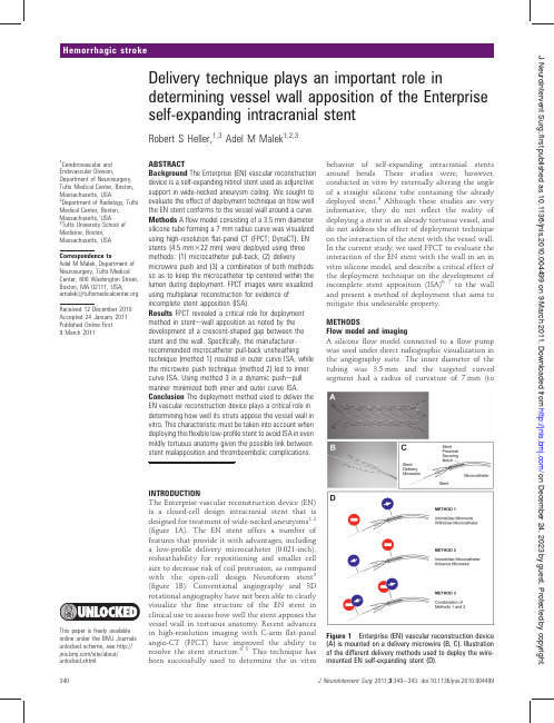
Delivery technique plays an important role indetermining vessel wall apposition of the Enterprise self-expanding intracranial stentRobert S Heller,1,3Adel M Malek 1,2,3ABSTRACTBackground The Enterprise (EN)vascular reconstruction device is a self-expanding nitinol stent used as adjunctive support in wide-necked aneurysm coiling.We sought to evaluate the effect of deployment technique on how well the EN stent conforms to the vessel wall around a curve.Methods A flow model consisting of a 3.5mm diameter silicone tube forming a 7mm radius curve was visualized using high-resolution flat-panel CT (FPCT;DynaCT).EN stents (4.5mm 322mm)were deployed using three methods:(1)microcatheter pull-back,(2)deliverymicrowire push and (3)a combination of both methods so as to keep the microcatheter tip centered within the lumen during deployment.FPCT images were visualized using multiplanar reconstruction for evidence of incomplete stent apposition (ISA).Results FPCT revealed a critical role for deployment method in stent e wall apposition as noted by the development of a crescent-shaped gap between the stent and the wall.Specifically,the manufacturer-recommended microcatheter pull-back unsheathing technique (method 1)resulted in outer curve ISA,while the microwire push technique (method 2)led to inner curve ing method 3in a dynamic push e pull manner minimized both inner and outer curve ISA.Conclusion The deployment method used to deliver the EN vascular reconstruction device plays a critical role in determining how well its struts appose the vessel wall in vitro.This characteristic must be taken into account when deploying this flexible low-profile stent to avoid ISA in even mildly tortuous anatomy given the possible link between stent malapposition and thromboembolic complications.INTRODUCTIONThe Enterprise vascular reconstruction device (EN)is a closed-cell design intracranial stent that is designed for treatment of wide-necked aneurysms 12(figure 1A).The EN stent offers a number of features that provide it with advantages,including a low-pro file delivery microcatheter (0.021-inch),resheathability for repositioning and smaller cell size to decrease risk of coil protrusion,as compared with the open-cell design Neuroform stent 3(figure 1B).Conventional angiography and 3D rotational angiography have not been able to clearly visualize the fine structure of the EN stent in clinical use to assess how well the stent apposes the vessel wall in tortuous anatomy.Recent advances in high-resolution imaging with C-arm flat-panel angio-CT (FPCT)have improved the ability to resolve the stent structure.45This technique has been successfully used to determine the in vitrobehavior of self-expanding intracranial stents around bends.These studies were,however,conducted in vitro by externally altering the angle of a straight silicone tube containing the already deployed stent.4Although these studies are very informative,they do not re flect the reality of deploying a stent in an already tortuous vessel,and do not address the effect of deployment technique on the interaction of the stent with the vessel wall.In the current study,we used FPCT to evaluate the interaction of the EN stent with the wall in an in vitro silicone model,and describe a critical effect of the deployment technique on the development of incomplete stent apposition (ISA)67to the wall and present a method of deployment that aims to mitigate this undesirable property.METHODSFlow model and imagingA silicone flow model connected to a flow pump was used under direct radiographic visualization in the angiography suite.The inner diameter of the tubing was 3.5mm and the targeted curved segment had a radius of curvature of 7mm(toFigure 1Enterprise (EN)vascular reconstruction device (A)is mounted on a delivery microwire (B,C).Illustration of the different delivery methods used to deploy the wire-mounted EN self-expanding stent (D).1Cerebrovascular and Endovascular Division,Department of Neurosurgery,Tufts Medical Center,Boston,Massachusetts,USA 2Department of Radiology,Tufts Medical Center,Boston,Massachusetts,USA 3Tufts University School of Medicine,Boston,Massachusetts,USA Correspondence toAdel M Malek,Department of Neurosurgery,Tufts Medical Center,800Washington Street,Boston,MA 02111,USA;Received 12December 2010Accepted 24January 2011Published Online First 9March2011This paper is freely available online under the BMJ Journals unlocked scheme,see /site/about/unlocked.xhtml on December 24, 2023 by guest. Protected by copyright./J NeuroIntervent Surg: first published as 10.1136/jnis.2010.004499 on 9 March 2011. Downloaded fromcenter of lumen).A calibratedflat-panel biplanar Artis digital subtraction angiography system(Siemens,Malvern,Pennsyl-vania,USA)was used for all procedures.3D FPCT was performed(DynaCT;Siemens)after the deployment procedure using all three deployment methods.Acquisitions were recon-structed and analyzed using the Leonardo software package (Siemens).The FPCT source images were visualized using multiplanar reconstruction and maximal intensity projection using Osirix software(64-bit version 3.8;Pixmeo,Bernex, Switzerland).Deployment methodA standard Envoy5-French guide catheter was used to advance a Prowler Plus Select0.021-inch microcatheter(Codman Neurovascular,Chelmsford,Massachusetts,USA)across the targeted tubing bend over a0.014Agility microwire(Codman). A4.5mm322mm EN stent was advanced underfluoroscopic guidance and centered over the target aneurysm.The stent was then initially deployed using the same technique of immobi-lizing the delivery microwire and unsheathing the stent by withdrawal of the delivery(Prowler Plus Select)microcatheter until theflared ends and distal5e6mm of the stent were in contact with the wall(figure1C).The rest of the deployment was then performed using three distinct methods(figure1D).In method1(microcatheter pull-back),the stent delivery micro-wire was kept immobilized and the rest of the stent was unsheathed by simple withdrawal of the microcatheter (figure1D,T op).Method1is recommended by the manufacturer in its instructions for use(‘If stent positioning is satisfactory, carefully retract the infusion catheter,while maintaining the position of the deliverywire,to allow the stent to deploy across the neck of the aneurysm.The stent will expand as it exits the infusion catheter.’).In method2(microwire push),the delivery microcatheter was immobilized and the stent delivery microwire was advanced to affect the remainder of the stent deployment (figure1D,Center).In method3(balanced push e pull), a combination of methods1and2was used to insure that the tip of the delivery microcatheter remained centered in the middle of the lumen during the entire delivery process (figure1D,Bottom).RESULTSHigh-resolution FPCT imaging revealed a critical role for EN stent deployment technique in its apposition to the tubing wall on the curved test site(figure2).Using the microcatheter pull-back technique(method1),the EN stent tended to follow theFigure2Sagittal thick(3.5mm,A,B,C)and thin(1mm,D,E,F)and axial thin(0.4mm,G,H, I)reconstructions of high-resolutionflat-panel CT in the same silicone model deployed using method1(microcatheter pull-back,A,D,G), method2(microwire push,B,E,H)and method3 (dynamic push e pull,C,F,I).Note gap between the stent struts and inner wall(arrow).on December 24, 2023 by guest. Protected by copyright./J NeuroIntervent Surg: first published as 10.1136/jnis.2010.004499 on 9 March 2011. Downloaded fromcontour of the inner vessel curve,with poor contact on the outer curve(figure2A,D,G).This resulted in the development of significant outer curve ISA,seen as a crescent-shaped gap between the stent and the wall of the tubing.Conversely,using the microwire push technique(method2)resulted in the EN stent following the outer contour of the curve during its deployment,with a consequent crimp on the inner curve and lack of apposition to the wall at that site(figure2B,E,H),leading to inner curve ISA.By examining the tip of the delivery microcatheter during deployment with methods1and2,it appeared that striving for a mid-luminal microcatheter position during the deployment process may alleviate or balance the tendencies of the stent to follow the outer or inner curve contours.Accordingly,the third technique of balanced push e pull is a combination of methods 1and2that aims to mitigate both inner and outer curve ISA. This is achieved by careful monitoring of the microcatheter tip, applying microwire push when the tip is too close to the wall of the inner curve,and conversely pulling back on the delivery microcatheter when the tip is noted to be getting close to the outer curve.This dynamic balancing technique is continued until the entire stent is delivered,resulting in optimized inner and outer curve apposition(figure2C,F,I).DISCUSSIONThis report is thefirst to highlight the critical importance of deployment technique in the performance of the EN self-expanding stent.Despite using the same relatively large radius curvature silicone model,which is less tortuous than a typical carotid siphon,deployment technique resulted in significantly different configurations of the EN stent with the tubing wall leading to the appearance of outer,or inner curve stent e wall malapposition(figure3).The study has limitations as well,in that silicone tubing does not faithfully reproduce the frictional coefficient or the stiffness of a native vessel wall,even though it is likely superior to a rigid glass tubing model.In addition,a methodical analysis of the dependence of stent apposition on deployment technique at decreasing curvature radius or using different EN stent lengths was not performed in the current analysis.4Because of it closed-cell design,it is possible that the EN stent may not be able to completely appose the vessel wall beyond a certain level of tight curvature,regardless of the deployment technique employed by the interventionalist.Rather,the purpose of the current study was to illustrate the phenomenon of deployment method dependence in a very mildly curved vessel,where the inherent closed-cell design property of the EN stent cannot be directlyimplicated as the only source of thefinding.There are a number of points of clinical relevance that can be derived from thefindings described here.First of all,ISA has been shown to be related to short-term and long-term thromboem-bolic complications as well as vessel thrombosis and occlusion in the coronary circulation.7These observations,however,were made in thicker-strut balloon-mounted coronary stents deployed in atherosclerotic vessels,and may not be applicable to the use of the thinner strut EN stent deployed in non-stenotic aneurysm-bearing vessels.Second,a number of reports have implicated the EN stent in early and delayed migration.89It is possible that lack of complete stent apposition to the wall may contribute to this phenomenon in two ways:(1)by decreasing the surface in contact with the vessel wall and making it more likely to migrate as a result of pulsation of the vessel wall(ratchet effect) or(2)by increasing the exposure of stent elements to the higher centralflow velocities,which may increase the stent surfacecross-section exposed to hemodynamic drag and lead to move-ment of the stent over time.The latter effect is unlikely tocontribute to the reported proximal migration,however,because any hemodynamic drag would tend to move the stent downstream.The third implication is related to subsequent navigationthrough the deployed stent under conventionalfluoroscopy.It isfeasible that an advancing microcatheter or microwire may inadvertently enter into the outer or inner region of ISA,whichis not visible under standardfluorography used in neuro-interventional procedures.This could thereby lead to entangle-ment between the microcatheter and the stent struts.Thecurrent study suggests the possible utility of FPCT imaging toevaluate the relative position of the advancing microwire or microcatheter with respect to the deployed EN stent and anyareas of inner or outer curveISA.Figure3Illustration of resulting incomplete stent apposition(ISA)patterns from deployment methods1e3.Microcatheter pull-back(method1)leads to the stent preferentially apposing the inner curveleading to outer curve ISA(A),while the microwire push(method2)leads to the stent apposing the outer curve resulting in inner curve ISA (B).Method3(C)aims to minimize both patterns of malapposition. on December 24, 2023 by guest. Protected by copyright./ J NeuroIntervent Surg: first published as 10.1136/jnis.2010.004499 on 9 March 2011. Downloaded fromIn conclusion,we have demonstrated that the method of deployment of the EN stent plays an important role in deter-mining the way that the stent apposes to the wall and its configuration.This technical dependence should be kept in mind when deploying the device around curved and tortuous vessels in order to minimize the phenomenon of stent crimping,ovalization,incomplete stent apposition,and their potential deleterious clinical impacts.Funding The senior author has received unrestricted research support from Boston Scientific and Codman Neurovascular.Competing interests The senior author(AMM)has received unrestricted research support from Codman Neurovascular and Boston Scientific for unrelated research. Provenance and peer review Not commissioned;externally peer reviewed.REFERENCES1.Higashida RT,Halbach VV,Dowd CF,et al.Initial clinical experience with a newself-expanding nitinol stent for the treatment of intracranial cerebral aneurysms:the Cordis Enterprise stent.AJNR Am J Neuroradiol2005;26:1751e6.2.Mocco J,Snyder KV,Albuquerque FC,et al.Treatment of intracranial aneurysms withthe Enterprise stent:a multicenter registry.J Neurosurg2009;110:35e9.3.Howington JU,Hanel RA,Harrigan MR,et al.The Neuroform stent,thefirstmicrocatheter-delivered stent for use in the intracranial circulation.Neurosurgery2004;54:2e5.4.Ebrahimi N,Claus B,Lee CY,et al.Stent conformity in curved vascular models withsimulated aneurysm necks usingflat-panel CT:an in vitro study.AJNR Am JNeuroradiol2007;28:823e9.5.Benndorf G,Claus B,Strother CM,et al.Increased cell opening and prolapse of strutsof a neuroform stent in curved vasculature:value of angiographic computedtomography:technical case report.Neurosurgery2006;58(4Suppl2):ONS e E380;discussion ONS-E380.6.Radu M,Jorgensen E,Kelbaek H,et al.Strut apposition after coronary stentimplantation visualised with optical coherence tomography.EuroIntervention2010;6:86e93.7.Rathore S,Terashima M,Habara M,et al.Incomplete stent apposition after coronarystent implantation:myth or reality?J Interv Cardiol2009;22:341e9.8.Kelly ME,Turner RDt,Moskowitz SI,et al.Delayed migration of a self-expandingintracranial microstent.AJNR Am J Neuroradiol2008;29:1959e60.vine SD,Meyers PM,Connolly ES,et al.Spontaneous delayed proximal migrationof Enterprise stent after staged treatment of wide-necked basilar aneurysm:technical case report.Neurosurgery2009;64:E1012;discussionE1012. on December 24, 2023 by guest. Protected by copyright./ J NeuroIntervent Surg: first published as 10.1136/jnis.2010.004499 on 9 March 2011. Downloaded from。
外支架操作手册
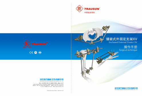
直连接柱 Straight Post
φ5、φ8
04
驰名 商标
镶嵌式外固定支架XV Enchased External Fixator XV
● 抗-旋转星形设计;12种角度插入位置;30°连接柱设计 Anti-rotational star design; 12 location insertion; 30° angled post design
The basic features of Trauson External Fixator XV system were its modular design and the ability to reduce fractures or to make corrections to the alignment of fragments in three planes. Moreover, this system has the same advantage as the previous generation, such as less invasive surgery, simple manipulation, various indications, and application in fractures with severe soft-tissue damage.
近关节固定夹 Peri-Articular Pin Clamp
● 提供更多的框架构型以供选择 Providing wider options of frame constructs
半环形杆 Semi-Circular Curved Rod
(大、中、小) (L,M,S)
● 抗-旋转星形设计;12种角度插入位置;直柱设计 Anti-rotational star design; 12 location insertion; straight post design
Protege GPS自膨式外周血管支架系统
Protege GPS自膨式外周血管支架系统叶宁【期刊名称】《中国医疗设备》【年(卷),期】2015(30)2【摘要】美国ev3公司生产的Protege GPS自膨式外周血管支架系统(Protege GPS Self-Expanding Peripheral Stent System)已于2015年1月21日由FDA 获准进入美国市场。
该产品是一种细长且具有弹性的网状金属管,可植入动脉中向骨盆及下肢供血。
该系统由支架和输送系统两部分组成。
其中的支架部分系一种由钛镍合金制成的植入物,并使用激光将其切割为网状。
使用时需将支架部分置于一根细长型的管状设备——传输导管之中。
【总页数】1页(P157-157)【关键词】支架系统;外周血管;GPS;自膨式;美国市场;支架部分;Stent;输送系统【作者】叶宁【作者单位】【正文语种】中文【中图分类】R732.210.5【相关文献】1.球扩式支架与自膨式支架治疗症状性颅内动脉狭窄的临床效果对比 [J], 柳文科;范雪娟;杨霄鹏2.颅内自膨式支架系统辅助弹簧圈栓塞术治疗颅内宽颈动脉瘤近期疗效观察 [J],刘鹏程;罗有才3.覆膜支架治疗自膨式金属胆道支架植入后迟发性出血1例 [J], 黄鹏;王万胜;印于;杨俊;徐家晨;倪才方4.应用自膨式金属支架缓解恶性结直肠梗阻:系统综述 [J], Watt;AmberM.;Faragher;lan G.;Griffin;Tabatha T.;Rieger;Nicholas A.;Maddern;Guy J.5.EverFlex自膨式外周支架系统—P110023/S007 [J], 任静杰因版权原因,仅展示原文概要,查看原文内容请购买。
Cordis自膨式支架及栓子捕获系统讲课文档
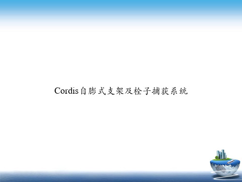
4.8 mm
0.17 cc
0.11 cc
0.0065" (160m) 0.0030"(70m)
ANGIOGUARD RX 11.1 mm 6.17 mm 0.07 cc
0.0040” (100m)
Angioguard是最短的血栓保护装置
快速交换栓子捕获钢丝系统概述
➢ Angioguard RX 180cm快速交换系统 ➢ 快速交换剥脱释放鞘 ➢ 快速交换回收鞘 ➢ 更小的输送外径 ➢ 网篮和导丝结构未改变 ➢ 网篮直径5-8mm
Cordis自膨式支架及栓子捕获系统
优选Cordis自膨式支架及栓 子捕获系统
精确-尽在掌握
➢ 卓越的支架与优秀的输送系统结合 ➢ Precise Rx颈动脉支架具有与Precise支架相同
的绝佳设计
基本设计与Precise支架相同 镍钛合金 一体化激光切割 多节段设计 微网结构
全新快速交换输送系统使手术过程 更加快速\简便
Marker Band
不同滤网设计的贴壁性比较
EPI Filter
MedNova Filter
没有被保护的区域
AngioGuard
100 µm滤网孔径保证血流灌注并有效捕获栓子
EPI Filter EX pores = 80µm
Angioguard pores = 100µm
EPI filter EZ pores
远端标记
滤伞输送器长度缩短至180cm可以减少滤伞移位 => 减少血管壁损伤
释放鞘
极佳的输送性和跟踪性 ➢易通过 ➢减少血管损伤 ➢90cm和100cm处有2个剥脱标记
输送外径减小至 3.4-4.0F
5 mm 3.4 F 6 mm 3.6 F 7 mm 3.7 F 8 mm 4.0 F
自膨胀金属支架在癌性肠梗阻治疗中的临床疗效分析
自膨胀金属支架在癌性肠梗阻治疗中的临床疗效分析赵兴旺;刘正;王锡山【期刊名称】《中国全科医学》【年(卷),期】2016(19)3【摘要】背景结直肠癌是常见的肿瘤,部分患者就诊时已伴有急性完全或不完全性肠梗阻,急诊手术一直是肠梗阻治疗的首选方案,而自膨胀金属支架(SEMS)的运用,使急诊手术转变为择期手术,同时降低了术后并发症和病死率.目的比较行SEMS后序贯择期手术治疗与急诊手术治疗癌性肠梗阻患者的短期疗效,探讨SEMS在癌性肠梗阻中的有效性和安全性.方法回顾性分析2011年9月-2015年4月在哈尔滨医科大学附属第二医院结直肠肿瘤外科治疗的78例结直肠癌伴肠梗阻患者.根据治疗方式将患者分为急诊手术组54例,SEMS组24例.收集患者临床资料,观察患者一期吻合切除率、肠造口率、术中出血量、淋巴结清扫数目、手术时间、美国麻醉医师协会(ASA)分级、平均住院时间、术后排气时间、美国癌症联合委员会(AJCC)术后分期,观察患者术后并发症发生情况.结果两组患者性别、病理类型比较,差异有统计学意义(P<0.05).两组患者年龄、体质指数(BMI)及糖尿病、高血压、心脏病、肝胆系统疾病、呼吸系统疾病发生率比较,差异无统计学意义(P>0.05).SEMS组患者SEMS留置时间为(14.5±5.9)d.SEMS组患者手术时间短于急诊手术组,平均住院时间长于急诊手术组(P<0.05).两组患者一期吻合切除率、肠造口率、术中出血量、淋巴结清扫数目、ASA分级、术后排气时间、AJCC术后分期比较,差异均无统计学意义(P>0.05).两组患者术后并发症发生率比较,差异均无统计学意义(P>0.05).结论 SEMS可安全、有效地应用于癌性肠梗阻的治疗,值得临床推广应用.【总页数】5页(P259-263)【作者】赵兴旺;刘正;王锡山【作者单位】150086 黑龙江省哈尔滨市,哈尔滨医科大学附属第二医院结直肠肿瘤外科;150086 黑龙江省哈尔滨市,哈尔滨医科大学附属第二医院结直肠肿瘤外科;150086 黑龙江省哈尔滨市,哈尔滨医科大学附属第二医院结直肠肿瘤外科【正文语种】中文【中图分类】R735.34【相关文献】1.经肛肠梗阻导管与经结肠镜放置金属支架在低位大肠癌性梗阻治疗中的对比研究[J], 邢喆;赵莹;朱佳;孙婷;高娜;向国卿2.金属支架置入术治疗左侧癌性肠梗阻护理体会 [J], 王葵儿3.经内镜放置金属支架及肠梗阻导管治疗左侧大肠癌性梗阻效果观察 [J], 司令4.经肛肠梗阻导管及自扩张金属支架治疗左半结肠癌性梗阻的研究进展 [J], 徐一;朱莹杰5.自膨胀金属支架后择期手术治疗癌性肠梗阻的疗效观察 [J], 翟红瑞;段宝民;李拥军;罗松平;葛明因版权原因,仅展示原文概要,查看原文内容请购买。
- 1、下载文档前请自行甄别文档内容的完整性,平台不提供额外的编辑、内容补充、找答案等附加服务。
- 2、"仅部分预览"的文档,不可在线预览部分如存在完整性等问题,可反馈申请退款(可完整预览的文档不适用该条件!)。
- 3、如文档侵犯您的权益,请联系客服反馈,我们会尽快为您处理(人工客服工作时间:9:00-18:30)。
(figure 1:图 1; Detail A:细节 A)
第3页共9页
适应症
TM
M a r i s 镍钛记忆金属合金自膨式外周支架系统用于外周血管动脉粥样硬化和 胆道恶性肿瘤患者的姑息治疗。 禁忌症 禁忌症与 P T A有关,包括但不仅限于: - PTA 效果欠佳的高度钙化性病变 - 新鲜的、软的血栓或栓塞物存在 - 有未纠正的出血性疾病病史 - 功能性相关的流入道阻塞、很少的流出道或者没有远端血流 - 在穿孔的胆管上的泄漏处安装支架可能导致病变恶化 - 当并存严重的腹水、广泛的转移性疾病或者肝脏广泛转移肿瘤时,在胆管上 安装支架 警告 - 该器械仅限一次性使用。禁止重新消毒和/或再次使用。再次使用或重新消毒
自膨式外周支架系统 (商品名:MARIS)
使用说明
第1页共9页
Content 内容
环氧乙烷灭菌 一次性使用 在标有“use-before(限用日期)”标识的日期前使用 目录号 批号 阴凉、干燥、避光处保存。 使用前请仔细阅读使用说明书 遵从欧洲关于医疗器具的指导标准 9 3 / 4 2 / E E C
注意:遇到显著阻力时,请勿强行推进。使用 X 线透视检查阻力的原因并采 取治疗措施。必要时撤出支架系统,使用一个新的系统。
2.松弛移动 推进支架系统越过病变区之后,拉回系统,直到病变区的位置包含在末梢和 近端的不透 X 线的标记之间的时候停止。要保证传送系统的轴到患者体外的时候 仍然保持平滑笔直。 警告:患者体外或者体内传送系统轴的松弛,都有可能导致支架的错放,超 出病变区。 3.支架的释放 推进传送系统,直到不透 X 线的标记物的近端和远端都在病变区。松开联结 传送系统内轴和外鞘的 T u o h y -B o r s t 阀。将钢管保持在固定位置,沿着金 属内轴向近身侧末端方向缓慢拉 T u o h y -B o r s t 阀撤出外鞘。当 T u o h y - B o r s t 阀适配器接触近端 L u e r 锁的时候,完成撑开。 注释:在撑开时,近端钢管应保持在固定的位置,同时撤回外鞘,释放支架。 警告:一旦开始撑开,支架就不能再缩回到传送系统中或者二次定位。 4.撤出的操作步骤 支架完全释放之后,小心撤出传送系统,继续将导丝保留在血管内。撤出系 统后进行常规血管造影。 5.释放后支架的扩张 如果支架在病变区内没有完全膨胀,可以根据标准的 P T A 方法在支架内用 球囊进行后扩。用于后扩的 P T A球囊的直径应基本等于参考血管的直径。 6.支架撑开后 应当拍摄支架安装后的血管造影照片。然后移除导丝和血管鞘,并止血。 注:依靠医师的经验和判断,进行适当的手术后药物疗法。
对于任何血管成形术的操作程序来说,患者的准备和消毒是一样的。 伴随的药物疗法应当遵循普遍用于支架安装操作的标准临床草案。 介入应当在血管造影操作室操作,并且在 X-射线控制下进行。应进行血管 造影了解病变区和侧支血流。如果存在血栓,则应该在使用支架之前用标准方法 溶栓。确保入口血管足够通畅,并且在进行介入操作之前已再次打通。 如果有必要进行预扩,就先用一个 P T A 球囊扩张,然后将穿过狭窄部位的 导丝保留在原处。扩张之后,核实血管和狭窄处的尺寸,从而选择正确规格的支 架。 注:对于植入的操作程序,要按照支架系统外包装上的说明,始终使用适当 大小的血管鞘,来保护穿刺点和避免鞘内传送系统的任何过度的摩擦。
镍钛记忆金属材料可以避免支架在血管中变形。当暴露在体温下时,支架会 扩张到它预塑型时的直径。支架被特别设计成使用之前和移植到血管之后具有高 度柔韧性,以及维持血管通畅性的足够的径向支撑力量。支架是采用激光蚀刻的 方法从一根非焊接的镍钛记忆金属管上切下来的。然后,在加热的条件下将支架 扩张到更大的直径,这样就可以确定支架最终的直径。最后,对支架进行电抛光, 以提供一个没有重叠支点的光滑表面。
第7页共9页
自膨式外周支架系统 (商品名:MARIS) 中文使用说明书附页
1.产品名称: 中文名称:自膨式外周支架系统 商品名: MARIS 英文名: Peripheral Self-Expanding Stent System
2. 规格型号:见附页
3.生产企业: Invatec S.p.A.. Via Martiri della, Liberta’7,25030 Roncadelle,Brescia,Italy
第4页共9页
不良反应
TM
与使用 M a r i s 支架有关的并发症和那些与标准 P T A 操作程序有关的并发症 相类似。并发症可能在操作期间或之后的任何时候发生。潜在的并发症可能包括, 但不仅限于: - 死亡 - 急诊 C A B G (冠状动脉旁路移植) - 呼吸停止 - 出血性或血栓性中风 / TIA(短暂性缺血性发作) - 出血或血肿 - 肾功能衰竭 - 冠状动脉缺血 - 心率失常,包括室颤 - 血栓形成和/或栓塞 - 截肢 - 动静脉瘘 - 假性动脉瘤 - 髂动脉痉挛 - 血管损伤,包括穿孔、破裂和夹层 - 血管闭塞、再狭窄或反复狭窄 - 弥散性血管内凝血 - 感染 - 支架移位 / 栓塞 - 肿瘤生长继发支架阻塞 - 药物反应,对造影剂的过敏性反应 - 抗凝 / 抗血小板药物引起的出血 使用说明 操作前
外鞘(6)在近端连接了一个带有 L u e r 接头(7)的 T u o h y -B o r s t 阀 (1)。自膨式外周支架被裹在内轴(3)和外鞘(6)之间。这个空间可以通过 T u o h y -B o r s t 阀上的 Y 形连接体(9)的操作之前冲洗。
在支架释放之前,要完成支架在靶病变区的定位,这就要通过内轴的两个不 透 X 线的标记来指示收缩的支架在传送系统中的位置。要释放支架,就要逆时针 旋转 T u o h y -B o r s t近端阀螺丝(1 0),松开 T u o h y -B o r s t 阀。固定 内轴,相对内轴往后移动外鞘撤去外鞘,支架膨开。
不含乳胶,无热原。如果包装已经打开或破损,请勿使用。
第2页共9页
器泰克公司生产的镍钛记忆金属合金自膨式外周支架系统。
说明
TM
M a r i s 是一种维持外周动脉通畅的自膨式外周支架系统。由镍钛合金(镍 钛记忆金属)构成。在支架的每一端都有一个不透 X 线的钽标记物来提高其在 X 线透视检查下的可见度。
6 F传送系统,如图 1 所示,由一个内轴和一个外鞘组成。内轴(3)在末梢 连接一个无创性软尖(4),这里也是导引钢丝的入口位置;在近端连接一个钢管 (2),这个钢管穿过 T u o h y -B o r s t 适配器并在近端连接一个 L u e r 接头, 这里也是导引钢丝的出口。两个不透 X 线的钽标记物,位于支架一远(1 1)一 近(1 2)的位置,安装在外鞘的内侧。
使用支架的操作步骤 1.系统介绍 用适当的附件进入治疗位点,然后插入一根足够长的 0 . 0 3 5 ’’导丝并穿
过病变区。 警告:系统必须始终沿一根适当的导丝引入、移动或撤出。 如果有必要的话,用一个标准 P T A方法进行预扩张,然后沿 0 . 0 3 5 ’’导
丝通过 6 F鞘将系统导入到达病变部位,导丝是预先穿过狭窄放置并固定好的, 操作应在 X 线透视下进行。
第6页共9页
磁共振成像兼容性
MR Conditional 非临床测试证实 Maris 支架符合 MR Conditional。可在以下条件下安全地进行 扫描:
静态磁场强度在 3T 或以下 空间梯度磁场小于 88T/m
2
静态梯度磁场梯度积小于 201T /m 最大全身平均比吸收率(SAR)1W/kg 进行 20min 扫描
温升:在不高于 3T 的静态核磁共振条件下进行 20 分钟的扫描,全身平均 SAR 不超过 1W/kg 的条件下,支架温升与背景温升之差应不大于 6℃。
伪影:1.5T 条件下核磁共振影像伪影能够对植入物周围环境产生影响。按 ASTM 2119-07 中规定的方法,在不高于 1.5T 的静态核磁共振条件下,支架产生的最 大伪影(支架与伪影边缘间的单边距离)在长度方向应不大于 2mm,在直径方向 应不大于 15mm。 3T 条件下的伪影估计大 2-3 倍。 注:“3T 条件下的伪影估计大 2-3 倍”,该估计基于内部经验。因支架过长,现 有技术条件下无法进行 3T 条件下的伪影测试,故仅基于经验提供 3T 条件下伪影 情况的大致范围。
