飞通FT-8700B型 AIS 操作说明
全版iVMS8700综合安防管理平台说明书
平台简介海康威视iVMS-8700综合安防管理平台是一套“集成化〞、“数字化〞、“智能化〞的平台,包含视频、报警、门禁、访客、巡查、考勤、停车场、可视对讲等多个子系统。
在一个平台下即可实现多子系统的统一管理与互联互动,真正做到“一体化〞的管理,提高用户的易用性和管理效率。
iVMS-8700平台是自主研发的基于SOA系统架构的集成多系统的联网平台,采用先进的软硬件开发技术,满足系统集中管理、多级联网、信息共享、互联互通、多业务融合等需求。
广泛应用于各种领域,满足领域内弱电综合安防管理的迫切需求。
功能特性统一的管理平台平台同时提供了编解码设备管理、存储管理、运维管理、报警管理等根底设备管控功能。
通过优化系统架构,提高系统的整体效能,使平台对视频监控、门禁、停车场、巡查、报警、可视对讲等系统的管理更灵活、更人性化,为用户提供一站式的解决方案。
开放的体系架构iVMS-8700平台基于SOA架构设计,并通过Web Service及接口提供根底效劳,方便与第三方业务系统相互集成;同时系统采用了基于J2EE的企业业务中间件技术,方便对接第三方厂商的设备。
子系统的统一集成对各子系统进展统一的监测、控制和管理,可以兼容视频、一卡通、报警等各个子系统不同类型的通信方式和多种通信格式。
各个系统按照统一的中间件标准接口通过消息效劳与中心平台进展信息交换和控制信令交换。
实现将分散的、相互独立的子系统用一样的环境、一样的软件界面进展集中管理,并可以监控各子系统的运行状况信息。
数字化与智能化iVMS-8700平台利用高效视频编解码压缩技术〔如MPEG-4、H.264、H.265〕,可以在已有的各类数字传输网络上以非常低的带宽占用实现远距离图像传输,而且可通过与计算机技术的结合实现灵活、丰富、广泛的多媒体应用,对图像的观看可以利用计算机、监视器等各种手段,并最终实现系统的高清视频监控。
iVMS-8700平台以网络化传输、数字化处理为根底,以各类功能与应用的整合与集成为核心,实现单纯的图像监控向报警联动、智能手机、行为分析、人流量统计、人脸分析等应用领域的广泛拓展与延伸。
必能信 8700超音波使用手册
2 8700 ADVANCED 塑焊系统的安装
2.1 安装要求 ································································································ 2-1 2.1.1 安装空间 ······················································································ 2-1 2.1.2 环境要求 ······················································································ 2-3 2.1.3 电源输入范围 ·············································································· 2-3 2.1.4 工厂气源 ······················································································ 2-3 2.1.5 气源输入接口 ·············································································· 2-4
AIS简易操作指南
AIS简易操作指南一、AIS是什么?AIS是船舶自动识别系统(Automatic Identification System)的简称,是一种新型助航系统及设备,应用于船与岸、船与船之间的船舶安全导航和通信的重要系统和技术设备。
二、AIS起到什么作用?1、AIS系统的主要作用是船舶避碰。
将船舶的标识信息、位置信息、运动参数和航行状态等与船舶航行安全有关的重要数据,通过VHF数据链路,广播给周围的船舶,以实现对本区船舶的识别和监视。
安装AIS船台航行于长江口水域的船舶能自动识别和信息交流,通过AIS的使用能增强船舶间避免碰撞的措施,为船舶安全航行提供语音和文本通信的有效的途径,增强了船舶的安全航行意识。
2、AIS系统作用于加强海事管理。
海事管理部门对船舶航行的静态和动态信息进行连续的监视和管理。
三、 AIS发展过程及背景(IMO-International Maritime Organization)航行安全分委会第45次会议对修订的海上人命安全(SOLAS-Safety of Life at Sea)公约第五章进行了最后一次审议,修订后的新五章计划于2002年7月1日生效。
按照SOLAS公约(海上人命安全公约)第五章新规则要求所有在2002年7月1日或以后建造的大于等于300总吨航行于国际航线的船舶、大于等于500总吨航行于国内航线的货船和所有客船均须装配AIS设备。
四、AIS设备有哪些分类?Class A 通用船载自动识别设备Class B 适合小型船舶安装AIS设备Class C 基站Class S 搜救飞机及直升机用AIS设备Class N A-to-N(Aids to Navigation)航标AIS设备目前,AIS系统主要包含岸基系统和船舶终端两大部分,船载终端又可以分为A级和B 级两种类型。
中大型商船安装使用的为A级AIS船舶终端,发射功率为12.5W,小型船舶和渔业船舶安装使用的为B级AIS船舶终端,发射功率为2W,显示屏尺寸不小于8寸。
8700使用说明
8700 4.5ROM刷机_系统设置_软件使用教程一、写在教程前面的话本群新更新BB教程,目录如下:01.8700常见型号对比02.BB相关名词解释03.一些常见的问题汇总(新手看看)04.桌面管理器使用教程05.刷机教程06.关于4.2和4.5ROM 的一些说明07.常用第三方软件说明08.winloader使用教程09.8700拆机指导10.手机电话本实现Outlook同11.8700各版本rom&DM下载地址汇总12.8700官方说明书13.黑莓错误代码一览14.小红灯问题的解决办法15.COD模块说明16.BB做调制解调器拖电脑上网17.FreeRange的使用教程18.关于小红锁的问题19.黑莓解网络锁20.未找到为你的设备设计的附加应用程序的问题21.Btalk软件说明不断更新中……………………………………之前也写了不少教程,群里那20多个教程我想没有几个人看完过吧。
我就来说说我的8700刷机和使用的心得和我的一些方法,让大家做个参考。
我在这只想说如果你想参照我的做法,请你仔细看看这个教程。
废话不多说了,开始我的教程。
(下面所说的软件和教程参考都在群网盘里)。
二、准备工作(本文所提到的软件,在群网盘都有下载,找不到的可以用网盘右侧的搜索功能)刷机工具:1. 421_b013的桌面管理器下载地址:/blackberry/74288.html(这里提倡大家用4.2的DM是因为4.2简单方便又能满足87的全部要求)2.刷机ROM 其中114、124、161、174、182的ROM,这几个ROM都是有东亚版的可以直接刷机的。
3. 就是WIPE(“手机格式化工具”),这里要WIPE(格式化)下就是不想以前系统的一些很莫名其妙的问题来对新系统有所影响。
4. 8700瘦身程序。
这个比较安全,能瘦3-5M的空间。
5. 下载常用软件,这里我把我手机装的软件写给大家做为参照。
软件在网盘,找不到的可以用网盘右侧的搜索功能Anyview(电子书软件,也可以解压ZIP压缩文件、播放MP3和歌词)GBBReader(你要是只看TXT的小说,推荐用这软件)AutoLock(自动锁键盘)CallAssistant(来电助手)DxInput(点讯输入法,现在升级为百度输入法了,4.5ROM没有自带拼音,不会五笔的朋友这个就是首选了)FreeRange(RSS阅读工具)GGBOOK3(在线电子书阅读)BTalk(GOOGLE的聊天工具,在电脑端叫Gtalk,在BB上BTalk,也欢迎加入我们的TALK群,群号:bbers@ , 加这好友后输入@join 按“Enter”键发送,就可以在群里聊天了。
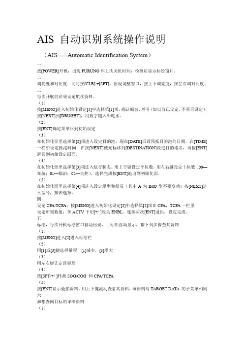
AIS自动安全识别系统操作说明(中文)
AIS自动安全识别系统操作说明(中文)一、操作说明1、3调节显示器亮度和对比度1、同时按[CLR/ALM]+[SFT/+/-]键2、用[ ▲ ]或[▼ ]键调节亮度;用[ ◢ ]或[ ◣ ]调节对比度3、按[ENT]键关闭窗口、1、4 菜单介绍1、4、1菜单操作过程1、按[MENU]键显示主菜单[MENU]*1、TARGET DATA ( 目标数据 )2、 PLOTTER ( 绘图仪 )3、 OWN DATA ( 本船数据 )4、 SET MSG ( 设置短信 )5、 INIT SETTING (6、 SYSTEM SETTING ( 系统设置 )7、 DIAGNOSTICS ( 故障诊断 )[ SYSTEM SETTING ]*1 SET I/O PORT (设置I/O 端口)2 SET CHANNEL (设置频道)3 SET LR MODE (设置远距模式)4 SET OTHER I/O (设置其他I/O)5 SET BUZZER (设置蜂鸣器)2、按相应数字键进入子菜单,例如按[6 ]进入 SYSTEM SETTING 子菜单、(也可以按[ NEXT ] 选择,按[ ENT ] 键进入、3、继续按数字键进入下一级菜单,例如,按[5 ]进入 SET BUZZER 子菜单、[ SET BUZZER ]* ALARM : OFF +/- CPA/TCPA : OFF +/- MSG ALM : OFF +/-4、按[ ENT ] 键保存、5、按[ MENU ]返回主菜单、1、4、2 注意事项确认输入如果修改数据后,未按[ ENT ] 而直接按[ MENU ] 会出现提示CANCEL* YESNO按 YES 不保存退出,如果要保存,选NO ,按[ ENT ],再按[ ENT ] 保存、选择数据输入格式数据输入模式123:数字ABC:字符用[SFT/+/-]切换[ SET MSG]已输入字符数及最大字符数123 0/(151-161)1、5 航行设置航行开始前, INIT SETTINGS 菜单中有5项数据要输入: draught 吃水 destinatuon 目的地 navigation status 航行状态 ship type 船型 number of crew 成员数1、按[ MENU ] 打开主菜单2、按[5 ] 打开INIT SETTINGS 菜单[INIT SETTINGS]*1 SET SHIP DATA (设置船舶数据)2 SET DESTINATION (设置目的地)3 SET NAV STATUS (设置航行状态)4 SET TYPE&CREW (设置船型和成员)5 SET CPA/TCPA (设置避碰距离和避碰时间)6 SET ANTENNA POS (设置天线位置)3、按[1 ] 选择 SET SHIP DATA[ SET SHIP DATA ]* DRUGHT :12、3 mDTE :KEY&DISP +/-1234、选择 DRUGHT (吃水)5、按数字键输入本次航行的准确吃水。
8700B系列数字电参数测量仪
8700B 系列数字电参数测量仪( 8705B 8715B 8706B 8716B 8713 8716C 8716D 8710 )使用说明书版本:ver 2.30 )(青岛青智仪器有限公司.目录述..............................................................................概第一章1第二章主要性能及技术指标 (2)第三章...........................................................................使用说明3扩展接口(打印口、串行口)使用说明第四章 (8)第五章装箱清单 (9)…………………………………………使用注意事项及故障排除方法第六章9第一章概述8705B、8715B、8706B、8716B、8713、8716C、8716D、8710数字电参数测量仪是一种利用数字采样技术对信号进行分析处理的智能型仪表。
测量信号为45Hz~65Hz交流工频信号。
产品符合标准《Q/02。
它的工作过程如下:QZY001-2005 数字电参数测量仪》1.将被测信号转化成适当幅值的电信号;以远大于被测信号的频率将此信号分割成离散信号; 2.利用高速A/D转换器将离散信号转换成数字量; 3.利用微处理器对采集到的数字量进行计算;4.将最终计算的结果以数字的形式显示出来。
5.与传统指针式仪表相比,数字式电参数测量仪具有以下优点:1.所测信号数值为真有效值;直接数字显示,可以减小人为的读数误差; 2.对于波形失真的信号同样适用;3.用一台仪器可以测量多个参数; 4.易于实现智能化,可以与打印机、计算机连接等。
5.数字电参数测量仪广泛应用于家用电器、电机、照明设备等产品的测试以及计量部门。
仪表型号与功能参见表1,用户可以根据使用的具体情况选择性价比最高的仪器型号。
表1:规格型号与功能对照表仪表电压、电流功率参数报警打印电能时间备量程注功能功能累计功率、频率型号因数设置 300V 20A √8705B√ 300V 20A √ 8715B√300V 20A √√可选8706B可选√300V 20A √√√8716B√ 300V 2.5A √√小电流测量√ 8713 可选√√交直流两用可选√√ 8716C 300V 20AHz √)可选 458716D √~300V 20A 1k 宽频,可测(√√ 8710便携式,可扩展电流钳√√300V 20A√√√可选√。
iVMS-8700软件功能说明书
iVMS-8700综合安防管理平台软件技术白皮书目录1. 系统概述 (6)1.1.系统概述 (6)1.2.系统现状分析 (6)1.3.系统需求分析 (7)1.4.平台集成目标 (7)2.系统总体设计 (8)2.1.设计原则 (8)2.2.设计标准 (10)2.3.系统架构 (11)2.3.1.设备接入层 (12)2.3.2.数据交互层 (12)2.3.3.基础应用层 (12)2.3.4.业务实现层 (13)2.3.5.业务表现层 (13)2.4.系统模块 (13)2.4.1.集中管理软件 (13)2.4.2.数据库管理 (14)2.4.3.视频监控管理软件 (14)2.4.4.门禁管理软件 (14)2.4.5.访客管理软件 (14)2.4.6.电梯层控管理软件 (15)2.4.7.在线巡查管理软件 (15)2.4.8.消费管理软件 (15)2.4.9.考勤管理软件 (15)2.4.10.停车场管理软件 (16)2.4.11.可视对讲管理软件 (16)2.5.系统关键技术 (16)3.平台功能 (17)3.1.基础管理功能 (18)3.1.1.平台整体界面 (18)3.1.2.资源管理 (18)3.1.3.视频管理 (19)3.1.4.用户管理 (20)3.1.5.报警管理 (21)3.1.6.地图管理 (24)3.1.7.日志检索 (25)3.1.8.网络管理 (25)3.1.9.系统配置 (25)3.2.基础应用功能 (27)3.2.1.应用客户端整体界面 (27)3.2.2.实时图像的浏览 (27)3.2.3.录像回放与下载 (29)3.2.4.拼控上墙 (31)3.2.5.报警中心 (32)3.2.6.电子地图应用 (33)3.2.7.网络对讲 (34)3.2.8.图片浏览器 (35)3.2.9.视频浏览器 (35)3.2.10.统计查询 (35)3.2.11.系统检测 (36)3.3.可视对讲应用 (36)3.3.1.资源管理 (36)3.3.2.信息发布 (37)3.3.3.权限配置 (37)3.3.4.对讲监控 (38)3.3.5.对讲通信 (38)3.3.6.对讲事件 (41)3.3.7.日志查询 (41)3.3.8.系统配置 (41)3.4.一卡通应用 (42)3.4.1.人员卡片管理 (42)3.4.2.门禁管理 (42)3.4.3.梯控管理 (44)3.4.4.巡查管理 (44)3.4.5.消费管理 (45)3.4.6.考勤管理 (46)3.4.7.访客管理 (47)3.4.8.停车场管理 (48)3.5.高级业务应用 (48)3.5.1.多网域的支持 (48)3.5.2.智能分析联动 (49)3.5.3.流媒体级联功能 (49)3.5.4.手机客户端 (50)3.5.5.数据库备份与恢复 (51)3.5.6.门禁短信开门 (51)3.5.7.接入智盘设备 (51)3.5.8.门禁高级应用 (52)3.6.对外接口模块 (53)3.6.1.BS&CS部分 (53)3.6.2.手机部分 (56)4.平台组成 (56)4.1.中心管理服务器 (56)4.1.1.中心管理服务器 (57)4.1.2.WEB应用服务器 (57)4.1.3.数据库服务器 (58)4.2.功能服务器 (58)4.2.1.流媒体服务器 (58)4.2.2.事件服务器 (59)4.2.3.网管服务器 (59)4.2.4.存储管理服务器 (59)4.2.5.电视墙服务器 (60)4.2.6.门禁接入服务器 (60)4.2.7.通用接入服务器 (61)4.2.8.移动接入服务器 (61)4.2.9.键盘服务器 (62)4.2.10.图片服务器 (62)4.2.11.梯控接入服务器 (62)4.2.12.消费接入服务器 (63)4.2.13.视频接入服务器 (63)4.2.14.行业服务器 (63)4.2.15.可视对讲接入服务器 (64)4.2.16.SIP服务器 (64)4.3.客户端 (64)4.3.1.C/S客户端 (64)4.3.2.B/S客户端 (65)4.3.3.大屏控制客户端 (65)4.3.4.手机客户端 (65)4.3.5.iPad大屏控制客户端 (65)5.平台部署及配置使用 (66)5.1.产品运行环境与数据库配置 (66)5.1.1.软硬件环境 (66)1.1.1软硬件环境 (66)5.1.2.数据库配置 (67)5.2.平台硬件配置 (67)5.2.1.集中管理服务器 (67)5.2.2.存储管理服务器 (68)5.2.3.网络存储服务器 (69)5.2.4.流媒体服务器 (69)5.2.5.事件服务器 (70)5.2.6.电视墙服务器 (71)5.2.7.接入服务器 (73)5.2.8.网管服务器 (74)5.2.9.图片服务器 (75)5.2.10.键盘服务器 (76)5.2.11.移动接入服务器 (77)6.设备接入 (78)7.术语和缩写 (78)8.修订记录 .................................................................................................................... 错误!未定义书签。
AIS数字航标通信管理终端使用说明书
AIS数字航标通信管理终端使⽤说明书AIS数字航标通信管理终端使⽤⼿册⽬录1 产品概述 (2)2 设备的安装及连接 (3)2.1设备连接⽰意图 (3)2.2主机线缆的连接 (3)2.3注意事项 (4)3 功能汇总 (4)3.1航标管理终端的基本功能 (4)3.2太阳能智能化充电管理功能 (5)3.3遥测数据发送功能 (5)3.4遥控指令响应功能 (5)3.5报警功能 (5)4 技术指标 (5)4.1主要技术指标 (5)5 参数配置软件使⽤ (6)5.1串⼝选择 (6)5.2MMSI配置 (7)5.3航标参数配 (8)5.4虚拟航标配置 (9)6 维护与维修 (9)6.1维护 (9)6.2维修和保存 (9)1 产品概述ACTI-AN01数字化AIS航标通信管理终端(以下简称航标管理终端)是以AIS 技术为基础,集成了太阳能智能充电管理功能的新型导航设备。
本设备加装于AIS基站覆盖范围内灯浮、灯船、灯塔等航标设施上,成为航标系统的⼀部分,将航标设施与航标管理部门有机地联系起来,并为航⾏船只提供数字化导航服务。
航标管理终端可与其它AIS设备互通信息,共享整个AIS的VDL链路资源,为船舶、航标、管理部门建⽴了通信联系,为数字化航道建设与其它应⽤功能的开发奠定了基础。
航标管理终端不仅能准确定位,且不受⼤雾、⾬、雪等恶劣天⽓影响,能够将助航信息发送给航道上的船只,使得航标不但可以⽤眼睛观察到,也可以在电⼦海图上显⽰出来,使航标的助航效能提升到⼀个新的层⾯;同时还能及时地把航标灯、蓄电池、太阳能板的状态、灯浮移位和警戒信息发送给管理部门。
该设备的应⽤提⾼了航⾏安全性、⽅便了管理部门对航标设施的管理和维护,将改变传统的航标巡检模式。
航标管理终端设计时参照了如下技术标准或协仪:ITU-R M.1371-3:通⽤AIS技术特性;ICE 62320-2:AtoN设备技术规范;ICE 61162-1/2 Edition 2(NMEA 0183,Version 3.0):海上导航、通信设备及系统数字接⼝标准;ICE 60945 Edition 4:海上导航、通信设备及系统环境要求;ICE 61108-1:海上导航、通信设备及系统——GPS接收机技术规范;产品外观图如图1所⽰:图1 产品外观图2 设备的安装及连接2.1 设备连接⽰意图设备连接⽰意图如图2所⽰:太阳能板航标灯航标管理终端蓄电池图2 设备连接⽰意图2.2 主机线缆的连接航标管理终端对外接⼝由三组电源电缆与⼀组⼯作参数配置电缆组成,连接关系定义如表1~3所⽰。
船载AIS信号无法接收的原因分析及应对建议
船载AIS信号无法接收的原因分析及应对建议邱学刚(杨浦海事局,上海 200090)摘 要:通过AIS设备,船舶和岸台能及时掌握周围水域内所有船舶及动态信息,实现实时互相通话协调,及时采取避让行动,有效保障船舶航行安全。
但是,目前AIS设备使用中存在设备故意关机、数据设置错误、设备故障频发、使用非标设备等诸多问题,导致船载AIS信号无法被其他船台和岸台有效接收,直接影响了AISMarine Technology 航海技术大AIS的安装范围后,国内船载AIS设备的使用在中国迅速普及。
但在船载AIS设备快速普及的同时,部分船舶不按照规定保持船舶自动识别系统处于正常工作状态、不按照规定在设备中输入准确信息等违法行为时常发生。
目前,国内航行船舶AIS设备使用现状乱象丛生,导致他船、公司和海事管理机构等相关方无法及时接收有关船舶AIS信号,这些直接影响着水上交通安全,制约着海事管理的效能。
2 AIS专项检查概况为提高船舶AIS信息准确性、提高海事监管效能、保障船舶航行安全。
自2010年起,交通运输部海事局几乎每年都有针对船载AIS设备监督管理的专题发文,例如,2010年6月开展为期3个月AIS专项检查;2012年将AIS 检查纳入日常监督检查;2014年增加信息输入标准的专项技术要求检查;2015年对船载B级自动识别系统(AIS)新增技术要求;2016年船载AIS设备静态信息固化升级;2017年将 AIS 设备的检查列入国内航行船舶船旗国监督检查和现场监督检查的必查项目,这些发文表明,国内航行船舶船载AIS设备使用不规范的问题突出,岸基无法有效接收部分AIS设备船台信息,系统自动识别船只、协助追踪目标、简化信息交流和提供辅助信息的功能没有充分实现。
杨浦海事局自2017年起,一直将船载AIS设备的检查列入国内航行船舶船旗国监督检查和现场监督检查的必查项目,在辖区持续开展船载AIS设备专项整治。
这期间,专项整治可以分为3个阶段:第一阶段是2017年3月至2018年6月,专项检查的重点是船舶是否开启AIS设备。
AIS自动安全识别系统操作说明(中文)
AIS自动安全识别系统FA-100使用说明一、操作说明1.3调节显示器亮度和对比度1.同时按[CLR/ALM]+[SFT/+/-]键2.用[ ▲]或[▼]键调节亮度;用[ ◢]或[ ◣]调节对比度3.按[ENT]键关闭窗口.1.4 菜单介绍1.4.1菜单操作过程1.按[MENU]键显示主菜单2.按相应数字键进入子菜单,例如按[ 6 ]进入SYSTEM SETTING子菜单.(也可以按[ NEXT ] 选择,按[ ENT ] 键进入.3.继续按数字键进入下一级菜单,例如,按[ 5 ]进入SET BUZZER子菜单.4.按[ ENT ] 键保存.5.按[ MENU ]返回主菜单.1.4.2 注意事项确认输入如果修改数据后,未按[ ENT ] 而直接按[ MENU ] 会出现提示按YES 不保存退出,如果要保存,选NO ,按[ ENT ],再按[ ENT ] 保存.选择数据输入格式1.5 航行设置航行开始前, INIT SETTINGS 菜单中有5项数据要输入: draught 吃水destinatuon 目的地navigation status 航行状态ship type 船型number of crew 成员数1.按[ MENU ] 打开主菜单2.按[ 5 ] 打开INIT SETTINGS 菜单3.按[ 1 ] 选择SET SHIP DATA4.选择DRUGHT (吃水)5.按数字键输入本次航行的准确吃水。
(航行中吃水变化要进行修正)6.按[ ENT ] 确认后返回INIT SETINGS 菜单7.按[ 2 ] 选择SET DESTINATION8.选择DATA ,输入预计到达目的地的日.月,按NEXT 选择TIME9.输入预计到达目的地的时间,按NEXT 选择DESTINATION10.输入目的地的名称,按[ ENT ] 保存后返回INIT SETTINGS 菜单11.按[ 3 ] 选择SET NA V STATUS12. 用[▲] [ ▼] [◢] [ ◣] 在列表中选择相应的航行状态。
中文说明书-船舶自动识别系统
船舶自动识别系统(AIS)中文说明书型号:FA-150按键控制的描述盘①显示屏幕②光标键③菜单键④确认键⑥调节亮度⑤显示键⑦导航状况键⑧开关键开机/关机①按[POWER]键开机/关机按[POWER]键开机/关机。
当开机时, 设备会哔哔几秒钟,然后显示如下:设备确认屏幕开始屏幕图表显示调节面板的对比度和亮度面板的对比度和亮度调节如下:①按DIM]键就会出现以下对话框②使用▼或▲键调节面板亮度; ▼或▲键调节对比度③按[ENT]键,关闭对话框菜单概述你可以从设备中选择功能菜单,如果你不会操作,按[MENU]键,直到你进入主菜单为止,所有的菜单都在菜单列表中1、按下[MENU]键打开主菜单2、使用[CURSORPAD]键选择你想要菜单,然后按[ENT]键3、使用[CURSORPAD]键选择附属菜单,再按[ENT]键,这里有两种类型可供选择,选项和数据登记。
下面的例子就是其中一种选择的类型4、使用▼或▲键,选择你想要的加工项目,按[ENT]键确认5、利用附属菜单选择选项或文字数字的数据选择选项下面的例子就是如何从使用者设置菜单中选择选项A、使用▼或▲键选择想要的项目菜单,按[ENT]键确认就会出现以下窗口选择窗口B、按▼或▲键选择你想要的选择按[ENT]键确认输入文字数字的数据A)选择[DRAUGHT]项,按[ENT]键确认游标B)使用▼或▲键选择适当的数字C)使用键将光标移移到附近的地方,同时按▼或▲键选择数字D)重复C)这一步完成数据输入E)按[ENT]键记录数据6、按[DISP]键关闭菜单设置航程1、按下[NAV STATUS]键打开航行状态菜单2、如果你照旧航行就会展示以下步骤,如果展示相同就可以直接跳到第3步A、按下[ENT]键B、按▼或▲键选择适当的情况并按[ENT]键,涉及的数据可以根据下面选择适当的导航情况3、按键就会显示NAV状态菜单的第2页NAV状态菜单第2页4、 [NEW]项已选择;[按[ENT]键5、按下[ENT]键,使用[CURSORPAD]键输入目的地并按[ENT]键,你可以输入20个字母、数字、符号,和你可以输入20个目的地目的地处理如果您已经登记一些目的地, NAV状态菜单第2页下面如下。
AIS自动安全识别系统操作说明(中文)
AIS自动安全识别系统操作说明(中文)一、操作说明1、3调节显示器亮度和对比度1、同时按[CLR/ALM]+[SFT/+/-]键2、用[ ▲ ]或[▼ ]键调节亮度;用[ ◢ ]或[ ◣ ]调节对比度3、按[ENT]键关闭窗口、1、4 菜单介绍1、4、1菜单操作过程1、按[MENU]键显示主菜单[MENU]*1、TARGET DATA ( 目标数据 )2、 PLOTTER ( 绘图仪 )3、 OWN DATA ( 本船数据 )4、 SET MSG ( 设置短信 )5、 INIT SETTING (6、 SYSTEM SETTING ( 系统设置 )7、 DIAGNOSTICS ( 故障诊断 )[ SYSTEM SETTING ]*1 SET I/O PORT (设置I/O 端口)2 SET CHANNEL (设置频道)3 SET LR MODE (设置远距模式)4 SET OTHER I/O (设置其他I/O)5 SET BUZZER (设置蜂鸣器)2、按相应数字键进入子菜单,例如按[6 ]进入 SYSTEM SETTING 子菜单、(也可以按[ NEXT ] 选择,按[ ENT ] 键进入、3、继续按数字键进入下一级菜单,例如,按[5 ]进入 SET BUZZER 子菜单、[ SET BUZZER ]* ALARM : OFF +/- CPA/TCPA : OFF +/- MSG ALM : OFF +/-4、按[ ENT ] 键保存、5、按[ MENU ]返回主菜单、1、4、2 注意事项确认输入如果修改数据后,未按[ ENT ] 而直接按[ MENU ] 会出现提示CANCEL* YESNO按 YES 不保存退出,如果要保存,选NO ,按[ ENT ],再按[ ENT ] 保存、选择数据输入格式数据输入模式123:数字ABC:字符用[SFT/+/-]切换[ SET MSG]已输入字符数及最大字符数123 0/(151-161)1、5 航行设置航行开始前, INIT SETTINGS 菜单中有5项数据要输入: draught 吃水 destinatuon 目的地 navigation status 航行状态 ship type 船型 number of crew 成员数1、按[ MENU ] 打开主菜单2、按[5 ] 打开INIT SETTINGS 菜单[INIT SETTINGS]*1 SET SHIP DATA (设置船舶数据)2 SET DESTINATION (设置目的地)3 SET NAV STATUS (设置航行状态)4 SET TYPE&CREW (设置船型和成员)5 SET CPA/TCPA (设置避碰距离和避碰时间)6 SET ANTENNA POS (设置天线位置)3、按[1 ] 选择 SET SHIP DATA[ SET SHIP DATA ]* DRUGHT :12、3 mDTE :KEY&DISP +/-1234、选择 DRUGHT (吃水)5、按数字键输入本次航行的准确吃水。
AIS使用说明
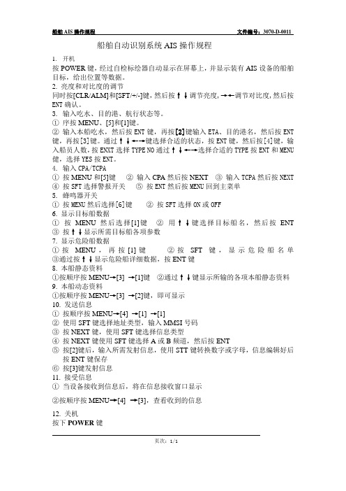
船舶AIS操作规程文件编号:3070-D-0011 船舶自动识别系统AIS操作规程1.开机按POWER键,经过自检标绘器自动显示在屏幕上,并显示装有AIS设备的船舶目标,给出位置等数据。
2. 亮度和对比度的调节同时按[CLR/ALM]和[SFT/+/-]键,然后按↑↓调节亮度,→←调节对比度,然后按ENT确认。
3. 输入吃水、目的港、航行状态等。
①序按MENU、[5]和[1]键。
②输入本船吃水,然后按ENT键,再按[2]键输入ETA、目的港名,然后按ENT 键,再按[3]键。
通过↑↓←→键选择合适的状态,按ENT键,然后按[4]键,输入船员人数,按ENXT选择TYPE NO通过↑↓←→选择合适的TYPE按ENT和MENU 健,选择YES按ENT。
4. 输入CPA/TCPA①按MENU和[5]键②输入CPA然后按NEXT③输入TCPA然后按NEXT④按SFT选择警报开关⑤按ENT然后按MENU回到主菜单5. 蜂鸣器开关①按MENU然后选择[6]键②按SFT选择ON或OFF6. 显示目标船数据①按MENU然后选择[1]键②用↑↓键选择目标船名,然后按ENT③按↑↓显示所需目标船各项参数7. 显示危险船数据①按MENU,再按[1]键②按SFT键,显示危险船名单③通过按↑↓显示危险船详细数据,按ENT键8. 本船静态资料①按顺序按MENU→[3]→[1]键②通过↑↓键显示所输的各项本船静态资料9. 本船动态资料①按顺序按MENU→[3]→[2]键,即可显示10. 发送信息①按顺序按MENU→[4]→[1]→[1]②使用SFT键选择地址类型,输入MMSI号码③按NEXT键,使用SFT键选择信息类型④按NEXT键使用SFT键选择A或B频道,然后按ENT⑤按[2]键后,输入所需发射信息,使用STT键转换数字或字母,信息编辑好后按ENT键保存⑥按[3]键发射信息11. 接受信息①当设备接收到信息后,将在信息接收窗口显示②按顺序按MENU→[4]→[3],查看收到的信息12. 关机按下POWER键页次:1/1。
WF-8700系列电源操作手册说明书
2Reverse Battery ProtectionThe WF-8700 Series Power Centers will charge the 12-volt House battery if installed. A battery DOES NOT have to be installed for WF-8700 Series Power Center converter operation. When a battery is installed, a reverse polarity fuse protects the converter circuitry. The fuse is located along the bottom of the row of fuses. Refer to Figure 1 below. This feature prevents permanent damage to the converter from a battery connected into the circuit backwards. In addition to protecting the converter section, the reverse polarity fuse is the main connection between theconverter and the DC fuse board.3• WF-8712 – 15A (1) • WF-8725 – 30A (1)• WF-8735 – 40A (1)• WF-8740 – 30A (2)Blown Fuse Indicators on DC Fuse BoardThe DC Fuse Board has individual blown fuse indicators as standard equipment. The WF-8712P & WF-8725P have 4 DC circuits (3 Branch and 1 Battery). The WF-8735P and WF-8740P have 6 DC circuits (5 Branch and 1 Battery). Each of the circuits contain a Red LED to indicate a blown fuse. If one of the circuits draws more current than the rating of the fuse, the fuse will blow. When this occurs, the Red LED for that circuit will illuminate. NOTE: The fuse board employs surface mount LEDs which are barely visible to the naked eye. Replace the blown fuse with a known good fuse of the same rating. NOTE: If the replacement fuse blows again, check that circuit for a short or overload condition.Automatic Cooling FanThe cooling fan in the WF-8700 Series Power Center is incremental and is controlled by the current drawn out of the converter to the applied load. NOTE: The WF-8712P does not have a fan. The on-board microprocessor increases fan speed as the total load increases and decreases fan speed as the load decreases. Unlike traditional temperature-controlled fans, the load-controlled fan provides better component cooling by avoiding temperature spikes which can lead to premature component failure.Over-Temperature ProtectionIf the internal temperature of the converter exceeds a critical point, it will shut down. This protects the unit from excessive heat that may damage sensitive components. The unit will restart once the temperature inside has dropped.Electronic Current LimitingIn the event that the output current exceeds the maximum rating for the WF-8700 Series Power Center converter, the output current will remain constant, but the output voltage will begin to drop. If this occurs, the unit will recover once loads are reduced.4Figure 15Short-Circuit ProtectionShould a short-circuit occur in the RV other fault conditions are detected, the converter will resume normal operation. However, short-circuit conditions are dangerous, and an RV will require inspection by a qualified service technician.DC Fuses (12 Volts)The DC fuse boards have spaces the Branch, Battery and Reverse Polarity fuses as described above. Should any of fuses blow, the Branch Circuit fuses and the Reverse Battery Protection fuses should be replaced with ATC or ATO automotive type fuses such as:• Littelfuse type 257• Bussmann type ATCAC Circuit Breakers (120/240 Volts)The AC Breaker side of the WF-8700 Series Power Center is located on the left side of the enclosure. The WF-8700 Series Power Center accepts standard residential breakers. The WF-8712P and WF-8725P have spaces for a 30 Amp Main and up to 3 Branch breakers when using duplex breakers. The WF-8735P and WF-8740P have spaces for a 30 Amp Main and up to 5 Branch breakers when using duplex breakers. A list of factory tested and approved breakers follows. The breakers may be purchased at most big-box department stores and home centers.UL-Listed Main Circuit Breakers, Rated for 120V , Maximum 30A The following breakers have been factory tested and approved for use as 30 Amp Main breakers in the WF-8700 Series Power Center:Manufacturer Model/Cat. No./TypeCutler Hammer Type BR and CThomas Betts Type TB or TBBDITE/Siemens Type QP or QTSquare D Type HOM or HOMTMurray Type MP-T or MH-TGeneral Electric Type THQLUL-Listed Branch Circuit Breakers, Rated for 120V , Maximum 20A The following breakers have been factory tested and approved for use as Branch breakers in the WF-8700 Series Power Center:When replacing any of the installed circuit breakers, the replacement should be of the samemanufacturer, type designation, and equal interrupting rating, not to exceed 30A. The“Short-Circuit-Current” rating for the breaker should be 10,000 Amps.Breaker Filler Plates: Model #FP-01 or FP-01B (Black)Figure 26In order to maximize battery life, it is best to charge batteries slowly, keep them topped off with a trickle-charge when the RV is not being used. The 3-Stage “smart” charger continuously measures the battery voltage output and regulates the amount of charge using three modes of operation; Absorption, Bulk and Float modes.All WFCO power converters are automatic three-stage switching power supplies. The converter senses which mode it needs to be in by checking the RV system voltage.The converter normally provides a constant target output voltage of 13.6 VDC (nominal) to power all the branch circuits. However, it is current limited, and if the output (load) current reaches its maximum, the output voltage will drop as necessary to hold the converter’s maximum output current level (the Amperage rating) without exceeding it. If the output current reaches its maximum (normally caused by a discharged battery), this will cause the converter to go into Bulk Mode, which means the target output voltage will change to 14.4 VDC and a timer will start. Although the converter is outputting 14.4 VDC, you will not be able to read that on a voltmeter due to the voltage-current relationship. From the paragraph above, as load current increases, output voltage decreases. The actual output voltage will not rise until the load current is reduced, which happens naturally as the battery charges or if 12 VDC appliances are turned off. Bulk Mode will be maintained until the current draw drops to approximately five Amps, or until the timer reaches four hours (whichever happens first). Then the target output voltage is changed back to 13.6 VDC for Absorption Mode. Lights that are powered from the output may change brightness slightly at that timNote: For a detailed explanation of the charging modes, please refer to our publication “Theory of Operation”, document #AD-TD-0001-0.Figure 37Before checking the WF-8700 Series Power Center output voltage, disconnect the batterycables at the battery. Make sure the converter is plugged into an AC source (105-130 V AC).Check the converter output voltage at the battery with a voltmeter. Place the meter probeson the discon-nected battery cables; place the Positive (red) meter probe on the + Positivered battery wire and place the Negative (black) meter probe on the - Negative black wire onthe battery cable. Be sure you have good connections at the cables. If the voltage reads 13.6VDC (+/- 0.2) with no load, the converter is functioning properly.If the converter output voltage at the battery reads 0.0 VDC, or if the battery is notcharging, check for an open inline fuse in the battery wire circuit. One may have beeninstalled by the RV manufacturer. Also check for loose wiring connections.NOTE: The battery circuit (Red wire) should have the following fuse installed:WF-8712P – Circuit #4 – 15 AWF-8725P – Circuit #4 – 30 AWF-8735P – Circuit #6 – 30 AWF-8740P – Circuit #6 – 30 AReverse Polarity FusesIf there is no DC output coming from the WF-8700 Series Power Center converter section,first check the reverse polarity fuse(s) on the fuse board. Then, visually inspect the fuses forany breaks in the fuse element. If no breaks are found, use a continuity tester to check forcontinuity. If the reverse polarity fuses are blown, it means the RV battery was accidentallyconnected in reverse, either at the battery or at the converter. Investigate the connectionsand reconnect the cables properly. Replace the fuse with the same type and Amperagerating as the original.IMPORTANT: These fuses protect the converter from damage in the event that the RVbattery is accidentally connected in reverse. A reversed battery connection, even if for onlya second, will cause these fuses to blow.If the above checks have been made but the converter output still reads 0.0 VDC, theconverter is not functioning properly. Contact the Arterra Distribution Power PROs at1 (877) 294-8997. Before placing the call, please have available the WF-8700 Series PowerCenter model number from the front panel label and the 14-digit serial number from thebar code tag located on the fan panel. The fan panel is accessible after the door assembly hasbeen removed.8Should it be determined that the converter section of the WF-8700 Series Power Center is defective, and the unit is under warranty, the entire unit will need to be returned. The converter section is not user serviceable.When preparing the unit for return, remove the AC breakers. Label and disconnect each wire as they are removed from the breakers and Ground and Neutral bars. The DC wires protruding from the back of the WF-8700 Series Power Center have been connected to the DC circuits in your RV by the RV manufacturer. In a similar fashion, label and disconnect these wires. Follow the packaging instructions in your warranty claim packet.GENERAL COMPLIANCE INFORMATIONAgency ListingsULThe WF-8700 Series Power Centers are UL-Listed, and cUL-Listed (Canadian).FCC Compliance Class BNOTE: This equipment has been tested and found to comply with the limits for a Class B digital device, pursuant to Part 15 of the FCC Rules. These limits are designed to provide reasonable protection against harmful interference when the equipment is operated in a commercial envi-ronment. This equipment generates, uses, and can radiate radio frequency energy, and if not installed and used in accordance with the instruction manual, may cause harmful interference to radio communications. Operation of this equipment in a residential area is likely to cause harmful interference in which case the user will be required to correct the interference at his own expense.Figure 49Mounting the EnclosureThe WF-8700 Series enclosure should be mounted in an accessible area such as a wall or in theside of a cabinet. The front of the enclosure should not be obstructed to allow free air flow forthe cooling fan. NOTE: The WF-8712P does not have a fan. The enclosures will slide into roughopenings as follows:• WF-8712P and WF-8725P – 10 7/16” W x 6 1/8” H x 3 ¾” D• WF-8725P and WF-8735P – 10 3/8” W x 6 7/8” H x 4 5/16” DAfter wiring is completed, the enclosure fastens to the wall or cabinet using 4 wood screws (notsupplied).Wiring the AC BreakersMake sure no AC power is coming into the RV from either the Shore Power cord or an on-board generator. Determine the proper size breakers for the loads the WF-8700 Series PowerCenter will be powering. Y ou can use either single or duplex breakers, or a combination of both.We recommend that all the breakers used be of the same brand. A total of 4 breakers can bemounted in the WF-8712P and WF-8725P when using duplex breakers: 1 Main breaker and upto 3 Branch breakers. A total of 6 breakers can be mounted in the WF-8735P and 8740P whenusing duplex breakers: 1 Main and up to 5 Branch breakers. Refer to the tables on pages 5 and 6for a selection of approved breakers. The Main breaker should be 30 Amp and is to be installedin the left-most position. See the wiring diagrams below. A hold down clip is provided to keepthe breaker securely in place.The 30 Amp power cord is routed through the large knockout in the back of the wiringcompartment and secured with a Romex clamp. The Black (Hot) wire is connected to the 30Amp Main breaker as shown. The White (Neutral) wire is connected to the Neutral Terminal barat the bottom of the wiring compartment. The Green (Ground) wire is connected to the GroundTerminal bar also located at the bottom of the compartment.Route the Romex leads for the Branch circuits through the Strain Reliefs in the back of thewiring compartment. In a similar fashion, connect the Black wire to the Branch breaker and theWhite and Green wires to the appropriate Terminal bar.The Black power wire for converter power on the WF-8735P and WF-8740P has a pigtailconnection. The metal pin is inserted in the Branch breaker designated for converter power.The end with the wire nut can be used to power another circuit if necessary. If not used, leavethe wire nut installed and push the wire to the side. Make sure all terminals are torqued to thespecifications listed on the back of the door assembly.10Wiring the DC Fuse BoardMake sure the house battery is disconnected before beginning the DC wiringwhat DC loads are to be connected to the fuse board and what position they will occupy. All4 circuits on the WF-8712 and WF-8725 Power Centers have up to 20 Amp ATO or ATCfuses installed. On the WF-8735 and WF-8740 Power Centers, circuits F5 and F6 can beused for slide-outs or other higher current loads and can have a maximum 30 Amp ATO or ATC fuse installed. The remaining 4 circuits are general purpose and can have up to 20 Amp ATO or ATC fuses installed. Make sure the fuses are seated properly.Figure 511Connect the heavy wire (Red) coming from the battery to the Red 10AWG wire coming fromthe back of the enclosure.As a last step, install a separate bus bar in a location behind the converter. Connect the 10AWGWhite wire coming from the back of the enclosure to this bus bar. Connect the battery negativewire to this bus bar along with all the negative DC load wires. Also, run a wire from the bus barto chassis ground.Figure 61213WFCO extends, to the original owner, a Two Year Limited Product Warranty. This warranty is in effect from the date of original purchase for a period of two (2) years. This limited warranty is extended specifically for and is limited to Recreational Vehicle application and is only valid within the continental United States, Alaska, Hawaii and the Provinces of Canada. WFCO warrants, to the owner, that its products are free from defects in material and workmanship under normal use and service based on its intended use and function. This warranty is limited to the repair or replacement, at WFCO’s discretion, of any defective parts or defective assembly. Any implied warranties of merchantability or fitness for intended use are limited in duration unless applicable State Law provides otherwise. You may have other rights as specified by each individual state.EXCLUSIONS and LIMITATIONSThe OEM warranty specifically does not apply to the following:• Any WFCO product that has been repaired or altered by an unauthorized person; • Any damage caused by misuse, faulty installation, testing, negligence, accident or any WFCO product installed in a commercial vehicle;• Any WFCO product, whose serial number has been defaced, altered or removed; • Any WFCO product, whose installation has not been in accordance to the WFCO written instructions; • Any consequential damages arising from the loss of use of the product including but not limited to: inconvenience, loss of service, loss of revenue, loss or damage to personal property, cost of all services performed in removing or replacing the WFCO product. Specifications are subject to change without notice or obligation.• Any WFCO Electronics products sold through unauthorized Internet sources (Example: eBay) will be excluded from all warranty coverage offered by Arterra Distribution / WFCO. CONSUMER W ARRANTY CLAIM PROCEDUREUpon determination and validation by an authorized OEM dealer that a WFCO product has a defect, a Return Goods Authorization (RGA) number will be required before the product can be returned. The RGA number can be requested by completing the Warranty Information Fax Sheet and appropriate Troubleshooting Form found at . Once these forms have been completed, email the forms along with Proof of Purchase to ***************************************************************************(574) 294-8698. After receipt of the forms, an RGA number will be issued. This number shall appear on all correspondence with warranty service. Upon validation of the warranty, WFCO shall replace the product with a like product. The RGA number shall be placed on the outside of the carton used to return the product for ease of identification. Do not mark directly on the product. The product must be packaged properly to avoid further product damage which could cause a non-warrantable condition.W ARRANTY ASSISTANCEThe consumer may contact the selling Dealer or OEM for warranty assistance. The consumer may also contact Arterra Distribution, exclusive distributor to WFCO Products at: (574) 294-8997 or Fax (574) 294-8698.Figure 7 14Figure 815W F C O E L E C T R O N I C S.C O M。
AIS使用及操作教学学习教案
第十页,共39页。
AIS操作性能(xìngnéng)及要求
● 主 动 、 连 续向他 船或岸 台自动 发送本 船的静 态和动 态信息 。 ● 能 接 收 特 定的轮 询呼叫 ,传输 附加的 安全信 息,并 进行处 理 。 ● 能 在 航 行 中或锚 定(máo dìnɡ)状 态 下 连续运 行。 ● 船 舶 识 别 :应采 用适当 的海上 移动服 务实体 号码( MMSI) 。
通知要求:
1、现阶段ECS设备要求 2000总吨以上的“四客一危”船舶在2011
年6月30日之前安装,对于未按要求配备设备的船舶一律要求开航(kāi
háng)前纠正,复查合格后方可签证放行。
2、现阶段AIS设备要求100总吨以上的所有船舶在2011年12月30日
之前安装(液货船无吨位限制,一律安装),对于未按要求配备设备的
第7页/共39页
第八页,共39页。
AIS通信(tōng xìn )技术
AIS系统是海上移动VHF波段采用TDMA技术交换数据的一种避 碰系统,该系统在161.975MHz和162.025MHz的两个频点即海上 VHF87B/88B频道上收发(shōufā)信号,并合成全球定位系统、电罗经 及自动舵、雷达、电子海图等数据按需要在显示器上显示船位、动态 等信息。
的目标船只
第22页/共39页
第二十三页,共39页。
画面及显示(xiǎnshì)功能
设备采用真彩色液晶显示屏,方便大角度 观察,有海图屏、电子罗盘屏、卫星状态 屏,连续按翻页键可以实现他们之间的转 换。
海图屏
海图屏可以显示全中国的海域及部分内 河(nèihé)流域电子地图,并可实现多级缩 放及任意移动和旋转海图,还可以实时显 示船只的当前位置第、23页速/共39页度、航向、渔区号; 目的地(或游标)所在位置、渔区号、目
iVMS-8700综合安防管理平台说明书
平台简介海康威视iVMS-8700综合安防管理平台是一套“集成化”、“数字化”、“智能化”的平台,包含视频、报警、门禁、访客、巡查、考勤、停车场、可视对讲等多个子系统。
在一个平台下即可实现多子系统的统一管理与互联互动,真正做到“一体化”的管理,提高用户的易用性和管理效率。
iVMS-8700平台是自主研发的基于SOA系统架构的集成多系统的联网平台,采用先进的软硬件开发技术,满足系统集中管理、多级联网、信息共享、互联互通、多业务融合等需求。
广泛应用于各种领域,满足领域内弱电综合安防管理的迫切需求。
功能特性统一的管理平台平台同时提供了编解码设备管理、存储管理、运维管理、报警管理等基础设备管控功能。
通过优化系统架构,提高系统的整体效能,使平台对视频监控、门禁、停车场、巡查、报警、可视对讲等系统的管理更灵活、更人性化,为用户提供一站式的解决方案。
开放的体系架构iVMS-8700平台基于SOA架构设计,并通过Web Service及http接口提供基础服务,方便与第三方业务系统相互集成;同时系统采用了基于J2EE的企业业务中间件技术,方便对接第三方厂商的设备。
子系统的统一集成对各子系统进行统一的监测、控制和管理,可以兼容视频、一卡通、报警等各个子系统不同类型的通信方式和多种通信格式。
各个系统按照统一的中间件标准接口通过消息服务与中心平台进行信息交换和控制信令交换。
实现将分散的、相互独立的子系统用相同的环境、相同的软件界面进行集中管理,并可以监控各子系统的运行状况信息。
数字化与智能化iVMS-8700平台利用高效视频编解码压缩技术(如MPEG-4、H.264、H.265),可以在已有的各类数字传输网络上以非常低的带宽占用实现远距离图像传输,而且可通过与计算机技术的结合实现灵活、丰富、广泛的多媒体应用,对图像的观看可以利用计算机、监视器等各种手段,并最终实现系统的高清视频监控。
iVMS-8700平台以网络化传输、数字化处理为基础,以各类功能与应用的整合与集成为核心,实现单纯的图像监控向报警联动、智能手机、行为分析、人流量统计、人脸分析等应用领域的广泛拓展与延伸。