PZGLI007-品质管理-焊缝射线检测底片评定表
射线无损检测底片评定制度
射线无损检测底片评定制度1.射线无损检测评片按JB4730-94《压力容器无损检测》标准,焊缝射线透照检测中相关要求执行。
2.射线无损检测底片评定、审核工作必须由射线Ⅱ级资格人员担任。
3.评片人员必须了解被检工件的焊接种类、焊接方法、坡口型式以及材料种类等,以提供评片时参考。
4.评片应在专用评片室内进行。
评片室内的光线应暗淡,但不全暗,室内照明用光不得在底片表面产生反射。
5.评片时,底片应在干燥后观察,观察应在光线暗淡的评片室内进行,观片灯应有观察片最大黑度为3.5的最大亮度。
6.评片的底片质量应符合下列要求:6.1底片上必须显示出与透明厚度相对应的要求达到的最小像质指数;6.2底片有效评定区域内的黑度应满足1.2~3.5的要求。
6.3底片上象质计影象位置应正确,定位标记和识别标记齐全,且不掩盖被检焊缝影象。
在焊缝影象上,能清晰地看到长度小于10mm的象质计金属丝影象;6.4在底片评定区域内不应有以下妨碍底片评定的假缺陷;6.4.1灰雾6.4.2处理时产生的条纹、水迹或化学污斑等缺陷;6.4.3划痕、指纹、脏物、静电痕迹、黑点或撕裂等;6.4.4由于增感屏不好造成的缺陷。
6.5对上述不符和底片质量要求的底片应拒绝评定,并要求重拍。
6.6评片人员根据底片上全影象,按JB4730-94《压力容器无损检测》标准中,焊缝射线透照缺陷等级评定的规定进行评定,缺陷评定应坚持:定性(定缺陷特性);定量(定缺陷的大小尺寸和数量);定位(定缺陷所处位置);定级(按JB4730标准评定质量等级)的四定原则。
6.7焊缝无损检测底片评定合格,开出无损检测合格通知单,出具射线无损检测报告,不合格焊缝开出焊缝返修通知单,按相关规定要求返修后复拍再重新评定。
6.8报告及验收标记6.8.1报告至少应包括以下内容:6.8.1.1委托部门、被检工件名称、编号、被检工件材质、母材厚度;6.8.1.2检测装置的名称、型号、透照方法及透照规范,透照部位及无损检测。
PZGLI007-SPC与制程能力评估
3. 制程变异的原因
普通原因: 是造成随着时间推移具有稳定的且可重复的分布 过程中的许多变差的原因, 我们称之为“处于统计控制状态”、 “受统计控制”, 或有时简称“受控”, 普通原因表现为一个稳定 系统的偶然原因. 只有变差的普通原因存在且不改变时, 过 程的输出才可以预测.
特殊原因: 是造成不是始终作用于过程变差的原因, 即当它们 出现时将造成过程的分布改变. 除非所有的特殊原因都被查 找出来并且采取了措施, 否则它们将继续用不可预测的方式 来影响过程的输出. 如果系统内存在变差的特殊原因, 随时间 的推移, 过程的输出将不稳定.
● ●●● ●● ●
例子
對產品 的影響 是否值得 追查原因
同一人使用同一儀器于不同時 間量測產品之差異\不同方向不 同位置測量軸徑\原材料重量\气 候、环境的微小变化\合格原料 的微小变化\机械的微小震动\刀 具的微量磨损
微小, 不明顯
不值得
生產條件設定錯誤\使用不合格材料 加工\機器差異\材料之不同\设备调整 不当\新手违背操作规程作业\刀具过 量磨损\加工方法的改变
1.3.3. 1939年Shewhart與戴明合寫了“品質觀點的統計方法”; 1.3.4. 上世纪40年代期间, 战时生产使该理论得到广泛的应用; 1.3.5. 1950年戴明到日本講學, 介紹SQC觀念及方法, SQC是
發現問題才解決, 浪費較大, 後來發展出了SPC; 1.3.6. 美國汽車業廠商對SPC非常重視, 並使之得到廣泛應用; 1.3.7. ISO9000也十分重視SPC的應用, 對其有專門章節要求.
項目
普通原因
特殊原因
定義 影響
不可避免之原因, 非人為原因, 可避免的原因, 人為原因, 特殊原因,
PZGLI007-品质管理-磁芯检验标准指导书
7.0附件:表一
2
毛刺
1、不超过0.1mm及产品极限尺寸。
2、不影响电气性能指标。
1、超过0.1mm或产品极限尺寸。
2、影响电气性能指标。
3
掉块缺损
1、接触面、正面不超过一处,产品尺寸≤10mm的,最大面积≤0.6mm2,产品尺寸>10mm的,最大面积≤1.0mm2,深度均为≤0.3mm2。
2、侧面不超过两处,产品尺寸≤10mm的,最大面积≤1.0mm2,产品尺寸>10mm的,最大面积≤2.0mm2,深度均为≤0.5mm2。
4.DR型,T型,铁芯实际试做,依我公司规定的圈数测试其电感要符合要求.
5.要测试铁芯的Q值,是否异常.
LCR测试仪
DR,R,T形20个/每批
其它按正常抽验
●
●
●
●
●
5
机械强度测试
磁心在外加载力作用下出现裂纹或断裂时,外加载力大于M强度值时则判定OK,外加载力小于或等于M值时则判定NG。具体检验操作方法见《磁芯强度检测操作规范》。
6.2.4.2检验要求:
取样标准
MIL-STD-105ELEVEL=II允收水准(AQL): MI=0.65 MA=0 .4 CR=0
序号
检查项目
检验标准
工具
抽样测定
缺点等级
CR
MA
MI
1
外观检查
1.磁芯外观不能有破损的现象。
2.磁芯不能出现变形,龟裂之异状。
3.表面须平整光滑清洁,不能有杂物。
4.磁芯接合处不能有磁粉以及其它杂质。
外加载力小于或等于M值时则判定NG。
6
其它不良
1、 外箱唛头标识内容及产品型号与来料相符。
焊缝质量检验级别表

公差
标准公差
图纸尺寸
公差
标准公差
图纸尺寸
公差
标准公差
图纸尺寸
公差
标准公差
质检员
签名
日期
有疑点时,用X射线透照复验,如发现有超标缺陷,应用超声波全部检验
3
外观检查
全部
检查外观缺陷和几何尺寸
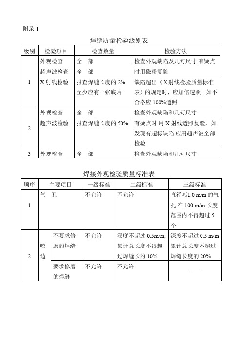
焊接外观检验质量标准表
顺序
主要项目
一级标准
二级标准
三级标准
1
气孔
不允许
不允许
直径≤1.0 m/m的气孔,在100 m/m长度范围内不得超过5个
2
咬
边
不要求修磨的焊缝
不允许
深度不超过0.5m/m,累计总长度不得超过焊缝长的10%
大样检验评定结论:
质保部经理/日期:
《尺寸检验记录表》
工程名称:
构件简图:
构件编号
标号
L
L1
L2
L3
L4
L5
L6
L7
L8
L9
L10
L11
L12
L13
L14
L15
图纸尺寸
公差
标准公差
图纸尺寸
公差
标准公差
图纸尺寸
公差
标准公差
图纸尺寸
公差
标准公差
图纸尺寸
公差
标准公差
图纸尺寸
公差
标准公差
图纸尺寸
公差
标准公差
附录1
焊缝质量检验级别表
级别
检验项目
检查数量
检验方法
1
外观检查
全部
检查外观缺陷及几何尺寸,有疑点时用磁粉复验
超声波检查
PZGLI007-品质管理-生产计划与控制优化

二、生产单位专业化原则和形式
生产单位专业化原则是指对生产过程中的劳动分工与协作关系所作出的 专业化规范,它决定着生产过程的工艺流向、原材料与再制品的运输路线和 运输量。
生产计划与控制
参考书籍
《机械工业企业生产管理学》 马天超主编,机械工业出版社
《生产计划与控制 》 李怀祖 主编,中国科学技术出版社
《生产计划与控制》 王丽亚主编,清华大学出版社
一、生产与生产管理
(一)生产 物质资料的生产是人类赖以生存和发展的基础与条件,是人
们为了满足社会需求创造产品和提供服务的有组织的活动。 从现代经济发展角度讲,凡是将所投入的生产要素转换成有
三、生产系统类型
3、根据产出的有型性划分: (1)服务业生产系统; (2)制造业生产系统; (3)产品与服务一体化生产系统。
注:制造业和服务业的差异
(1)产出的型态方面:制造业产品是有形的,而服务业产品是无形的,不可 触知的。
(2)产出的储存性方面:制造业的产品可以存储,而服务业的产出必须符合 客户的个性化需求,其产出不能存储。
一、制造业生产单位的组成
所谓生产过程的空间组织指在各生产单位或设施内部,对机械设备、运 输装置等进行合理的平面布置与立体布置。
1. 基本生产部门: 指直接从事企业基本产品生产,实现基本生产过程的生产单位。
对大型机械工业企业而言,包括: (1)准备车间:包括铸造、锻压、备料车间等; (2)加工车间:包括机加冲压车间、热处理、电镀车间等。 (3)装配车间:包括部件装配、成品装配、油漆及包装车间等。 2. 辅助生产部门:是实现辅助生产过程,为基本生产过程提供辅助产品与工业 性劳务的生产单位。如:工具车间,动力部门等。 3. 生产服务部门:为基本生产部门和辅助生产部门提供生产服务的单位。如汽 车床,装卸队,仓库,计量检验部门。 4. 生产技术准备部门:为基本生产部门和辅助生产部门提供产品设计、工艺设 计、非标设备设计等技术文件,并负责新产品试制的工作部门。
PZGLI007-品质管理-漆包线检验标准指导书

从同一线轴上取长 60cm 之试料 2 根,各对绞如下
表之张力及扭绞之回数,扭绞部分长度约为 12cm 绝缘破 长,剪去连接部分接着两导体间,外加适当 60HZ
5
坏电压 近似,交流电正弦波电压,电压以约 500V/秒的平
试验 均速度上升,其破坏电压不得低于附件表二:
《丝包绞线,热风漆包绞线针孔性能判定标准
如附表三的扭绞次数,扭绞部分长度约为 12cm 长,将对折处剪断,两端接测试仪的+、-级,
然后将是压从 0V 以每秒 100V 的速度增加,漏电流 1mA,直至击穿为止,记录击穿电压值后与
表二比较是否符合要求。
6.2.5.4.测量工具:耐压测试仪
6.2.6 直焊性检验
6.2.6.1 从来料中随机抽取 5 个线轴样本并分别截取约 15cm 长作为测试样本进行检验.
3.3 原材料《承认书》
4.0 定义:无
5.0 相关权责
5.1 品管部 IQC 人员负责所有来料丝包绞线,热风漆包绞线的检查.
6.0 作业程序
6.1. 检验项目、缺点区分,抽样方案,判定标准:
检验项目 外观及包装
针孔 线径及外径
铜阻 抗电强度 直焊性
缺点区分 MI MA MA MA CR MA
抽样方案 MIL-STD-105E 二级
博罗县龙溪镇 XXXX 电子有限公司
丝包绞线/热风绞线 检验标准指导书
建立日期 修订日期
版次 页次
+0.003
0.007
0.174
0.189
908.8
1300
A0 第6 页共 8 页
15.0
+0.003
0.007
0.184
0.199
无损检测与射线评片(PowerPoint 93页)
3)磁粉和磁悬液及其特性
磁粉:磁粉是由具有高磁导率和低矫顽力 的细微的铁磁性材料粉末组成的。正常情况下 不显磁性,在微小的磁场作用下容易被磁化而 被吸引。
一般使用的磁粉有:
黑磁粉:Fe3O4 红磁粉:Fe2O3 白磁粉:包敷白染料
荧光磁粉:包敷荧光染料
磁悬液:磁粉悬浮于载液中形成磁悬液。
一般使用的载液有:
16
4)超声波检测方法 按原理分类: 穿透法
共振法
脉冲反射法
17
按波形分类 纵波法(垂直法) 横波法(斜角法) 表面波法(瑞利波法) 板波法(兰姆波法)
18
按接触方式分类 直接接触法 液浸法
19
5)超声波检测主要设备器材 超声波探伤仪 超声波探头 各种试块
6)超声波检测的适用范围 适用于检测各种金属材料、工件的内部缺陷,
水悬浮湿式显象剂:干粉显象剂、水、
润湿剂、分散剂、防锈剂。
水溶性湿式显象剂:显象剂结晶、水、 润湿剂、分散剂、防锈剂、限制剂。
溶剂悬浮湿式显象剂:显象剂粉末、 有机溶剂(丙酮、苯、二甲苯),喷罐用。
36
4)渗透检测设备器材 渗透探伤剂(渗透剂、清洗剂、显象剂) 预清洗装置 渗透液施加装置 后乳化装置 水洗装置 干燥装置 显象剂施加装置 后清洗装置 照明装置(白光灯、紫外灯) 照度计 黑光强度检测仪 铝合金试块 镀铬试块
21
3、磁粉检测(MT)
1)磁铁的磁极和磁场 把一根磁铁棒在中心支持或悬挂起来,磁
铁棒的两端总是指向南北方向,指向南方的一 端称为南极(S),指向北方的一端称为北极 (N)。
如果把磁铁棒投入铁屑中,取出之后, 发现其两极上吸引的铁屑特别多,即磁性特别 强。
22
磁铁之所以能吸引铁屑,是因为磁铁在它 周围一定区域的空间产生一种称为磁场的特殊 物质,磁铁就是通过磁场对其周围的铁磁质发 生吸引或排斥作用的。磁场的方向是由N到S, 在磁铁的内外部都是这样。
PZGLI007-品质管理-汽车维修服务工时表

序号
1 2 3 4 5 6 7 8 9 10 11 12 13 14 15 16 17 18 19 20 21 22 23 24 25 26 27 28 29 30 31 32 33 34 35 36 37 38 39 40 41 42 43
维修项目
时间(小时)
前叶子板喷漆
4小时
后叶子板喷漆
4小时
更换正时皮带
1天
更换曲轴前油封
1天
更换正时前盖
6小时
工时(元)
44
更换水泵(不包括正时)
45
更换皮带涨紧器(导轮)
46
拆装缸盖(磨平面)
47
更换汽缸垫
48
拆装进气时管(垫)
49
更换加油盖
50
更换隔热罩(板)
51
更换氧传感器
52
更换pcv阀及通风软管
53
更换机油滤清座
54
更换油压开关及传感器
55
更换波箱冷却器
1天 1天 1.5天
工时(元)
外加工除外
43 44 45 46 47 48 49 50 51 52 53 54 55 56 57 58 59 60 61 62 63
序号
1 2 3 4 5 6 7 8 9 10 11 12 13 14 15 16 17 18 19 20 21 22
更换横拉杆
2.3小时
光碟 清洗节气门 清洗油箱 清洗油嘴 更换门内拉手罩 更换前杠 更换尾灯 更换水箱 更换水箱上下水管 更换节油器 更换方向机油管 更换方向助力泵 更换方向机油 更换波箱油管 更换高压包 更换刹车分泵 更换刹车真空泵 更换离合分泵 抬波箱换离合 更换波箱后油封 更换波箱 更换发动机
底片评片表
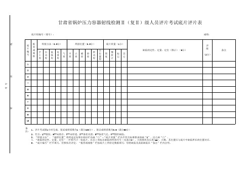
成绩:线
封
密备注: 进考场时间:出考场时间:甘肃省锅炉压力容器射线检测Ⅱ(复Ⅱ)级人员评片考试底片评片表 底片组编号(袋号):1、评片考试限1小时完成,复试成绩系数为1(满分100分),取证成绩系数为0.6(满分60分)
2、代号:L--裂纹、H--未熔合、T--未焊透、Z--条状夹渣、K--条状气孔、Y--圆形缺陷。
考试日期:考
号
5、“底片编号”栏不填写、但要依次评定:“板厚或规格”栏按底片上所给定数据填写:母材缺陷及表面缺陷在“备注”栏内注明。
主考人: 监考人:4、“缺陷的定性、定量、定位”一栏相当于一张底片,在其上须标出缺陷的性质代号(见备注2)、大致图形及长度(mm)、点数,其位置应与底片中缺陷所在的位置对应。
3、“焊接方法”、“施焊位置”将所选定结果在相应栏内画“○”;“底片质量”栏内不符合标准要求的画“X”、反之画“○”。
PZGLI007-品质管理-工作职位中英文对照
Finance Supervisor Accounting Manager/Supervisor Accountant / Accounting Trainee Cashier Finance/Accounting Assistant Financial Analysis Manager/Supervisor Financial Analyst Cost Accounting Manager/Supervisor Cost Accounting Specialist Audit Manager/Supervisor Audit Executive/Assistant Tax Manager/Supervisor Tax Executive Others Banking & Financial Services / Insurance Stock Broker Investment Advisor Securities Analyst Investment Manager Treasury Manager/Supervisor Treasury Specialist President/Vice-President/Branch Manager Assets Valuation/Analyst Risk Management Trading / LC Officer Settlement Officer Foreign Exchange Supervisor Senior Relationship Manager Relationship Supervisor/Executive Loan/Credit Officer Bank Teller Statistician Credit Card/E-banking business Develop Actuary Adjuster Insurance Agent/Financial Planner Insurance Office Staff Others Manufacturing/Engineering Plant/Factory Manager Chief Engineer Project Manager/Supervisor Project Engineer Operations Manager Operations Supervisor Production Manager/Workshop Supervisor Production Planning Executive/Officer
焊缝RT底片的评判规律及典型缺陷图谱
焊缝射线照相底片的评判规律一、探伤人员要评片,四项指标放在先*,底片标记齐又正,铅字压缝为废片。
二、评片开始第一件,先找四条熔合线,小口径管照椭圆,根部都在圈里面。
三、气孔形象最明显,中心浓黑边缘浅,夹渣属于非金属,杂乱无章有棱边。
四、咬边成线亦成点,似断似续常相见,这个缺陷最好定,位置就在熔合线。
五、未焊透是大缺陷,典型图象成直线,间隙太小钝边厚,投影部位靠中间。
六、内凹只在仰焊面,间隙太大是关键,内凹未透要分清,内凹透度成弧线。
七、未熔合它斜又扁,常规透照难发现,它的位置有规律,都在坡口与层间。
八、横裂纵裂都危险,横裂多数在表面,纵裂分布范围广,中间稍宽两端尖。
九、还有一种冷裂纹,热影响区常发现,冷裂具有延迟性,焊完两天再拍片。
十、有了裂纹很危险,斩草除根保安全,裂纹不论长和短,全部都是Ⅳ级片。
十一、未熔和也很危险,黑度有深亦有浅,一旦判定就是它,亦是全部Ⅳ级片。
十二、危害缺陷未焊透,Ⅱ级焊缝不能有,管线根据深和长,容器跟着条渣走**。
十三、夹渣评定莫着忙,分清圆形和条状,长宽相比3为界,大于3倍是条状。
十四、气孔危害并不大,标准对它很宽大,长径折点套厚度,中间厚度插入法。
十五、多种缺陷大会合,分门别类先评级,2类相加减去Ⅰ,3类相加减Ⅱ级。
十六、评片要想快又准,下拜焊工当先生,要问诀窍有哪些,焊接工艺和投影。
注:*四项指标系底片的黑度、灵敏度、清晰度、灰雾度必须符合标准的要求。
**指单面焊的管线焊缝和双面焊的容器焊缝内未焊透的判定标准。
Radiograph Interpretation - WeldsIn addition to producing high quality radiographs, the radiographer must also be skilled in radiographic interpretation. Interpretation of radiographs takes place in three basic steps which are (1) detection, (2) interpretation, and (3) evaluation. All of these steps make use of the radiographer's visual acuity. Visual acuity is the ability to resolve a spatial pattern in an image. The ability of an individual to detect discontinuities in radiography is also affected by the lighting condition in the place of viewing, and the experience level for recognizing various features in the image. The following material was developed to help students develop an understanding of the types of defects found in weldments and how they appear in a radiograph.DiscontinuitiesDiscontinuities are interruptions in the typical structure of a material. These interruptions may occur in the base metal, weld material or "heat affected" zones. Discontinuities, which do not meet the requirements of the codes or specification used to invoke and control an inspection, are referred to as defects.General Welding DiscontinuitiesThe following discontinuities are typical of all types of welding.Cold lap is a condition where the weld filler metal does not properly fuse with the base metal or the previous weld pass material (interpass cold lap). The arc does not melt the base metal sufficiently and causes the slightly molten puddle to flow into base material without bonding.Porosity气孔is the result of gas entrapment in the solidifying metal. Porosity can take many shapes on a radiograph but often appears as dark round or irregular spots or specks appearing singularly, in clusters or rows. Sometimes porosity is elongated and may have the appearance of having a tail This is the result of gas attempting to escape while the metal is still in a liquid state and is called wormhole porosity. All porosity is a void in the material it will have a radiographic density more than the surrounding area..Cluster porosity链状气孔is caused when flux coated electrodes are contaminated with moisture. The moisture turns into gases when heated and becomes trapped in the weld during the welding process. Cluster porosity appear just like regular porosity in the radiograph but the indications will be grouped close together.Slag inclusions夹渣 are nonmetallic solid material entrapped in weld metal or between weld and base metal. In a radiograph, dark, jagged asymmetrical shapes within the weld or along the weld joint areas are indicative of slag inclusions.Incomplete penetration (IP) or lack of penetration (LOP)未焊透occurs when the weld metal fails to penetrate the joint. It is one of the most objectionable weld discontinuities. Lack of penetration allows a natural stress riser from which a crack may propagate. The appearance on a radiograph is a dark area with well-defined, straight edges that follows the land or root face down the center of the weldment.Incomplete fusion未熔合is a condition where the weld filler metal does not properly fuse with the base metal. Appearance on radiograph: usually appears as a dark line or lines oriented in the direction of the weld seam along the weld preparation or joining area.Internal concavity or suck back内凹或吸入is condition where the weld metal has contracted as it cools and has been drawn up into the root of the weld. On a radiograph it looks similar to lack of penetration but the line has irregular edges and it is often quite wide in the center of the weld image.Internal or root undercut内部或根部咬边is an erosion of the base metal next to the root of the weld. In the radiographic image it appears as a dark irregular line offset from the centerline of the weldment. Undercutting is not as straight edged as LOP because it does not follow a ground edge.External or crown undercut外部或顶部咬边is an erosion of the base metal next to the crown of the weld. In the radiograph, it appears as a dark irregular line along the outside edge of the weld area.Offset or mismatch错边are terms associated with a condition where two pieces being welded together are not properly aligned. The radiographic image is a noticeable difference in density between the two pieces. The difference in density is caused by the difference in material thickness. The dark, straight line is caused by failure of the weld metal to fuse with the land area.Inadequate weld reinforcement未填满is an area of a weld where the thickness of weld metal deposited is less than the thickness of the base material. It is very easy to determine by radiograph if the weld has inadequate reinforcement, because the image density in the area of suspected inadequacy will be more (darker) than the image density of the surrounding base material.Excess weld reinforcement增强余高is an area of a weld, which has weld metal added in excess of that specified by engineering drawings and codes. The appearance on a radiograph is a localized, lighter area in the weld. A visual inspection will easily determine if the weld reinforcement is in excess of that specified by the individual code involved in the inspection.Cracking裂纹can be detected in a radiograph only the crack is propagating in a direction that produced a change in thickness that is parallel to the x-ray beam. Cracks will appearas jagged and often very faint irregular lines. Cracks can sometimes appearing as "tails" on inclusions or porosity.Discontinuities in TIG weldsThe following discontinuities are peculiar to the TIG welding process. These discontinuities occur in most metals welded by the process including aluminum and stainless steels. The TIG method of welding produces a clean homogeneous weld which when radiographed is easily interpreted.Tungsten inclusions. 夹钨Tungsten is a brittle and inherently dense material used in the electrode in tungsten inert gas welding. If improper welding procedures are used, tungsten may be entrapped in the weld. Radiographically, tungsten is more dense than aluminum or steel; therefore, it shows as a lighter area with a distinct outline on the radiograph.Oxide inclusions夹氧化物are usually visible on the surface of material being welded (especially aluminum). Oxide inclusions are less dense than the surrounding materials and, therefore, appear as dark irregularly shaped discontinuities in the radiograph.Discontinuities in Gas Metal Arc Welds (GMAW)The following discontinuities are most commonly found in GMAW welds.Whiskers are short lengths of weld electrode wire, visible on the top or bottom surface of the weld or contained within the weld. On a radiograph they appear as light, "wire like" indications.Burn through (icicles) results when too much heat causes excessive weld metal to penetrate the weld zone. Lumps of metal sag through the weld creating a thick globular condition on the back of the weld. On a radiograph, burn through appears as dark spots surrounded by light globular areas.welld-02 (Incomplete Root Fusion、根部未熔合)—welld-03 (Insuffucient Reinforcement、增强高)——welld-04 (Excess Root Penetration、根部焊瘤)——welld-05 (External Undercut、外部咬肉)——welld-06 (Internal Undercut、内部咬肉)——welld-07 (Root Concavity、根部凹陷)——welld-08 (Burn Through、烧穿)——welld-09 (Isolated Slag Inclusion、单个的夹渣)——welld-10 (Wagon Track - Slag Line、线状夹渣)——welld-11 (Interrun Fusion、内部未熔合)——welld-12 (Lack of Sidewall Fusion、内侧未熔合)——welld-13 (Porosity、气孔)——welld-14 (Cluster Porosity、链状气孔)——welld-15 (Hollow Bead、夹珠)——welld-16 (Transverse Crack、横向裂纹)——welld-17 (Centerline Crack、中心线裂纹)——welld-18 (Root Crack、根部裂纹)——welld-19 (Tungsten Inclusion)夹钨—。
焊缝射线探伤底片的评定-tukingcai的日志-网易博客

焊缝射线探伤底片的评定-tukingcai的日志-网易博客二、底片质量的评定1.测黑度值黑度值(黑化程度,含Ag越多,则黑度较大)可用黑度计(光密度计)直接测量规定部位。
D=lg L0:照射光强;L:透过光强。
底片初始灰雾度D0:指未经曝光的胶片经显影处理后获得的微小黑度。
D0<0.2,影响不大;D0>0.2,则降低对比度和灵敏度。
2.测灵敏度灵敏度是以底片上的象质影像反映的象质指数来表示的。
底片上必须有象质计显示,且位置正确,被检测部位必须达到线型象质计的选用灵敏度要求。
线型象质计的选用定位标记、识别标记与B标记等是否正确、齐全。
4.检验表面质量影像规整齐全,不可缺边或缺角,无伪缺陷。
常见伪缺陷及其原因三、底片上缺陷影像的识别1.焊接缺陷在射线探伤中的显示(见书P/153 表7-1)焊接缺陷显示特点2.焊接缺陷的识别(1)几何形状(2)黑度分布(3)位置四、焊接缺陷的定量测定1.埋藏深度的确定5.在射线方向的尺寸(见书P/155)图7-19五、焊缝质量的评定缺陷:圆形缺陷(长宽比≤3)、条状夹渣(长宽比>3)、未焊透、未熔合、裂纹。
焊缝质量分级表1.圆形缺陷的评定步骤:先确定评定区域、量缺陷的长径、换算成点数、再评级。
①选定评定区域圆形缺陷是长宽比≤3的缺陷,它的评定区域见下表。
缺陷评定区域表单位: mm寸换算成缺陷点数。
当缺陷的尺寸小于不计点数的缺陷尺寸表规定时,分级评定时不计该缺陷的点数。
质量等级为Ⅰ级的对接焊接接头和母材公称厚度小于等于5mm的Ⅱ级对接焊接接头,不计点数的缺陷在圆形缺陷评定区域内不得多于10个,超过时对接焊接接头的质量等级应降低一级。
缺陷点数换算表圆形缺陷的分级表(1)出现缺陷长径大于1/2T的圆形缺陷时,评为Ⅳ级;(2)当缺陷与评定区边界相接时,应把它划为评定区内计算点数;(3)对于Ⅰ级焊缝和母材厚度≤5mm的Ⅱ级焊缝,不计点数的圆形缺陷在评定区内不得多于10个;(4)当评定区附近缺陷较少时,且认为只用该评定区大小划分级别不适当时,可将评定区沿焊缝方向扩大到3倍,求出缺陷点数,用此值的1/3进行评定。
焊缝质量检验级别表.doc
《
月
旬生产进度计划表》
工程名称:
加 工程量 序号 工 (根/T) 号 材料 工艺 下料 钻铣 装配 焊接
编制日期:
矫正 清理 成品 检验 喷砂 备注 油漆
合计
编制:
审核:
批准:
生产会议记要
施工质量安全技术交底卡
施工单位: 工程名称 施工项目部位 技术交底内容: 承接施工单位 或班组
承接人:
交底单位:
交底人:
(签名)
年
月
日
(签名)
年
月
日
《重要结构或产品放大样检验记录表》
工程名称
图纸编号
构件型号
大样简图:
尺寸代号 图纸名义尺寸 大样实测尺寸 偏差 A B C D E 检验结论:
尺寸代号 图纸名义尺寸 大样实测尺寸 F G H I J
偏差
放样人/日期: 大样检验评定结论:
检验员/日期:
质保部经理/日期:
4
气孔和 点状夹 渣
在 12δ 的长度内, 在 6δ 的长度内, 不得超过 6L 不得超过 3L
3、点数――是指X射线底片上任何10mm×50mm 焊缝区域内允 许的气孔点数。
气孔点数换算表
气孔直径 <0.5 /mm 换算点数 0.5 0.6~ 1.0 1 1.1~ 1.6~ 1.5 2 2.0 3 2.1~ 3.0 5 3.1~ 4.0 8 4.1~ 5.0 12 5.1~ 6.0 16 6.1~ 7.0 20
X 射线检验质量标准表
顺序 1 2 主要项目 裂 纹 未熔合 质量标准 一级 不允许 不允许 二级 不允许 不允许 不允许 深度≤10%δ ,但 不大于 1.5mm, 长度≤条状夹渣 总长 点数 6 9 12 18 24 2/3δ