FDH700中文资料
分子泵控制器FD

4、使用方法: ......................................................................................................................................16
5、故障代码 ..........................................................................................................................................17
6、常见故障处理 ..................................................................................................................................17
KYKY MODBUS 通信手册 ......................................................................................................................19
2、产品简介 ............................................................................................................................................6
2.1 产品型号及铭牌 ............................................................................................................................6 2.2 产品一览表 ....................................................................................................................................6 2.3 产品外观 ........................................................................................................................................6 2.4 FD 系列控制器与分子泵型号匹配表 ..........................................................................................8 2.5 性能指标 ........................................................................................................................................8
BT系列发光二极管FDBS系列显示器

* 封 装 形 式 D ・ W ・ C ・ T D ・ W ・ C ・ T D ・ W ・ C ・ T D ・ W ・ C ・ T --
图
例
同类 产品 型号
BT302G BT303 Φ8 BT304 BT305 BT306 BT412 BT412G
2×5 有台
橙 绿 黄 双 蓝 红 橙 绿 黄 双 蓝 红 橙 绿 黄 双 蓝 红 绿 黄 蓝 --
700 800 1000 1000 700 800 1000 1000 600
1000
660 660 505 590 660 660 505 590 660 660 505 590 660 660 505 590 --
30 30 30 30 30 30 30 30 30 30 30 30 30 30 30 30 ----T F4 T F3 T F2 T F1
电流型指示灯参数表采用限制工作电流的方法使用主要参数vfifmir灯头尺寸参数型号颜色vmaa外型图例质量等级fdr300红22fdg300绿25fdy300黄253050fdb300兰45201003fdw300白45201003led带反射罩或固定装置m6f7jfdr500红22fdg500绿25fdy500黄253050fdb500兰4520100fdw500白45201005led带反射罩或固定装置m8f8a型jfdr500y红22fdg500y绿255fdy500y黄2530505led带反射罩或固定装置m10f8c型jfdr700s红22fdg700s绿25fdy700s黄2530508fdb700s兰45201008led带反射罩或固定装置m12f9a型fdr700s红22fdg700s绿25fdy700s黄25305010fdb700s兰452010010led带反射罩或固定装置m14f9bfdr700s红22fdg700s绿25fdy700s黄25305012fdb700s兰452010012led带反射罩或固定装置m16f9c测试条件if10mavr5v发光二极管指示灯电压型指示灯参数表可直接采用6v12v24vv28v等额定电压工作主要参数vfifir灯头尺寸参数型号颜色vmaa外型图例质量等级fdr506615fdr51212fdr524245fdr528红2820505led带反射罩或固定装置m8f8b型jfdg506615fdg51212fdg524245fdg528绿2820505led带反射罩或固定装置m8f8b型jfdy506615fdy51212fdy524245fdy528黄2820505led带反射罩或固定装置m8f8b型jfdr706615fdr71212fdr724248fdr728红2820508led带反射罩或固定装置m14f91jfdg706615fdg71212fdg724248fdg728绿2820508led带反射罩或固定装置m14f91jfdy706615fdy71212fdy724248fdy728黄2820508led带反射罩或固定装置m14f91jfdr712p红12fdg712p绿128fdy712p黄1220508led带反射罩或固定装置m14f92j测试条件参考值vrvf特性与用途ledled平面发光显示器是由多个dled芯片组成的平面发光器件
DF8003D使用手册_数据采集
DF8003/DF8003D调度中心自动化系统使用手册3.0数据采集东方电子股份有限公司版权所有©东方电子股份有限公司,保留所有权利。
本手册力求反映系统的最新发展及改进信息,会作及时更新,请注意核实所用产品版本与手册的吻合。
目录第1 章使用指南.................................................................................................................. - 5 -1.1 编写目的.................................................................................................................. - 5 -1.2 有关商务.................................................................................................................. - 5 -1.3 安装提示.................................................................................................................. - 5 -1.4 标志说明.................................................................................................................. - 5 - 第2 章前置基本概念.......................................................................................................... - 6 -2.1 相关术语和缩略语说明.......................................................................................... - 6 -2.2 前置系统基本概念.................................................................................................. - 6 -2.3 配置方案.................................................................................................................. - 7 -2.4 前置模块说明.......................................................................................................... - 8 - 第3 章配置说明.................................................................................................................. - 9 -3.1 前置服务器的配置.................................................................................................. - 9 -3.2 通道参数设置........................................................................................................ - 10 -3.3 RTU接入典型步骤............................................................................................... - 12 -3.4 转发........................................................................................................................ - 13 -3.5 下行切换................................................................................................................ - 14 -3.6 既收又发................................................................................................................ - 14 -3.7 透明报文转发........................................................................................................ - 15 -3.8 GPRS的接入......................................................................................................... - 15 -3.9 前置模拟事故总.................................................................................................... - 15 -3.10 前置计算................................................................................................................ - 15 -3.11 报文和日志保存.................................................................................................... - 16 - 第4 章常用规约设置........................................................................................................ - 17 -4.1 CDT规约............................................................................................................... - 17 -4.2 IEC101规约 .......................................................................................................... - 17 -4.3 IEC104规约 .......................................................................................................... - 17 -4.4 IEC101转发规约 .................................................................................................. - 18 -4.5 IEC104转发规约 .................................................................................................. - 18 - 第5 章参数说明................................................................................................................ - 20 -5.1 前置配置表............................................................................................................ - 20 -5.2 通道参数表............................................................................................................ - 20 -5.3 前置终端服务器表................................................................................................ - 22 -5.4 RTU参数表........................................................................................................... - 22 -5.5 RTU路径参数表................................................................................................... - 23 -5.6 通讯组表................................................................................................................ - 23 -5.7 通讯参数表............................................................................................................ - 24 -5.8 通道透明转发表.................................................................................................... - 24 -5.9 GPRS参数表......................................................................................................... - 24 -5.10 前置事故总配置表................................................................................................ - 24 -5.11 前置计算配置表.................................................................................................... - 25 -5.12 通道报文日志表.................................................................................................... - 25 - 第6 章COMVIEW使用说明 ........................................................................................... - 26 -6.1 COMVIEW主界面 ............................................................................................... - 26 -6.2 RTU参数及状态显示........................................................................................... - 27 -6.3 实时数据显示及其调试........................................................................................ - 28 -6.4 路径参数及状态.................................................................................................... - 29 -6.5 通道参数及状态.................................................................................................... - 30 -6.6 报文显示及通讯调试............................................................................................ - 30 -6.7 其他参数................................................................................................................ - 32 -6.8 其他工具................................................................................................................ - 32 - 第7 章COMC使用说明................................................................................................... - 34 - 第8 章常见问题................................................................................................................ - 35 -8.1 通讯问题................................................................................................................ - 35 -8.2 规约调试................................................................................................................ - 35 -8.3 规约更换................................................................................................................ - 36 -8.4 COMS进程频繁退出 ........................................................................................... - 36 -8.5 TCP端口的复用 ................................................................................................... - 36 -8.6 调度系统转发........................................................................................................ - 36 -8.7 双遥控号对照表的设置........................................................................................ - 36 -8.8 网络通道通讯异常问题查找................................................................................ - 37 - 第9 章附录........................................................................................................................ - 39 -9.1 单组前置容量说明................................................................................................ - 39 -9.2 TXB1B机箱切换报文格式 .................................................................................. - 40 -第 1 章使用指南1.1 编写目的本手册的编写目的主要是对系统的功能进行详细说明,使电网运行人员、工程安装人员在使用系统时能够提供方便、有效地帮助。
H700说明书

使用 H700 ..........................................................................................................................28
开机和关机 .....................................................................................................................29 佩戴耳机 .........................................................................................................................30 两耳交换佩戴 .................................................................................................................31 改变音量按钮方向 .........................................................................................................32 进行通话 .........................................................................................................................33 进行通话 继续 ............................................................................................................34 指示灯 .............................................................................................................................35 声音提示 ........................................................................................................................36 疑难问题解答 ................................................................................................................37
F200说明书

FD270中文资料
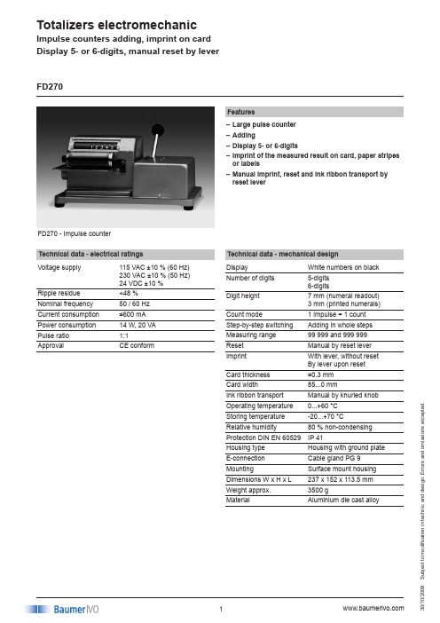
Totalizers electromechanicS u b j e c t t o m o d i fi c a t i o n i n t e c h n i c a n d d e s i g n . E r r o r s a n d o m i s s i o n s e x c e p t e d .008FD270 - Impulse counterFeaturesLarge pulse counter –Adding–Display 5- or 6-digits–Imprint of the measured result on card, paper stripes –or labelsManual imprint, reset and ink ribbon transport by –reset leverTechnical data - electrical ratings Voltage supply115 VAC ±10 % (60 Hz) 230 VAC ±10 % (50 Hz) 24 VDC ±10 %Ripple residue <48 %Nominal frequency 50 / 60 Hz Current consumption ≤600 mA Power consumption 14 W, 20 VA Pulse ratio 1:1ApprovalCE conformFD270Technical data - mechanical design DisplayWhite numbers on black Number of digits 5-digits 6-digitsDigit height7 mm (numeral readout) 3 mm (printed numerals)Count mode1 impulse = 1 count Step-by-step switching Adding in whole steps Measuring range 99 999 and 999 999Reset Manual by reset lever Imprint With lever, without reset By lever upon reset Card thickness ≤0.3 mm Card width 85...0 mmInk ribbon transport Manual by knurled knob Operating temperature 0...+60 °C Storing temperature -20...+70 °CRelative humidity 80 % non-condensing Protection DIN EN 60529IP 41Housing type Housing with ground plate E-connection Cable gland PG 9 MountingSurface mount housing Dimensions W x H x L 237 x 152 x 113.5 mm Weight approx.3500 gMaterialAluminium die cast alloyImpulse counters adding, imprint on card Display 5- or 6-digits, manual reset by leverTotalizers electromechanicS u b j e c t t o m o d i fi c a t i o n i n t e c h n i c a n d d e s i g n . E r r o r s a n d o m i s s i o n s e x c e p t e d .008FD270Part number FD270.DisplayA55-digits 9999.9 A75-digits 99999 C16-digits 999 999B76-digits 99999.5,count mode 0-5-0-5Voltage 124 VDC5115 VAC / 60 Hz 6230 VAC / 50 HzImprint / reset010A Imprint and reset operation parallel020CImprint and reset operation separateImpulse counters adding, imprint on card Display 5- or 6-digits, manual reset by leverConnection diagramDimensionsVoltage 24 VDC ±10 %Power14 W Nominal current 600 mA Resistance 38 ΩVoltage 115 VAC ±10 %Power20 VA Nominal current 180 mA Resistance 50 ΩVoltage 230 VAC +6/-10 %Power20 VA Nominal current 80 mA Resistance290 ΩTrigger level。
FD-103 全自动前照灯检测仪(屏幕法) 使用说明书 V1.0
目录一、仪器结构 (1)1.仪器外形 (1)2.台架结构 (2)3.仪器台架说明: (3)二、设备使用方法 (3)1.地基图与设备 (3)2.操作使用步骤 (5)三、设备维护 (25)1.日常维护 (25)2.日常维护简单故障处理 (26)四、设备参数和主要指标 (27)1.主要技术指标 (27)五、仪器与上位机通信协议 (28)1.仪器发送的命令格式 (28)2.仪器应答的命令格式: (29)3.命令说明: (30)六、附录(装箱清单) (35)一、 仪器结构1. 仪器外形见图一2.台架结构见图二图二1.工控机柜2.显示器3.键盘、鼠标4.图像采集系统5.工控主机6.工控机柜门3.仪器台架说明:FD-103 全自动前照灯检测仪(屏幕法)主要由采光板、工控机柜、工控主机、控制系统、图像采集系统等组成。
(见图一)(1)控制系统组成结构控制系统主要由工控主机、显示器、键盘、鼠标,控制电路电器等部分组成。
(见图二) (2)图像采集系统组成结构图像采集系统主要由摄像设备、图像采集设备等部分组成。
二、 设备使用方法1.地基图与设备(1)布局的准备:前照灯检测仪的布局对检测仪的测试结果有很大的影响,为保证安装后设备正常工作、达到预期的测 试效果,请务必按照布局图安装。
(见图三)图三设备布局平面图(2)设备的安装:设备安装的精度高低,直接影响设备的正常运行和测试精度。
因此,对设备台架的安装,必须严格执行安装标准、安装要求;(3)确定采光屏的摆放位置,标出检测线的中轴线;(4)检测距离:3m;(5)摄像头与采光屏距离:3.2m,与检测线中轴线垂直距离500mm,摄像头高度离地800mm;(6)按(5)的要求摆放好主机柜;(7)在采光屏和主机柜的底板上4个φ10孔下的地板打上标记,移开设备,用冲击钻打4个深度为90mm的孔;(8)在上述的孔中,用安装附件中所带拉爆螺钉M8×80,在保证(5)的要求下,将设备固定在地面上。
PAF700F Series 全 brick DC-DC 转换器说明书
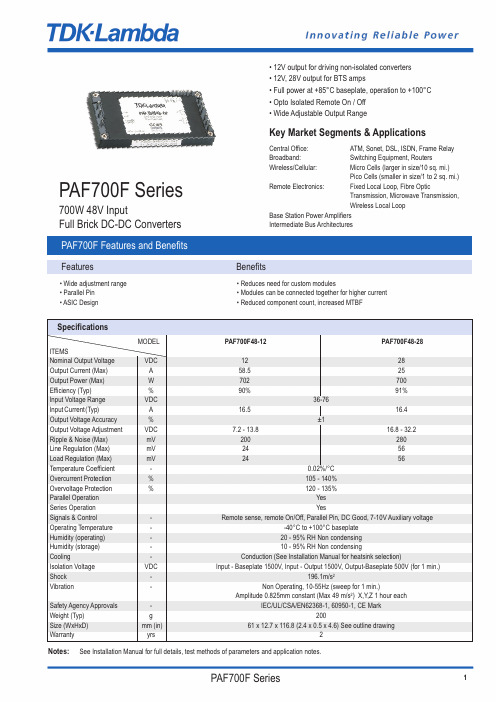
PAF700F Series700W 48V InputFull Brick DC-DC ConvertersKey Market Segments & ApplicationsCentral Office:ATM, Sonet, DSL, ISDN, Frame Relay Broadband:Switching Equipment, RoutersWireless/Cellular:Micro Cells (larger in size/10 sq. mi.)Pico Cells (smaller in size/1 to 2 sq. mi.)Remote Electronics:Fixed Local Loop, Fibre OpticTransmission, Microwave Transmission,Wireless Local LoopBase Station Power Amplifiers Intermediate Bus Architectures • 12V output for driving non-isolated converters • 12V, 28V output for BTS amps• Full power at +85°C baseplate, operation to +100°C • Opto Isolated Remote On / Off • Wide Adjustable Output RangePAF700F Features and BenefitsFeaturesBenefits• Wide adjustment range • Reduces need for custom modules• Parallel Pin • Modules can be connected together for higher current • ASIC Design• Reduced component count, increased MTBFSpecificationsNotes: See Installation Manual for full details, test methods of parameters and application notes.MODEL PAF700F48-12PAF700F48-28ITEMSNominal Output Voltage VDC 1228Output Current (Max)A 58.525Output Power (Max)W 702700Efficiency (Typ)%90% 91%Input Voltage Range VDC 36-76Input Current(Typ)A 16.516.4Output Voltage Accuracy %±1Output Voltage Adjustment VDC 7.2 - 13.816.8 - 32.2Ripple & Noise (Max)mV 200280Line Regulation (Max)mV 2456Load Regulation (Max)mV 2456Temperature Coefficient -0.02%/°C Overcurrent Protection %105 - 140%Overvoltage Protection %120 - 135%Parallel Operation Yes Series Operation YesSignals & Control-Remote sense, remote On/Off, Parallel Pin, DC Good, 7-10V Auxiliary voltageOperating Temperature --40°C to +100°C baseplate Humidity (operating)-20 - 95% RH Non condensing Humidity (storage)-10 - 95% RH Non condensingCooling-Conduction (See Installation Manual for heatsink selection)Isolation Voltage VDC Input - Baseplate 1500V, Input - Output 1500V, Output-Baseplate 500V (for 1 min.)Shock -196.1m/s 2Vibration-Non Operating, 10-55Hz (sweep for 1 min.)Amplitude 0.825mm constant (Max 49 m/s 2) X,Y,Z 1 hour eachSafety Agency Approvals -IEC/UL/CSA/EN62368-1, 60950-1, CE MarkWeight (Typ)g 200Size (WxHxD)mm (in) 61 x 12.7 x 116.8 (2.4 x 0.5 x 4.6) See outline drawingWarrantyyrs2Note1Use external fuse of fast blow type, for each unit2Put input capacitor, C1 and C2, greater than 220uf for each. If the impedance of input line is high, C1 and C2 capacitance must be greater than above.3Put output capacitor, C3 (12v: more than 470uF,28V: greater than 220uF). If the ambient temperature is less than -20C, use 4 pieces of therecommended capacitor above.4Refer to instruction manual for further details.Full Brick Max Power Full Nominal Input Output Option SuffixWatts Function VoltageVoltage PAF700F4812 or 28Blank = M3 Tapped insertsT = 3.3mm Non-threaded through holeConnection ExampleDerating CurvePart Number SchemeOutline Drawing PAF700FNoteA:Model name, input voltage range, nominal output voltage, maximum output current,country of manufacture are shown here in accordance with the specificationsB:M3 tapped holes for customer chassis mounting (FG)C:Input and output pin: 8-02D:Signal pin : 8-01E:Unless otherwise specified dimensional tolerance +0.3mmPinoutPin Description Function-Vin Negative Input Terminal+Vin Positive Input Terminal- ON/OFF Remote On/Off Negative Terminal+ON/OFF Remote On/Off Positive Terminal+V Positive Output Terminal-V Negative Output TerminalAUX7-10V Aux VoltageIOG DC GoodPC Parallel Control ConnectionTRIM Output Adjustment Trim Pin+S Positive Remote Sense-S Negative Remote SensePAF700F Oct20 v3TDK-Lambda France SAS3 Avenue du CanadaParc TechnopolisBâtiment Sigma91940 les UlisFranceTel:+33 1 60 12 71 65Fax:+33 1 60 12 71 66********************.com/frItaly Sales OfficeVia Giacomo Matteotti 6220092 Cinisello Balsamo (MI)ItalyTel:+39 02 61 29 38 63Fax:+39 02 61 29 09 00*************************.com/itNetherlands******************.com/nlTDK-Lambda Germany GmbHKarl-Bold-Strasse 4077855 AchernGermanyTel:+49 7841 666 0Fax:+49 7841 5000**************************.com/deAustria Sales OfficeAredstrasse 222544 LeobersdorfAustriaTel:+43 2256 655 84Fax:+43 2256 645 12******************.com/atSwitzerland Sales OfficeEichtalstrasse 558634 HombrechtikonSwitzerlandTel:+41 44 850 53 53Fax:+41 44 850 53 50******************.com/chNordic Sales OfficeHaderslevvej 36BDK-6000 KoldingDenmarkTel:+45 8853 8086******************.com/dkTDK-Lambda UK Ltd.Kingsley AvenueIlfracombeDevon EX34 8ESUnited KingdomTel:+44 (0) 12 71 85 66 66Fax:+44 (0) 12 71 86 48 94******************.com/ukTDK-Lambda Ltd.1 Alexander YanaiSegulaPetah-TikvaIsraelTel:+9 723 902 4333Fax:+9 723 902 4777******************.il/ilC.I.S.Commercial Support:Tel:+7 (495) 665 2627Technical Support:Tel:+7 (812) 658 0463******************/ruLocal Distribution。
百兆紧凑型工业光电转换器光纤收发器使用说明书
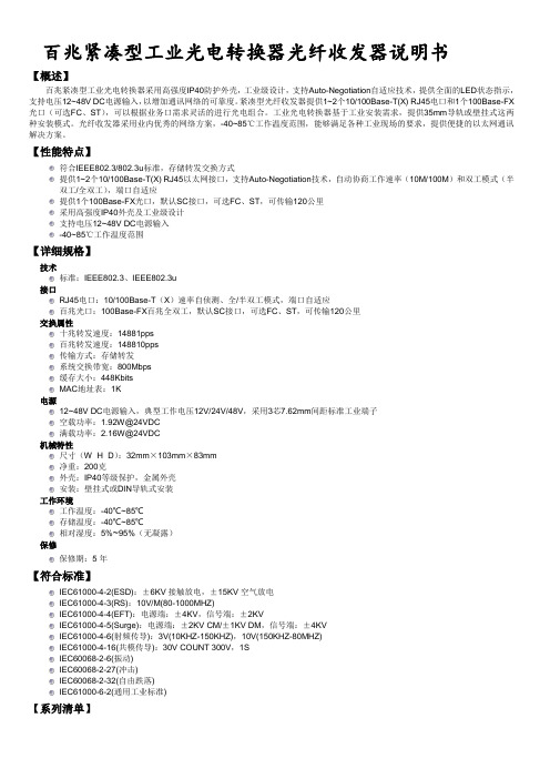
百兆紧凑型工业光电转换器光纤收发器说明书【概述】百兆紧凑型工业光电转换器采用高强度IP40防护外壳,工业级设计,支持Auto-Negotiation自适应技术,提供全面的LED状态指示,支持电压12~48V DC电源输入,以增加通讯网络的可靠度。
紧凑型光纤收发器提供1~2个10/100Base-T(X) RJ45电口和1个100Base-FX 光口(可选FC、ST),可以根据业务口需求灵活的进行光电组合。
工业光电转换器基于工业安装需求,提供35mm导轨或壁挂式这两种安装模式。
光纤收发器采用业内优秀的网络方案,-40~85℃工作温度范围,能够满足各种工业现场的要求,提供便捷的以太网通讯解决方案。
【性能特点】符合IEEE802.3/802.3u标准,存储转发交换方式提供1~2个10/100Base-T(X) RJ45以太网接口,支持Auto-Negotiation技术,自动协商工作速率(10M/100M)和双工模式(半双工/全双工),端口自适应提供1个100Base-FX光口,默认SC接口,可选FC、ST,可传输120公里采用高强度IP40外壳及工业级设计支持电压12~48V DC电源输入-40~85℃工作温度范围【详细规格】技术标准:IEEE802.3、IEEE802.3u接口RJ45电口:10/100Base-T(X)速率自侦测、全/半双工模式,端口自适应百兆光口:100Base-FX百兆全双工,默认SC接口,可选FC、ST,可传输120公里交换属性十兆转发速度:14881pps百兆转发速度:148810pps传输方式:存储转发系统交换带宽:800Mbps缓存大小:448KbitsMAC地址表:1K电源12~48V DC电源输入,典型工作电压12V/24V/48V,采用3芯7.62mm间距标准工业端子空载功率:1.92W@24VDC满载功率:2.16W@24VDC机械特性尺寸(W×H×D):32mm×103mm×83mm净重:200克外壳:IP40等级保护,金属外壳安装:壁挂式或DIN导轨式安装工作环境工作温度:-40℃~85℃存储温度:-40℃~85℃相对湿度:5%~95%(无凝露)保修保修期:5年【符合标准】IEC61000-4-2(ESD):±6KV接触放电,±15KV空气放电IEC61000-4-3(RS):10V/M(80-1000MHZ)IEC61000-4-4(EFT):电源端:±4KV,信号端:±2KVIEC61000-4-5(Surge):电源端:±2KV CM/±1KV DM,信号端:±4KVIEC61000-4-6(射频传导):3V(10KHZ-150KHZ),10V(150KHZ-80MHZ)IEC61000-4-16(共模传导):30V COUNT 300V,1SIEC60068-2-6(振动)IEC60068-2-27(冲击)IEC60068-2-32(自由跌落)IEC61000-6-2(通用工业标准)【系列清单】【产品外观】Ck1011 Ck1021 【LED 指示灯】【接地和电源连接】设备接地:转换器上侧板出有一接地螺丝,此点连接接地线的一端,另一端需可靠接入机房的大地。
伊林思H700 系列3G 4G 双卡千兆路由器规格说明书

H700系列3G/4G双卡千兆路由器规格说明书产品概述H700系列路由器是伊林思科技有限公司基于无线网络需求,采用最新硬件系统平台,使用Linux软件系统引用最新技术研发出来的一款全新的,性能更为优异的物联网无线通信路由器产品。
采用工业级设计标准,它主要应用于行业用户的数据传输业务。
H700支持双SIM卡,双频WiFi,千兆网口及多种工作模式适合不同场景应用。
该产品采用高性能的32位嵌入式处理器,内嵌完备的TCP/IP协议栈,同时提供RS串口和10/100/1000M以太网接口。
集成IO端子座,提供串口或者GPIO接口。
串口分别提供RS-232、RS-485、TTL电平接口的透明传输模式,支持的VPN通信功能,采用IPSec/PPTP/L2TP/GRE/OpenVPN等VPN技术,企业级VPN隧道技术和防火墙技术,保证高安全性行业的数据安全,支持自动在线检测,实时动态刷新网络状态,保持链路畅通,产品以性能稳定、体积小、易于安装嵌入、抵抗环境能力强等优点,深受用户欢迎。
支持WEB/Telnet/Console/TR069/NMS管理系统等多种配置方式,其中用户面对的是WEB图形化管理配制界面,管理方便简单。
该产品已广泛应用于物联网产业链中的M2M/IoT行业,如物流快递柜、充电桩、金融、邮政、智能电网、智能交通、智能家居、智能建筑、环保监测、消防监控、安防监控、水利监测、公共安全、广告发布、供应链自动化、工业自动化、工业控制、地震监测、气象监测、数字化医疗、遥感勘测、仪表监测、农业、林业、水务、煤矿、石化等领域。
行业应用公共服务:物流快递柜、充电桩金融:银行储蓄点机房监控,移动性证券交易和信息查询,ATM机通信:电信机房动力环境监控,通信维护人员线路资料查询交通:GPRS/SMS/GPS 机动车辆监控调度系统;银行运钞车,邮政运输车监控调度公安:公安、110、交警车辆监控调度,公安移动性数据(身份证、犯罪档案等)查询,交警移动通信数据(车辆、司机档案等)查询热力:热力系统实时监控和维护电力:电力系统城市中电网实时监控和自动补偿,远程自动抄表;铁塔监控等;公司:移动办公及管理,其他外勤人员移动性数据查询工业:工业遥感,遥测,遥控信息回报气象:气象数据采集与传输水利:水文监测生活:煤气调压站实时数据采集自动控制,自来水;快递柜;污水管道,闸门、泵站与水厂实时监控维护电子商务:支持B2B、B2C的电子商务和电子支付、股票交易等监控: 视频监控, CCTV>>| 主要功能特性项目内容支持多种网络灵活选择全网通支持中国联通、中国电信、中国移动、中国广电等2G/3G/4G网络工业级应用设计采用高性能工业级无线模块;采用高性能工业级32位双核通讯处理器;支持低功耗模式,包括休眠模式、定时上下线、模式和定时开关机模式;采用金属外壳,保护等级IP30。
Hitachi荧光分光光度计F-7000说明书

Diffraction grating
■ Stigmatic concave diffraction grating, mechanically ruled, resulting in a very bright monochromator of F-number 2.2.
Ruling engine. A dividing engine for ruling diffraction gratings, invented in 1880s by Henry Augustus Rowland of Johns Hopkins University. Compared to a holographic grating, mechanically ruled gratings have the following advantages: (1) Mirror-finished groove surface results in high diffraction efficiency. (2) Groove spacing required for aberration correction can be adjusted,
● High-resolution multi-stage slit with a resolution as small as 1nm
● Shutter control for minimizing sample deterioration
4
Fluorescent intensity Ca2+ (nM)
The acquisition of these data was made possible by the 3-D measurement function and high-speed scanning capability of the F-7000.
FD470中文资料

FICHE TECHNIQUEFD400 RELAIS HERMETIQUE 2 RT DOUBLE COUPURE10 A/56 VccNOTES D'APPLICATION:001007SOCLE ASSOCIE:SFD400CE40ERelais hermétique monostable polariséCombinaison des contacts 2 R(DC) + 2 T(DE)Alimentation bobine Courant continuCARACTERISTIQUES TECHNIQUES PRINCIPALESPrévu pour commuter10 A / 56 VccMasse80 g maxDimensions max. du boîtier enmm26 x 25,7 x 26Armature à forces équilibréesBoîtier métallique hermétique protégé anti-corrosionNon chevauchement des contactsCARACTERISTIQUES ELECTRIQUES DES CONTACTSDurée de vie minimale Tension aux bornes du contact56 Vcc100 000 cycles20 000 cyclesPouvoir de commutation en Ampèressur charge résistivesur charge inductive (L/R=5ms)10650 cycles surcharge résistive40400 000 cycles sous 25% de la charge nominale résistiveLEACH®INTERNATIONALSolutions for Power Switching and ControlNorth America6900 Orangethorpe Ave.P.O. Box 5032Buena Park, CA 90622 USATel: (01) 714-736-7599Fax: (01) 714-670-1145Europe, SA2 Rue Goethe57430 SarralbeFranceTel: (33) 3 87 97 98 97Fax: (33) 3 87 97 84 04Asia-Pacific Ltd.20/F Shing Hing Commercial Bldg.21-27 Wing Kut StreetCentral, Hong KongTel: (852) 2 191 2886Fax: (852) 2 389 5803CARACTERISTIQUES DES BOBINES (Vcc)FD400 CODE A B C E N V Tension nominale (Un)281264828110 Tension maximale291475029125 Tension maximale d'enclenchement à +125° C19,810534,119,875 Tension de déclenchement assuré à -65° C1,50,50,221,55Résistance de la bobine en Ω ±10% à +25° C29070189552905000 Circuit suppresseur (Vcc)N/A N/A N/A N/A-42N/ACARACTERISTIQUES GENERALESGamme de température-65°C à +125°CRigidité diélectrique au niveau de la mer- Entre contacts et masse et entre contacts1250 Veff / 50 Hz- Entre bobine et masse1000 Veff / 50 Hz Rigidité diélectrique à 25 000 m (tous points)350 Veff / 50 HzRésistance d'isolement initiale sous 500 Vcc100 M Ω min Vibrations sinusoïdales (Sauf fixation G, O et R)30 G / 75 à 3000 Hz Vibrations sinusoïdales (uniquement fixation G, O et R)20 G / 75 à 3000 Hz Chocs (sauf fixation G, O et R)200 G / 6 msChocs (uniquement fixation G, O et R)100 G / 6 msDurée maximum d'ouverture des contacts sous l'influence des vibrations et chocs10 µsTemps d'enclenchement sous tension nominale15 ms maxTemps de déclenchement15 ms maxTemps de rebonds 1 ms maxChute de tension dans le contact sous courant nominal- Valeur initiale200 mV maxTYPES DE FIXATIONS FD400Dimensions en mmTolérances générales: ±0,25mmLa fixation k peut être utilisée avec les types de sorties 1 ou 8; elle inlut la fourniture de la cale isolante 10124TYPES DE SORTIESSCHEMA FD400SYSTEME DE REFERENCESFD400 J 2 NRéférence de base_________________________________| | | |1-Fixation (A,B,C,D,G,J,K,O,R)__________________________| | |2-Type de sortie (1,2,4,8)__________________________________| |3-Code bobine (A,B,C,E,N,V)_____________________________________|REMARQUES1. Les relais avec fixations B, D et la sortie 4 sont compatibles avec les socles des familles S400, SF400 et SFD 400.2. Possibilité de cales isolantes.3. Autres fixations ou sorties: nous consulter.CARACTERISTIQUES TYPIQUES DONNEES A TITRE INDICATIFq Variation de la résistance bobine en température: Voir note d'application n° 001q Constante de temps L/R des bobines: 11 msNote d'application N°001CORRECTION LIEE A LA VARIATION DE LA RESISTANCEDU CUIVRE EN FONCTION DE LA TEMPERATUREExemple: Le catalogue donne une résistance à 25°C de 935 ohms. Quelle valeur à 125°C?Le coefficient correcteur sur I'abaque est de 1,39 à 125°C. R devient: 935x1.39=1299 OhmsLa correction s'applique à la résistance bobine ainsi qu'aux tensions de fonctionnementNote d'application N°007DISPOSITIFS D'ECRETAGE POUR RELAISLes bobines de relais sont inductives, c'est ce qui leur permet de créer les efforts et les mouvements qui font fonctionner les contacts. Lorsque la tension est appliquée sur une bobine, le courant qui s'établit génère le flux magnétique créateur del'effort. A la coupure du circuit, la variation de flux inverse génère une tension qui tend à maintenir le courant qui circulait dans la bobine. La tension générée dépend essentiellement du dispositif de coupure. Plus cette coupure est rapide plus la surtension est élevée. Tous les dispositifs de limitation sont basés sur un ralentissement de la vitesse de décroissance du courant.Cette réduction peut présenter l'inconvénient de ralentir également le mouvement interne du relais, donc les conditionsd'ouverture des contacts, avec de ce fait, répercussion sur la durée de vie et la fiabilité.Il est donc important lors de la définition des dispositifs de commande des bobines de bien comprendre ces phénomènes. Caractéristiques typiques des bobinesSur le diagramme ci-contre, la courbe supérieure indique l'état des contacts. (état haut travail, état bas repos, étatintermédiaire en transfert). La courbe inférieure montre la tension qui apparait au bornes de la bobine lorsque le courant est coupé par un contact de relais.La surtension est écrêtée à -300V par la décharge luminescente qui se produit aux bornes de ces contacts. L'écrêtage a une durée de 200 µs après laquelle les variations de courant ne génèrent plus une tension suffisante. La tension décroît jusqu'au début du mouvement de l'équipage mobile, à ce moment la tension remonte du fait de la libération d'énergie des ressorts de contact travail. La tension chute pendant le transfert, puis croît de nouveau, lorsque le circuit magnétique se referme surl'aimant permanent.Les temps d'ouverture se décomposent en:- Temps jusqu'au début de mouvement: 1,5ms- Temps total de mouvement: 2,3ms- Temps de transfert: 1,4msLes différents types d'écrêteurDispositifs passifsLe circuit résistance - capacitéIl élimine le problème de la dissipation, ainsi que les fronts rapides de tension. Avec une bonne adaptation entre capacité et self, il ne ralentit pas l'ouverture. Dans certain cas de relais polarisés l'ouverture peut même être accélérée. La valeur de la capacité peut être calculée en utilisant la formule approximative:C =0,02 x T avec T = temps de réponse à l'enclenchement en ms R = résistance bobine en KOhmsR C = capacité en µFaradLa résistance série doit être comprise entre 0,5 et 1 fois la résistance bobine. Dans le cas de bobine de faible résistance, il faut faire attention au courant de charge de la capacité.Dans l'exemple ci-contre, effectué avec le même relais que précédemment, les temps deviennent:- Temps jusqu'au début du mouvement: 2,2 ms- Temps de transfert: 1,2 msIl y a donc eu une légère accélération de la vitesse de transfert.L'inconvénient principal réside dans le volume de la capacité. Notre exemple utilise un relais à bobine 290 Ohms et temps de réponse 8 ms. On trouve C=0,5 µF. Cette capacité non polarisée de 63 V au minimum, a un volume d'environ 3cm3.L'enroulement bifiliaireLe principe est de disposer, sur le circuit magnétique de la bobine principale, un second enroulement mis en court-circuit. Par une bonne adaptation de la résistance secondaire il est possible de trouver un compromis acceptable entre la surtension et le ralentissement. Cette méthode purement interne au relais présente des difficultés technologiques de réalisation. Pour être efficace aux variations rapides, le couplage entre les deux enroulements doit être parfait. Ceci implique pratiquement des enroulements imbriqués. Le volume occupé par le second enroulement diminue l'efficacité, et donc augmente la puissance nécessaire. Cette méthode ne peut être appliquée efficacement qu'à des produits étudiés spécifiquement pour cette caractéristique.La résistance (en parallèle sur la bobine)Pour présenter une certaine efficacité, la résistance doit être du même ordre de grandeur que la résistance de la bobine. Une résistance de 1,5 fois la bobine va limiter à 1,5 fois la tension d'alimentation. Le temps et la vitesse de retombé sont affectés modérement. L'inconvénient majeur est la puissance dissipée.Les dispositifs à semi-conducteursLa diodeC'est la méthode la plus simple et qui supprime toute surtension. Elle présente toutefois un inconvénient majeur qui est le ralentissement maximum de la vitesse d'ouverture. En effet la diode recycle la totalité de l'énergie dans la bobine elle-même. Le relevé ci-contre est toujours pris sur le même relais. Les temps indiqués par la courbe 2 deviennent:Temps jusqu'au début du mouvement: 14msTemps de transfert: 5msCes temps sont donc multipliés par un coefficient de 4 à 8.La courbe 1 montre le courant dans la bobine. La remonté indique la libération d'énergie des contacts travail. Au moment òu ils s'ouvrent, le courant redevient constant indiquant une ouverture des contacts à vitesse pratiquement nulle.Il résulte de ces caractéristiques que ce type d'écrêtage est absolument à proscrire pour les relais de puissance avec aimant de polarisation. Pour les petits relais ayant à commuter des courants faibles inférieurs à 0,2 A, la dégradation de durée de sa vie n'est pas significative, et la méthode est acceptable.Le réseau diode + résistanceIl permet d'éliminer l'inconvénient résistance seule cité précédemment, et de limiter l'inconvénient diode seule. Il est maintenant préférable d'utiliser le réseau diode + zener.Le réseau diode + zenerComme la résistance, la zener accélère la vitesse de décroissance du courant. En plus elle introduit un seuil de conduction qui permet d'éviter le recyclage de la libération d'énergie lors du mouvement de l'élément mobile.L'enregistrement ci-contre met en évidence ces caractéristiques. La courbe 1 monte la tension qui est écrêtée à -42 V. Les 2 remontées de tension lors de l'ouverture sont inférieures au seuil de conduction.Les temps d'ouverture se décomposent en:- Temps jusqu'au début du mouvement: 2,6ms- Temps total de mouvement: 2,4ms- Temps de transfert: 1,4msLa vitesse d'ouverture des contacts est donc inchangée.FICHE TECHNIQUE SFD400CE40ESOCLE POUR FD400/FD470 RELAISFAMILLE DE SOCLES POUR:Relais FD400 et FD470Socle pour montage sur circuit impriméCARACTERISTIQUES GENERALESTempérature d'utilisation-55°C à +125°CTempérature de stockage-70°C à +150°CResistance d'isolement> 1000 MΩRigidité diélectrique- Entre broches et fixations1500 Vrms / 50 Hz- Entre broches1500 Vrms / 50 HzVibrations sinusoïdales 20 g / 10 à 2000 HzChocs50 g / 11 msFixations livrées 6 vis M3-5. 6 rondelles onduflexLEACH®INTERNATIONAL Solutions for Power Switching and Control North America6900 Orangethorpe Ave.P.O. Box 5032Buena Park, CA 90622 USAEurope, SA2 Rue Goethe57430 SarralbeFranceAsia-Pacific Ltd.20/F Shing Hing Commercial Bldg.21-27 Wing Kut StreetCentral, Hong Kong。
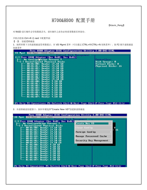
H700&H800 配置手册
2、将光标移至 3 号硬盘,按 F2,在弹出的菜单中,选择 Make Global HS,配置全局的热备盘
3、确认后,3 号硬盘的状态变为 Hotspare
4、移除热备,进入 PD Mgmt 菜单,将光标移至热备盘处,按 F2,选择 Remove Hot Spare,回车移除
配置独立热备: 1、在配置好的虚拟磁盘管理界面下,将光标移至需要配置独立热备的磁盘组上,按 F2 键,在出现的菜单中选 择 Manage Ded. HS
8、可以看到刚才配置成功的虚拟磁盘信息,查看完成后按 esc 键可以返回主界面
9、在此界面,将光标移至图中 Virtual Disk 0 处,按 F2 键可以展开对此虚拟磁盘操作的菜单。 注:左边有+标志的,将光标移至此处,按向右方向键,可以展开子菜单,按向左方向键,可以关闭子菜单
10、如下图红框所示,可以对刚才配置成功的虚拟磁盘(Virtual Disk 0)进行初始化(Initialization),一致性校验 (Consistency Check),删除,查看属性等操作。
11、如果我们要对此虚拟磁盘进行初始化,可以将光标移至 Initialization 处,回车后选择 Start Init。此时会弹出提示窗口, 初始化将会清除所有数据,如果确认要进行初始化操作,在 OK 处按回车即可继续。 注:初始化会清除硬盘、阵列中的所有信息,并且无法恢复
12、确认后会弹出对话框提示初始化完成
2、在虚拟磁盘创建窗口,按回车键选择”Create New VD”创建新虚拟磁盘
3、在 RAID Level 选项按回车,可以出现能够支持的 RAID 级别,根据具体配置的硬盘数量不同,这个位置可能出现的选项也 会有所区别。 选择不同的级别,选项会有所差别。选择好需要配置的 RAID 级别(我们这里以 RAID5 为例),按回车确认。
f-7000 荧光光谱仪仪器参数

一、荧光光谱仪的原理和应用荧光光谱仪是一种用于测量物质荧光发射光谱的仪器。
它利用物质受到紫外或可见光激发后发出的荧光来进行分析和检测。
荧光光谱仪广泛应用于生物医药、环境监测、食品安全等领域,具有灵敏度高、分辨率好、快速准确等特点。
二、荧光光谱仪的参数和规格1. 光源:荧光光谱仪一般采用氙灯或汞灯作为激发光源,氙灯的波长范围广,能够提供较强的激发光,而汞灯则具有比较稳定的输出功率。
2. 分光器:荧光光谱仪的分光器通常采用全息光栅或单色器,能够对荧光光谱进行高效分光和检测。
全息光栅具有分辨率高、光谱范围宽的优点,而单色器则能够提供较高的光谱分辨率。
3. 探测器:荧光光谱仪的探测器一般采用光电二极管(PMT)或光电倍增管(PMT)进行荧光信号的检测和转换。
PMT具有灵敏度高、响应速度快的特点,但对环境要求较高;而PMT则可适用于较恶劣的环境条件下。
4. 光谱范围:荧光光谱仪的光谱范围通常覆盖200-800nm,不同型号的荧光光谱仪具有不同的光谱范围和分辨率。
5. 数据处理系统:现代荧光光谱仪通常配备有先进的数据处理系统,能够实现数据采集、分析和报告输出等功能,提高了检测的自动化程度和准确性。
6. 标定和验证:荧光光谱仪的参数需要经过定期的标定和验证,以确保其检测结果的准确性和可靠性。
三、荧光光谱仪的操作和维护1. 操作:使用荧光光谱仪时,应严格按照操作手册的要求进行操作,保证仪器正常工作。
在操作过程中,应注意仪器的稳定性和光路的清洁,避免外界光线的干扰。
2. 维护:定期对荧光光谱仪进行维护保养,清洁光路和探测器,定期更换光源等关键部件,保证仪器的稳定性和准确性。
四、荧光光谱仪的应用荧光光谱仪在生物医药领域广泛应用于蛋白质、核酸、细胞等生物分子的检测和定量分析;在环境监测领域可以用于水质和大气等环境样品的有机物和金属离子的检测;在食品安全领域可用于食品中有毒物质和添加剂的分析等。
五、总结荧光光谱仪作为一种先进的分析仪器,具有灵敏度高、分辨率好、快速准确等特点,广泛应用于生物医药、环境监测、食品安全等领域。
富士通文件扫描器fi-7700产品说明书

FUJITSU Document Scannerfi-7700With production-class automatic feeding and a large flatbed, the fi-7700 is the best of both worlds. Enable your back office to be more productive and make fewer errors with innovative features for clear, accurate scans - every time.100Pages per minute DuplexScans bothsidesSizes up toDoubleLetter12” x 18” max.ScansPlastic CardsFlat andembossed600Optical DPI24-bit ColorAcceptsSticky NotesTapedReceiptsLabelsTWAIN& ISIS®Supportedfi -7700 Technical Specifi cationsDocument feeding method Automatic Document Feeder (ADF) + FlatbedScanning modes Simplex/Duplex in Color, Grayscale, or Mono-chromeImage sensor type Color Charge-Coupled Device (CCD) x 3(Front x 1, Back x 1, Flatbed x 1)Light source White LED Array x 6 (Front x 2, Back x 2,Flatbed x 2)Multi-feed protection Ultrasonic multi-feed detection sensorPaper detection sensorPaper protection Warped document detectioniSOP (Intelligent Sonic Paper Protection)Document size ADFMinimum 2.0” x 2.7” (50.8 x 69 mm)Maxi-mum12” x 17” (304.8 x 431.8 mm)Long page scan-ning 112” x 220” (304.8 x 5,588 mm)Up to 200m when using auto page truncation Flatbed maximum12” x 18” (304.8 x 457.2 mm)Paper weight Paper 5.3 to 110 lb (20 to 413 g/m2) Plastic card Up to 1.4mm thick 2Scanning speed 3200 or 300 dpi, A4,Color 4, Grayscale 4and Monochrome 5ADFSimplex100 pages/minuteDuplex200 images/minuteFlatbed0.6 secondsADF capacity 6300 Sheets (A4/Letter: 20 lb. or 80 g/m2)Background colors ADF White / Black (switchable) Flatbed White (Black pad optional)Output resolution 7Color (24-bit),Grayscale (8-bit),Monochrome (1-bit)50 to 600 dpi, 600 dpi optical, 1200 dpisoftware 8Internal video processing12-bit (4,096 levels) Interface USB 3.1 Gen 1 / USB 3.0 / USB 2.0 / USB 1.1 Power requirements100 to 240 VAC, 50/60 HzPower consumptionOperating: 64 W or lessSleep mode: 1.7 W or lessAuto-standby (Off) mode: 0.35 W or lessOperating environ-ment Temperature41° F to 95° F (5° C to 35° C) Relative humidity20% to 80% (non-condensing)Dimensions (WxDxH) 927.8” x 19.7” x 13.6”(706 x 500 x 345 mm)Weight77.2 lb (35 kg)Included in the box Stacker, ADF paper chute, AC cable & adapter,USB cable, Setup DVD-ROMBundled software (DVD format)PaperStream IP (TWAIN/ISIS) Driver, 2D Bar-code for PaperStream 10, PaperStream Capture, ScanSnap Manager for fi Series 10, Scan toMicrosoftSharePoint 10, ABBYY FineReader for ScanSnap 10, Scanner Central Admin Agent, SoftwareOperation Panel, Error Recovery GuideEnviromental designations 11ENERGY STAR® and RoHSSupported operating systemsWindows® 10 (32-bit/64-bit),Windows® 8.1 (32-bit/64-bit),Windows® 7 (32-bit/64-bit),Windows Server® 2016 (64-bit), Windows Server® 2012 R2 (64-bit),Windows Server® 2012 (64-bit), Windows Server® 2008 R2 (64-bit), Windows Server® 2008 (32-bit/64-bit)Image processing functionsMulti-image output, Auto color detection, Blank page detection, Dynamic threshold (iDTC), Advanced DTC, SDTC, Error diffusion, De-screen, Emphasis, Halftone, Dropout color, sRGB output, Hole punch removal, Index tab cropping, Split image, De-skew, Edge correc-tion, Streak reduction, Cropping, Dither, Static threshold, Divide long page1 Can scan documents longer than A4 sheets. Documents longer than 34” require using lower resolution (200 DPI or less)2 Can scan up to3 fl at plastic cards or one embossed card at a time 3 Actual scanning speeds are affected by data transmission and software processing times4 Using JPEG compression5 Using TIFF CCITT Group 4 compression6 Maximum capacity varies depending upon paper thickness7 Selectable maximum density may vary depending on length of document8 When scanning at high resolutions (600 dpi or higher), some limitations to document size may apply depending on system environment9 Includes ADF chute and stacker open to minimum positions 10 Can be downloaded following instructions on Setup DVD-ROM 11 PFU Limited, a Fujitsu company, has determined that this product meets the ENERGY STAR® guidelines for energy effi ciency and RoHSrequirements (2005/95/EC)Fujitsu Canada, Inc.155 University Avenue, Suite 1600Toronto, ON M5H 3B7www.fujitsu.ca|**********************.comfi -7700Production-class ADF+Flatbed document scannerIncredible speed and fl exibility■Accurately powers through your documents at up to 200 images per minute■High-capacity 300-page Automatic Document Feeder suitable for continuous scanning■Integrated fl atbed scanner for scanning bound and bulky materials■Accepts a wide variety of documents: thin paper, plastic cards, long documents,and envelopesProtect your paper – and the information on it■Straight paper path reduces the stress on your stack of documents during scanning■Forgot to remove a staple? Intelligent Sonic Paper Protection “listens” to paper fl owingthrough the machine and stops if a misfeed occurs, reducing damage to your documents■Intelligent MultiFeed Function allows easy manual bypass for sticky notes, taped receipts,and labels that can slow down batch scanning■Ultrasonic Double Feed Detection identifi es sheets stuck together so you don’t missan image■Skew Reduction signifi cantly improves feeding performance and ensures that your wholedocument gets accurately captured from edge to edgeClean up and optimize scans without changing settings in advancePaperStream IP (PSIP) is a TWAIN/ISIS ®-compliant driver with smart features including:■Assisted Scanning lets you choose the best image cleanup through visual selection■Advanced Image Cleanup corrects the toughest documents, including colored anddecorated backgrounds, to improve OCR and reduce rescans■Auto Color Detection identifi es the best color mode for the document■Blank Page Detection removes blank pages automatically■Front and Back Merge places two sides of a page into one convenient imagePaperStream Capture makes scanning fast and easyEliminate the learning curve. PaperStream Capture’s user-friendly interface allows easyoperation from start to fi nish. Changing scan settings is simple. Indexing and sortingfeatures include barcode, patch code, and blank page separation – making batch scanninga breeze for operators.Make it even better with PaperStream Capture ProOptional PaperStream Capture Pro software offers an improved feature set with superiorfront-end capture, image processing, and options for enhanced data extraction andindexing for release.Centralized fl eet managementIncludes Scanner Central Admin Agent to remotely manage your entire fi Series fl eet.Effectively allocate your resources based on scan volume, consumables wear, and more.Item Part number DescriptionBlack document pad PA03338-D960Black fl atbed background pad, user-changeableBrake roller PA03740-K010Lifetime: approx 250,000 sheets or 1 yearPick roller PA03740-K011Lifetime: approx 250,000 sheets or 1 year©2017 Fujitsu Computer Products of America, Inc. All rights reserved. Microsoft, SharePoint, and Windows aretrademarks of Microsoft Corporation. ISIS is a registered trademark of EMC Corporation. ABBYY, FineReader aretrademarks of ABBYY Software Ltd. ENERGY STAR is a U.S. registered trademark. PaperStream is registered trademark ofPFU Limited. All other trademarks are the property of their respective owners. Specifi cations subject to change withoutnotice. Printed in USA on paper from responsible sources. Please recycle. 17.0731.1101♼。
维瓦特 VIV-DF-7000 DSLR TTL 用户手册说明书
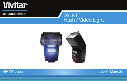
VIV-DF-7000Vivitar One year WarrantyThis warranty covers the original consumer purchaser only and is not transferable.This warranty covers products that fail to function properly UNDER NORMAL USAGE, due to defects in material or workmanship. Your product will be repaired or replaced at no charge for parts or labor for a period of one year.What Is Not Covered by WarrantyDamages or malfunctions not resulting from defects in material or workmanship and damages or malfunctions from other than normal use, including but limited to, repair by unauthorized parties, tampering, modification or accident.To obtain Warranty Service and Troubleshooting information:Call 1-800-592-9541 in the U.S. or 0-800-917-4831 in the UK or Visit our website at .To receive Warranty service along with the name and address of an authorized product service center, the original consumer purchaser must contact us for problem determination and service procedures. Proof of purchase in the form of a bill of sale or receipted invoice, evidencing that the Product is within the applicable Warranty period(s), MUST be presented in order to obtain the requested service. It is your responsibility to properly package and send any defective products along with a dated copy of proof of purchase, a written explanation of the problem, and a valid return address to the authorized service center at your expense. Do not include any other items or accessories with the defective product. Any products received by the authorized service center that are not covered by warranty will be returned unrepaired.-1-Vivitar One year Warranty (continued)NO WARRANTIES, WHETHER EXPRESS OR IMPLIED, INCLUDING, BUT NOT LIMITED TO, ANY IMPLIED WARRANTIES OF MERCHANTABILITY OR FITNESS FOR A PARTICULAR PURPOSE, OTHER THAN THOSE EXPRESSLY DESCRIBED ABOVE SHALL APPLY. DISTRIBUTOR FURTHER DISCLAIMS ALL WARRANTIES AFTER THE EXPRESS WARRANTY PERIOD STATED ABOVE. NO OTHER EXPRESS WARRANTY OR GUARANTY GIVEN BY ANY PERSON, FIRM OR ENTITY WITH RESPECT TO THE PRODUCT SHALL BE BINDING ON DISTRIBUTOR. REPAIR, REPLACEMENT, OR REFUND OF THE ORIGINAL PURCHASE PRICE - AT DISTRIBUTOR’S SOLE DISCRETION -ARE THE EXCLUSIVE REMEDIES OF THE CONSUMER. IN NO EVENT WILL DISTRIBUTOR, ITS MANUFACTURERS, OR SAKAR INT. BE LIABLE FOR ANY INCIDENTAL, DIRECT, INDIRECT, SPECIAL, PUNITIVE OR CONSEQUENTIAL DAMAGES (SUCH AS, BUT NOT LIMITED TO, DAMAGES FOR LOSS OF PROFITS, BUSINESS, SAVINGS, DATA OR RECORDS) CAUSED BY THE USE, MISUSE OR INABILITY TO USE THE PRODUCT. EXCEPT AS STATED HEREIN, NO OTHER WARRANTIES SHALL APPLY. NOTWITHSTANDING THE FOREGOING, CONSUMER’S RECOVERY AGAINST DISTRIBUTOR SHALL NOT EXCEED THE PURCHASE PRICE OF THE PRODUCT SOLD BY DISTRIBUTOR. THIS WARRANTY SHALL NOT EXTEND TO ANYONE OTHER THAN THE ORIGINAL CONSUMER WHO PURCHASED THE PRODUCT AND IS NOT TRANSFERABLE.Some countries, states or provinces do not allow the exclusion or limitation of incidental or consequen-tial damages or allow limitations on warranties, so limitation or exclusions may not apply to you. This warranty gives you specific legal rights, and you may have other rights that vary from state to state or province to province. Contact your authorized retailer to determine if another warranty applies. This product is manufactured, distributed and sold by SAKAR International, Inc. All other trademarks are the property of the respective owner, who has not sponsored, endorsed or approved this product.-2-IntroductionCongratulations on your purchase of the Vivitar VIV-DF-7000 flash unit. This electronic flash is innovatively designed for digital cameras and film cameras, with advanced technology used to control the correct amount of light output. Please kindly take a few minutes to read this instruction manual before using.CompatibilityThe VIV-DF-7000 flash comes in different varieties, each compatible with different cameras. Check to make sure the flash that you have is compatible with your camera. VIV-DF-7000-CAN - Canon Digital E-TTL, E-TTL II cameras & E-TT film camerasVIV-DF-7000-NIK - Nikon Digital TTL, i-TTL Cameras & TTL, i-TTL film camerasVIV-DF-7000-SON- Sony Alpha & Minolta Digital ADI, D Lenses cameras & TTL film cameras-3-Important Safety Instructions-This flash unit does not function on camcorders.-Misfiring sometimes occurs when the power switch is turned on and off continuously. If this happens, power off the flash for a few seconds before switching it on again. The flash unit will then work normally.-Do not leave or store the flash unit in temperatures that exceed 40°C. Doing so might adversely affect the internal structure or performance of the flash unit. Particularly, do not leave the flash unit in an automobile during the summer.-Remove the batteries if you do not intend to use your flash unit for a long period of time. -The flash unit is not water-resistant. Rain and humid weather may cause irreparable damages to the flash.-The flash unit is composed of very delicated electronic parts. It should be protected against shocks, falls or other improper handling.-The flash unit contains a high voltage condenser. Do not try to open the housing or repair the flash.-Do not clean the surface of the flash unit by using any petrol, detergent solution or strong solvents. These solvents may cause damages to the flash.-4-WarningNote: This flash unit may freeze up and stop functioning properly when there is insufficient battery power or when the unit is used incorrectly. Always use the ON/OFF switch to power off your flash. Once powered off, wait for several seconds and then replace the batteries when they are drained. Your flash should begin working normally once the batteries are replaced.Features of Your Flash-TTL metering-Automatic shutter speed setting-Flash readiness indication-Front and rear curtain synchronization-Integrated LED video light-Power saving function-6 levels of power ratio: 1/1, ½, 1/4, 1/8, 1/16 and 1/32-5-SpecificationsFlashGuide No.(ISO 100) 50(m) at 105mm positionFlash Head 28-35-50-105mmBounce Angle 0 , 45, 60 , 75 , 90Swivel Angle Right 0 -90 ; Left 0 - 180Power Source Four 1.5V AA size batteries (R6, LR6)Recycling time 0.5 – 8 secDimensions Approx.40(W) x 70(D) x 170(H) mmWeight (w/o battery) Approx.260gLED LightPower 1 x 3WNOTE: Specifications and design are subject to change without prior notice.-6--7-A Quick Look at Your DeviceReflecting PlateBounce Angle Indication Battery Compartment Cover ON/OFF Switch Wide Angle PanelZoom HeadLED Video LightAF BeamMountingFoot MOUNTING FOOTFor Canon & Nikon Cameras For Sony Cameras-8-Loading Batteries Into Your FlashMounting Your Flash Onto Your Camera- Make sure the ON/OFF switch is in the “OFF” position.- Slide the battery compartment cover forward and swing it open.- Insert batteries according to the indicated “+/-“ symbols.- Close the compartment cover and slide it back so that it locks in place- All batteries must be of the same make and have the same chargelevel; alkaline batteries are preferable.-For Canon & Nikon Flashes: Loosen the lock ring on your flash’s mounting foot. Insert the mounting foot into camera’s hot shoe. Tighten theflash unit with the lock ring.-For Sony Flashes: Make sure the PUSH on the mounting foot is not pressed in. Insert the mounting foot into the camera’s hot shoe. The safetycatch can be heard to snap into place onto the hot shoe.-9- Removing the Flash from your CameraTurning Your Flash ON or OFF & Testing the Flash Functions-For Canon and Nikon Flashes: Loosen the lock ring and remove the flash by pulling it backwards.-For Sony Flashes: Push the Shoe Release Button (the button marked “PUSH”) and simultaneously pull the flash off by pullingit backwards.To power on your flash unit, press and hold the ON/OFF button for 2-3 seconds. The “PILOT” indicator light will turn green when the flash unit is ready to fire. To fire a test flash press the PILOT button and a flash should fire. Once the flash unit discharges completely after it has been fired, wait until the “PILOT” indicator turns green again until you can fire another flash. To check the video light function, slide the LED ON/OFF switch to the “ON” position and the LED Video light should turn on. To switch off the flash unit, slide the main switch to the “OFF” position-10-Using the Integrated LED Video Light Using the Flash Function TTLAn LED video light is built into your flash. This light is primarily useful for taking videos withyour digital SLR camera. The light allows you to record video in low light conditions. It is composed of 1 LED with 3 watts of power. To turn on the LED video light, just slide the LED ON/OFF switch to the “ON” position. The video light will then be switched on. It is not recommended to turn on the LED video light during a photo shoot.AUTOMATIC FLASH SYNC SPEED CONTROLWhen your flash unit is ready for shooting photos, it will automatically match the camera’s shutter speed. The flash readiness indicator will appear on the camera. Different camera models indicate flash readiness in different ways (see your camera’s manual).Point the camera at the subject and focus. Gently press the shutter button on the camera to check the image. Then press the shutter button firmly. The Auto OK indicator will light when the picture is exposed correctly.This flash unit performs pre-flashes so that the camera can calculate the intensity of flash light output. The flash light output is controlled precisely by the camera.-11-Manual Exposure Flash Wireless Remote FlashThere are some occasions when you may want to set your own flash exposure instead ofusing automatic controlled exposure. You can set flash for non-automatic flash mode, and select the desired flash power from 6 different levels.-6 orange colored LEDs display the flash power level.-You can select the power, from the left to right, 1/1 (full) – ½ - ¼ - 1/8 – 1/16 – 1/32.-Set the camera shooting mode to either [ AV ] (Canon),[ A ] (Nikon), or [ M ].-Select your desired F-stop and/or shutter speed. Point your camera at the subject you are shooting and press the shutter button.Your flash has a wireless remote flash system as a slave unit. You can enjoy creative flash photography with multiple lighting sources from the various directions.Your flash synchronizes to any flash produced by the master flash (either the camera’s built-in flash or the camera manufacturer‘s original flash on the camera). To use this feature, make sure your flash’s mode switch is set to Slave Mode.Bounce and Swivel FlashUsing direct flash to illuminate a subject will result in harsh, unnatural andunattractive shadows. This can be avoided by using bounce and/or swivelflash. The flash head can be tilted to angles of 45° , 60°, 75° or 90° andhorizontally rotated 180° to the left and 90° to the right. You can tilt or rotatethe flash head to bounce the light off the ceiling or walls. While shootingindoors, this technique can help to create more natural looking pictures ofpeople with softer shadows.In order to have your pictures correctly exposed when using bounce or swivel flash, the following is recommended to users:(1) Select white or reflective surfaces to bounce the light off. Otherwise your pictures will come with an unnatural color similar to that of the reflecting surface.(2) Set the camera’s exposure mode to Aperture Priority (“A”) or Manual (“M”).(3) Use a wider aperture than normal, as 2 or 3 stops of lights can be lost when using bounce or swivel flash-12--13-Red Eye ReductionZoom Head Built-In Reflecting Plate & Wide PanelRed-eye reduction function reduces the red-eye phenomenon by emitting pre-flashes before the main flash. To set up this function, please refer to your camera’s instruction manual. (Note: this feature may not be available for all camera models.)This flash unit has built-in reflecting plate and wide panel. You can slide out the reflecting plate or wide panel from the top of the flash head. Bouncing the flash head and using the reflecting plate can help to create more natural-looking pictures of people with softer shadows. The wide panel can extend the coverage of the flash unit.The zoom flash head covers focal lengths of 28-35-50-105mm in fourstops. To choose these positions, simply move the flash head as shown. Itis important that the flash unit is set to a focal length equal to or wider thanthe camera lens focal length to assure proper coverage.-14-Front and Rear Curtain Synchronization Power Save ModeSome cameras offer the option of rear curtain synchronization (Rear mode) triggering the flash unit at the end of the exposure time. Rear curtain synchronization is particularly advantageous when using slow.shutter speeds (slower than 1/30 sec) or when shooting moving objects that have their own source of light. Rear curtain synchronization gives a more realistic impression of movement because the light streaks behind the light source instead of building up in front of it, as is the case when the flash issynchronized with the front shutter curtain. Depending on its operation mode, the camera uses shutter speeds slower than its sync speedFor Canon,Nikon,Sony flashes: The camera controls front or rear-curtain synchronization, therefore no setting is required to be done on the flash.Note: The rear curtain synchronization is only possible on cameras with this feature. See your camera’s instruction manual for details.If there is no communication between this flash unit and the camera for around 3 minutes, the flash unit will automatically be switched to power save mode in order to save battery power. The Ready light will be off while in this mode.To reactivate the flashgun, simply press the camera’s shutter or switch the main switch off and onagain. The flash unit is not completely switched off in power save mode. However, power consumption is drastically reduced. If you are not going to use the flash unit for a while, we recommend you to turn it off.。
FPGA可编程逻辑器件芯片XC7K410T-1FFG900I中文规格书
DS182 (v2.18) June 28, 2019 Product Specification
Kintex-7 FPGAs Data Sheet: DC and AC Switching Characteristics
Table 18 and Table 19 provide the maximum data rates for applicable memory standards using the Kintex-7 FPGAs memory PHY. The final performance of the memory interface is determined through a complete design implemented in the Vivado or ISE Design Suite, following guidelines in the Zynq-7000 SoC and 7 Series Devices Memory Interface Solutions User Guide (UG586), electrical analysis, and characterization of the system.
Kintex-7 FPGAs Data Sheet: DC and AC Switching Characteristics
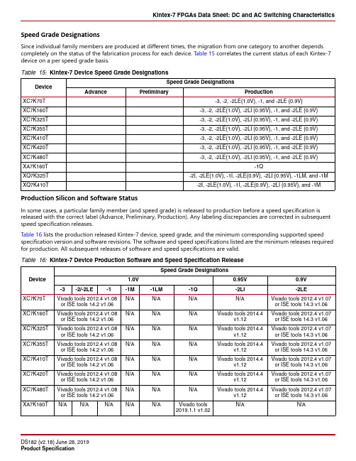
Speed Grade Designations
Since individual family members are produced at different times, the migration from one category to another depends completely on the status of the fabrication process for each device. Table 15 correlates the current status of each Kintex-7 device on a per speed grade14.5 v1.04
- 1、下载文档前请自行甄别文档内容的完整性,平台不提供额外的编辑、内容补充、找答案等附加服务。
- 2、"仅部分预览"的文档,不可在线预览部分如存在完整性等问题,可反馈申请退款(可完整预览的文档不适用该条件!)。
- 3、如文档侵犯您的权益,请联系客服反馈,我们会尽快为您处理(人工客服工作时间:9:00-18:30)。
ACEx™ Bottomless™ CoolFET™ CROSSVOLT™ DenseTrench™ DOME™ EcoSPARK™ E2CMOSTM EnSignaTM FACT™ FACT Quiet Series™
DISCLAIMER
FAST FASTr™ FRFET™ GlobalOptoisolator™ GTO™ HiSeC™ ISOPLANAR™ LittleFET™ MicroFET™ MICROWIRE™ OPTOLOGIC™
Value
-65 to +200 -65 to +175 250 1.67 20 150
Units
O O
C C
mW mW/OC V mA
Note 1: These ratings are limiting values above which the serviceability of any semiconductor device may be impaired
0.050 (1.270)
MAXIMUM SEE NOTE 1 BELOW
0.097 (2.464) Diameter 0.093 (2.362)
NOTE 1: LEAD DIAMETER NOT CONTROLLED IN THIS ZONE TO ALLOW FOR FLASH, LEAD FINISH BUILD-UP, & MINOR IRREGULARITIES OTHER THAN SLUGS.
nA uA mV mV mV mV mV V ps
VR = VR = IF IF IF IF IF IF = = = = = =
TRR CT
Reverse Recovery Time
IF= IR = 10 mA IRR = 1.0 mA RLoop = 100 Ohm VR = 0 V, f = 1.0 MHz
DO-7 PACKAGE
Electrical Characteristics SYM BV IR VF
TA = 25OC unless otherwise noted
CHARACTERISTICS Breakdown Voltage Reverse Leakage Forward Voltage
MIN 30
元器件交易网
FDH700
ULTRA FAST DIODE
DISCRETE POWER AND SIGNAL TECHNOLOGIES
Information Only Data Sheet
FINAL REVERSE CURRENT & FORWARD VOLTAGE LIMITS MIGHT BE INCREASED SLIGHTLY
DO-35 PACKAGE
Fairchild Semiconductor's Criteria
11-MAR-97
元器件交易网
FD700
Ultra Fast Diode Diode
DISCRETE POWER AND SIGNAL TECHNOLOGIES
Absolute Maximum Ratings (note 1) Parameter
DO-7 PACKAGE
Fairchild Semiconductor's Criteria 13-APR-93
元器件交易网
TRADEMARKS
The following are registered and unregistered trademarks Fairchild Semiconductor owns or is authorized to use and is not intended to be an exhaustive list of all such trademarks.
LIFE SUPPORT POLICY FAIRCHILD’S PRODUCTS ARE NOT AUTHORIZED FOR USE AS CRITICAL COMPONENTS IN LIFE SUPPORT DEVICES OR SYSTEMS WITHOUT THE EXPRESS WRITTEN APPROVAL OF FAIRCHILD SEMICONDUCTOR CORPORATION. As used herein: 2. A critical component is any component of a life 1. Life support devices or systems are devices or support device or system whose failure to perform can systems which, (a) are intended for surgical implant into be reasonably expected to cause the failure of the life the body, or (b) support or sustain life, or (c) whose support device or system, or to affect its safety or failure to perform when properly used in accordance with instructions for use provided in the labeling, can be effectiveness. reasonably expected to result in significant injury to the user. PRODUCT STATUS DEFINITIONS Definition of Terms Datasheet Identification Advance Information Product Status Formative or In Design Definition This datasheet contains the design specifications for product development. Specifications may change in any manner without notice. This datasheet contains preliminary data, and supplementary data will be published at a later date. Fairchild Semiconductor reserves the right to make changes at any time without notice in order to improve design. This datasheet contains final specifications. Fairchild Semiconductor reserves the right to make changes at any time without notice in order to improve design.
0.287 (7.290) 0.265 (6.731)
"C" BEND SPRING
SOLDER PREFORM Sb/Sn (5% - 10% Sb) BORATED (ALLOY 42) DUMET COMFAB STUDSEAL (FIRST SEAL)
1.110 (28.194) 1.085 (27.559)
Value
-65 to +200 -65 to +175 250 1.67 20 150
Units
O O
C C
mW mW/OC V mA
Note 1: These ratings are limiting values above which the serviceability of any semiconductor device may be impaired
nA uA mV mV mV mV mV V ps
VR = VR = IF IF IF IF IF IF = = = = = =
TRR CT
Reverse Recovery Time
IF= IR = 10 mA IRR = 1.0 mA RLoop = 100 Ohm VR = 0 V, f = 1.0 MHz
0.500 Minimum 12.70 Typ 1.000 CATHODE BAND LOGO FD H7 00 0.022 (0.558) Diameter 0.018 (0.458) Typ 20 mils 0.200 (5.08) 0.120 (3.05)
TA = 25OC unless otherwise noted
Absolute Maximum Ratings (note 1) Parameter
Storage Temperature Maximum Junction Temperature Total Power Dissipation at 25OC Derate above 25OC Working Inverse Voltage DC Forward Current
Storage Temperature Maximum Junction Temperature Total Power Dissipation at 25OC Derate above 25OC Working Inverse Voltage DC Forward Current
TA = 25OC unless otherwise noted
FDH700 - Rev. A
Diode Capacitance
1.5
pF
© 1999 Fairchild Semiconductor Corporation
元器件交易网
