日本富士FUJI信号隔离器PWBPD
FUJI XP242E贴片机操作规程MPS-0030
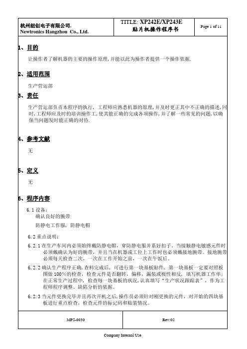
6 6.4.8显示出[主画面]。
6.5关机:6.5.1选择[主画面]的[注册]键。
显示出注册的信息。
6.5.2选择[OK]键,机器进入关机步骤。
6.5.3选择显示屏上的[关机]键切断主电源。
6.6机器的紧急停止:6.6.1选择机器的任何一个[紧急停止]按钮,切断伺服系统的200V电源,机器立即停止运转。
6.6.2要重新开始运转机器时,首先打开[紧急停止]按钮,然后请依次选择[运转准备]按钮和[启动]按钮。
6.7生产程序的选择:6.7.1在[主画面]上,顺序按下[生产],[选择程序]键后显示出[选择程序]对话框。
6.7.2选择生产中使用的程序。
选择[读入]键,读取所选择的程序。
在画面上方的任务栏上会显示装载完毕的程序名,表示该程序被激活。
6.8生产模式的设定:在[主画面]里选择[维修保养A]键和[动作条件设定]键,显示出[动作条件设定]画面。
生产模式有[生产],[空转1],[空转2],[传送]4种。
6.8.1生产:实际生产中使用的模式。
选择此模式,机器进行元件的吸取和影像处理以及元件的贴装。
6.8.2空转1:选择此模式时,吸嘴移到元件的吸取位置,进行实际的送料动作。
为了防止元件散落,事先从MFU及料盘单元上拆除供料器和料盘。
6.8.3空转2:选择此模式时,吸嘴移到元件的吸取位置,但不进行实际的送料动作。
6.8.4传送:选择此模式时,机器只作为搬运轨道用来将电路板传送到生产线上的下一道工序的机器上。
6.9动作模式的设定:从[主画面]中依次选择[维修保养A],[动作条件设定]键,显示出[动作条件设定]画面。
动作模式有[自动],[半自动],[暂停]3种。
6.9.1自动:实际生产时选择。
选择该模式后,连续执行程序的各个顺序。
6.9.2半自动:在试运转时选择。
选择该模式后,按程序的1个顺序进行执行。
6.14料盘信息:6.14.1在[主画面]上依次选择[生产],[料盘信息],进入[料盘信息]画面。
6.14.2 NO.表示供料平台/料站号COMMENT:表示料站注解吸取位置:表示元件的吸取位置6.14.3各料站的表示颜色:红色:原始料站蓝色:次料站黑色:生产中不使用的料站6.15运转中的画面显示:在[主画面]中依次选择[生产]和[顺序],使机器处于等待[启动]状态,选择[启动]按钮后开始生产。
XPF规格书简体

-4-
XPF-030706ZS
1.概 要
1.2.4
对应多种多样的元件
自动更换头有“旋转自动更换头”和“单吸嘴”可以根据贴装元件的种类 进行自动更换。另外,由于还可以对应”点胶自动更换头”所以可以不降 低生产线效率而最大限度的活用工作头的能力。
□10mm
□10mm
□10mm □10mm
2)-3 用2个φ5.0mm的吸嘴贴装20×20mm以内的元件 对于超过□10mm的元件,为了避免元件与吸嘴干涉对于φ3.7mm以上的 吸嘴只安装在上下的吸嘴位置(吸嘴号码1,7)。
□20mm
□20mm
-6-
XPF-030706ZS
1.概 要
1.2.4.2 单吸嘴
-8-
XPF-030706ZS
1.概 要
1.2.5
引脚浮起检测(选项)
可以用独创的光学系统和影像处理对QFP、VQFP、SOIC、接插件等引脚 元件的引脚浮起进行检查。
元件尺寸
最大45mm×150mm
元件高度※1
最大20.0mm为止或者最大15.0mm
每边的引脚根数
3根以上~128根以下
引脚间距
0.30mm以上
1) 超高速吸嘴更换系统
吸嘴的更换采用独创的”双真空吸嘴”系统可 以高速完成,即使是使用多种吸嘴因更换而造 成的损耗时间也只有一点点。
吸嘴头
吸嘴 元件
2) 双真空吸嘴和机械夹头(与XP-243E通用)
通过对应双真空吸嘴(标准吸嘴・长孔吸嘴・带有橡皮垫吸嘴)和机械夹 头,可以贴装各种元件。
<标准吸嘴>
·完全的单供料器 ·运转中可以自由拔插供料器 ·通过供料器ID系统实现防止错置功能 ·料带拼接容易 ·纸、嵌入式、料带厚度、送出间距的变更自由 ·与NXT & AIM共用
Fuji设备操作说明

SV
Fuji设备操作 Fuji设备操作
AMD 钟佰强 2010.03.24
FUJI 线SMD2⁄SMD3操作书 操作书
一. GL5⁄GL541点胶机
(一).开机
DESAY
SV
把电源拔到“ON”状态下,按下“POWER ON”按钮(解开紧急制动按钮“EMERGENCY STOP”, 按下“RESET”后消除所有故障后显示屏显示“Machine not Eere Set”(机器没有设置零点),按下 开始键“Press Start,”此时按下在闪烁的“START”按钮进行零点设置,完成以上的动作显示屏会显 示机器的初始状态为: AUTO STEP LOADER 送板(F3) PROGRAM 程序(F4) SET 设置(F5) RETURN 返回(F6) 自动(F1) 单步(F2) (二).关机 生产完成后,按下紧急制动“EMERGENCY STOP”,再按下“POWER OFF”后将电源拔到 “OFF”状态,此时关机完成. (三).自动生产 在初始状态下按AUTO(F1)显示屏显示为: × F1 × F2 × F3 SEQ. NO 步骤(F4) MODE 模式(F5) RETURN 返回(F6)
DESAY
三. FUJI IP1多功能贴机 多功能贴机 (一).开机
SV
把电源拔到“ON”状态下,按下“POWER ON”按钮(解开紧急制动按钮“EMERGENCY STOP”, 按下“RESET”后消除所有故障后显示屏显示“Machine not Eere Set”(机器没有设置零点),按下 开始键“Press Start,”此时按下在闪烁的“START”按钮进行零点设置,完成以上的动作显示屏会显 示机器的初始状态为: AUTO STEP LOADER 送板(F3) PROGRAM 程序(F4) SET 设置(F5) RETURN 返回(F6) 自动(F1) 单步(F2)
富士FUJI 标准IGBT(1MBI、2MBI、6MBI),智能IPM(6MBP、7MBP、7MBR)
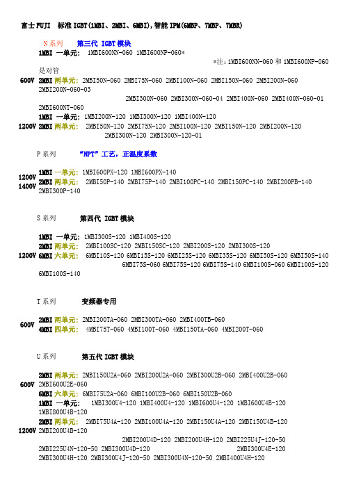
富士FUJI 标准IGBT(1MBI、2MBI、6MBI),智能IPM(6MBP、7MBP、7MBR) N系列第三代 IGBT模块600V 1MBI 一单元: 1MBI600NN-060 1MBI600NP-060**注:1MBI600NN-060和1MBI600NP-060是对管2MBI两单元: 2MBI50N-060 2MBI75N-060 2MBI100N-060 2MBI150N-060 2MBI200N-0602MBI200N-060-032MBI300N-060 2MBI300N-060-04 2MBI400N-060 2MBI400N-060-01 2MBI600NT-0601200V 1MBI 一单元: 1MBI200N-120 1MBI300N-120 1MBI400N-1202MBI两单元: 2MBI50N-120 2MBI75N-120 2MBI100N-120 2MBI150N-120 2MBI200N-120 2MBI300N-120 2MBI300N-120-01P系列“NPT”工艺,正温度系数1200V 1400V 1MBI一单元: 1MBI600PX-120 1MBI600PX-1402MBI两单元: 2MBI50P-140 2MBI75P-140 2MBI100PC-140 2MBI150PC-140 2MBI200PB-140 2MBI300P-140S系列第四代 IGBT模块1200V 1MBI 一单元: 1MBI300S-120 1MBI400S-1202MBI两单元: 2MBI100SC-120 2MBI150SC-120 2MBI200S-120 2MBI300S-1206MBI六单元: 6MBI10S-120 6MBI15S-120 6MBI25S-120 6MBI35S-120 6MBI50S-120 6MBI50S-140 6MBI75S-060 6MBI75S-120 6MBI75S-140 6MBI100S-060 6MBI100S-1206MBI100S-140T系列变频器专用600V 2MBI两单元: 2MBI200TA-060 2MBI300TA-060 2MBI400TB-0604MBI四单元: 4MBI75T-060 4MBI100T-060 4MBI150TA-060 4MBI200T-060U系列第五代IGBT模块600V 2MBI两单元: 2MBI150U2A-060 2MBI200U2A-060 2MBI300U2B-060 2MBI400U2B-060 2MBI600U2E-0606MBI六单元: 6MBI75U2A-060 6MBI100U2B-060 6MBI150U2B-0601200V 1MBI 一单元: 1MBI300U4-120 1MBI400U4-120 1MBI600U4-120 1MBI600U4B-120 1MBI800U4B-120 2MBI两单元: 2MBI75U4A-120 2MBI100U4A-120 2MBI150U4A-120 2MBI150U4B-120 2MBI200U4B-120 2MBI200U4D-120 2MBI200U4H-120 2MBI225U4J-120-50 2MBI225U4N-120-502MBI300U4D-120 2MBI300U4E-120 2MBI300U4H-120 2MBI300U4J-120-502MBI300U4N-120-50 2MBI400U4H-1202MBI450U4E-120 2MBI450U4J-120-50 2MBI450U4N-120-506MBI六单元: 6MBI35U4A-120 6MBI50U4A-120 6MBI75U4A-120 6MBI75U4B-1206MBI75UC-120 6MBI100U4B-120 6MBI100UC-120 6MBI150U4B-120 6MBI225U4-120 6MBI300U4-1206MBI450U4-1201700V 2MBI两单元: 2MBI100U4H-170 2MBI150U4H-170 2MBI200U4H-170 2MBI300U4H-1702MBI400U4H-1706MBI六单元: 6MBI75U4B-170 6MBI100U4B-170 6MBI150U4B-170 6MBI225U4-170 6MBI300U4-170 6MBI450U4-170大电流等级1200V1MBI 一单元: 1MBI1200U4C-120 1MBI1600U4C-120 1MBI2400U4D-120 1MBI3600U4D-120 2MBI两单元: 2MBI600U4G-120 2MBI800U4G-120 2MBI1200U4G-1201700V1MBI 一单元: 1MBI1200U4C-170 1MBI1600U4C-170 1MBI2400U4D-170 1MBI3600U4D-170 2MBI两单元: 2MBI600U4G-170 2MBI800U4G-170 2MBI1200U4G-170智能IGBT模块(IPM)一、工业级IPM:适用于变频空调,伺服控制等,内设欠压、过热、过流保护功能,开关频率最大20kHZ600V电压6MBP六单元:6MBP15RH060 6MBP20RH060 6MBP30RH060二、R系列IPM:(适用于通用变频器等,内设欠压、过热、过流保护功能)600V 电压6MBP六单元:6MBP20RTA060 6MBP50RA060 6MBP75RA060 6MBP100RA060 6MBP150RA060 6MBP200RA060 6MBP300RA060 6MBP50RTB060 6MBP50RTJ060 6MBP75RTB0606MBP75RTJ060 6MBP100RTB060 6MBP100RTJ060 6MBP150RTB060 6MBP150RTJ060 7MBP 七单元:7MBP50RA060 7MBP75RA060 7MBP100RA060 7MBP150RA060 7MBP200RA060 7MBP300RA060 7MBP50RTB060 7MBP50RTJ060 7MBP75RTB060 7MBP75RTJ0607MBP100RTB060 7MBP100RTJ060 7MBP150RTB060 7MBP150RTJ0601200V 电压6MBP六单元: 6MBP15RA120 6MBP25RA120 6MBP50RA120 6MBP50RJ120 6MBP75RA120 6MBP75RJ120 6MBP100RA120 6MBP150RA1207MBP 七单元:7MBP25RA120 7MBP25RJ120 7MBP50RA120 7MBP50RJ1207MBP75RA120 7MBP75RJ120 7MBP100RA120 7MBP150RA120PIM(智能功率集成模块)含整流桥七单元600V电压7MBR20SC060 7MBR30SA060 7MBR30SC060 7MBR50SA060 7MBR50SB060 7MBR50SC060 7MBR75SB060 7MBR75SD060 7MBR100SB060 7MBR100SD0601200V电压7MBR10SA120 7MBR10SC120 7MBR15SA120 7MBR15SC120 7MBR25SA120 7MBR25SC120 7MBR35SB120 7MBR35SD120 7MBR50SB120 7MBR50SD1201400V电压7MBR10SA140 7MBR15SA140 7MBR25SA140 7MBR35SB140 7MBR50SB140。
富士FRN5.5G11S-4CX说明书

低噪声高性能多功能变频器富士电机机器制御株式会社动态转矩矢量控制动态转矩矢量控制是一种先进的驱动控制技术。
控制系统高速计算电动机驱动负载所需功率,最佳控制电压和电流矢量,最大限度地发挥电动机的输出转矩。
●按照动态转矩矢量控制方式,能配合负载实现在最短时间内平稳地加减速。
●使用高速CPU 能快速响应急变负载和及时检知再生功率,设有控制减速时间的再生回避功能,实现无跳闸自动减速过程。
●采用富士独自开发的控制方式,在0.5Hz 能输出200%高起动转矩(≤22kW)。
* 30kW 以上时为180%。
高性能和多功能的理想结合动态转矩矢量控制能在各种运行条件下实现对电动机的最佳控制。
●使用PG 反馈卡(选件)构成带PG 反馈的矢量控制系统, 实现更高性能、更高精度的运行。
·速度控制范围: 1 : 1200·速度控制精度: ±0.02%·速度响应 : 40Hz带PG反馈更高性能的控制系统1电动机低转速时脉动大大减小●采用动态转矩矢量控制,结合富士专有的数字AVR,实现电动机低转速(1Hz)运行时的转速脉动比以前机种减小 1/2以上。
新方式在线自整定系统●在电动机运行过程中常时进行自整定,常时核对电动机特 性变化,实现高精度速度控制。
●第2电动机亦有自整定功能。
1台变频器切换运行2台电 动机时,保证2台电动机都能高精度运行。
优良的环境兼容性●采用低噪声控制电源系统,大大减小对周围传感器等设 备的噪声干扰影响。
●标准装有连接抑制高次谐波电流的DC 电抗器端子。
●连接选件EMC 滤波器后,能符合欧洲EMC 指令。
节能功能的提高●标准设有风机、泵等最佳自动节能运行模式。
采用使电动 机损耗降至最小的新控制方式,取得更好的节能效果。
●标准设有复写功能,能容易地将1台变频器的功能码数 据复写至其他变频器。
●显示器标准可选择3种语言(中文、英文和日文),便於 国内外配套使用。
●可简单地由键盘面板或外部接点信号进行点动(JOG)运 行操作。
富士电机 FCX-A II 系列变送器 说明书

使用说明书FCX-A Ⅱ系列变送器(PROFIBUS-PA 型)型号: FDA FDW FDB FDX FDC FDY FDD FDE FDGINF-TN4FCXA2PB-C······R V T W9th /INF-TN4FCXA2PB-Ci前言承蒙您购买富士FCX-A Ⅱ系列变送器(PROFIBUS-PA 型),深表感谢。
制 造 商 :富士电机计测仪表株式会社型 号 :见本体上的铭牌(参见第iv 页)制造日期 :见本体上的铭牌制 造 国 :日本发 行 ................. 2007-06• 请仔细阅读本使用说明书、在充分理解其内容之后再进行FCX-A Ⅱ系列变送器的安装、操作和维护。
• 本变送器的规格会因为产品改进而变更,恕不事先通知,敬请谅解。
• 严禁擅自改装本变送器。
若因擅自改装而引发的事故,本公司概不负责。
• 本使用说明书请由实际使用本变送器的人员保管。
• 阅读后,请将本使用说明书保存在使用者随时可以查阅之处。
• 请务必确保将本使用说明书交付给最终使用者。
• 有关详细规格和外形尺寸图,请参见别册的规格书。
本产品性能符合欧洲EMC 指令“Electromagnetic Compat-ibility Directive 89/336/EEC ”以及“Equipment and pro-tective systems intended for use in potentially explosive atmospheres Directive 94/9/EC ”标准的要求。
具体内容记载于工艺结构文件No.TN513035。
其适用标准如下。
EN 61326: 1997 Class A EN 61326: 1997 Annex A© 富士电机系统株式会社 2007安全注意事项使用前请务必认真阅读“安全注意事项”,确保正确使用。
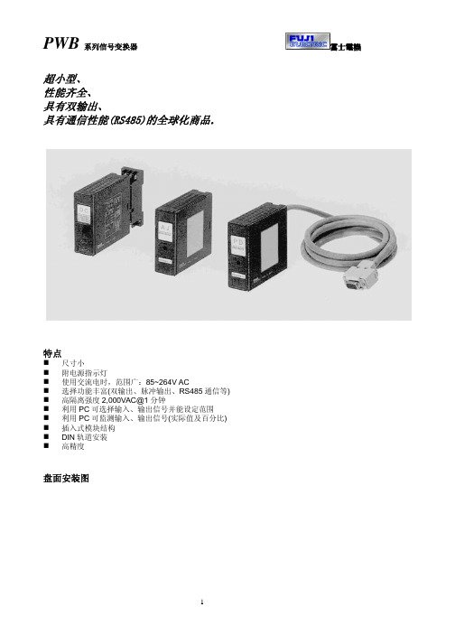
日本富士FUJI信号隔离器PWB介绍
1
PWB 系列信号变换器
类型一览表
类型
1
直流变换器
2
直流变换器(高速型)
3
交流变换器(1 输出)
4
交流变换器(可带双输出)
5
测速发电机变换器
6
热电偶变换器
7
热电阻变换器
8
电位计变换器
9
慢速频率变换器
10
信号分配器
11
反向变换器
12
直流报警器
13
简易设定器
14
智能设定器
బɻཥዚ
型号
输入
PWBDC 1~5V、0~10V、0~5V PWBHS 0~20MA、4~20MA
PWBDY 4~20MA(DC24~28V)
PWBRV
PWBAS PWBAJ PWBPD
1~5V、0~10V、 0~5VDC 4~20MA
第一输出
1~5V 0~5V 0~10V 0~20MA 4~20MA
5~1V 5~0V 10~0V 20~0MA 20~4MA 继电器
第二输出
1~5V 4~20MA RS485
页数 3 4 5 6 7
8
注: 9
PWBHS
PWBAC 10
PWBTG 11
PWBAS
除外
12
ቤተ መጻሕፍቲ ባይዱ
13
14 15 16
通用技术规格
绝缘电阻 绝缘强度
辅助电源
项目
输入、输出、电源、接地之间 第一输出、第二输出之间 交流 直流
消耗功率、消耗电流
使用温度、湿度范围 零点调整范围 量程调整范围 外形尺寸 重量
技术规格
2
PWBAC PWBAU
富士变频器接线图FRENICe

*12是控制印刷电路板上的各种切换开关,可设定变频器的动作。
*3即使变频器的主电源切断,也希望保持保护功能共作时的整体警报信号时,或希望操作面板进行显示时,请把本端子连接到电源上。即使不向该端子提供电源输入,变频器也可以运转。
*4通常不需要连接。高功率因子电源感应PWM转换器:与RHC系列(以下称为PWM转换器)组合时使用。
*5连接直流电抗器(DCR)选配件时,请拆下端子P1-P(+)间的短路棒后再进行连接。
富士变频器接线图FRENIC-MEGA
*1在变频器输入侧(初级侧)有配线保护,因此,请安装各变频器推荐的配线用断路器(MCCB)或漏电断路器(ELCB)(带过电流保护功能)。请勿使用推荐功率以上的断路器。
*2 MCCB或ELCB是在从另外的电源别离变频器时使用的,因此,根据需要,请在各个变频器上设置推荐的电磁接触器(MC)。此外,把MC或螺线管等线圈设置在变频器的附近时,请并列与浪涌吸收器相连接。
*8是电机的接地用的端子。请根据需要连接。
*9在控制信号线中,请使用双绞线或屏蔽线。屏蔽线请接地。为了防止噪音导致的误动作,请尽量与主电路配线分隔开,切勿放入同一个电缆槽内。(建议距离10cm以上。)出现交叉时,请与主电路配线尽可能垂直相交。
*10在端子FWD、REV以及X1~X9(数字输入),端子Y1~Y4(晶体管输出),端子Y5A/C,30A/B/C(接点输出)中记载的各种功能,显示的是出厂时所赋予的功能。
*6适用电机的输出功率为75kW以上时,请务必连接直流电抗器(DCR)选配件。
并且,电源变压器的功率为500kVA以上且是变频器额定功率的10倍以上时,及在同一电源系统“有半导体负荷时〞,请连接直流电抗器(DCR)
富士电机说明书

(6) 外 壳 颜 色:红 ( 主体部分 )、黑 ( 配线盘、基座 )
(7) 保 护 结 构
· 主 体 部:相当于 IP20 ( 上下面带槽 )
· 配 线 盘:相当于 IP00、
可安装选配的端子罩
8. 正常工作条件
(1) 环境温度【注】 :-10~50°C 【注】“环境温度”是指在设置本模块的设备 或控制柜内,本模块底面处的温度。
2
(2) 端 口 数:1 个端口 (3) 通信、同步方式:4 线式 半双工 起止同步式 (4) 通 信 速 度:9.6k、19.2k、38.4k、57.6k、115.2列 1000m 以内
MELSEC-A 系列 500m 以内 MELSEC-FX 系列 500m 以内 (6) 推 荐 电 缆:KFPEV-SB 2P 0.5sq
系统规格
1. 产 品 型 式 :多回路 · 模块型温度控制器
2. 构 成 模 块 :
1) 模拟式模块:合计最多 16 台
a) 控制模块〔4 回路〕
b) 扩展输入输出 ( 模拟式 ) 模块
- 模拟输入输出 〔输入、输出各 4 点〕
- 模拟输入
〔输入 4 点〕
- 模拟输出
〔输出 4 点〕
2) 扩展输入输出 ( 数字式 ) 模块:最多 16 台
前的数据 ( 重写次数 10 万次 )
6. 自诊断
· 方 式:由看门狗定时器监视程序的异常
7. 结构
(1) 安 装 方 法:利用 DIN 槽轨安装在控制柜内,或用 M3
螺钉安装在墙壁上
(2) 外 形 尺 寸:30(W)×100(H)×85(D)mm
( 凸出物、端子罩除外 )
(3) 重
量:约 200g
设定器
富士智能2021产品选型手册说明书

产品参数
外观颜色 机箱 面板 外观尺寸 工作温度 工作湿度 电源电压 通讯方式 主控器 最优识别距离 最大识别⻆度 语音对讲
香槟金 1.5mm钣金喷塑工艺 防眩光AG玻璃 380*344*1500mm -25℃〜70℃ ≤95%,无凝露 AC220V±10%50Hz TCP/IP通讯 ⻋牌识别控制器+无刷道闸控制器 3~5M ⻋牌与⻋道夹⻆≤45° 对讲距离≤1米
01
PRODUCTION
INTRODUCTION
COMPANY
公司简介
COMPANY INTRODUCTION
富士智能 ,成立于2004年 ,是智能出入口管理设备供 应商 、出入口管理系统解决方案提供商 ,智慧生态 环境 解 决方案专业供应商。
富 士 智 能,坚 持 以 人 为 本 、以 质 量 求 生 存 、以 服 务 创 市 场的信念,⻓期致力于智慧社区、智慧写字楼、智慧商业综 合体 、智慧景区、智慧园区 、智慧 校园 等 智慧生态 环境建 设 ,持续为数十万场景守好⻔ 、把好关 、收好费 ,已经成为 出入口智能管理和智慧城市生态环境建设的重要实践者、 推动者和引领者。
306 mm
230 mm
w w w. f u j i c a . c o m . c n
09
智能停⻋场管理系统
全球智慧城市生态环境建设重要实践者和引领者
FJC-TZ286
“金刚”机器人无人值守智慧⻋场管家
智慧通行卓然出众
产品特点
采用高强度新合金科技材料打造,无惧岁月洗礼,品质坚若磐石 17英寸LCD高亮触摸屏可显示停⻋时⻓、收费信息等,闲时可播放 广 告 或物管通知,为物业增值创收的同时提高管理效率 全方位出入方式:动态二维码、⻋牌识别等多种出入方式,安全、高效、 顺畅通行 多样化缴费形式:支持使用微信/支付宝/聚合码等扫码( 主扫/被扫)缴 费出场,支持使用现金缴费出场,可通过微信扫码找零 支持电子发票 一键问询:⻋主可通过远程协助按钮一键发起远程服务请求,与服务中 心进行双向语音通话,迅速获取人性化服务 远程对讲:支持服务中心主动远程连接现场,为⻋主提供协助服务 ,从 而打造无人值守的工作环境,彻底取代值守岗亭,降低人力成本 具备出色的系统稳定性、扩展性及实用性,适用于各种高端停⻋场
富士驱动器使用说明

富士驱动器使用说明作者:Admin 时间:2009-8-31 11:20:40 访问次数:1104用于隔离栅双极性晶体管(IGBT)的富士混合IC驱动器使用说明一、介绍隔离栅双极性晶体管(IGBT)正日益广泛地应用于小体积,低噪音,高特性的电源,逆变器,不间断电源(UPS)以及电机速度控制装置之中。
用于IGBT的富士混合IC驱动器吸取了IGBT的全部优点而开发。
二、特点∙不同的系列标准系列:最大10kHz运行高速系列:最大40kHz运行这些系列包括了全部IGBT产品范围∙内装用于高隔离电压的光耦合器:2500VAC一分钟∙单供电操作∙内装过流保护电路∙过流保护输出∙高密度安装的SIL封三、应用∙通用逆变器和电机控制∙伺服控制∙ 不间断电源(UPS )∙电焊机四、综合图表标准型 EXB850 EXB851 EXB850 EXB851注: 1.标准型:驱动电路信号延迟;大到 4μs (最大)2.高速型:驱动电路信号延迟;大到 1.5μs (最大)五. 尺寸,mmEXB850/EXB840EXB851/EXB841六 . 功能方框图①连接用于反向偏置电源的滤波电容③ 驱动输出⑤ 过流保护输出⑦ ⑧ 不接⑩ ⑾不接七. 额定参数和特性绝对最大额定值 (Ta=25o C)光耦合器输入电流I i 10 MA反向偏置输出电流I g2 PW=2μs duty at 0.05 or less 1.5 4.0 A工作表面温度T c -10 to +85oC∙推荐的运行条件供电电压V cc20 ± 1 V∙电特性(Ta=25o C)Turn-on time 1 导通时间t o n V cc=20V, IF=5mA 1.5 2.0 μsec过流保护电压t ocp V cc=20V, IF=5mA 7.5 7.5 V延迟t ALM V cc=20V, IF=5mA 1 1 μsec注:EXB850和EXB851(中速)需应用电路所示的IF过驱动。
富士变频器通信资料

一、概述........最大组成为1台主机能连接31台变频器——对应多点(据网友说,因为通信数据是16个字节<数据量比较大>,如果变频器台数增加到20台以上时,通信就没有那么稳定了<可能还需要关闭plc看门狗>)。
........据网友说,早期的G11不支持Modbus通讯,需要使用富士电机自己的协议——在其RS485接口手册上有详细的指令格式。
从06年开始,G11支持了Modbus通讯,通过用户在变频器参数U49中选择是采用富士电机协议FGI-Bus还是采用Modbus RTU协议。
........FRENIC 5000的11系列采用共同的通信协议,同样主机的程序能对11系列所有机种进行运行停止控制(参数可能随各机种有所不同)。
........采用固定长度的传送帧,使主机侧的程序容易开发。
........对应答速度有要求的运行命令和频率设定等使用选用传送帧,能缩短通信时间。
二、变频器参数设置........与通讯有关的主要参数设置如下所述(如果变频器通信过程中存在问题<无法按设定频率运行等>,怀疑其它参数还有问题,那么请将参数初始化<参数H03,同时按STOP键和上键设为1,再按FUNC/DATA 键确认>以后再来设定以下参数)。
........下例中,变频器地址设置为2,通讯格式设置为19200bps,8位数据,N无校验,2个停止位:H30:链接功能(通信功能);默认为0,现设置为3——RS485频率设定有效,运行命令有效;H31:RS485地址;默认为1,现设置为2;H32:故障处理;默认为0——立即Er8跳闸,采用默认值;H33:定时时间——通信故障后,在定时时间内继续运行;默认为2.0秒,采用默认值;H34:通讯传送速度(波特率);默认为1——9600 bit/s,现设置为0——19200 bit/s;H35:数据长度;默认为0——8位数据,采用默认值;H36:奇偶校验;默认为0——无奇偶校验,采用默认值;H37:停止位;默认为0——2个停止位,采用默认值;U49:RS485协议;默认为0——富士专用通讯协议FGI-Bus,采用默认值;F01:频率设定1;当该参数采用默认的0——键盘面板上下键设定(也就是数字设定)时,按变频器面板上的上下键更改设定频率显示“<数字设定Hz>LINK”,设定频率可以更改;当该参数设为11——数字输入或脉冲列输入设定(要用选件卡,详细请参阅选件卡使用说明书)时,按变频器面板上的上下键更改设定频率无效,显示“<远方设定有效>LINK”。
富士高速贴片机XP142规格说明书
紧凑式高速贴片机规 格 说 明 书MODEL X P - 1 4 2 ECNT-XP142-01S富士机械制造株式会社FUJI MACHINE MFG.CO.,LTD.初版 '03 年9月目录1.概 要1.1概 要_______________________________________11.2特 长_______________________________________12.要素2.1要素___________________________________________2 3.机器规格3.1基本规格_____________________________________33.2电路板搬运____________________________________43.3对象电路板____________________________________44.机器构成4.1ON-THE-FLY-VISION___________________________54.2吸嘴的种类____________________________________64.3吸嘴配置_____________________________________74.4供料平台的构成_______________________________105.控制5.1控 制______________________________________116.选项6.1选项分类____________________________________126.2选项内容____________________________________137.机器外观7.1外观图______________________________________177.2电源和空气入口_______________________________18<注意>本机器的正式型号为「XP-142E」。
(整理)富士FFA电梯控制系统使用说明书.

符号
显示色
灯亮条件
PWR
绿
电源指示灯,该CPU模块电源接通时灯亮(内部电源正常时)
RUN
绿
运行指示灯,该CPU模板运行时灯亮。(运行程序进行时)
停止时(也包括致命错误停止)灯灭。
ALM
红
错误指示灯,该CPU模板出现非致命错误或致命错误时灯亮。
*非致命错误:RUN灯亮/ALM灯亮
12.安全回路信号:常开信号,安全回路正常时应保持接通
13.门锁信号:门关好时信号接通
14.变频器检测信号:常闭信号,变频器正常时信号接通
15.运行信号:见注释4
16.关门延时信号:按钮信号
17.消防输入信号:开关常闭点信号,断开为选择消防功能
18.锁梯输入信号:开关常开点信号,接通信号为选择锁梯功能
较少的集成电路,加上全新的电梯控制编程方法,NW3P08-41C(42C)实现了简单则可靠、简单则低价、简单则易维护等设计要求。
微机各功能器件模块式集中布局,电路原理一目了然,具有极高的抗干扰能力。整板设计美观,接线方便。NW3P08-41C(42C)用户可自行编制电梯程序,并且三级密码保护功能。
由于有以上的优点,NW3P08-41C(42C)微机自推出以来赢得众多用户使用和好评,是一款性价比极高的微机。
第二章系统各器件介绍
2.1中央处理板(NW3P08-41C(42C))和I/O接口板(NW3W05606R)介绍
2.1.1中央处理板(NW3P08-41C(42C))和I/O接口板(NW3W05606R)端口定义
中央处理板(NW3P08-41C(42C))和I/O接口板(NW3W05606R)的各端口视图如下:
28.开关门限位开关保护功能
富士变频器使用说明
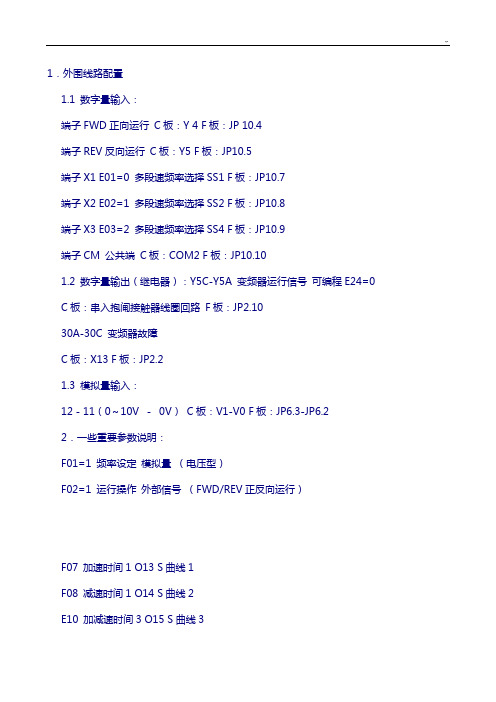
1.外围线路配置1.1 数字量输入:端子FWD正向运行C板:Y 4 F板:JP 10.4端子REV反向运行C板:Y5 F板:JP10.5端子X1 E01=0 多段速频率选择SS1 F板:JP10.7端子X2 E02=1 多段速频率选择SS2 F板:JP10.8端子X3 E03=2 多段速频率选择SS4 F板:JP10.9端子CM 公共端C板:COM2 F板:JP10.101.2 数字量输出(继电器):Y5C-Y5A 变频器运行信号可编程E24=0C板:串入抱闸接触器线圈回路F板:JP2.1030A-30C 变频器故障C板:X13 F板:JP2.21.3 模拟量输入:12 - 11(0~10V -0V)C板:V1-V0 F板:JP6.3-JP6.22.一些重要参数说明:F01=1 频率设定模拟量(电压型)F02=1 运行操作外部信号(FWD/REV正反向运行)F07 加速时间1 O13 S曲线1F08 减速时间1 O14 S曲线2E10 加减速时间3 O15 S曲线3bE11 加减速时间4 O16 S曲线4E12 加减速时间5 O17 S曲线5 数字量可调节参数值E13 加减速时间6 O18 S曲线6 模拟量不用,都为0E14 加减速时间7 O19 S曲线7E15 加减速时间8 O20 S曲线8O21 S曲线9O22 S曲线10F03 最高输出频率F04 基本频率此四个参数值须根据电机铭牌设F05 额定电压F06 最高输出电压F17 频率设定增益(模拟量)F18 频率偏置(模拟量)F26 载波频率15KHz 一般不调,仅当电机动作正常,但声音尖锐异常时可调整(≤15KHz)E33=1 过负载预报按输出电流预报E34: OL预报值额定电流150%**E37 过负载预报额定电流150%**C07 爬行速度C08 检修速度数字量可调节参数值C09 单层速度模拟量不用,都为0C10 双层速度C11 多层速度C33 模拟量输入滤波时间0.04P01 电机极数P=120f/N (f-电机额定频率;N-电机额定转速)一般情况,N >1000rpm,P=4极N≤1000rpm,P=6极P02 电机功率此两个参数值须根据电机铭牌设P03 电机额定电流P04 电机空载电流初始值设为p04的40%,自整定后自动生成O01=1 (闭环);0(开环)O03 编码器脉冲数(分频在PG卡上实现)O04 速度环P常数(高速时)O05 速度环I常数0.5O06 速度检测滤波常数0.003O07 速度环P常数切换频率1 5O08 速度环P常数切换频率2 10O09 速度环P常数(低速时)H03 数据初始化(一般不用)3. 特殊参数调试说明3.1 H03 数据初始化(一般不用)这个参数用法可参考第一章“3.1 A1-03=0 初始化”,与之用法类似。
隔离器工作原理

隔离器工作原理
隔离器是一种常见的电子器件,用于在电路中实现不同信号之间的电气隔离。
它的工作原理主要通过采用电磁感应或光电效应来实现。
电磁感应型隔离器是通过变压器的原理来工作的。
它由两个密封的线圈组成,分别称为输入线圈和输出线圈。
输入信号通过输入线圈产生一个磁场,这个磁场会在输出线圈中感应出一个相应的电压信号。
由于输入线圈和输出线圈之间没有物理连接,因此可以实现电气隔离。
光电型隔离器则利用光电效应来工作。
它由一个发光二极管和一个光敏二极管组成。
发光二极管将输入信号转化为光信号,并通过空气或光导纤维传递到光敏二极管。
光敏二极管根据接收到的光信号产生一个相应的电流,从而实现输入和输出信号的隔离。
隔离器的工作原理可以大大提高电路的稳定性和安全性。
它可以避免信号之间的相互干扰,防止高电压或高电流对低电压或低电流信号的影响。
此外,隔离器还可以保护人身安全,防止电流通过人体产生触电危险。
需要注意的是,在使用隔离器时,我们应该选择合适的隔离等级和参数,以确保电路的正常运行和安全性。
同时,隔离器的工作原理和性能也需要通过相关测试和验证来保证。
GTS-400-PV(G)-PCI系列运动控制器用户手册
富士通电子部件-接线器自动挡版(12V汽车电池,25A)系列名称FTR-G1 FTR-P3 FTR-

Fujitsu Components RELAYSAutomotive, Power, Signal, Solid StateContentProduct Line-UpAutomotive Relays Page4EV/PHV Relays Page10Power Relays Page13Signal Relays Page26Solid State Relays Page28Reference Page29About Page30Contact Page31Relays with this logo are available as “Glow Wire” versions. (-GW)These relays are IEC60335-1 compliant.Please refer to your supplier for more information or contact your local Fujitsu Office.For contact information, see the last page of this document, or https:///en/Page 3Page 4Series Name FTR-G1FTR-P3FTR-P5Description25A Compact Relay 25A Compact Relay 25A Low Noise Compact Relay Features■0.25mm contact gap■Average acoustic noise level 60dB @ 5cm ■No polarity on coil terminals ■0.25 & 0.6mm contact gap types ■THR type available ■High temp. types available(+125 o C) (THR)■Pin compatible w/ FTR-P5■No polarity on coil terminals ■Pin compatible wit FTR-P3 ■Average acoustic noise level 50dB @ 5cm ■No polarity on coil terminals Dimensions (W x L x H mm)6.6 x 13.7 x 13.57.2x17.4x13.5, (THR:7.2x17.4x14.1)9.7 x 20.4 x 16.7Weight (approx.)3.5 g 5.0 g 7.0 g Contact form1 c 1 c, (THR: 1a, 1c) 1 c Contact rating25A, 14VDC locked motor load 25A, 14VDC, locked motor load 25A, 14VDC, locked motor load Maximum carrying current25A 1 Hr 25A 1 Hr 25A 1 Hr Expected life onload example 14VDC, 25A Locked motor load100 x 103 ops. 14VDC, 25A, locked motor load 100 x 103 ops.14VDC, 25A, locked motor load 100 x 103 ops.Operating temperature-40 to +85 o C -40 to +85 o C / +125 o C (THR)-40 to +85 o C Coil voltage (DC)9 to 12 V 9 to 12 V 9 to 12 V Nominal coil power0.640 W 0.6 W / 0.8 W 0.45 to 0.455 W Dielectric strength (1 min.)Open contacts: 500VAC Coil and contacts: 500VAC Open contacts: 500VAC Coil and contacts: 500VAC Open contacts: 500VAC Coil and contacts: 500VAC Mounting / enclosureThrough hole / plastic seal Through hole / plastic seal Through hole / plastic sealTerminal layout(bottom view)1a does not carry #3 contactPage 5Series Name FTR-P4FTR-P2FTR-P7Description25A H-bridge Relay 25A Low Noise H-bridge Relay 25A Low Noise Compact Automotive Relay Features■0.25 contact gap types■Pin compatible with FTR-P2 ■No polarity on coil terminals■Pin compatible with FTR-P4 ■Average acoustic noise level 50dB @ 5cm ■No polarity on coil terminals ■0.3 mm contact gap ■Average acoustic noise level 45db @ 5cm ■No polarity on coil terminalsDimensions (W x L x H mm)14.2 x 17.4 x 13.516.5 x 21.0 x 18.017.0 x 20.8 x 14.0Weight (approx.)10.0 g 13.0 g 7.0 g Contact form1 cx2 (H-bridge)1c x 2 (H-bridge) 1 c Contact rating25A, 14VDC, locked motor load 25A, 14VDC, locked motor load 25A, 14VDC locked motor load Maximum carrying current25A 1 Hr 25A 1 Hr 25A 1 Hr Expected life on load example 14VDC, 25A, locked motor load100 x 103 ops.14VDC, 25A, locked motor load 100 x 103 ops.14VDC, 25A, locked motor load 100 x 103 ops.Operating temperature-40 to +85o C -40 to +85o C -40 to +85 o C Coil voltage (DC)9 to 12 V 9 to 12 V 12 V Nominal coil power0.6 W 0.45 to 0.455W 0.554 W Dielectric strength (1 min.)Open contacts: 500VAC Coil and contacts: 500VAC Open contacts: 500VAC Coil and contacts: 500VAC Open contacts: 500VAC Coil and contacts: 500VAC Mounting / enclosureThrough hole / plastic seal Through hole / plastic seal Through hole / plastic sealTerminal layout(bottom view)Page 6Series Name FBR51L FBR53FTR-G3 Description25A Dual coil Latching CompactAutomotive Relay30A Compact Automotive Relay30A Compact RelayFeatures■Dual coil latching■THR type available■Polarized coil terminals■THR type (-RW) available■60A inrush■No polarity on coil terminals■30A fuse capacity■THR type available■No polarity on coil terminalsDimensions (W x L x H mm)12.1 x 15.5 x 13.712.3 x 15.7 x 14.0 6.6 x 13.7 x 14.0Weight (approx.) 6.0 g 6.0 g 4.0 gContact form 1 c 1 form U 1 a, 1 cContact rating25A, 14VDC, locked motor load25A, 14VDC, resistive load30A, 14VDCMaximum carrying current30A 1Hr30A40.5A 30 minutesExpected life onload example14VDC, 25A, locked motor load200 x 103 ops. (-W1 type)50 x 103 ops. (E type)14VDC, 25A, resistive load100 x 103 ops.100 x 103 ops.Operating temperature-40 to +125 o C -40 to +125 o C -40 to +125 o CCoil voltage (DC)10 V9 to 12 V12 VNominal coil power 1.11 W0.556 to 0.6 W0.64 WDielectric strength (1 min.)Open contacts: 500VACCoil and contacts: 500VACOpen contacts: 500VACCoil and contacts: 500VACOpen contacts: 500VACCoil and contacts: 500VAC Mounting / enclosure Through hole / plastic seal Through hole / plastic seal Through hole / plastic seal Terminal layout(bottom view)1235641c contact formPage 7Series Name FBR53-HW FBR59-HW FTR-E1-HCDescription40A Compact Relay 45A/70A High Power Relay 60A compact relay Remarks■THR type (-RW) available■High power type■80A inrush ■No polarity on coil terminals■THR type (-RW) available ■High power type ■220A max. inrush ■No polarity on coil terminals ■No polarity on coil terminalsDimensions (W x L x H mm)12.3 x 15.7 x 14.015.0 x 20.0 x 16.828.3 x 43.6 x 26.8Weight (approx.)6.0 g 13.0 g 80.0 g Contact form1 form U 1 form U 1a (1 form X)Contact rating40A, 14VDC, resistive load 45A, 14VDC motor lock, 70A 14VDC resistive 60A 400VDC (at 60o C)Maximum carrying current40A 70A 1Hr 60A at 60o C Expected life on loadexample 14VDC, 40A, resistive load 100 x 103 ops.70A 14VDC, resistive 50 x 103 ops.500 x 103 ops.Operating temperature-40 to +125 o C -40 to +125 o C -40 to +60o C (at 60A)Coil voltage (DC)9 to 12 V 9 to 12V 12, 24V Nominal coil power0.855 to 0.862 W 0.45 to 0.477 W 1.2 W Dielectric strength (1 min.)Open contacts: 500VAC Coil and contacts: 500VAC Open contacts: 500VAC Coil and contacts: 500VAC Open contacts: 2,500VAC Coil and contacts: 5,000VAC MountingThrough hole / plastic seal Through hole / plastic seal Through hole / plastic sealTerminal layout(bottom view)124875 1 (+)2 (-)34Page 8Automotive relays (12V car battery)Series Name FTR-V1FTR-P3 (-06)FBR57 Description210A High Capacity LatchingRelay6A Compact Relay 12A High Power Relay Features■210A (@85°C)/120A(@125°C) continuouscurrent■Polarized coil terminals■For 24V battery applications■THR type available■No polarity on coil terminals■For 24V battery applications■70A inrush■No polarity on coil terminalsDimensions (W x L x H mm)52.8 x 84.5 x 24.77.2 x 17.5 x 14.114.4 x 20.0 x 16.2Weight (approx.)120 g 5.0 g9.4 gContact form1b 1 c 1 cContact rating Inrush 230A, 14VDCBreak 1A, 14VDC, dedicatedload6A, 28VDC12A, 28VDC, locked motor loadMaximum carrying current210A at 85o C20A 1 Hr40A 10 min. / 30A 1 Hr Expected life onload exampleInrush 230A, 14VDCBreak 1A, 14VDC120 x 103 ops.20VDC 6A resistive100 x 103 ops.28VDC, 12A, locked motor load100x103 ops.28VDC, inrush 16A/break 2.5A,free motor load500 x 103 ops.Operating temperature-40 to +125 o C-40 to +125 o C -40 to +85o CCoil voltage (DC)12V24V24 VNominal coil power28.8 W0.9W 1.5 WDielectric strength (1 min.)Open contacts: 500VACCoil and contacts: 500VACOpen contacts: 500VACCoil and contacts: 500VACOpen contacts: 500VACCoil and contacts: 500VAC Mounting / enclosure Plastic seal Through hole / plastic seal Through hole / plastic seal Terminal layout(bottom view)12345+ 4(+) 526 -3 (-)1Automotive (24V battery applications)Page 9Series Name FBR572 / 582 FBR59-HWDescription12/14A High Power Twin Relay 30A High Power Relay Features■For 24V battery applications■0.8/1.4mm contact gap■60A inrush ■No polarity on coil terminals■For 24V battery applications ■THR type available ■No polarity on coil terminalsDimensions (W x L x H mm)20.0 x 26.0 x 16.2 (FBR572)20.0 x 26.0 x 17.0 (FBR582)15.0 x 20.0 x 16.8 Weight (approx.)18.0 g 13.0 g Contact form1 c x2 1 form U Contact rating12A, 28VDC, locked motor load 30A 28VDC Maximum carrying current40A 2min.70A 1 Hr (@20o C)Expected life on load example 28VDC, 12A, locked motor load100 x 103 ops. (FBR572, 582)28VDC, inrush 15A/break 2.5A,free motor load500 x 103 ops. (FBR572)28VDC 20A resistive 100 x 103 ops. Operating temperature -40 to +85 o C-40 to +125 o C Coil voltage (DC)24 V12, 24 V Nominal coil power 1.5W / 3.4W1.2 W Dielectric strength (1 min.)Open contacts: 500VACCoil and contacts: 500VACOpen contacts: 500VAC Coil and contacts: 500VAC Mounting / enclosure Through hole / plastic seal Through hole / plastic sealTerminal layout(bottom view)Automotive relays (24V battery applications)124578Page 10EV/PHV relays (DC control)Series Name FTR-B3FTR-B4FTR-J2Description2A Low Profile Relay 2A Slim Type Relay 10A 450VDC Small High Voltage DC Relay Features■Space saving versions available■THT and SMT versions ■Polarity on coil terminals ■Space saving versions available ■THT and SMT versions ■Polarity on coil terminals ■Special arc extinguishing provision ■150A inrush per contact ■Polarity on coil terminalsDimensions (W x L x H mm)7.2 x 10.6 x 5.25 (SMT) 5.7 x 10.6 x 9.7 (SMT)23.5 x 24.0 x 27.0Weight (approx.)0.85g 1.0g 26.0g Contact form2c 2c 1a x 2Contact rating 0.3A 125VAC/1A 30VDC 0.3A 125VAC/1A 30VDC 10A 200VDC (NO contact usedindependently)10A 450VDC (2 contactsconnected in series)Maximum carrying current 2A 2A 12AMin. switching load (ref.)10mVDC 0.01mA 10mVDC 0.01mA 5VDC 100mAExpected life on loadexample100 x 103 ops.100 x 103 ops.10 x 103 ops.Coil voltage (DC)1.5 to 24V 1.5 to 24V 5 to 110V Nominal coil power0.14 to 0.23W 0.14 to 0.23W 1.06W (2 contacts connected in series)Surge strength2,500V 2,500V 10,000V Dielectric strength (1 min.)Open contacts: 1,000VAC Coil and contacts: 1,500VAC Open contacts: 1,000VAC Coil and contacts: 1,500VAC Open contacts: 1,000VAC Coil and contacts: 4,000VAC Safety standardsUL, CSA, BSI, FCC68, Telcordia, IEC60950-1UL, CSA, BSI, FCC68, Telcordia, IEC60950-1UL, VDE Mounting / EnclosureThrough hole or surface mount / plastic seal Through hole or surface mount / plastic seal Through hole/ flux proof Terminal layout(bottom view) (Bottom view)(Top view)(Bottom view)(Top view)Series Name FTR-E1Description 20A/30A, 450VDC High Voltage DC RelayFeatures■cULus recognized typesavailable■Polarized on coil terminals■No polarity on contactsDimensions (W x L x H mm)28.3 x 43.6 x 36.8Weight (approx.)75.0 gContact form1a (1 Form X)Contact rating20A 450VDC (20A type)30A 450VDC (30A type)Maximum carrying current40A (@ +85 o C)Min. switching load (ref.)6VDC, 1AExpected life on load example10 x 103 ops. (20A 450VDC)*5 x 10³ ops (30A 450VDC) ** with varistorCoil voltage (DC)12, 24VNominal coil power0.9WSurge strength-Dielectric strength (1 min.)Open contacts: 2,500VACCoil and contacts: 5,000VAC Safety standards-Mounting / Enclosure Through hole / plastic seal Terminal layout(bottom view)Series NameFTR-K1(-HT / -KW)FTR-K3 (-WG / -WS / -PV / -PS)FTR-K5Description 16A Plastic sealed 105o C type 25/32A Wide Contact Gap Relay 40A relay for on-board charger Features■UL TV-5 available ■5mm pitch■Creepage/clearance>10mm■No polarity on coil terminals■Conform to VDE0127■ 1.5mm or 1.8mm contact gap■No polarity on coil terminals■For 6.6kW standard charger ■Operable at up to 105o C■No polarity on coil terminalsDimensions (W x L x H mm)12.7 x 29.0 x 15.715.7 x 30.1 x 23.318.0 x 30.5 x 29.7Weight (approx.)13.0g 25.0 to 26.0g 39.0g Contact form 1a, 1c1a1aContact rating16A 250VAC/24VDC 25A/32A 250VAC 32A 250VACMaximum carrying current 20A25A, 32A 40A (at 105o C, 8mm 2 cable)Min. switching load (ref.)5VDC 100mA5VDC 100mA 6VDC 1AExpected life on load example10 x 103 ops. to 100 x 103 ops.100 x 103 ops. (25A)* 30 x 103 ops. (32A)** 1.5mm gap type1,000 ops. (plastic seal)30 x 103 ops. (flux proof)Coil voltage (DC) 5 to 110V 5 to 48V 5 to 24V Nominal coil power 0.4 to 0.43mW 0.78 to 1.4W0.9W Surge strength10,000V8,500VAC(25A), 6,000V (32A)-Dielectric strength (1 min.)Open contacts: 1,000VAC Coil and contacts: 5,000VAC Open contact 2,500VAC Coil and contacts: 5,000V (25A), 4,000V (32A)Open contacts: 1,000VAC Coil and contacts: 5,000VAC Safety standards UL, CSA, VDEUL, VDE, CQC-Mounting / Enclosure Through hole / plastic seal or flux proofThrough hole / plastic sealThrough hole /plastic seal or flux proofTerminal layout (bottom view)Orientation markOrientation markFTR-K1-AK FTR-K1-CK COMNO56784321NC COM NO 567843211234Power relays (3A ~ 5A)Series NameNYJYFTR-F3 (3A)Description 5A Slim Type Relay 3/5A Compact Relay 3A Slim Type RelayRemarks■Socket available (-NYP) ■Compliant to IEC61010-2-201 and 61131 reinforced insulation■Compatible with SN solid state relay■No polarity on coil terminals■Socket available (-P) ■Pin compatible with SJ solid state relay■No polarity on coil terminals■IEC60695-2-11 types (-GW) ■AgNi contacts■No polarity on coil terminalsDimensions (Wx L x H mm) 5.0 x 20.1 x 17.59.8 x 20.0 x 12.87.0 x 20.3 x 15.0Weight (approx.) 3.5 g 5.0 g 4.0 g Contact form 1 a1 a1 aContact rating (resistive load)5A, 250VAC/30VDC 3A, 250VAC/30VDC (3A type)5A, 250VAC/30VDC (5A type)3A, 125VAC/30VDC Maximum carrying current 5A5A5AMinimum switching load (ref.)5VDC, 1mA100m VDC 0.01mA (W)5VDC 10mA (G, HG)5VDC 100mA (R, HR)5VDC 10mAElectrical life (rated load)100 x 103 ops. (at 3A, 250VAC, 30VDC)50 x 103 ops. (at 5A, 250VAC,30VDC)100 x 103 ops.200 x 103 ops.Coil voltage (DC) 4.5 to 24 V 4.5 to 48 V 5 to 24 V Nominal coil power 0.12 W 0.2 to 0.36 W 0.2W Surge strength5,080 V4,000 V10,000 VDielectric strength (1 min.)Open contacts: 750VACCoil and contacts: 3,000VAC Open contacts: 750VACCoil and contacts: 2,000VAC Open contacts: 750VAC Coil and contacts: 4,000VAC Safety standards UL, CSAUL, CSAUL, CSA, VDE, CQCMounting / Enclosure Through hole / plastic sealThrough hole / plastic sealThrough hole / plastic seal or flux proofTerminal layout (bottom view)Series NameFTR-F3 (5A)FTR-F3 (5A TV rating)FTR-F3 (10A)Description 5A Slim Type Relay 5A Slim or Flat Type Relay 10A Slim Type Relay Remarks■IEC60335-1 types (-GW) ■AgNi contacts■No polarity on coil terminals■Right angle versions avail-able■TV-3 or TV-5 rating ■AgSnO2 contacts■No polarity on coil terminals■AgNi contacts■No polarity on coil terminalsDimensions (Wx L x H mm)7.0 x 20.3 x 15.07.0 x 20.3 x 15.0 (slim) 15.0 x 20.3 x 7.0 (flat)7.0 x 20.3 x 15.0 Weight (approx.) 4.0 g 6.0 g 4.0 g Contact form 1a1 a1 aContact rating (resistive load)5A, 250VAC/30VDC 5A, 250VAC/30VDC 10A, 250VAC Maximum carrying current 5A5A10AMinimum switching load (ref.)5VDC 10mA 5VDC 10mA 5VDC 100mAElectrical life (rated load)100 x103 ops.50 x 103 ops.50 x 103 ops. (flux proof type)10 x 103 ops (plastic sealed type)Coil voltage (DC) 5 to 24 V 3 to 24 V 5 to 24 V Nominal coil power 0.2W 0.28W 0.2 W Surge strength10,000 V10,000 V10,000 VDielectric strength (1 min.)Open contacts: 750VAC Coil and contacts: 4,000VAC Open contacts: 750VAC Coil and contacts: 4,000VAC Open contacts: 750VAC Coil and contacts: 4,000VAC Safety standards UL, CSA, VDE, CQC UL, CSA, VDEUL, CSA, VDE, CQCMounting / Enclosure Through hole / flux proofThrough hole / plastic sealThrough hole / plastic seal or flux proofTerminal layout (bottom view)1234COMNOOrientation mark(slim type)(flat type)2134NO COMSeries Name FTR-F3 (5A 1 transfer)FTR-MY FTR-F2 Description5A 1 TransferType Relay5A Slim Type Relay5A High profile RelayRemarks■ 1 form C type■AgNi contacts■No polarity on coil terminals ■Compliant to IEC61010-2-201, 61131-2 reinforcedinsulation■Conforms to ANSI/ISA12.12.01■Creepage, clearance>5.6mm■No polarity on coil terminals■TV-5 rated■High sensitive coil types■No polarity on coil terminalsDimensions (Wx L x H mm)7.0 x 23.4 x 15.0 5.0 x 20.0 x 12.011.0 x 24.0 x 25.0Weight (approx.) 6.0 g 2.5 g13.0 gContact form1c 1 a 1 aContact rating(resistive load)10A, 250VAC/30VDC5A, 250VAC/30VDC5A, 250VAC/30VDC Maximum carrying current5A5A5AMinimum switching load (ref.)5VDC 10mA 5VDC 1mA5VDC 100mAElectrical life (rated load)50 x 103 ops. 5 x 10³ ops.100 x 103 ops.Coil voltage (DC) 5 to 24 V 4.5 to 24 V 5 to 48 V (sensitive: 5 to 24 V) Nominal coil power0.36 W0.11 W0.25 to 0.53 WSurge strength10,000 V5,080 V10,000 VDielectric strength (1 min.)Open contacts: 750VACCoil and contacts: 4,000VAC Open contacts: 750VACCoil and contacts: 3,000VACOpen contacts: 1,000VACCoil and contacts: 4,000VACSafety standards UL, CSA, VDE, CQC UL, CSA, VDE, CQC UL, CSA, VDE, CQC Mounting / Enclosure Through hole / plastic seal Through hole / plastic seal Through hole / flux proofTerminal layout(bottom view)56Series NameJVFTR-F1 (5A)FTR-F1 (8A)Description 5A Medium Load Relay 2 poles, 5A Low Profile Relay 2 poles, 8A Low Profile Relay Remarks■High sensitive type available■No polarity on coil terminals■Pin compatible with VB se-ries■TV-3 rating available (2a) ■Clear cover available (-RG) ■Sensitive coil types■8A types FTR-F1R available■No polarity on coil terminals■Pin compatible with VB series■TV-3 rating available (2a) ■Clear cover available (-RG) ■Sensitive coil types available■No polarity on coil terminalsDimensions (W x L x H mm)10.0 x 17.5 x 12.512.8 x 29.0 x 16.512.8 x 29.0 x 16.5Weight (approx.) 4.3 g 12.0 g 12.0 g Contact form1 a2 a, 2 c2 a, 2 cContact rating (resistive load)5A, 250VAC/30VDC 5A, 250VAC/24VDC 8A, 250VAC/24VDC Maximum carrying current 5A7A8AMinimum switching load (ref.)5VDC, 100mA 5VDC 10mA 5VDC 10mA Electrical life (rated load)100 x 103 ops.100 x 103 ops.50 x 103 ops.Coil voltage (DC) 3 to 48 V(High sensitive: 3 to 24V) 1.5 to 110 V(High sensitive: 1.5 to 48V) 1.5 to 110 V(High sensitive: 1.5 to 48V)Nominal coil power 0.2 to 0.3 W 0.4 to 0.55 W 0.4 to 0.55 W Surge strength10,000 V10,000 V10,000 VDielectric strength (1 min.)Open contacts: 750VACoil and contacts: 5,000VAC Open contacts: 1,000VAC Coil and contacts: 5,000VAC Open contacts: 1,000VAC Coil and contacts: 5,000VAC Safety standards UL, CSA, VDE, CQC UL, CSA, VDE, CQC UL, CSA, VDEMounting / Enclosure Through hole / plastic sealThrough hole / plastic sealThrough hole / flux proofTerminal layout (bottom view)857421NONOCOMCOM87654321NO NOCOM COMNC NCOrientation markOrientation markFTR-F1A typeFTR-F1C type857421NONOCOMCOM87654321NO NOCOM COMNCNCOrientation markOrientation markFTR-F1A typeFTR-F1C typeSeries NameFTR-F1LFTR-LYJSDescription 2 poles 8A Low Profile Latching Relay 6A Slim Type Relay 8A Low Profile Relay Remarks■Latching relay ■ 1 and 2 coil types■Polarized coil terminals■Ultra slim■Socket type available■Right angle type available■Creepage/clearance >8mm■ 3.2 and 5 mm pitch types ■Creepage/clearance >8mm ■Au plated version available■No polarity on coil terminalsDimensions (W x L x H mm)12.8 x 29.0 x 16.5 5.0 x 28.0 x 15.0 (straight)10.0 x 29.0 x 12.5Weight (approx.)13.0 g 5.0 g 8.0 g Contact form2 a, 2 c1 a, 1 c1 a, 1 cContact rating (resistive load)8A, 250VAC/24VDC 6A, 250VAC/24VDC 8A, 250VAC/24VDC Maximum carrying current 8A6A10AMinimum switching load (ref.)5VDC 10mA 5VDC, 10mA (-V type) 5VDC 100mA (-Y , -E type)5VDC 100mA, 5VDC 10mA (3µAu)Electrical life (rated load)50 x 103 ops.30 x 103 ops. NC 50 x 103 ops. NO 20 x 103 ops. to 50 x 103 ops.(Depends on contact material)Coil voltage (DC) 5 to 24 V 5 to 60 V5 to 60 V Nominal coil power 0.4 to 0.6 W 0.17 W / 0.217 mW 0.22 to 0.29 W Surge strength10,000 V6,000 V10,000 VDielectric strength (1 min.)Open contacts: 1,000VAC Coil and contacts: 5,000VAC Open contacts: 1,000VAC Coil and contacts: 4,000VAC Open contacts: 1,000VAC Coil and contacts: 5,000VAC Safety standards UL, CSA, VDE, CQC UL, CSA, VDEUL, CSA, VDE, CQC Mounting / Enclosure Through hole / plastic sealThrough hole / plastic sealThrough hole / plastic sealTerminal layout (bottom view)1 N.O.5 COM.431 N.O.5 COM.43*857421NONOCOMCOM87654321NO NOCOM COMNCNCOrientation markOrientation markFTR-F1A typeFTR-F1C type**omitted on 1 form A type(straight)3(※)543 (*)21(right angle)(1 coil)Series NameJSLJS-KSFTR-H2Description 8A Low Profile Latching Relay 8A Low Profile High Inrush Relay 10A High Profile Relay Remarks■Latching type■ 1 and 2 coil types available ■ 3.2mm pitch■Creepage/clearance >8mm■Polarized coil terminals■1000W lamp load ■65A inrush ■5mm pitch■Creepage/clearance >8mm■No polarity on coil terminals■TV-5 rated■High sensitive types available■Creepage/clearance >6mm■No polarity on coil terminalsDimensions (W x L x H mm)10.0 x 29.0 x 12.510.0 x 29.0 x 12.511.0 x 24.0 x 25.0Weight (approx.)8.0 g 8.0 g 13.0 g Contact form1 a, 1 c1 a1 aContact rating (resistive load)8A, 250VAC/24VDC8A, 250VAC/24VDC10A, 250VAC/30VDCMaximum carrying current 10A10A10AMinimum switching load (ref.)5VDC 100mA 5VDC 100mA5VDC 100mAElectrical life (rated load)50 x 103 ops. 100k @ rated load25k @ lamp load (TV4)100 x 103 ops. @ rated load25 x 103 ops. (@ lamp load TV-5)Coil voltage (DC) 3 to 24 V5 to 60 VDC 5 to 48 V (High sensitive: 5 to 24V)Nominal coil power 0.22 to 0.25 (1coil), 0.48 (2 coils)0.22 to 0.29 W 0.25 to 0.53 W Surge strength10,000 V10,000 V10,000 VDielectric strength (1 min.)Open contacts: 1,000VAC Coil and contacts: 5,000VAC Open contacts: 1,000VAC Coil and contacts: 5,000VAC Open contacts: 1,000VAC Coil and contacts: 4,000VAC Safety standards UL, CSA, VDEUL, CSAUL, CSA, VDE, CQC Mounting / Enclosure Through hole / plastic sealThrough hole / plastic sealThrough hole / flux proofTerminal layout (bottom view)1 Set6 5 (-) +3 (+) -2 Reset1 Set65 (-) +3 (+) -2 Reset(a(a(a ommited on 1 a types1 N.O.5 COM.43Series Name FTR-J2Description10A, 450VDC Small HighVoltage DC RelayRemarks■Special arc extinguishing provision■150A inrush per contact■Polarized contact terminals■No polarity on coil terminalsDimensions (W x L x H mm)23.5 x 24.0 x 27.0Weight (approx.)26.0 gContact form1a x 2Contact rating (resistive load)10A, 200VDC (use NO contact independently)or 10A, 450VDC600VDC max. (2 contacts connected in series) Maximum carrying current12AMinimum switching load (ref.)5VDC, 100mAElectrical life (Rated load)10 x 103 ops.Coil voltage (DC) 5 to 110 VNominal coil power0.53W each contactSurge strength10,000 VDielectric strength (1 min.)Open contacts: 1,000VACCoil and contacts: 4,000VACSafety standards UL, VDEMounting / Enclosure Through hole / flux proofTerminal layout(bottom view)Power relays (>10A ~ 20A)Series Name FTR-K1FTR-K1-E FTR-K1-KSDescription16A Inrush 80A Type16A AgNi Contact16A Inrush 120A TypeType FTR-K1AK( )T FTR-K1CK( )W FTR-K1AK( )E FTR-K1CK( )E FTR-K1AK( )T-KSFTR-K1CK( )T-KS Remarks■Au plated types (-BG)■Creepage/clearance >10mm■UL-TV-5 (N.O.)■IEC60335-1 type (-GW)available■Transparent cover■available■No polarity on coil terminals■Contact material AgNi■Clear cover types (-RG)available■5mm pitch■Creepage/clearance>10mm■No polarity on coil terminals■5mm pitch■Creepage/clearance >10mm■UL TV-8 (N.O.)■No polarity on coil terminalsDimensions (W x L x H mm)12.7 x 29.0 x 15.712.7 x 29.0 x 15.712.7 x 29.0 x 15.7Weight (approx.)13.0 g13.0 g13.0 gContact form 1 a 1 c 1 a 1 c 1 a 1 cContact rating (resistive load)16A, 250VAC/24VDC16A, 250VAC/24VDC16A, 250VACMaximum carrying current20A20A20AMinimum switching load (ref.)5VDC 100mA5VDC 100mA5VDC 100mAElectrical life (Rated load)100 x 103 ops.(AC)100 x 103 ops.(DC)50 x 103 ops.(AC)30 x 103 ops.(DC)100 x 103 ops.(AC)100 x 103 ops.(DC)50 x 103 ops.(AC)30 x 103 ops.(DC)100 x 103 ops.(AC)25 x 103 ops.(TV-8)30 x 103 ops.(AC)25 x 103 ops.(TV-8) (N.O.) Coil voltage (DC) 5 to 110 VDC 5 to 110 V 5 to 110 VNominal coil power0.4 to 0.43W0.4 to 0.43 W0.4 to 0.43 WSurge strength10,000 V10,000 V10,000 VDielectric strength (1 min.)Open contacts: 1,000VACCoil and contacts: 5,000VACOpen contacts: 1,000VACCoil and contacts: 5,000VACOpen contacts: 1,000VACCoil and contacts: 5,000VAC Safety standards UL, CSA, VDE, CQC UL, CSA, VDE UL, CSA, VDEMounting / Enclosure Through hole / flux proof Through hole / flux proof Through hole / flux proof Terminal layout(bottom view)Orientation markOrientation markFTR-K1-AKFTR-K1-CKCOM NO56784321NC COM NO56784321Orientation markFTR-K1-AKFTR-K1-CKCOM NO56784321NC COM NO56784321Orientation markCOM NO56784321NC COM NO56784321Orientation markPage 21Series NameFTR-K1-MA / MBFTR-K1-HTFTR-K1-KWDescription 12A Type 16A High Temperature 1050C Type 16A Plastic Sealed 1050C Type Type FTR-K1AK( )W-(MA;MB)FTR-K1CK( )W-(MA;MB)FTR-K1AK( )T-HT FTR-K1CK( )W-HTFTR-K1AK( )W-KW FTR-K1CK( )W-KWRemarks■Au plated types (-BG) ■Clear cover types (-RG) ■ 3.5mm pitch MA type ■5mm pitch MB type■Creepage/clearance >10mm■No polarity on coil terminals■5mm pitch■Creepage/clearance >10mm ■UL TV-5 (1a)■EC60335-1 type (-GW)available■No polarity on coil terminals ■5mm pitch■Creepage/clearance >10mm■UL TV-5 (1a)■No polarity on coil terminalsDimensions (W x L x H mm)12.7 x 29.0 x 15.712.7 x 29.0 x 15.712.7 x 29.0 x 15.7Weight (approx.)13.0 g 13.0 g 13.0 gContact form1 a 1 c1 a 1 c1 a1 cContact rating (Resistive load)12A, 250VAC/24VDC16A, 250VAC/24VDC16A, 250VAC Maximum carrying current 14A20A20AMinimum switching load (ref.)5VDC 100mA 5VDC 100mA 5VDC 100mAElectrical life (Rated load)100 x 103 ops. (AC)100 x 103 ops. (DC)100 x103 ops (AC)100 x103 ops.(DC)25 x 103 ops. (1a / TV-5)50 x 103 ops. (AC)30 x 103 ops. (DC)20 x 103 ops. (AC)10 x 103 ops. (AC)Coil voltage (DC) 5 to 110 V 5 to 110 VDC 5 to 110 V Nominal coil power 0.4 W / 0.43 W 0.4 to 0.43W 0.4 to 0.43W Surge strength10,000 V10,000 V10,000 VDielectric strength (1 min.)Open contacts: 1,000VAC Coil and contacts: 5,000VAC Open contacts: 1,000VAC Coil and contacts: 5,000VAC Open contacts: 1,000VAC Coil and contacts: 5,000VAC Safety standards UL, CSA, VDEUL, VDEUL, VDEMounting / Enclosure Through hole / flux proofThrough hole / flux proofThrough hole / plastic sealTerminal layout(bottom view)Orientation markOrientation mark54286 (*)NCCOM NO5428NCCOM NO6 (*) (*): No 6 is omitted on 1aFTR-K1-MAFTR-K1-MBOrientation markOrientation markFTR-K1-AK FTR-K1-CK COMNO56784321NC COM NO 56784321Orientation markOrientation mark FTR-K1-AK FTR-K1-CK COMNO56784321NC COM NO 56784321。
